AFDX: The Next Generation Interconnect for ... - Aviation Today
AFDX: The Next Generation Interconnect for ... - Aviation Today
AFDX: The Next Generation Interconnect for ... - Aviation Today

Create successful ePaper yourself
Turn your PDF publications into a flip-book with our unique Google optimized e-Paper software.
the ‘bus drop’ topology, and Figure 3b<br />
represents an Ethernet switched topology<br />
introduced in the discussion of ARINC 429<br />
in the panel. In this example the twisted pair<br />
must link the transmitter of the inertial<br />
plat<strong>for</strong>m to the receiver of every device<br />
meant to receive the azimuth signal. With<br />
this point-to-multipoint property the avionics<br />
system must include an ARINC 429 bus <strong>for</strong><br />
each communication path, and in a system<br />
with many end points, that can represent a<br />
major overhead. Also, because it requires<br />
some huge wiring harnesses, the ARINC 429<br />
bus system adds undesirable weight.<br />
With <strong>AFDX</strong>, as shown in Figure 3b,<br />
each subsystem is connected to the switch.<br />
So no matter how many subsystems require<br />
the azimuth signal from the inertial plat<strong>for</strong>m,<br />
none need to be connected individually to<br />
the inertial plat<strong>for</strong>m. Instead additional<br />
subsystems can be added by simply<br />
connecting just once to the switch.<br />
Also in the case of ARINC 429, a<br />
transmitter can fan out to only 20 receivers.<br />
Whereas, with <strong>AFDX</strong>, the number of<br />
fan-outs from the inertial plat<strong>for</strong>m is<br />
limited only by the number of ports on the<br />
switch, which can be an arbitrarily large<br />
number. (This is connoted by the ‘breaks’<br />
at the ends of the memory bus in figure 2,<br />
which denote that an arbitrarily large<br />
number of avionics subsystems can be<br />
added to the bus.<br />
To learn more about <strong>AFDX</strong>, e-mail<br />
sales@condoreng.com or visit www.<br />
condoreng.com.<br />
<strong>The</strong> History Behind <strong>AFDX</strong><br />
<strong>The</strong> evolution of <strong>AFDX</strong> and ARINC 664,<br />
Part 7, builds upon a noble heritage. In<br />
1970 the University of Hawaii deployed<br />
a packet radio system, called the Aloha<br />
Network, to provide data communications<br />
between stations located on the islands<br />
comprising the Hawaiian chain. <strong>The</strong><br />
communications system had no centralized<br />
control. Thus collisions (simultaneous<br />
transmission between two or more<br />
stations) could occur.<br />
Ethernet<br />
In 1972 Robert Metcalfe and David Boggs<br />
at Xerox Palo Alto Research Center built<br />
upon the Aloha Network idea. Using a<br />
coaxial cable as the communication<br />
medium, they invented Ethernet. As was<br />
the case with the ALOHA protocol,<br />
Ethernet also lacked centralized control,<br />
so again, transmissions from different<br />
stations or hosts could collide.<br />
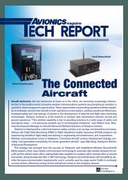
<strong>The</strong> Ethernet communication protocol<br />
is referred to as CSMA/CD (Carrier<br />
Sense, Multiple Access, and Collision<br />
Detection—see illustration below). Carrier<br />
sense means the hosts can detect whether<br />
the medium (coaxial cable) is idle or busy.<br />
Multiple access means that multiple hosts<br />
can be connected to the common medium.<br />
Collision detection means that, when a host<br />
transmits, it can detect whether its transmission<br />
has collided with the transmission of<br />
another host (or hosts).<br />
<strong>The</strong> original Ethernet<br />
data rate was 2.94 Mbs/s.<br />
<strong>The</strong> Ethernet local area<br />
network (LAN) is a halfduplex<br />
system in which<br />
collisions do occur.<br />
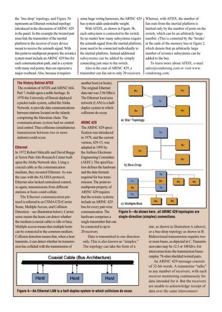
ARINC 429<br />
<strong>The</strong> ARINC 429 specification<br />
was introduced<br />
in 1978, and the current<br />
version, 429-15, was<br />
adopted in 1995 by<br />
the Airlines Electronic<br />
Engineering Committee<br />
(AEEC). <strong>The</strong> specification<br />
defines the hardware<br />
and the data <strong>for</strong>mats<br />
required <strong>for</strong> bus transmission.<br />
<strong>The</strong> point-tomultipoint<br />
property of<br />
ARINC 429 requires<br />
that the avionic systems<br />
include an ARINC 429<br />
bus <strong>for</strong> every pair-wise<br />
communication. <strong>The</strong><br />
hardware comprises a<br />
single transmitter that can<br />
be connected to up to<br />
20 receivers.<br />
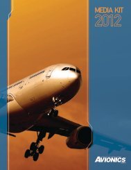
Data is transmitted in one direction<br />
only. This is also known as “simplex.”<br />
<strong>The</strong> topology can take the <strong>for</strong>m of a<br />
Figure 4—An Ethernet LAN is a half-duplex system in which collisions do occur.<br />
Figure 5—As shown here, all ARINC 429 topologies are<br />
single-direction (simplex) connections.<br />
star, as shown in illustration A (above),<br />
or a bus-drop topology as shown in B.<br />
Bidirectional transmission requires two<br />
or more buses, as depicted in C. Transmission<br />
rates may be 12.5 or 100 kb/s. For<br />
interconnections the transmission buses<br />
employ 78-ohm shielded twisted pairs.<br />
An ARINC 429 message consists<br />
of 32-bit words. A transmitter “talks”<br />
to any number of receivers, with each<br />
receiver monitoring continuously <strong>for</strong><br />
data intended <strong>for</strong> it. But the receivers<br />
are unable to acknowledge receipt of<br />
data over the same interconnect.