AFDX: The Next Generation Interconnect for ... - Aviation Today
AFDX: The Next Generation Interconnect for ... - Aviation Today
AFDX: The Next Generation Interconnect for ... - Aviation Today

You also want an ePaper? Increase the reach of your titles
YUMPU automatically turns print PDFs into web optimized ePapers that Google loves.
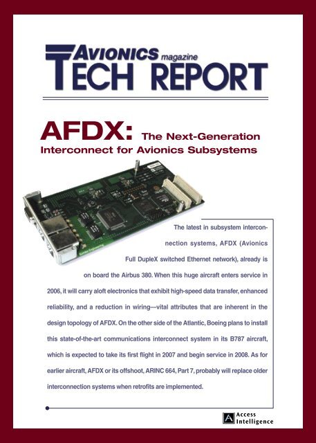
<strong>AFDX</strong>: <strong>The</strong> <strong>Next</strong>-<strong>Generation</strong><br />
<strong>Interconnect</strong> <strong>for</strong> Avionics Subsystems<br />
<strong>The</strong> latest in subsystem interconnection<br />
systems, <strong>AFDX</strong> (Avionics<br />
Full DupleX switched Ethernet network), already is<br />
on board the Airbus 380. When this huge aircraft enters service in<br />
2006, it will carry aloft electronics that exhibit high-speed data transfer, enhanced<br />
reliability, and a reduction in wiring—vital attributes that are inherent in the<br />
design topology of <strong>AFDX</strong>. On the other side of the Atlantic, Boeing plans to install<br />
this state-of-the-art communications interconnect system in its B787 aircraft,<br />
which is expected to take its first flight in 2007 and begin service in 2008. As <strong>for</strong><br />
earlier aircraft, <strong>AFDX</strong> or its offshoot, ARINC 664, Part 7, probably will replace older<br />
interconnection systems when retrofits are implemented.
<strong>AFDX</strong> is a standard that defines<br />
the electrical and protocol<br />
specifications (IEEE 802.3 and<br />
ARINC 664, Part 7) <strong>for</strong> the<br />
exchange of data between avionics<br />
subsystems. One thousand times faster<br />
than its predecessor ARINC 429, <strong>AFDX</strong><br />
builds upon the original concepts introduced<br />
by Airbus. <strong>The</strong> European aircraft<br />
manufacturer devised <strong>AFDX</strong> and named it,<br />
as part of the evolution of its A380 aircraft.<br />
As a result <strong>AFDX</strong>, and its offshoot, ARINC<br />
664, Part 7, have brought a number of highly<br />
significant improvements, both electrical<br />
and mechanical, to the interconnection of<br />
electronic subsystems aboard aircraft.<br />
Many electronic subsystems are on<br />
board large aircraft, such as inertial plat<strong>for</strong>ms,<br />
control systems, sensors systems,<br />
and communication systems. <strong>The</strong>y all<br />
demand high-reliability, high-speed<br />
in<strong>for</strong>mation transfer. Control systems and<br />
avionics, in particular, rely on complete<br />
and up-to-date data delivery from source<br />
to receiver in a timely fashion. For safetycritical<br />
systems, reliable real-time<br />
communications links are essential—and<br />
that is where <strong>AFDX</strong> has brought about<br />
major improvements. <strong>AFDX</strong> builds upon<br />
a number of earlier bus structures (see<br />
“<strong>The</strong> History Behind <strong>AFDX</strong>”, page 4).<br />
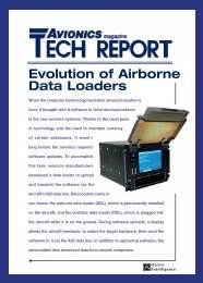
Figure 1— How subsystems interconnect with each other and the outside world.<br />
What is <strong>AFDX</strong>?<br />
As shown in Figure 1, an <strong>AFDX</strong> system<br />
comprises the following components:<br />
• Avionics Subsystems—the many<br />
traditional avionics subsystems on board an<br />
aircraft, such as the flight control computer,<br />
GPS and tire pressure-monitoring system.<br />
Together with an <strong>AFDX</strong> end system, an<br />
avionics computer provides a computing<br />
environment <strong>for</strong> hosting multiple avionics<br />
subsystems. Each avionics computer<br />
contains an embedded end system that connects<br />
the avionics subsystems to an <strong>AFDX</strong><br />
interconnect, as shown in the illustration.<br />
• <strong>AFDX</strong> End System–the system that<br />
provides the interface between avionics subsystems<br />
and an <strong>AFDX</strong> interconnect. <strong>The</strong> end<br />
systems guarantee a secure and reliable data<br />
interchange with other avionics subsystems.<br />
<strong>The</strong>y each export an application program<br />
interface (API) to the various subsystems,<br />
enabling them to communicate with each<br />
other via a simple message transfer interface.<br />
• <strong>AFDX</strong> <strong>Interconnect</strong>–which is a full<br />
duplex, switched Ethernet interface. It comprises<br />
a network of switches that <strong>for</strong>ward<br />
Ethernet frames to their appropriate destinations.<br />
Because it is based on Ethernet<br />
technology, <strong>AFDX</strong> is a departure from the<br />
traditional ARINC 429 point-to-point technology<br />
and Mil-Std-1553 bus technology.<br />
This interface is discussed below, in detail.<br />
Also shown in Figure 1, two of the end<br />
systems provide communications interfaces<br />
<strong>for</strong> three avionics subsystems, and the third<br />
end system supplies an interface <strong>for</strong> a gateway.<br />
<strong>The</strong> latter provides a communications<br />
path between the <strong>AFDX</strong> and external IP<br />
(Internet protocol) networks and typically<br />
is used <strong>for</strong> data loading and logging.<br />
<strong>The</strong> Problem with Ethernet<br />
Half-duplex switched mode Ethernet<br />
(see sidebar, page 4) is another name <strong>for</strong> the<br />
original Ethernet local area network (LAN).<br />
<strong>The</strong>re is an issue when multiple hosts are<br />
connected to the same communication<br />
medium, as is the case with the coaxial cable<br />
depicted in Figure 5 (page 4), where there<br />
is no central coordination. In this case two<br />
hosts could transmit simultaneously, causing<br />
their transmissions to collide. A need exists,<br />
there<strong>for</strong>e, <strong>for</strong> the hosts to be able to detect<br />
transmission collisions.<br />
A collision occurs when two or more<br />
hosts attempt to transmit at the same time.<br />
Each host, then, has to retransmit their<br />
data—which opens the possibility of another<br />
collision and the need to retransmit again.<br />
To avoid this phenomenon, each host must<br />
select a random transmission time from<br />
an interval <strong>for</strong> retransmitting the data. If a<br />
collision is again detected, the host selects<br />
another random time <strong>for</strong> transmission from<br />
an interval that is twice the size of the previous<br />
one, and so on. This is often referred to<br />
as the “binary exponential backoff strategy.”<br />
Since Ethernet has no central control,<br />
the packets of data could, theoretically,<br />
collide repeatedly, despite a binary exponential<br />
backoff strategy. <strong>The</strong>re is, in fact, a<br />
chance that an infinite chain of collisions<br />
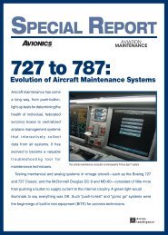
Figure 2—A full-duplex Ethernet switch<br />
that solves the collision problem.
could occur, and the packet would never<br />
be successfully transmitted. <strong>The</strong>re<strong>for</strong>e, in a<br />
half-duplex mode, very large transmission<br />
delays are possible due to collisions—a<br />
situation that would be unacceptable in an<br />
avionics data network.<br />
So, what is required—and what was<br />
implemented in <strong>AFDX</strong>—is an architecture<br />
in which the maximum amount of time <strong>for</strong><br />
one packet to reach its destination becomes<br />
known. Achieving this meant ridding the<br />
system of “contention.”<br />
are guaranteed that it will not be delayed<br />
<strong>for</strong> more than a given time interval, say no<br />
more than 400 microseconds.<br />
Instead of collisions and retransmissions,<br />
switching architecture can result in jitter<br />
due to the random delay introduced by one<br />
packet waiting <strong>for</strong> another to be transmitted.<br />
<strong>The</strong> extent of jitter introduced by an end<br />
system and switch must be controlled if<br />
deterministic behavior of the overall<br />
avionics system is to be achieved.<br />
Reducing Wire Runs<br />
In addition to the enhancements already<br />
described, <strong>AFDX</strong> delivers other benefits<br />
when compared to ARINC 429. Some of<br />
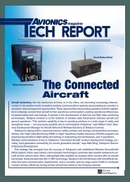
these distinctions are illustrated in Figure 3.<br />
In ARINC 429, as depicted in Figure 3a, is<br />
Eliminating Contention<br />
To do away with contention and hence the<br />
indeterminacy as to how long a packet takes<br />
to travel from sender to receiver, <strong>AFDX</strong><br />
adopted full-duplex switch Ethernet. It overcomes<br />
the issue of collisions inherent in<br />
half-duplex based Ethernet. As shown in<br />
Figure 2, each avionics subsystem—<br />
autopilot, heads-up display, etc.—connects<br />
directly to a switch over a full-duplex link<br />
that comprises two twisted pairs, one <strong>for</strong><br />
transmit (Tx) and one <strong>for</strong> receive (Rx). <strong>The</strong><br />
switch, which comprises all the components<br />
contained in the large box, is able to buffer<br />
packets <strong>for</strong> both reception and transmission.<br />
Figure 2 also shows that both the Rx and<br />
Tx buffers are capable of storing multiple<br />
incoming/outgoing packets in a FIFO (first<br />
in, first out) order. <strong>The</strong> role of the input/output<br />
(I/O) computer-processing unit (CPU)—<br />
moving packets from the incoming Rx buffers<br />
to the outgoing Tx buffers—is achieved<br />
by examining each arriving packet that is<br />
next in line in the Rx buffer to determine its<br />
destination address (virtual link identifier).<br />
<strong>The</strong> CPU then checks with the <strong>for</strong>warding<br />
table to determine which Tx buffer(s) are<br />
to receive the packet. <strong>The</strong> packet is subsequently<br />
copied into the Tx buffer(s), via the<br />
memory bus and transmitted again in FIFO<br />
order to the selected avionics subsystem or to<br />
another switch. This type of switching architecture<br />
is referred to as “store and <strong>for</strong>ward.”<br />
Consequently, the full-duplex switch<br />
architecture eliminates contention, which<br />
causes collisions. (In practice, <strong>AFDX</strong><br />
mandates that two redundant switch<br />
architectures are employed.)<br />
<strong>The</strong>oretically, an Rx or Tx buffer could<br />
overflow. But this will not happen if the buffer<br />
requirements were planned correctly in<br />
the original design and made large enough.<br />
With <strong>AFDX</strong> you may not be able to get<br />
your message out immediately, but you<br />
Figure 3—Unlike ARINC 429 (a) with <strong>AFDX</strong> (b) each subsystem requires only a single<br />
connection to the switch, which can have an arbitrarily large number of ports.<br />
Condor Engineering and <strong>AFDX</strong><br />
Condor Engineering has been engaged<br />
in the support of avionics protocols <strong>for</strong><br />
more than 16 years. In keeping with that<br />
tradition, Condor has recently introduced<br />
an innovative and technically advanced<br />
PMC (PCI mezzanine card) <strong>for</strong> <strong>AFDX</strong><br />
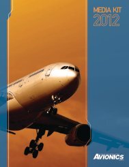
protocol (figure 4). <strong>The</strong> Dual-Port<br />
ARINC 664 Card supports full throughput,<br />
simultaneously, on all channels. Its<br />
two independent, full-bandwidth ports<br />
can be employed <strong>for</strong> traffic monitoring,<br />
traffic generation, external triggering,<br />
and analysis. <strong>The</strong> card also offers highresolution,<br />
time-tagging of incoming<br />
Ethernet packets, as well as highly<br />
accurate traffic generation. An IRIG-B<br />
(Inter-Range Instrumentation Group,<br />
Standard B) receiver/generator is included<br />
<strong>for</strong> synchronization to an external IRIG-<br />
B time source and <strong>for</strong> synchronization<br />
between multiple network interface cards.<br />
Advanced <strong>AFDX</strong> traffic generation<br />
and end system libraries are included.<br />
<strong>The</strong> end system library implements the<br />
complete <strong>AFDX</strong> protocol stack and uses<br />
an XML (extensible markup language)-<br />
based configuration file approach <strong>for</strong><br />
specifying an <strong>AFDX</strong> network.<br />
For further details regarding the<br />
<strong>AFDX</strong> protocol, refer to Condor Engineering’s<br />
<strong>AFDX</strong> Protocol Tutorial at www.<br />
condoreng.com/support/downloads/tutorials/index.shtml.
the ‘bus drop’ topology, and Figure 3b<br />
represents an Ethernet switched topology<br />
introduced in the discussion of ARINC 429<br />
in the panel. In this example the twisted pair<br />
must link the transmitter of the inertial<br />
plat<strong>for</strong>m to the receiver of every device<br />
meant to receive the azimuth signal. With<br />
this point-to-multipoint property the avionics<br />
system must include an ARINC 429 bus <strong>for</strong><br />
each communication path, and in a system<br />
with many end points, that can represent a<br />
major overhead. Also, because it requires<br />
some huge wiring harnesses, the ARINC 429<br />
bus system adds undesirable weight.<br />
With <strong>AFDX</strong>, as shown in Figure 3b,<br />
each subsystem is connected to the switch.<br />
So no matter how many subsystems require<br />
the azimuth signal from the inertial plat<strong>for</strong>m,<br />
none need to be connected individually to<br />
the inertial plat<strong>for</strong>m. Instead additional<br />
subsystems can be added by simply<br />
connecting just once to the switch.<br />
Also in the case of ARINC 429, a<br />
transmitter can fan out to only 20 receivers.<br />
Whereas, with <strong>AFDX</strong>, the number of<br />
fan-outs from the inertial plat<strong>for</strong>m is<br />
limited only by the number of ports on the<br />
switch, which can be an arbitrarily large<br />
number. (This is connoted by the ‘breaks’<br />
at the ends of the memory bus in figure 2,<br />
which denote that an arbitrarily large<br />
number of avionics subsystems can be<br />
added to the bus.<br />
To learn more about <strong>AFDX</strong>, e-mail<br />
sales@condoreng.com or visit www.<br />
condoreng.com.<br />
<strong>The</strong> History Behind <strong>AFDX</strong><br />
<strong>The</strong> evolution of <strong>AFDX</strong> and ARINC 664,<br />
Part 7, builds upon a noble heritage. In<br />
1970 the University of Hawaii deployed<br />
a packet radio system, called the Aloha<br />
Network, to provide data communications<br />
between stations located on the islands<br />
comprising the Hawaiian chain. <strong>The</strong><br />
communications system had no centralized<br />
control. Thus collisions (simultaneous<br />
transmission between two or more<br />
stations) could occur.<br />
Ethernet<br />
In 1972 Robert Metcalfe and David Boggs<br />
at Xerox Palo Alto Research Center built<br />
upon the Aloha Network idea. Using a<br />
coaxial cable as the communication<br />
medium, they invented Ethernet. As was<br />
the case with the ALOHA protocol,<br />
Ethernet also lacked centralized control,<br />
so again, transmissions from different<br />
stations or hosts could collide.<br />
<strong>The</strong> Ethernet communication protocol<br />
is referred to as CSMA/CD (Carrier<br />
Sense, Multiple Access, and Collision<br />
Detection—see illustration below). Carrier<br />
sense means the hosts can detect whether<br />
the medium (coaxial cable) is idle or busy.<br />
Multiple access means that multiple hosts<br />
can be connected to the common medium.<br />
Collision detection means that, when a host<br />
transmits, it can detect whether its transmission<br />
has collided with the transmission of<br />
another host (or hosts).<br />
<strong>The</strong> original Ethernet<br />
data rate was 2.94 Mbs/s.<br />
<strong>The</strong> Ethernet local area<br />
network (LAN) is a halfduplex<br />
system in which<br />
collisions do occur.<br />
ARINC 429<br />
<strong>The</strong> ARINC 429 specification<br />
was introduced<br />
in 1978, and the current<br />
version, 429-15, was<br />
adopted in 1995 by<br />
the Airlines Electronic<br />
Engineering Committee<br />
(AEEC). <strong>The</strong> specification<br />
defines the hardware<br />
and the data <strong>for</strong>mats<br />
required <strong>for</strong> bus transmission.<br />
<strong>The</strong> point-tomultipoint<br />
property of<br />
ARINC 429 requires<br />
that the avionic systems<br />
include an ARINC 429<br />
bus <strong>for</strong> every pair-wise<br />
communication. <strong>The</strong><br />
hardware comprises a<br />
single transmitter that can<br />
be connected to up to<br />
20 receivers.<br />
Data is transmitted in one direction<br />
only. This is also known as “simplex.”<br />
<strong>The</strong> topology can take the <strong>for</strong>m of a<br />
Figure 4—An Ethernet LAN is a half-duplex system in which collisions do occur.<br />
Figure 5—As shown here, all ARINC 429 topologies are<br />
single-direction (simplex) connections.<br />
star, as shown in illustration A (above),<br />
or a bus-drop topology as shown in B.<br />
Bidirectional transmission requires two<br />
or more buses, as depicted in C. Transmission<br />
rates may be 12.5 or 100 kb/s. For<br />
interconnections the transmission buses<br />
employ 78-ohm shielded twisted pairs.<br />
An ARINC 429 message consists<br />
of 32-bit words. A transmitter “talks”<br />
to any number of receivers, with each<br />
receiver monitoring continuously <strong>for</strong><br />
data intended <strong>for</strong> it. But the receivers<br />
are unable to acknowledge receipt of<br />
data over the same interconnect.