
You also want an ePaper? Increase the reach of your titles
YUMPU automatically turns print PDFs into web optimized ePapers that Google loves.
<strong>Netopia</strong> <strong>R7100</strong> <strong>Application</strong> <strong>Note</strong><br />
Part Number 6190003-00-01<br />
Copper Edge 200 and Cisco Configuration Using RFC1483 via V.35<br />
Written by: Ryan Eccles<br />
Date: 12/17/99<br />
Revised: None<br />
This application note describes how to configure a <strong>Netopia</strong> <strong>R7100</strong><br />
router to connect to a Copper Mountain CE200 DSLAM and<br />
Cisco router using RFC 1483 bridged encapsulation.<br />
Introduction<br />
The <strong>Netopia</strong> <strong>R7100</strong> is a Copper Mountain CE 200-compatible multi-protocol SDSL router capable of using<br />
several types of data link protocols, including PPP, RFC1483, and Frame Relay. The purpose of this<br />
document is to outline the procedures for configuring a <strong>Netopia</strong> <strong>R7100</strong> router, Copper Mountain CE200<br />
DSLAM, and Cisco 4500M router on an SDSL link using RFC1483 bridged as the data link encapsulation.<br />
This application note is specific to applications where a V.35 interface is used between the Cisco 4500M<br />
and the CE200.<br />
<strong>Note</strong>: This application note is meant to be used for reference purposes only, and will most likely have to be<br />
modified to suit individual user’s needs. A general working knowledge of the equipment described below is<br />
assumed for this application note. For more specific information about the <strong>Netopia</strong> <strong>R7100</strong>, please see the<br />
<strong>Netopia</strong> <strong>R7100</strong> Reference Manual available on the <strong>Netopia</strong> CustomerCare CD or online at<br />
http://www.netopia.com/support.<br />
Network Diagram<br />
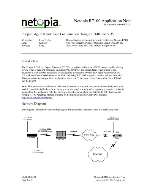
This diagram illustrates the network topology and IP addressing schemes used in this application note:<br />
192.168.1.1<br />
255.255.255.0<br />
172.16.1.1<br />
255.255.255.252<br />
<strong>Netopia</strong><br />
784Kbps SDSL<br />
RFC 1483 Bridged DLCI 239 DLCI 239<br />
CE 200<br />
Frame Relay<br />
ISP<br />
Cisco<br />
172.16.1.2<br />
255.255.255.252<br />
Internet<br />
6190003-00-01 <strong>Netopia</strong> <strong>R7100</strong> <strong>Application</strong> <strong>Note</strong><br />
Page 1 of 9<br />
Copyright © 1999 <strong>Netopia</strong> Inc.
Prerequisites<br />
This application note assumes you are using the following equipment and configurations:<br />
Hardware<br />
<strong>Netopia</strong> <strong>R7100</strong> Router<br />
Cisco Router<br />
Copper Mountain CE200<br />
<strong>Note</strong>s<br />
Must be running firmware version 4.3.8 or above.<br />
Must be running IOS software release 11.2 or above and have<br />
a Frame Relay connection to the CE200.<br />
Must have an SDSL line card installed and be running<br />
firmware version 2.0 or above.<br />
Configuration<br />
Configuration of the <strong>R7100</strong><br />
WAN Setup<br />
This section describes how to set up the SDSL interface on the <strong>Netopia</strong> <strong>R7100</strong> router to use RFC 1483<br />
Bridged Encapsulation.<br />
1. From the Main Menu of the <strong>Netopia</strong> user interface, select Easy Setup and press Enter. You will be<br />
presented with the SDSL Line Configuration screen.<br />
An example of the SDSL Line Configuration screen is shown in Figure 1 below:<br />
SDSL Line Configuration<br />
Data Link Encapsulation...<br />
RFC1483<br />
TO MAIN MENU<br />
NEXT SCREEN<br />
Return/Enter goes to new screen.<br />
Enter Information supplied to you by your telephone company.<br />
Figure 1: <strong>Netopia</strong> SDSL Line Configuration screen<br />
The default Data Link Encapsulation Value is RFC1483 and should not be changed.<br />
6190003-00-01 <strong>Netopia</strong> <strong>R7100</strong> <strong>Application</strong> <strong>Note</strong><br />
Page 2 of 9<br />
Copyright © 1999 <strong>Netopia</strong> Inc.
2. Select Next Screen at the bottom of the menu and press Enter. You will be presented with the<br />
Connection Profile 1 screen.<br />
An example of the Connection Profile 1 screen is shown in Figure 2 below:<br />
Connection Profile 1: Easy Setup Profile<br />
Connection Profile Name:<br />
Easy Setup Profile<br />
Address Translation Enabled:<br />
IP Addressing...<br />
Yes<br />
Numbered<br />
Local WAN IP Address: 172.16.1.2<br />
Local WAN IP Mask: 255.255.255.252<br />
PREVIOUS SCREEN<br />
NEXT SCREEN<br />
Return accepts * ESC cancels * Left/Right moves insertion point * Del deletes.<br />
Enter basic information about your WAN connection with this screen.<br />
Figure 2: Connection Profile 1 screen<br />
3. Based on the IP addressing scheme in the network diagram on Page 1, the values of the Connection<br />
Profile 1 menu items should be as follows:<br />
Connection Profile Name: Easy Setup Profile The default value is correct. It can be changed to<br />
any name.<br />
Address Translation Enabled: Yes Since we are using private, non-routable IP<br />
addresses on the LAN, the value would be Yes.<br />
IP Addressing: Numbered Since there is an IP address on the WAN side of<br />
the <strong>Netopia</strong> Router, the value would be Numbered.<br />
Local WAN IP Address: 172.16.1.2 Based on the network diagram on Page 1.<br />
Local WAN IP Mask: 255.255.255.252 Based on the network diagram on Page 1.<br />
4. Select Next Screen at the bottom of the menu screen and press Enter. You will be presented with the<br />
IP Easy Setup screen.<br />
6190003-00-01 <strong>Netopia</strong> <strong>R7100</strong> <strong>Application</strong> <strong>Note</strong><br />
Page 3 of 9<br />
Copyright © 1999 <strong>Netopia</strong> Inc.
An example of the IP Easy Setup screen is shown below in Figure 3:<br />
IP Easy Setup<br />
Ethernet IP Address: 192.168.1.1<br />
Ethernet Subnet Mask: 255.255.255.0<br />
Domain Name:<br />
Primary Domain Name Server: 0.0.0.0<br />
Secondary Domain Name Server: 0.0.0.0<br />
Default IP Gateway: 172.16.1.1<br />
IP Address Serving:<br />
On<br />
Number of Client IP Addresses: 100<br />
1st Client Address: 192.168.1.100<br />
PREVIOUS SCREEN<br />
NEXT SCREEN<br />
Enter an IP address in decimal and dot form (xxx.xxx.xxx.xxx).<br />
Set up the basic IP & IPX attributes of your <strong>Netopia</strong> in this screen.<br />
Figure 3: IP Easy Setup screen<br />
5. Based on the IP addressing scheme in the network diagram on Page 1, the values of the IP Easy Setup<br />
menu items should be as follows:<br />
Ethernet IP Address: 192.168.1.1 Based on the network diagram on Page 1. This is<br />
also the default value.<br />
Ethernet Subnet Mask: 255.255.255.0 Based on the network diagram on Page 1. This is<br />
also the default value.<br />
Domain Name:<br />
<br />
Primary Domain Name Server: <br />
Secondary Domain Name <br />
Server:<br />
Default IP Gateway: 172.16.1.1 The Default IP Gateway of the <strong>Netopia</strong> Router will<br />
be the IP address of the Cisco router.<br />
IP Address Serving: Off The default value is On. When On, the <strong>Netopia</strong><br />
Router will serve out 100 IP addresses on the LAN<br />
via DHCP.<br />
6. Select Next Screen at the bottom of the menu and press Enter. You will be presented with the Easy<br />
Setup Security Configuration screen.<br />
6190003-00-01 <strong>Netopia</strong> <strong>R7100</strong> <strong>Application</strong> <strong>Note</strong><br />
Page 4 of 9<br />
Copyright © 1999 <strong>Netopia</strong> Inc.
An example of the Easy Setup Security Configuration screen is shown below in Figure 4:<br />
Easy Setup Security Configuration<br />
It is strongly suggested that you password-protect configuration access to your<br />
<strong>Netopia</strong>. By entering a Name and Password pair here, access via serial,<br />
Telnet and Web Server will be password-protected.<br />
Be sure to remember what you have typed here, because you will be prompted for<br />
it each time you configure this <strong>Netopia</strong>.<br />
You can remove an existing Name and Password by clearing both fields below.<br />
Write Access Name:<br />
Write Access Password:<br />
PREVIOUS SCREEN TO MAIN MENU RESTART DEVICE<br />
Configure a Configuration Access Name and Password here.<br />
Figure 4: Easy Setup Security Configuration screen<br />
7. If you choose to set a Write Access name and password, you can do so here. For this example, we will<br />
not. Select Restart Device at the bottom of the screen and press Enter. You will be presented with a<br />
choice to cancel or continue restarting the device. Select Continue and press Enter. The <strong>Netopia</strong><br />
Router will restart and no additional configuration should be necessary.<br />
Copper Edge 200 DSLAM Configuration<br />
For this example, we will use Port 1.7.4 on the SDSL line card in Slot 1.7 of the DSLAM. The V.35<br />
Connection between the DSLAM and Cisco router will come off of Port 1.3 on the DSLAM and use Frame<br />
Relay DLCI 239. We will also be using the Copper Craft command line tool for configuration functions.<br />
1. Log in to the DSLAM Copper Craft command line.<br />
2. Issue the following command which sets the proper network model, encapsulation type, and<br />
destination permanent instance identifier for the CPE port:<br />
set cmif [1.7.4] netmodel=vwan encapsulation=rfc1483 destpii=1.3.1.239<br />
The DSLAM has various network models which depend on the type of CPE connection being made.<br />
The value for this example is VWAN. The encapsulation type for the connection between the DSLAM<br />
and <strong>Netopia</strong> is rfc1483 bridged. The destination permanent instance identifier is the connection to the<br />
ISP that will be mapped to the port that the <strong>Netopia</strong> Router is connected to.<br />
3. Press Enter. The words “Set Successful” should be displayed on the screen. If you do not see these<br />
words or receive an error message, please refer to the Copper Mountain CE200 user guide.<br />
6190003-00-01 <strong>Netopia</strong> <strong>R7100</strong> <strong>Application</strong> <strong>Note</strong><br />
Page 5 of 9<br />
Copyright © 1999 <strong>Netopia</strong> Inc.
4. Set the DSLAM-to-Cisco frame relay PVC active by issuing the following command:<br />
set frpvc [1.3.1.239] state=active<br />
5. The default data rate on a Copper Mountain CE200 SDSL port is 784 Kbps. For this example, we will<br />
not change that value. If you wish to change the value to 1568 Kbps, for instance, you would issue the<br />
following command:<br />
set cmhdslmodem [1.7.4] datarate=1568<br />
<strong>Note</strong>: The <strong>Netopia</strong> Router does not need to be configured with a data rate value. The rate will be<br />
negotiated between the DSLAM and the <strong>Netopia</strong> Router automatically.<br />
6. Issue the following command to verify that the configuration changes have taken effect:<br />
get cmif [1.7.4]<br />
The output of this command should look similar to the following:<br />
Group: cmIfaceTable<br />
Instance: [1.7.4.0]<br />
PII = 1.7.4.0<br />
IfIndex = 1.7.4.0<br />
Name<br />
= <strong>Netopia</strong> Test Port<br />
GroupName = ""<br />
AdditionalInfo = ""<br />
NetModel<br />
= VWAN<br />
IpAddr = 0.0.0.0<br />
NetMask = 0.0.0.0<br />
MacAddr<br />
= ff.ff.ff.ff.ff.ff<br />
BurnedInMacAddr = 0.0.0.0.0.0<br />
FarEndAddr = 0.0.0.0<br />
DestPII = 1.3.1.239<br />
CMCPCompatible = Yes<br />
EncapsulationType = rfc1483<br />
FwdMode<br />
= VWAN-point-to-point or VWAN-bridge<br />
Pix = 30<br />
ServiceClass<br />
= D<br />
7. Issue the same command for the DSLAM-to-Cisco port:<br />
get cmif [1.3.1.239]<br />
The output of this command should look similar to the following:<br />
Group: cmIfaceTable<br />
Instance: [1.3.1.239]<br />
PII = 1.3.1.239<br />
IfIndex = 1.3.1.239<br />
Name = ""<br />
GroupName = ""<br />
AdditionalInfo = ""<br />
NetModel<br />
= VWAN<br />
IpAddr = 0.0.0.0<br />
NetMask = 0.0.0.0<br />
6190003-00-01 <strong>Netopia</strong> <strong>R7100</strong> <strong>Application</strong> <strong>Note</strong><br />
Page 6 of 9<br />
Copyright © 1999 <strong>Netopia</strong> Inc.
MacAddr<br />
= ff.ff.ff.ff.ff.ff<br />
BurnedInMacAddr = ff.ff.ff.ff.ff.ff<br />
FarEndAddr = 0.0.0.0<br />
DestPII = 1.7.4.0<br />
CMCPCompatible = No<br />
EncapsulationType = rfc1490<br />
FwdMode<br />
= VWAN-point-to-point<br />
Pix = 541<br />
ServiceClass<br />
= None<br />
8. At this point, the SDSL line is ready to be plugged into WAN port 1 on the <strong>Netopia</strong> Router. Once the<br />
<strong>Netopia</strong> Router has been connected to the SDSL line, verify the CPE port interface configuration again<br />
on the CE200 by issuing the following command:<br />
get cmif [1.7.4]<br />
The output of this command should look similar to the following:<br />
Group: cmIfaceTable<br />
Instance: [1.7.4.0]<br />
PII = 1.7.4.0<br />
IfIndex = 1.7.4.0<br />
Name<br />
= <strong>Netopia</strong> Test Port<br />
GroupName = ""<br />
AdditionalInfo = ""<br />
NetModel<br />
= VWAN<br />
IpAddr = 0.0.0.0<br />
NetMask = 0.0.0.0<br />
MacAddr<br />
= ff.ff.ff.ff.ff.ff<br />
BurnedInMacAddr = 0.0.c5.70.d4.62<br />
FarEndAddr = 0.0.0.0<br />
DestPII = 1.3.1.239<br />
CMCPCompatible = Yes<br />
EncapsulationType = rfc1483<br />
FwdMode<br />
= VWAN-point-to-point<br />
Pix = 30<br />
ServiceClass<br />
= D<br />
Verifying The Connection<br />
The configuration of the CE 200 and <strong>Netopia</strong> <strong>R7100</strong> routers are now complete. Be sure the <strong>Netopia</strong> <strong>R7100</strong><br />
router is trained with the CE200, as indicated by the Ready and Channel 1 LEDs being solid green.<br />
Cisco 4500M Configuration<br />
1. Log into the Cisco IOS command line and enter configuration mode.<br />
2. Since RFC1483 is a bridged protocol by nature, the Cisco must have a Bridged Virtual Interface (BVI).<br />
The Cisco must also be capable of performing Integrated Router/Bridge (IRB) functions which enable<br />
routing between bridged and routed interfaces. Issue the following commands to create a BVI:<br />
cisco#conf t<br />
# Enter Config. Mode.<br />
Enter configuration commands, one per line. End with CNTL/Z.<br />
cisco(config)#bridge irb # Enable IRB functions.<br />
cisco(config)#int bvi 1 # Create BVI 1.<br />
Bridge group 223 is not configured<br />
% No interface specified for interface_command<br />
6190003-00-01 <strong>Netopia</strong> <strong>R7100</strong> <strong>Application</strong> <strong>Note</strong><br />
Page 7 of 9<br />
Copyright © 1999 <strong>Netopia</strong> Inc.
cisco(config)#bridge 1 protocol ieee<br />
cisco(config)#bridge 1 route ip<br />
# Set the protocol type.<br />
# Enable the BVI to accept<br />
# and route routable IP<br />
# packets received from<br />
# the bridge group.<br />
3. We must now assign an IP address to the BVI by using the following commands:<br />
cisco(config)#int bvi 1<br />
cisco(config-if)#ip address 172.16.1.1 255.255.255.0<br />
cisco(config-if)#exit<br />
# Exit to global configuration mode<br />
4. The Cisco now needs a Frame Relay interface on which to speak with the DSLAM. For this example,<br />
the Cisco will be using Synchronous Serial interface number 1. Enter configuration mode and create a<br />
frame relay interface with DLCI value 239 by using the following commands:<br />
cisco(config)#int s1.239 point-to-point<br />
cisco(config-subif)#frame-relay interface-dlci 239<br />
cisco(config-fr-dlci)#exit<br />
5. The final step is to associate this sub-interface with the BVI that you created in step 2. The command<br />
to do this is as follows:<br />
cisco(config-subif)#bridge-group 1<br />
6. Exit configuration mode and save the changes by using the following commands:<br />
cisco(config-subif)#end<br />
cisco#write<br />
Building configuration...<br />
cisco#<br />
7. The Cisco configuration should now look similar to the following:<br />
interface Serial1<br />
no ip address<br />
no ip directed-broadcast<br />
encapsulation frame-relay IETF<br />
no ip route-cache<br />
no ip mroute-cache<br />
clockrate 2000000<br />
frame-relay lmi-type ansi<br />
frame-relay intf-type dce<br />
!<br />
interface Serial1.239 point-to-point<br />
no ip directed-broadcast<br />
no ip route-cache<br />
no ip mroute-cache<br />
frame-relay interface-dlci 239<br />
bridge-group 1<br />
!<br />
interface BVI1<br />
ip address 172.16.1.1 255.255.255.0<br />
no ip directed-broadcast<br />
!<br />
6190003-00-01 <strong>Netopia</strong> <strong>R7100</strong> <strong>Application</strong> <strong>Note</strong><br />
Page 8 of 9<br />
Copyright © 1999 <strong>Netopia</strong> Inc.
idge 1 protocol ieee<br />
bridge 1 route ip<br />
!<br />
end<br />
Testing the Connection<br />
At this point, there should be full IP connectivity between the <strong>Netopia</strong> <strong>R7100</strong> router and the Cisco router.<br />
To test this connection, access the command line of the Cisco router and ping the <strong>Netopia</strong> Router’s WAN<br />
IP address. The results should be as follows:<br />
cisco#ping 172.16.1.2<br />
Type escape sequence to abort.<br />
Sending 5, 100-byte ICMP Echos to 172.16.1.2, timeout is 2 seconds:<br />
!!!!!<br />
Success rate is 100 percent (5/5), round-trip min/avg/max = 8/18/60 ms<br />
A successful connection is indicated by PING replies. If the PING test fails, or if the SDSL line does not<br />
train, consult the CE200, Cisco router, and <strong>Netopia</strong> <strong>R7100</strong> router’s reference guides for troubleshooting<br />
information.<br />
6190003-00-01 <strong>Netopia</strong> <strong>R7100</strong> <strong>Application</strong> <strong>Note</strong><br />
Page 9 of 9<br />
Copyright © 1999 <strong>Netopia</strong> Inc.