Performance curves - MGS
Performance curves - MGS
Performance curves - MGS

You also want an ePaper? Increase the reach of your titles
YUMPU automatically turns print PDFs into web optimized ePapers that Google loves.
DATASHEET<br />
Grundfos SP Range<br />
Applications<br />
~ Geothermal Open Loops<br />
~<br />
~<br />
~<br />
Wide product range<br />
High efficiency<br />
Stainless steel construction<br />
~ Lightweight<br />
Low installation costs<br />
~<br />
~<br />
~<br />
Features<br />
Rewindable motors<br />
Over temperature protection<br />
Grundfos SP Range offers energy-efficient submersible pumps<br />
ranging from 1 to 280m3/h. The range consists of many pump sizes<br />
and each pump size is available with an optional number of stages to<br />
match any duty point.<br />
Sand Resistant Materials and Design<br />
Most submersible pumps can run indefinitely in clean cold water. In<br />
real life however, groundwater often contains abrasives such as sand<br />
which sooner or later will wear out both pump and motor. In order to<br />
minimise wear and to provide maximum life and optimum<br />
performance, the SP range is designed to allow the suspended<br />
particles to be flushed out of the pump with the pumped liquid. Both<br />
the chambers and the impellers of the SP range are made of high<br />
grade stainless steel. As standard, all Grundfos SP models are made<br />
entirely of stainless steel DIN W.-Nr.1.4301 (AISI 304).<br />
High Motor Efficiency<br />
When focussing on efficiency, remember that the motor is just as<br />
important as the pump. Hydraulic efficiency will not do it alone. This is<br />
why there is a complete range of highly efficient submersible motors<br />
which match the advanced hydraulics of the SP range.<br />
Attention should also be attached to the submersible pump cable. Too<br />
small a cable reduces motor efficiency and may cause overheating of<br />
the motor and a maximum 1% cable loss is recommended.<br />
Motor Burn Protection<br />
Almost all motor failures which occur in submersible pumps are<br />
caused by too high motor pressure. The Grundfos SP range offers a<br />
failure rate of close to zero.<br />
Accessories<br />
A wide range of accessories including pump cable, flanges, starters,<br />
avalves are available to suit all applications.<br />
Specifications & products subject to change without prior notice<br />
A division of<br />
Marton Geotechnical Services Ltd<br />
www.geothermalsupplies.co.uk e info@geothermalsupplies.co.uk t +44(0)2476 328900 f +44(0)2476 328901<br />
Heyford Close, Alderman’s Green Industrial Estate, Coventry, West Midlands CV2 2QB England<br />
V1.0 08/2011
Contents<br />
General data<br />
<strong>Performance</strong> range 3<br />
Applications 4<br />
Type key 4<br />
Pumped liquids 4<br />
Curve conditions 4<br />
Pump range 5<br />
Motor range 5<br />
Motor protection and controllers 5<br />
Submersible pumps<br />
Features and benefits 6<br />
Material specification 8<br />
Submersible motors<br />
Features and benefits 9<br />
Shaft seal 11<br />
MS 402 11<br />
MS 4000, MS6 11<br />
Material specification for MS motors 12<br />
Material specification for MMS 6000 to 12000 motors 14<br />
<strong>Performance</strong> <strong>curves</strong>/<br />
Technical data<br />
SP 1A 16<br />
SP 2A 18<br />
SP 3A 20<br />
SP 5A 22<br />
SP 8A 24<br />
SP 14A 26<br />
SP 17 28<br />
SP 30 33<br />
SP 46 38<br />
SP 60 43<br />
SP 77 48<br />
SP 95 53<br />
SP 125 58<br />
SP 160 63<br />
SP 215 68<br />
Accessories<br />
CUE frequency converter 79<br />
MP 204 motor protector 82<br />
G100 gateway 85<br />
Connecting pieces 87<br />
Cable termination kit with plug 88<br />
Cable termination kit, type KM 88<br />
Mastik for flat cables 89<br />
Cable termination kit, types M0 to M6 89<br />
Submersible drop cable 90<br />
Zinc anodes 90<br />
Flow sleeves 91<br />
SA-SPM control boxes 91<br />
Capacitors for MS 402B PSC 91<br />
Pt100 sensor 92<br />
Pt1000 sensor 94<br />
Energy consumption<br />
Energy consumption of submersible pumps 96<br />
Cable sizing<br />
Cables 97<br />
Voltage drop: 1 % 98<br />
Voltage drop: 3 % 99<br />
Table of head losses<br />
Head losses in ordinary water pipes 101<br />
Head losses in plastic pipes 102<br />
Further product documentation<br />
WebCAPS 103<br />
WinCAPS 104<br />
Electrical data<br />
1 x 230 V, submersible motors 73<br />
3 x 230 V, submersible motors 73<br />
3 x 230 V, submersible rewindable motors 74<br />
3 x 400 V, submersible motors 74<br />
3 x 400 V, submersible industrial motors 75<br />
3 x 400 V, submersible motors 75<br />
3 x 400 V, submersible rewindable motors 76<br />
3 x 500 V, submersible motors 77<br />
3 x 500 V, submersible industrial motors 77<br />
3 x 500 V, submersible rewindable motors 78<br />
2
General data<br />
SP A, SP<br />
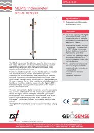
<strong>Performance</strong> range<br />
p<br />
[kPa]<br />
6000<br />
H<br />
[m]<br />
600<br />
SP<br />
50 Hz<br />
4000<br />
400<br />
2000<br />
200<br />
1000<br />
100<br />
800<br />
80<br />
600<br />
60<br />
400<br />
40<br />
SP 1A<br />
SP 2A<br />
SP 3A<br />
SP 5A<br />
SP 8A<br />
SP 14A<br />
SP 17<br />
SP 30<br />
SP 46<br />
SP 60<br />
SP 77<br />
SP 95<br />
SP 125<br />
SP160<br />
SP 215<br />
200<br />
20<br />
100<br />
10<br />
1 2 4 6 8 10 20 40 60 80 100 200 400<br />
Q [m³/h]<br />
0.4 0.6 0.8 1 2 4 6 8 10 20 40 60 Q [l/s]<br />
TM00 7254 4702<br />
3
General data<br />
SP A, SP<br />
Applications<br />
The SP A and SP pumps are suitable for the following<br />
applications:<br />
• raw-water supply<br />
• irrigation systems<br />
• groundwater lowering<br />
• pressure boosting<br />
• fountain applications<br />
• mining applications<br />
• off-shore applications.<br />
Type key<br />
Example SP 95 - 5 - A B N<br />
Type range (SP A, SP)<br />
Rated flow rate in m 3 /h<br />
Number of impellers<br />
First reduced-diameter impeller (A, B or C)<br />
Second reduced-diameter impeller (A, B or C)<br />
Stainless-steel parts of material<br />
= EN 1.4301<br />
N = EN 1.4401<br />
R = EN 1.4539<br />
Pumped liquids<br />
Clean, thin, non-aggressive liquids without solid<br />
particles or fibres.<br />
The special SP A-N and SP-N versions made of<br />
stainless steel to EN 1.4401 and SP A-R and SP-R<br />
versions made of stainless steel to EN 1.4539 are<br />
available for applications involving aggressive liquids.<br />
Maximum liquid temperature<br />
Grundfos motor<br />
Flow velocity<br />
past motor<br />
[m/s]<br />
Installation<br />
Vertical<br />
[°C]<br />
Horizontal<br />
[°C]<br />
MS 4" 0.15 40 40<br />
MS6 T30 versions 0.15 30 30<br />
MS 4" industrial versions 0.15 60 60<br />
MS6 T60 versions 1.0 60 60<br />
MMS6 with PVC in the<br />
0.15 25 25<br />
windings<br />
0.50 30 30<br />
MMS6 with PE/PA in the<br />
0.15 45 45<br />
windings<br />
0.50 50 50<br />
MMS 6000, 8000, 10000,<br />
0.15 25 25<br />
12000 rewindable with PVC<br />
in the windings<br />
0.50 30 30<br />
MMS 6000, 8000, 10000,<br />
0.15 40 40<br />
12000 rewindable with PE/<br />
PA in the windings<br />
0.50 45 45<br />
Note: For MMS 6000, 37 kW, MMS 8000, 110 kW, and MMS 10000,<br />
170 kW, the maximum liquid temperature is 5 °C lower than the values<br />
stated in the table above. For MMS 10000, 190 kW, the temperature is<br />
10 °C lower.<br />
Operating pressure<br />
Grundfos motor<br />
MS 402<br />
MS 4000 and 6"<br />
MMS6, MMS 6000, 8000, 10000,<br />
12000 rewindable<br />
Curve conditions<br />
Maximum operating pressure<br />
1.5 MPa (15 bar)<br />
6 MPa (60 bar)<br />
The conditions below apply to the <strong>curves</strong> on pages<br />
16 to 72:<br />
General conditions<br />
• Curve tolerances according to ISO 9906, Annex A.<br />
• The performance <strong>curves</strong> show pump performance<br />
at actual speed, cf. standard motor range.<br />
The speeds of the motors are approximately<br />
4" motors: n = 2870 min -1<br />
6" motors: n = 2870 min -1<br />
8" to 12" motors: n = 2900 min -1 .<br />
• The measurements were made with airless water at<br />
a temperature of 20 °C. The <strong>curves</strong> apply to a<br />
kinematic viscosity of 1 mm 2 /s (1 cSt). When<br />
pumping liquids with a density higher than that of<br />
water, use motors with correspondingly higher<br />
outputs.<br />
• The bold <strong>curves</strong> indicate the recommended<br />
performance range.<br />
• The performance <strong>curves</strong> are inclusive of possible<br />
losses such as non-return valve loss.<br />
SP A <strong>curves</strong><br />
• Q/H: The <strong>curves</strong> are inclusive of valve and inlet<br />
losses at the actual speed.<br />
• Power curve: P 2 shows pump power input at the<br />
actual speed for each individual pump size.<br />
• Efficiency curve: Eta shows pump stage efficiency.<br />
SP <strong>curves</strong><br />
• Q/H: The <strong>curves</strong> are inclusive of valve and inlet<br />
losses at the actual speed.<br />
Operation without non-return valve will increase the<br />
actual head at rated performance by 0.5 to 1.0 m.<br />
• NPSH: The curve is inclusive of pressure loss in the<br />
suction interconnector and shows required inlet<br />
pressure.<br />
• Power curve: P 2 shows pump power input at the<br />
actual speed of each individual pump size.<br />
• Efficiency curve: Eta shows pump stage efficiency.<br />
If Eta for the actual pump size is needed, please<br />
consult WinCAPS or WebCAPS.<br />
4
General data<br />
SP A, SP<br />
Pump range<br />
Type SP 1A SP 2A SP 3A SP 5A SP 8A<br />
Steel:<br />
EN 1.4301<br />
AISI 304<br />
Steel:<br />
EN 1.4401<br />
AISI 316<br />
Steel:<br />
EN 1.4539<br />
AISI 904L<br />
Connection* Rp 1 1/4<br />
Flange connection:<br />
Grundfos flange<br />
* Figures in brackets ( ) indicate connection for pumps with sleeve.<br />
Motor range<br />
Direct-on-line starting is recommended up to 75 kW.<br />
Soft starter or autotransformer is recommended above 75 kW.<br />
Motors with star-delta starting are available from 5.5 kW.<br />
Motor protection and controllers<br />
Motor output [kW] 0.37 0.55 0.75 1.1 1.5 2.2 3.0 3.7 4.0 5.5 7.5 9.2 11 13 15 18.5 22 26 30 37 45 55 63 75 92 110 132 147 170 190 220 250<br />
CUE ● ● ● ● ● ● ● ● ● ● ● ● ● ● ● ● ● ● ● ● ● ● ● ● ● ● ● ● ● ● ●<br />
MP 204 ● ● ● ● ● ● ● ● ● ● ● ● ● ● ● ● ● ● ● ● ● ● ● ● ● ● ● ● ● ● ● ●<br />
IO 112 ● ● ● ● ● ● ● ● ● ● ● ● ● ● ● ● ● ● ● ● ● ● ● ● ● ● ● ● ● ● ● ●<br />
Pr 5714 ● ● ● ● ● ● ● ● ● ● ● ● ● ● ● ● ● ● ● ● ● ● ● ● ●<br />
CU 220 ● ● ● ● ● ● ● ● ● ● ● ● ● ● ● ● ● ● ● ● ● ● ● ● ●<br />
Pt100 ● ● ● ● ● ● ● ● ● ● ● ● ● ● ● ● ● ● ● ● ● ● ● ● ●<br />
Pt1000 ● ● ● ● ● ● ● ● ● ● ● ● ● ● ● ● ● ● ● ● ● ● ● ● ●<br />
Zinc anode ● ● ● ● ● ● ● ● ● ● ● ● ● ● ● ● ● ● ● ● ● ● ● ● ● ● ●<br />
Vertical flow sleeve ● ● ● ● ● ● ● ● ● ● ● ● ● ● ● ● ● ● ● ● ● ● ● ● ● ● ● ● ● ● ● ●<br />
Flow sleeve ● ● ● ● ● ● ● ● ● ● ● ● ● ● ● ● ● ●<br />
SA-SPM ● ● ● ● ● ●<br />
R100 ● ● ● ● ● ● ● ● ● ● ● ● ● ● ● ● ● ● ● ● ● ● ● ● ● ● ● ● ● ● ● ●<br />
G100 ● ● ● ● ● ● ● ● ● ● ● ● ● ● ● ● ● ● ● ● ● ● ● ● ● ● ● ● ● ● ● ●<br />
Motor protection of single-phase motors, see Electrical data, page 73.<br />
SP<br />
14A<br />
SP 17 SP 30 SP 46 SP 60 SP 77 SP 95<br />
● ● ● ● ● ● ● ● ● ● ● ● ● ● ●<br />
Rp 1 1/4<br />
(R 1 1/4)<br />
● ● ● ● ● ● ● ● ● ● ● ● ●<br />
Rp 1 1/4<br />
SP<br />
125<br />
SP<br />
160<br />
● ● ● ● ● ● ● ● ● ● ●<br />
Rp 1 1/2<br />
(R 1 1/2)<br />
Rp 2<br />
(R 2)<br />
Rp 2<br />
Rp 2 1/2<br />
(R 3)<br />
Rp 3<br />
(R 3)<br />
Rp 3<br />
Rp 4<br />
(R 4)<br />
Rp 3<br />
Rp 4<br />
SP<br />
215<br />
Rp 5 Rp 5 Rp 6 Rp 6 Rp 6<br />
5" 5" 6" 6" 6"<br />
Motor output [kW] 0.37 0.55 0.75 1.1 1.5 2.2 3.0 3.7 4.0 5.5 7.5 9.2 11 13 15 18.5 22 26 30 37 45 55 63 75 92 110 132 147 170 190 220 250<br />
Single-phase ● ● ● ● ● ●<br />
Three-phase ● ● ● ● ● ● ● ● ● ● ● ● ● ● ● ● ● ● ● ● ● ● ● ● ● ● ● ● ● ● ● ●<br />
Industrial motor and<br />
MS6 T60 versions<br />
● ● ● ● ● ● ● ● ● ● ● ●<br />
Rewindable motor ● ● ● ● ● ● ● ● ● ● ● ● ● ● ● ● ● ● ● ● ● ● ● ●<br />
Steel:<br />
EN 1.4301<br />
● ● ● ● ● ● ● ● ● ● ● ● ● ● ● ● ● ● ●<br />
AISI 304<br />
Steel:<br />
EN 1.4301 and cast iron<br />
● ● ● ● ● ● ● ● ● ● ● ● ● ● ● ● ● ● ● ● ● ● ● ● ●<br />
Steel:<br />
EN 1.4401<br />
● ● ● ● ● ● ● ● ● ● ● ● ● ● ● ● ● ● ● ● ● ● ● ●<br />
AISI 316<br />
Steel:<br />
EN 1.4539<br />
● ● ● ● ● ● ● ● ● ● ● ● ● ● ● ● ● ● ● ● ● ● ● ● ● ● ● ●<br />
AISI 904L<br />
Built-in temperature<br />
transmitter in motor<br />
● ● ● ● ● ● ● ● ● ● ● ● ● ● ● ● ●<br />
5
Submersible pumps<br />
SP A, SP<br />
Features and benefits<br />
A wide pump range<br />
Grundfos offers energy-efficient submersible pumps<br />
ranging from 1 to 280 m 3 /h. The pump range consists<br />
of many pump sizes, and each pump size is available<br />
with an optional number of stages to match any duty<br />
point.<br />
High pump efficiency<br />
Often pump efficiency is a neglected factor compared<br />
to the price. However, the observant user will notice<br />
that price variations are without importance to water<br />
supply economics compared to the importance of pump<br />
and motor efficiencies.<br />
Example<br />
When pumping 200 m 3 /h at a head of 100 m for a period<br />
of 10 years, EURO 60,000 will be saved if a pump/<br />
motor having a 10 % higher efficiency is chosen and the<br />
price is EURO 0.10 per kWh.<br />
Material and pumped liquids<br />
Grundfos offers a complete range of pumps and motors<br />
which, as standard, are made completely of stainless<br />
steel to EN 1.4301 (AISI 304). This ensures good wear<br />
resistance and a reduced risk of corrosion when<br />
pumping ordinary cold water with a minor chloride<br />
content.<br />
A pump range made of upgraded stainless steel is<br />
available for more aggressive liquids:<br />
SP N: EN 1.4401 (AISI 316)<br />
SP R: EN 1.4539 (AISI 904L).<br />
Alternatively, a complete range of zinc anodes for<br />
cathodic protection is available. See page 90. For<br />
example this may be advisable for seawater<br />
applications.<br />
For slightly polluted liquids containing for example oil,<br />
Grundfos offers a complete range of stainless-steel<br />
SP NE pumps to EN 1.4401 (AISI 316) with all rubber<br />
parts made of FKM.<br />
Low installation costs<br />
Stainless steel means low weight facilitating the<br />
handling of pumps and resulting in low equipment costs<br />
and reduced installation and service time.<br />
Eta<br />
[%]<br />
100<br />
90<br />
80<br />
70<br />
60<br />
50<br />
40<br />
30<br />
20<br />
10<br />
Fig. 1<br />
1A<br />
50 Hz<br />
3A 5A 8A 14A 17 30 60 95 160<br />
2A<br />
46 77 125 215<br />
0<br />
0,1 0 1<br />
5 10 50 100 500<br />
Q [m³/h]<br />
Pump/motor efficiencies in relation to flow<br />
TM00 7255 1898<br />
Gr6389 - GrA4019<br />
Fig. 2<br />
Various SP pumps<br />
6
Submersible pumps<br />
SP A, SP<br />
Bearings with sand channels<br />
All bearings are water-lubricated and have a squared<br />
shape enabling sand particles, if any, to leave the pump<br />
together with the pumped liquid.<br />
TM00 7301 1096<br />
Fig. 3<br />
Bearing<br />
Inlet strainer<br />
The inlet strainer prevents particles over a certain size<br />
from entering the pump.<br />
TM00 7302 1096<br />
Fig. 4<br />
Inlet strainer<br />
Non-return valve<br />
All pumps have a reliable non-return valve in the valve<br />
casing preventing back flow in connection with pump<br />
stoppage.<br />
Furthermore, the short closing time of the non-return valve<br />
means that the risk of destructive water hammer is<br />
reduced to a minimum.<br />
The valve casing is designed for optimum hydraulic<br />
properties to minimise the pressure loss across the valve<br />
and thus to contribute to the high efficiency of the pump.<br />
Valve flap<br />
TM01 2499 1798<br />
Fig. 5<br />
Non-return valve<br />
Priming screw<br />
All Grundfos 4" pumps are fitted with a priming screw.<br />
Consequently, dry running is prevented because the<br />
priming screw will ensure that the pump bearings are<br />
always lubricated.<br />
Due to the semi-axial impellers of large SP pumps, this<br />
priming is provided automatically.<br />
Fig. 6<br />
Priming screw<br />
TM00 7304 1096<br />
However, it applies to all pump types as, if the water table<br />
is lowered to a level below the pump inlet, neither pump<br />
nor motor will be protected against dry running.<br />
Stop ring<br />
The stop ring prevents damage to the pump during<br />
transport and in case of up-thrust in connection with<br />
start-up.<br />
A<br />
The stop ring, which is designed as a thrust bearing, limits<br />
axial movements of the pump shaft.<br />
B<br />
The stationary part of the stop ring (A) is secured in the<br />
upper chamber.<br />
The rotating part (B) is fitted above the split cone (C).<br />
C<br />
TM01 3327 3898<br />
Fig. 7<br />
Stop ring (rotating and stationary parts) and split<br />
cone<br />
7
Submersible pumps<br />
SP A, SP<br />
Material specification<br />
Pos. Component<br />
Material<br />
1 Valve casing Stainless steel<br />
1d O-ring NBR<br />
2 Valve cup Stainless steel<br />
3 Valve seat<br />
3a<br />
3b<br />
Lower valve<br />
seat retainer<br />
Upper valve<br />
seat retainer<br />
Standard/<br />
N-version:<br />
NBR<br />
R-version:<br />
FKM<br />
Standard N-version R-version<br />
1.4301/<br />
304<br />
1.4301/<br />
304<br />
Stainless steel 1.4308<br />
Stainless steel<br />
4 Top chamber Stainless steel<br />
6 Upper bearing<br />
Stainless steel/<br />
NBR<br />
7 Neck ring NBR/PPS<br />
8 Bearing NBR<br />
8a<br />
Washer for<br />
stop ring<br />
Carbon/graphite<br />
HY22 in PTFE<br />
mass<br />
8b Stop ring Stainless steel<br />
9 Chamber Stainless steel<br />
11 Split cone nut Stainless steel<br />
11c<br />
Nut for stop<br />
ring<br />
Stainless steel<br />
12 Split cone Stainless steel<br />
13 Impeller Stainless steel<br />
14<br />
Suction<br />
interconnector<br />
Cast stainless<br />
steel<br />
15 Strainer Stainless steel<br />
16<br />
Shaft<br />
complete<br />
Stainless steel<br />
17 Strap Stainless steel<br />
18 Cable guard Stainless steel<br />
19 Nut for strap Stainless steel<br />
39<br />
Spring for<br />
valve cup<br />
Stainless steel<br />
70 Valve guide Stainless steel<br />
71 Washer Stainless steel<br />
72 Wear ring Stainless steel<br />
1.4301/<br />
304<br />
1.4301/<br />
304<br />
1.4401/<br />
304<br />
1.4401/<br />
316<br />
1.4301/<br />
304<br />
1.4301/<br />
304<br />
1.4401/<br />
316<br />
1.4301/<br />
304<br />
1.4301/<br />
304<br />
1.4308<br />
1.4301/<br />
304<br />
1.4057/<br />
431<br />
1.4301/<br />
304<br />
1.4301/<br />
304<br />
1.4301/<br />
304<br />
1.4301/<br />
304<br />
1.4301/<br />
304<br />
1.4401/<br />
316<br />
1.4301/<br />
304<br />
EN/AISI<br />
1.4401/<br />
316<br />
1.4401/<br />
316<br />
1.4408/<br />
316<br />
1.4401/<br />
316<br />
1.4401/<br />
316<br />
1.4401/<br />
316<br />
1.4401/<br />
316<br />
1.4401/<br />
316<br />
1.4401/<br />
316<br />
1.4401/<br />
316<br />
1.4401/<br />
316<br />
1.4401/<br />
316<br />
1.4408/<br />
316<br />
1.4401/<br />
316<br />
1.4460/<br />
329<br />
1.4401/<br />
316<br />
1.4401/<br />
316<br />
1.4401/<br />
316<br />
1.4401/<br />
316<br />
1.4401/<br />
316<br />
1.4401/<br />
316<br />
1.4401/<br />
316<br />
1.4539/<br />
904L<br />
1.4539/<br />
904L<br />
1.4517<br />
1.4539/<br />
904L<br />
1.4539/<br />
904L<br />
1.4539/<br />
904L<br />
1.4539/<br />
904L<br />
1.4539/<br />
904L<br />
1.4539/<br />
904L<br />
1.4539/<br />
904L<br />
1.4539/<br />
904L<br />
1.4539/<br />
904L<br />
1.4517<br />
1.4539/<br />
904L<br />
1.4460/329<br />
1.4539/<br />
904L<br />
1.4539/<br />
904L<br />
1.4539/<br />
904L<br />
1.4462/<br />
SAF 2205<br />
1.4539/<br />
904L<br />
1.4539/<br />
904L<br />
1.4539/<br />
904L<br />
8a<br />
11c<br />
16<br />
7<br />
17<br />
71<br />
19<br />
1<br />
70<br />
39<br />
2<br />
3b<br />
3<br />
1d<br />
3a<br />
6<br />
8b 4<br />
7<br />
8 9<br />
13<br />
72<br />
7<br />
8 9<br />
11<br />
12<br />
18<br />
15<br />
14<br />
TM01 2359 2301<br />
Fig. 8 SP 77<br />
8
Submersible motors<br />
SP A, SP<br />
Features and benefits<br />
A complete motor range<br />
Grundfos offers a complete range of submersible<br />
motors in different voltages:<br />
Submersible motors, MS:<br />
• 4" motors, single-phase up to 2.2 kW:<br />
2-wire<br />
3-wire<br />
PSC (permanent split capacitor)<br />
• 4" motors, three-phase up to 7.5 kW<br />
• 6" motors, three-phase from 5.5 kW to 30 kW.<br />
Submersible rewindable motors, MMS:<br />
• 6" motors, three-phase from 3.7 kW up to 37 kW<br />
• 8" motors, three-phase from 22 kW up to 110 kW<br />
• 10" motors, three-phase from 75 kW up to 190 kW<br />
• 12" motors, three-phase from 147 kW up to 250 kW.<br />
High motor efficiency<br />
Within the area of high motor efficiency, Grundfos is a<br />
market leader.<br />
Rewindable motors<br />
The 2-pole Grundfos MMS submersible motors are all<br />
easy to rewind. The windings of the stator are made of<br />
a special water-proof wire of pure electrolytic copper<br />
sheathed with special non-hydroscopic thermoplastic<br />
material. The fine dielectric properties of this material<br />
allow direct contact between the windings and the liquid<br />
for efficient cooling of the windings.<br />
Fig. 9<br />
MS motors<br />
TM00 7305 1096 - GrA4011 - GrA4013<br />
Industrial motors and MS6 T60-versions<br />
For heavy-duty applications, Grundfos offers a<br />
complete motor range of industrial motors with up to<br />
5 % higher efficiency than that of Grundfos' standard<br />
motors. The industrial motors are available in sizes as<br />
from 2.2 kW up to 22 kW. The cooling of the motor is<br />
very efficient due to the large motor surface. The<br />
efficient cooling makes it possible to increase the liquid<br />
temperature to 60 °C at a minimum flow of 0.15 m/s<br />
past the motor. The industrial motors are for customers<br />
who value low operating costs and long life higher than<br />
price.<br />
Grundfos industrial motors are developed for difficult<br />
operating conditions. These motors will stand a higher<br />
thermal load than standard motors and thus have a<br />
longer life when subjected to high load. This applies<br />
whether the high load is caused by bad power supply,<br />
hot water, bad cooling conditions, high pump load, etc.<br />
Please note that heavy-duty motors are longer than<br />
motors for standard conditions.<br />
Fig. 10 MMS motors<br />
TM01 7873 4799 - GrA4575<br />
9
Submersible motors<br />
SP A, SP<br />
Overtemperature protection<br />
Accessories for protection against overtemperature are<br />
available for both Grundfos MS and MMS submersible<br />
motors. When the temperature becomes too high, the<br />
protection device will cut out, and damage to the pump<br />
and motor will be avoided.<br />
Restarting of the motor after cut-out can be achieved in<br />
two ways:<br />
• manual restarting or<br />
• automatic restarting.<br />
Automatic restarting means that the MP 204 motor<br />
protector attempts to restart the motor after 15 minutes.<br />
If the first attempt is not successful, restarting will be<br />
reattempted at 30-minute intervals.<br />
Built-in cooling chambers<br />
In all Grundfos MS submersible motors, an efficient<br />
cooling is ensured by cooling chambers at the top and<br />
at the bottom of the motor and by an internal circulation<br />
of motor liquid. See fig. 11. As long as the required flow<br />
velocity past the motor is maintained (see General data<br />
on page 4), cooling of the motor will be efficient.<br />
MS<br />
Grundfos submersible motors, type MS, except for<br />
MS 402, are available with built-in Tempcon<br />
(temperature transmitter) for monitoring of the<br />
temperature of the submersible motor.<br />
The Grundfos MP 204 motor protector can warn and cut<br />
out the motor to provide protection against high<br />
temperatures. The signal from the Tempcon to the<br />
MP 204 is transmitted via powerline communication.<br />
The MP 204 cannot be used in installations with<br />
frequency converters. Grundfos recommends to<br />
monitor the motor temperature via a Pt100 or Pt1000<br />
sensor.<br />
The Grundfos frequency converter, type CUE, can<br />
handle Pt100 or Pt1000 signals via an add-on card<br />
without any additional relays.<br />
Grundfos offers the CU 220 (only Pt1000 and 50 Hz) or<br />
the PR 5714 as relays. These solutions require extra<br />
cabling for the temperature sensor.<br />
MMS<br />
Grundfos submersible motors, type MMS, can be fitted<br />
with a Pt100 or Pt1000 sensor for monitoring of the<br />
motor temperature. Grundfos offers the CU 220 or<br />
PR 5714 as relays.<br />
The Grundfos frequency converter, type CUE, can<br />
handle Pt100 or Pt1000 signals via a small add-on card<br />
without any additional relays.<br />
Protection against upthrust<br />
In case of a very low counter-pressure in connection<br />
with start-up, there is a risk that the entire chamber<br />
stack may rise. This is called upthrust. Upthrust may<br />
damage both pump and motor. Therefore, both<br />
Grundfos pumps and motors are protected against<br />
upthrust as standard, preventing upthrust from<br />
occurring in the critical start-up phase. The protection<br />
consists of either a built-in stop ring or hydraulic<br />
balancing.<br />
Fig. 11 MS 4000<br />
TM00 5698 0996<br />
10
Submersible motors<br />
SP A, SP<br />
Lightning protection<br />
The smallest Grundfos submersible motors, i.e.<br />
MS 402, are all insulated in order to minimise the risk of<br />
motor burnout caused by stroke of lightning.<br />
Reduced risk of short-circuit<br />
The embedded stator winding in the Grundfos MS<br />
submersible motor is hermetically enclosed in stainless<br />
steel. The result is high mechanical stability and<br />
optimum cooling. Also, this eliminates the risk of shortcircuit<br />
of the windings caused by condensed water.<br />
Shaft seal<br />
MS 402<br />
The shaft seal is of the lip seal type characterised by<br />
low friction against the rotor shaft.<br />
The choice of rubber offers good wear resistance, good<br />
elasticity and resistance to particles. The rubber<br />
material is approved for use in drinking water.<br />
MS 4000, MS6<br />
The material is ceramic/tungsten carbide providing<br />
optimum sealing, optimum wear resistance and long<br />
life.<br />
The spring-loaded shaft seal is designed with a large<br />
surface and a sand shield. The result is a minimum<br />
exchange of pumped liquid and motor liquid and no<br />
penetration of particles. Motors, version R, have a SiC/<br />
SiC shaft seal according to DIN 24960. Other<br />
combinations are available on request.<br />
MMS rewindable motors<br />
The standard shaft seal is a ceramic/carbon<br />
mechanical shaft seal. The shaft seal is replaceable.<br />
The material provides good wear resistance and<br />
resistance to particles.<br />
Together with the shaft seal housing, the sand shield<br />
forms a labyrinth seal, which during normal operating<br />
conditions prevents penetration of sand particles into<br />
the shaft seal.<br />
On request, motors can be supplied with a SiC/SiC seal<br />
according to DIN 24960.<br />
Fig. 12 Shaft seal, MS 4000<br />
Fig. 13 Shaft seal, MS6<br />
TM00 7306 2100<br />
TM03 9225 3607<br />
11
Submersible motors<br />
SP A, SP<br />
Material specification for MS motors<br />
MS 402 and MS 4000 submersible motors<br />
Pos. Component MS 402 MS 4000<br />
1 Shaft EN 1.4057 EN 1.4057<br />
2 Shaft seal NBR<br />
Tungsten carbide/<br />
ceramic<br />
3 Motor sleeve EN 1.4301 EN 1.4301<br />
4 Motor end shield EN 1.4301<br />
5 Radial bearing Ceramic<br />
Ceramic/<br />
tungsten carbide<br />
6 Axial bearing Ceramic/carbon Ceramic/carbon<br />
Rubber parts NBR NBR<br />
1<br />
2<br />
5<br />
R-version motor<br />
Pos. Component MS 4000<br />
1 Shaft EN 1.4462<br />
2 Shaft seal NBR/ceramic<br />
3 Motor sleeve EN 1.4539<br />
4 Motor end shield EN 1.4539<br />
5 Radial bearing<br />
Ceramic/<br />
tungsten carbide<br />
6 Thrust bearing Ceramic/carbon<br />
Rubber parts<br />
NBR<br />
3<br />
5<br />
6<br />
4<br />
TM00 7865 2196<br />
Fig. 14 MS 4000<br />
12
Submersible motors<br />
SP A, SP<br />
MS6 submersible motors<br />
Pos. Component MS6<br />
202 Shaft with rotor EN 1.4462<br />
2 Shaft seal Ceramic/carbon<br />
3 Motor sleeve EN 1.4301<br />
4 Motor end cover EN 1.4308<br />
Rubber parts<br />
NBR/FKM<br />
1<br />
2<br />
R-version motor<br />
Pos. Component MS6<br />
1 Shaft EN 1.4462<br />
2 Shaft seal SiC/SiC<br />
3 Motor sleeve EN 1.4539<br />
4 Motor end cover EN 1.4517<br />
Rubber parts<br />
FKM<br />
3<br />
4<br />
TM03 9226 3607<br />
Fig. 15 MS6<br />
13
Submersible motors<br />
SP A, SP<br />
Material specification for MMS 6000 to 12000 motors<br />
Submersible rewindable motors<br />
Pos. Component Material EN<br />
202 Shaft Steel 1.0533<br />
202a Shaft ends Stainless steel 1.4460<br />
203/<br />
206<br />
Thrust bearing<br />
Stationary/<br />
rotating part<br />
6"<br />
3.7 to 15 kW Hardened<br />
steel/EPDM<br />
12"<br />
6"<br />
18.5 to 37 kW Ceramic/<br />
carbon<br />
8" to 10"<br />
6" to 10" Carbon<br />
204 Bearing bush<br />
Stainless<br />
12"<br />
steel/<br />
NBR<br />
205 Bearing housing, upper Cast iron EN-JL1040<br />
212 Diaphragm CR<br />
213 Motor end shield Cast iron EN-JL1040<br />
218 Motor sleeve Stainless steel 1.4301<br />
220 Motor cable EPDM<br />
226 Shaft seal<br />
Ceramic/<br />
carbon<br />
235 Intermediate housing Cast iron EN-JL1040<br />
236 Bearing housing, lower Cast iron EN-JL1040<br />
N- and R-versions of MMS motors<br />
Version<br />
Pos. Component Material<br />
N R*<br />
EN EN<br />
202 Shaft Steel 1.0533 1.0533<br />
202a Shaft ends Stainless steel 1.4460 1.4462<br />
203/<br />
206<br />
204<br />
Thrust bearing<br />
Stationary/rotating part:<br />
• 6" (3.7 to 15 kW)<br />
• 12"<br />
Thrust bearing<br />
Stationary/rotating part:<br />
• 6" (18.5 to 37 kW)<br />
• 8" to 10"<br />
Bearing bush<br />
• 6" to 10"<br />
Bearing bush<br />
• 12"<br />
Hardened<br />
steel/EPDM<br />
Ceramic/<br />
carbon<br />
Carbon<br />
Stainless steel/<br />
NBR<br />
205 Bearing housing, upper Stainless steel 1.4401 1.4539<br />
212 Diaphragm CR<br />
213 Motor end shield Stainless steel 1.4401 1.4539<br />
218 Motor sleeve Stainless steel 1.4401 1.4539<br />
220 Motor cable EPDM<br />
226 Shaft seal<br />
Ceramic/<br />
carbon<br />
235 Intermediate housing Stainless steel 1.4401 1.4539<br />
236 Bearing housing, lower Stainless steel 1.4401 1.4539<br />
* MMS 6000, MMS 8000 and MMS10000 are available in R-versions.<br />
226<br />
202a<br />
202a<br />
Fig. 16 MMS 10000<br />
220<br />
204<br />
205<br />
235<br />
202<br />
218<br />
236<br />
206<br />
203<br />
213<br />
212<br />
TM01 4985 0404<br />
14
<strong>Performance</strong> <strong>curves</strong>/<br />
Technical data<br />
Submersible pumps<br />
SP 1A<br />
SP 1A<br />
p<br />
[kPa]<br />
H<br />
[m]<br />
320<br />
300<br />
-57<br />
SP 1A<br />
50 Hz<br />
ISO 9906 Annex A<br />
2800<br />
280<br />
-50<br />
260<br />
2400<br />
240<br />
-42<br />
220<br />
2000<br />
200<br />
-36<br />
180<br />
1600<br />
160<br />
-28<br />
140<br />
1200<br />
120<br />
-21<br />
100<br />
-18<br />
800<br />
80<br />
-14<br />
60<br />
-9<br />
400<br />
40<br />
20<br />
0<br />
0<br />
0.0 0.2 0.4 0.6 0.8 1.0 1.2 1.4 Q [m³/h]<br />
P2<br />
[hp]<br />
0.0 0.1 0.2 0.3 0.4 Q [l/s]<br />
P2<br />
[kW]<br />
Eta<br />
0.04<br />
Eta<br />
[%]<br />
40<br />
0.04<br />
0.02<br />
0.00<br />
0.03<br />
0.02<br />
P2<br />
0.01<br />
0.00<br />
0.0 0.2 0.4 0.6 0.8 1.0 1.2 1.4 Q [m³/h]<br />
30<br />
20<br />
10<br />
0<br />
TM00 7271 4702<br />
Explanation of efficiency curve, please see Curve conditions, page 4.<br />
16
Technical data<br />
Submersible pumps<br />
SP 1A<br />
Dimensions and weights<br />
B C<br />
101<br />
95<br />
Rp 1 1/4<br />
A<br />
TM00 0955 1196<br />
Motor Dimensions [mm] Net weight<br />
Pump type Type<br />
B<br />
A<br />
[kg]<br />
Power C<br />
[kW]<br />
3x230V<br />
3x230V<br />
3x230V<br />
1x230V<br />
1x230V<br />
1x230V<br />
3x400V<br />
3x400V<br />
3x400V<br />
SP 1A-9 MS 402 0.37 344 256 226 600 570 11 9<br />
SP 1A-14 MS 402 0.37 449 256 226 705 675 12 10<br />
SP 1A-18 MS 402 0.55 533 291 241 824 774 14 12<br />
SP 1A-21 MS 402 0.55 596 291 241 887 837 14 12<br />
SP 1A-28 MS 402 0.75 743 306 276 1049 1019 16 15<br />
SP 1A-36 MS 402 1.1 956 346 306 1302 1262 25 23<br />
SP 1A-42 MS 402 1.1 1082 346 306 1428 1388 27 25<br />
SP 1A-50 MS 402 1.5 1250 346 346 1596 1596 30 29<br />
SP 1A-57 MS 402 1.5 1397 346 346 1743 1743 32 32<br />
101 mm = Maximum diameter of<br />
pump inclusive of cable guard and<br />
motor.<br />
17
<strong>Performance</strong> <strong>curves</strong><br />
Submersible pumps<br />
SP 2A<br />
SP 2A<br />
p<br />
[kPa]<br />
5600<br />
H<br />
[m]<br />
560<br />
-90<br />
SP 2A<br />
50 Hz<br />
ISO 9906 Annex A<br />
520<br />
4800<br />
480<br />
-75<br />
440<br />
4000<br />
400<br />
-65<br />
360<br />
3200<br />
320<br />
-55<br />
-48<br />
280<br />
2400<br />
240<br />
-40<br />
200<br />
-33<br />
1600<br />
160<br />
-28<br />
-23<br />
120<br />
-18<br />
800<br />
80<br />
-13<br />
-9<br />
40<br />
-6<br />
0<br />
0<br />
0.0 0.4 0.8 1.2 1.6 2.0 2.4 2.8 Q [m³/h]<br />
P2<br />
[hp]<br />
0.06<br />
0.04<br />
0.0 0.2 0.4 0.6 0.8<br />
P2<br />
Q [l/s]<br />
[kW]<br />
0.05<br />
Eta<br />
0.04<br />
P2<br />
0.03<br />
Eta<br />
[%]<br />
50<br />
40<br />
30<br />
0.02<br />
0.00<br />
0.02<br />
0.01<br />
0.00<br />
0.0 0.4 0.8 1.2 1.6 2.0 2.4 2.8 Q [m³/h]<br />
20<br />
10<br />
0<br />
TM00 7272 4702<br />
Explanation of efficiency curve, please see Curve conditions, page 4.<br />
18
Technical data<br />
Submersible pumps<br />
SP 2A<br />
Dimensions and weights<br />
B C<br />
101<br />
95<br />
Rp 1 1/4<br />
A<br />
TM00 0955 1196<br />
Motor Dimensions [mm] Net weight<br />
Pump type Type<br />
B<br />
A<br />
[kg]<br />
Power C<br />
[kW]<br />
3x230V<br />
3x230V<br />
3x230V<br />
1x230V<br />
1x230V<br />
1x230V<br />
3x400V<br />
3x400V<br />
3x400V<br />
SP 2A-6 MS 402 0.37 281 256 226 537 507 10 9<br />
SP 2A-9 MS 402 0.37 344 256 226 600 570 11 9<br />
SP 2A-13 MS 402 0.55 428 291 241 719 669 13 11<br />
SP 2A-18 MS 402 0.75 533 306 276 839 809 15 13<br />
SP 2A-23 MS 402 1.1 638 346 306 984 944 17 16<br />
SP 2A-28 MS 402 1.5 743 346 346 1089 1089 19 18<br />
SP 2A-33 MS 402 1.5 844 346 346 1190 1190 20 19<br />
SP 2A-40 MS 4000 2.2 1040 573 1613 37<br />
SP 2A-40 MS 402 2.2 1040 346 1386 27<br />
SP 2A-48 MS 4000 2.2 1208 573 1781 39<br />
SP 2A-48 MS 402 2.2 1208 346 1554 30<br />
SP 2A-55 MS 4000 3.0 1355 493 1848 38<br />
SP 2A-65 MS 4000 3.0 1565 493 2058 41<br />
SP 2A-75 MS 4000 4.0 1954 573 2527 57<br />
SP 2A-90 MS 4000 4.0 2269 573 2842 64<br />
101 mm = Maximum diameter of<br />
pump inclusive of cable guard and<br />
motor.<br />
SP 2A-75 and SP 2A-90 are<br />
mounted in sleeve for R 1 1/4<br />
connection and with max. diameter<br />
108 mm.<br />
19
<strong>Performance</strong> <strong>curves</strong><br />
Submersible pumps<br />
SP 3A<br />
SP 3A<br />
p<br />
[kPa]<br />
3600<br />
H<br />
[m]<br />
360<br />
-60<br />
SP 3A<br />
50 Hz<br />
ISO 9906 Annex A<br />
3200<br />
320<br />
-52<br />
2800<br />
280<br />
-45<br />
2400<br />
240<br />
-39<br />
2000<br />
200<br />
-33<br />
-29<br />
1600<br />
160<br />
-25<br />
-22<br />
1200<br />
120<br />
-18<br />
-15<br />
800<br />
80<br />
-12<br />
-9<br />
400<br />
40<br />
-6<br />
0<br />
0<br />
0.0 0.4 0.8 1.2 1.6 2.0 2.4 2.8 3.2 3.6 4.0 Q [m³/h]<br />
P2<br />
[hp]<br />
0.16<br />
0.0 0.2 0.4 0.6 0.8 1.0 1.2 Q [l/s]<br />
P2<br />
[kW]<br />
Eta<br />
0.12<br />
Eta<br />
[%]<br />
60<br />
0.12<br />
0.09<br />
45<br />
0.08<br />
0.04<br />
0.00<br />
0.06<br />
P2<br />
0.03<br />
0.00<br />
0.0 0.4 0.8 1.2 1.6 2.0 2.4 2.8 3.2 3.6 4.0 Q [m³/h]<br />
30<br />
15<br />
0<br />
TM00 7273 4702<br />
Explanation of efficiency curve, please see Curve conditions, page 4.<br />
20
Technical data<br />
Submersible pumps<br />
SP 3A<br />
Dimensions and weights<br />
B C<br />
101<br />
95<br />
Rp 1 1/4<br />
A<br />
101 mm = Maximum diameter of<br />
pump inclusive of cable guard and<br />
motor.<br />
TM00 0955 11<br />
Motor Dimensions [mm] Net weight<br />
Pump type Type<br />
B<br />
A<br />
[kg]<br />
Power C<br />
[kW]<br />
3x230V<br />
3x230V<br />
3x230V<br />
1x230V<br />
1x230V<br />
1x230V<br />
3x400V<br />
3x400V<br />
3x400V<br />
SP 3A-6 MS 402 0.37 281 256 226 537 507 10 9<br />
SP 3A-6N MS 4000R 2.2 326 573 899 26<br />
SP 3A-6N MS 4000R 0.75 326 398 724 18<br />
SP 3A-9 MS 402 0.55 344 291 241 635 585 12 10<br />
SP 3A-9N MS 4000R 2.2 389 573 962 27<br />
SP 3A-9N MS 4000R 0.75 389 398 787 19<br />
SP 3A-12 MS 402 0.75 407 306 276 713 683 13 12<br />
SP 3A-12N MS 4000R 2.2 452 573 1025 28<br />
SP 3A-12N MS 4000R 0.75 452 398 850 20<br />
SP 3A-15 MS 402 1.1 470 346 306 816 776 16 14<br />
SP 3A-15N MS 4000R 2.2 515 573 1088 29<br />
SP 3A-15N MS 4000R 1.1 515 413 928 22<br />
SP 3A-18 MS 402 1.1 533 346 306 879 839 16 15<br />
SP 3A-18N MS 4000R 2.2 578 573 1151 30<br />
SP 3A-18N MS 4000R 1.1 578 413 991 23<br />
SP 3A-22 MS 402 1.5 617 346 346 963 963 18 17<br />
SP 3A-22N MS 4000R 2.2 662 573 1235 31<br />
SP 3A-22N MS 4000R 1.5 662 413 1075 24<br />
SP 3A-25 MS 402 1.5 680 346 346 1026 1026 18 18<br />
SP 3A-25N MS 4000R 2.2 725 573 1298 32<br />
SP 3A-25N MS 4000R 1.5 725 413 1138 25<br />
SP 3A-29 MS 4000 2.2 764 573 1337 29<br />
SP 3A-29 MS 402 2.2 764 346 1110 20<br />
SP 3A-29N MS 4000R 2.2 809 573 453 1382 1262 33 28<br />
SP 3A-33 MS 4000 2.2 848 573 1421 30<br />
SP 3A-33 MS 402 2.2 848 346 1194 21<br />
SP 3A-33N MS 4000R 2.2 893 573 453 1466 1346 34 29<br />
SP 3A-39 MS 4000 3.0 1019 493 1512 32<br />
SP 3A-39N MS 4000R 3.0 1019 493 1512 32<br />
SP 3A-45 MS 4000 3.0 1145 493 1638 34<br />
SP 3A-45N MS 4000R 3.0 1145 493 1638 34<br />
SP 3A-52 MS 4000 4.0 1292 573 1865 41<br />
SP 3A-52N MS 4000R 4.0 1292 573 1865 41<br />
SP 3A-60 MS 4000 4.0 1460 573 2033 43<br />
SP 3A-60N MS 4000R 4.0 1460 573 2033 43<br />
21
<strong>Performance</strong> <strong>curves</strong><br />
Submersible pumps<br />
SP 5A<br />
SP 5A<br />
p<br />
[kPa]<br />
5600<br />
H<br />
[m]<br />
560<br />
-85<br />
SP 5A<br />
50 Hz<br />
ISO 9906 Annex A<br />
520<br />
4800<br />
480<br />
-75<br />
440<br />
4000<br />
400<br />
-60<br />
360<br />
3200<br />
320<br />
-52<br />
280<br />
-44<br />
2400<br />
240<br />
-38<br />
200<br />
-33<br />
1600<br />
160<br />
-25<br />
-21<br />
120<br />
-17<br />
800<br />
80<br />
-12<br />
40<br />
-8<br />
-6<br />
-4<br />
0<br />
0<br />
0.0 0.8 1.6 2.4 3.2 4.0 4.8 5.6 6.4Q [m³/h]<br />
P2<br />
[hp]<br />
0.16<br />
0.0 0.4 0.8 1.2 1.6 Q [l/s]<br />
P2<br />
[kW]<br />
Eta<br />
0.12<br />
Eta<br />
[%]<br />
60<br />
0.08<br />
0.00<br />
0.08<br />
P2<br />
0.04<br />
0.00<br />
0.0 0.8 1.6 2.4 3.2 4.0 4.8 5.6 6.4Q [m³/h]<br />
40<br />
20<br />
0<br />
TM00 7274 4702<br />
Explanation of efficiency curve, please see Curve conditions, page 4.<br />
22
Technical data<br />
Submersible pumps<br />
SP 5A<br />
Dimensions and weights<br />
B C<br />
E<br />
D<br />
Rp 1 1/2<br />
A<br />
SP 5A-75 and SP 5A-85 are<br />
mounted in sleeve for R 1 1/2<br />
connection.<br />
TM00 0956 1196<br />
Motor Dimensions [mm] Net weight<br />
Pump type Type Power C<br />
B<br />
A<br />
D E<br />
[kg]<br />
[kW] 1x230V<br />
3x230V<br />
3x230V<br />
1x230V 1x230V<br />
3x230V<br />
3x400V 3x400V<br />
3x400V<br />
SP 5A-4 MS 402 0.37 240 256 226 496 466 95 101 10 8<br />
SP 5A-4N MS 4000R 2.2 284 573 857 95 101 25<br />
SP 5A-4N MS 4000R 0.75 284 398 682 95 101 17<br />
SP 5A-6 MS 402 0.55 282 291 241 573 523 95 101 11 10<br />
SP 5A-6N MS 4000R 2.2 326 573 899 95 101 26<br />
SP 5A-6N MS 4000R 0.75 326 398 724 95 101 18<br />
SP 5A-8 MS 402 0.75 324 306 276 630 600 95 101 13 11<br />
SP 5A-8N MS 4000R 2.2 368 573 941 95 101 27<br />
SP 5A-8N MS 4000R 0.75 368 398 766 95 101 19<br />
SP 5A-12 MS 402 1.1 408 346 306 754 714 95 101 15 13<br />
SP 5A-12N MS 4000R 2.2 452 573 1025 95 101 28<br />
SP 5A-12N MS 4000R 1.1 452 413 865 95 101 21<br />
SP 5A-17 MS 402 1.5 513 346 346 859 859 95 101 17 16<br />
SP 5A-17N MS 4000R 2.2 557 573 1130 95 101 29<br />
SP 5A-17N MS 4000R 1.5 557 413 970 95 101 22<br />
SP 5A-21 MS 4000 2.2 597 573 1170 95 101 27<br />
SP 5A-21 MS 402 2.2 597 346 943 95 101 18<br />
SP 5A-21N MS 4000R 2.2 641 573 453 1214 1094 95 101 30 25<br />
SP 5A-25 MS 4000 2.2 681 573 1254 95 101 28<br />
SP 5A-25 MS 402 2.2 681 346 1027 95 101 19<br />
SP 5A-25N MS 4000R 2.2 725 573 453 1298 1178 95 101 32 27<br />
SP 5A-33 MS 4000 3.0 849 493 1342 95 101 26<br />
SP 5A-33N MS 4000R 3.0 893 493 1386 95 101 30<br />
SP 5A-38 MS 4000 4.0 998 573 1571 95 101 36<br />
SP 5A-38N MS 4000R 4.0 998 573 1571 95 101 36<br />
SP 5A-44 MS 4000 4.0 1124 573 1697 95 101 38<br />
SP 5A-44N MS 4000R 4.0 1124 573 1697 95 101 38<br />
SP 5A-52 MS 4000 5.5 1292 673 1965 95 101 46<br />
SP 5A-52N MS 4000R 5.5 1292 673 1965 95 101 46<br />
SP 5A-60 MS 4000 5.5 1460 673 2133 95 101 48<br />
SP 5A-60N MS 4000R 5.5 1460 673 2133 95 101 48<br />
SP 5A-52 MS6 5.5 1354 535 1889 143 138 60<br />
SP 5A-52N MS6R 5.5 1354 535 1889 143 138 60<br />
SP 5A-60 MS6 5.5 1522 535 2057 143 138 63<br />
SP 5A-60N MS6R 5.5 1522 535 2057 143 138 63<br />
SP 5A-75 MS6 7.5 2146 565 2711 143 140 86<br />
SP 5A-85 MS6 7.5 2356 565 2921 143 140 92<br />
E=Maximum diameter of pump inclusive of cable guard and motor.<br />
23
<strong>Performance</strong> <strong>curves</strong><br />
Submersible pumps<br />
SP 8A<br />
SP 8A<br />
p<br />
[kPa]<br />
6400<br />
H<br />
[m]<br />
700<br />
650<br />
-110<br />
SP 8A<br />
50 Hz<br />
ISO 9906 Annex A<br />
600<br />
-100<br />
5600<br />
550<br />
-91<br />
4800<br />
500<br />
-82<br />
450<br />
-73<br />
4000<br />
400<br />
-66<br />
350<br />
-58<br />
3200<br />
300<br />
-50<br />
-44<br />
2400<br />
250<br />
-37<br />
200<br />
-30<br />
1600<br />
800<br />
150<br />
100<br />
50<br />
-25<br />
-21<br />
-18<br />
-15<br />
-12<br />
-10<br />
-7<br />
-5<br />
0<br />
0<br />
0 1 2 3 4 5 6 7 8 9 10 Q [m³/h]<br />
P2<br />
[hp]<br />
0.3<br />
0.0 0.5 1.0 1.5 2.0 2.5 3.0 Q [l/s]<br />
P2<br />
[kW]<br />
0.24<br />
Eta<br />
Eta<br />
[%]<br />
60<br />
0.2<br />
0.16<br />
P2<br />
40<br />
0.1<br />
0.0<br />
0.08<br />
0.00<br />
0 1 2 3 4 5 6 7 8 9 10 Q [m³/h]<br />
20<br />
0<br />
TM00 7275 4702<br />
Explanation of efficiency curve, please see Curve conditions, page 4.<br />
24
Technical data<br />
Submersible pumps<br />
SP 8A<br />
Dimensions and weights<br />
B C<br />
E<br />
D<br />
Rp 2<br />
A<br />
SP 8A-58(N) to SP 8A-110(N) are<br />
mounted in sleeve for R 2<br />
connection.<br />
TM00 0957 1196<br />
Motor Dimensions [mm] Net weight<br />
Pump type Type Power C<br />
B<br />
A<br />
D E<br />
[kg]<br />
[kW]<br />
1x230V 3x230V<br />
3x230V<br />
1x230V<br />
3x400V 3x400V<br />
1x230V 3x230V<br />
3x400V<br />
SP 8A-5 MS 402 0.75 409 306 276 715 685 95 101 15 13<br />
SP 8A-5N (R) MS 4000R 2.2 409 573 982 95 101 27<br />
SP 8A-5N (R) MS 4000R 0.75 409 398 807 95 101 19<br />
SP 8A-7 MS 402 1.1 493 346 306 839 799 95 101 17 16<br />
SP 8A-7N (R) MS 4000R 2.2 493 573 1066 95 101 28<br />
SP 8A-7N (R) MS 4000R 1.1 493 413 906 95 101 21<br />
SP 8A-10 MS 402 1.5 619 346 346 965 965 95 101 19 19<br />
SP 8A-10N (R) MS 4000R 2.2 619 573 1192 95 101 30<br />
SP 8A-10N (R) MS 4000R 1.5 619 413 1032 95 101 23<br />
SP 8A-12 MS 4000 2.2 703 573 1276 95 101 30<br />
SP 8A-12 MS 402 2.2 703 346 1049 95 101 21<br />
SP 8A-12N (R) MS 4000R 2.2 703 573 453 1276 1156 95 101 30 25<br />
SP 8A-15 MS 4000 2.2 829 573 1402 95 101 32<br />
SP 8A-15 MS 402 2.2 829 346 1175 95 101 23<br />
SP 8A-15N (R) MS 4000R 2.2 829 573 453 1402 1282 95 101 32 27<br />
SP 8A-18 MS 4000 3.0 955 493 1448 95 101 29<br />
SP 8A-18N (R) MS 4000R 3.0 955 493 1448 95 101 29<br />
SP 8A-21 MS 4000 4.0 1081 573 1654 95 101 35<br />
SP 8A-21N (R) MS 4000R 4.0 1081 573 1654 95 101 35<br />
SP 8A-25 MS 4000 4.0 1249 573 1822 95 101 37<br />
SP 8A-25N (R) MS 4000R 4.0 1249 573 1822 95 101 37<br />
SP 8A-30 MS 4000 5.5 1459 673 2132 95 101 45<br />
SP 8A-30N (R) MS 4000R 5.5 1459 673 2132 95 101 45<br />
SP 8A-37 MS 4000 5.5 1753 673 2426 95 101 49<br />
SP 8A-37N (R) MS 4000R 5.5 1753 673 2426 95 101 49<br />
SP 8A-30 MS6 5.5 1521 535 2056 143 138 56<br />
SP 8A-30N MS6R 5.5 1521 535 2056 143 138 56<br />
SP 8A-37 MS6 5.5 1815 535 2350 143 138 60<br />
SP 8A-37N MS6R 5.5 1815 535 2350 143 138 60<br />
SP 8A-44 MS 4000 7.5 2051 773 2824 95 101 60<br />
SP 8A-44N MS 4000 7.5 2051 773 2824 95 101 60<br />
SP 8A-44 MS6 7.5 2109 565 2674 143 138 66<br />
SP 8A-44N MS6R 7.5 2109 565 2674 143 138 66<br />
SP 8A-50 MS 4000 7.5 2303 773 3076 95 101 64<br />
SP 8A-50N MS 4000 7.5 2303 773 3076 95 101 64<br />
SP 8A-50 MS6 7.5 2361 565 2926 143 138 70<br />
SP 8A-50N MS6R 7.5 2361 565 2926 143 138 70<br />
SP 8A-58 MS6 9.2 3013 590 3603 143 140 104<br />
SP 8A-58N MS6R 9.2 3013 590 3603 143 140 104<br />
SP 8A-66 MS6 11.0 3349 683 4032 143 140 114<br />
SP 8A-66N MS6R 11.0 3349 683 4032 143 140 114<br />
SP 8A-73 MS6 11.0 3643 683 4326 143 140 120<br />
SP 8A-73N MS6R 11.0 3643 683 4326 143 140 120<br />
SP 8A-82 MS6 13.0 4021 708 4729 143 140 131<br />
SP 8A-82N MS6R 13.0 4021 708 4729 143 140 131<br />
SP 8A-91 MS6 15.0 4399 738 5137 143 140 143<br />
SP 8A-91N MS6R 15.0 4399 738 5137 143 140 143<br />
SP 8A-100 MS6 15.0 4777 738 5515 143 140 150<br />
SP 8A-100N MS6R 15.0 4777 738 5515 143 140 150<br />
SP 8A-110 MS6 18.5 5197 783 5980 143 140 164<br />
SP 8A-110N MS6R 18.5 5197 783 5980 143 140 164<br />
E=Maximum diameter of pump inclusive of cable guard and motor.<br />
25
<strong>Performance</strong> <strong>curves</strong><br />
Submersible pumps<br />
SP 14A<br />
SP 14A<br />
p<br />
[kPa]<br />
1600<br />
H<br />
[m]<br />
170<br />
160<br />
-25<br />
SP 14A<br />
50 Hz<br />
ISO 9906 Annex A<br />
150<br />
1400<br />
140<br />
130<br />
1200<br />
120<br />
-18<br />
110<br />
1000<br />
100<br />
90<br />
-13<br />
800<br />
80<br />
70<br />
-10<br />
600<br />
60<br />
50<br />
-7<br />
400<br />
40<br />
-5<br />
30<br />
200<br />
20<br />
10<br />
0<br />
0<br />
0 2 4 6 8 10 12 14 16 18 Q [m³/h]<br />
P2<br />
[hp]<br />
0.4<br />
0.2<br />
0.0<br />
P2<br />
0 1 2 3 4 5 Q [l/s]<br />
[kW]<br />
0.3<br />
Eta<br />
0.2<br />
0.1<br />
0.0<br />
P2<br />
0 2 4 6 8 10 12 14 16 18 Q [m³/h]<br />
Eta<br />
[%]<br />
60<br />
40<br />
20<br />
0<br />
TM00 7276 4702<br />
Explanation of efficiency curve, please see Curve conditions, page 4.<br />
26
Technical data<br />
Submersible pumps<br />
SP 14A<br />
Dimensions and weights<br />
B C<br />
E<br />
D<br />
Rp 2<br />
A<br />
TM00 0957 1196<br />
Motor Dimensions [mm] Net weight<br />
Pump type Type Power C<br />
B<br />
A<br />
D E<br />
[kg]<br />
[kW] 1x230V<br />
3x230V<br />
3x230V<br />
1x230V 1x230V<br />
3x230V<br />
3x400V 3x400V<br />
3x400V<br />
SP 14A-5 MS 402 1.5 510 346 346 856 856 95 101 18 17<br />
SP 14A-7 MS 4000 2.2 640 573 1213 95 101 29<br />
SP 14A-7 MS 402 2.2 640 346 986 95 101 19<br />
SP 14A-10 MS 4000 3.0 835 493 1328 95 101 27<br />
SP 14A-13 MS 4000 4.0 1030 573 1603 95 101 33<br />
SP 14A-18 MS 4000 5.5 1355 673 2028 95 101 41<br />
SP 14A-25 MS 4000 7.5 1810 773 2584 95 101 67<br />
SP 14A-18 MS6 5.5 1417 535 1952 143 138 52<br />
SP 14A-25 MS6 7.5 1872 565 2437 143 138 60<br />
E = Maximum diameter of pump<br />
inclusive of cable guard and motor.<br />
27
<strong>Performance</strong> <strong>curves</strong><br />
Submersible pumps<br />
SP 17<br />
SP 17<br />
p<br />
[kPa]<br />
1800<br />
H<br />
[m]<br />
190<br />
180<br />
-17<br />
-16<br />
SP 17<br />
50 Hz<br />
ISO 9906 Annex A<br />
170<br />
-15<br />
1600<br />
160<br />
-14<br />
1400<br />
150<br />
140<br />
-13<br />
-12<br />
1200<br />
130<br />
120<br />
110<br />
-11<br />
-10<br />
1000<br />
100<br />
-9<br />
90<br />
-8<br />
800<br />
80<br />
-7<br />
70<br />
-6<br />
600<br />
60<br />
-5<br />
50<br />
-4<br />
400<br />
40<br />
-3<br />
200<br />
30<br />
20<br />
10<br />
-2<br />
-1<br />
0<br />
0<br />
0 2 4 6 8 10 12 14 16 18 20 Q [m³/h]<br />
p<br />
[kPa]<br />
80<br />
60<br />
H<br />
[m]<br />
8<br />
6<br />
0 1 2 3 4 5 6 Q [l/s]<br />
Eta<br />
Eta<br />
[%]<br />
80<br />
60<br />
40<br />
20<br />
0<br />
4<br />
2<br />
0<br />
NPSH<br />
0 2 4 6 8 10 12 14 16 18 20 Q [m³/h]<br />
40<br />
20<br />
0<br />
TM01 8757 4702<br />
Explanation of efficiency curve, please see Curve conditions, page 4.<br />
28
<strong>Performance</strong> <strong>curves</strong><br />
Submersible pumps<br />
SP 17<br />
p<br />
[kPa]<br />
H<br />
[m]<br />
-60<br />
SP 17<br />
6400<br />
650<br />
-58<br />
-55<br />
50 Hz<br />
ISO 9906 Annex A<br />
600<br />
-53<br />
5600<br />
-51<br />
550<br />
-48<br />
4800<br />
500<br />
-45<br />
-43<br />
4000<br />
3200<br />
2400<br />
450<br />
400<br />
350<br />
300<br />
250<br />
200<br />
-40<br />
-39<br />
-38<br />
-37<br />
-36<br />
-35<br />
-34<br />
-33<br />
-32<br />
-31<br />
-30<br />
-29<br />
-28<br />
-27<br />
-26<br />
-25<br />
-24<br />
-23<br />
-22<br />
-21<br />
-20<br />
-19<br />
-18<br />
1600<br />
150<br />
100<br />
800<br />
50<br />
0 2 4 6 8 10 12 14 16 18 20 Q [m³/h]<br />
p<br />
[kPa]<br />
80<br />
60<br />
H<br />
[m]<br />
8<br />
6<br />
0 1 2 3 4 5 6 Q [l/s]<br />
Eta<br />
Eta<br />
[%]<br />
80<br />
60<br />
40<br />
20<br />
0<br />
4<br />
2<br />
0<br />
NPSH<br />
0 2 4 6 8 10 12 14 16 18 20 Q [m³/h]<br />
40<br />
20<br />
0<br />
TM01 8758 4702<br />
Explanation of efficiency curve, please see Curve conditions, page 4.<br />
29
Technical data<br />
Submersible pumps<br />
SP 17<br />
Dimensions and weights<br />
B C<br />
E<br />
D<br />
Rp 2 1/2<br />
A<br />
SP 17-43 to SP 17-60 are mounted<br />
in sleeve for R 3 connection.<br />
* Maximum diameter of pump with<br />
one motor cable<br />
** Maximum diameter of pump with<br />
two motor cables.<br />
The pump types above are also<br />
available in R- and N-versions. See<br />
page 5. Dimensions as above.<br />
Other types of connection are<br />
possible by means of connecting<br />
pieces. See page 87<br />
TM01 2435 1798<br />
Motor Dimensions [mm] Net weight<br />
Pump type Type<br />
B<br />
A<br />
[kg]<br />
Power<br />
D E* E**<br />
C<br />
[kW] 1x230V<br />
3x230V<br />
3x230V<br />
1x230V 1x230V<br />
3x230V<br />
3x400V 3x400V<br />
3x400V<br />
SP 17-1 MS 402 0.55 314 291 241 605 555 95 131 13 11<br />
SP 17-1 N (R) MS 4000 R 0.75 314 398 712 95 131 17<br />
SP 17-1 N (R) MS 4000 R 2.2 314 573 887 95 131 26<br />
SP 17-2 MS 402 1.1 374 346 306 720 680 95 131 17 15<br />
SP 17-2 N (R) MS 4000 R 1.1 374 413 787 95 131 20<br />
SP 17-2 N (R) MS 4000 R 2.2 374 573 947 95 131 27<br />
SP 17-3 MS 402 2.2 435 346 781 95 131 19<br />
SP 17-3 N (R) MS 4000 R 2.2 435 573 453 1008 888 95 131 28 23<br />
SP 17-4 MS 402 2.2 495 346 841 95 131 20<br />
SP 17-4 MS 4000 2.2 495 573 453 1068 948 95 131 29 24<br />
SP 17-5 MS 4000 3.0 556 494 1050 95 131 26<br />
SP 17-6 MS 4000 4.0 616 574 1190 95 131 31<br />
SP 17-7 MS 4000 4.0 677 574 1251 95 131 33<br />
SP 17-8 MS 4000 5.5 737 674 1411 95 131 39<br />
SP 17-9 MS 4000 5.5 798 674 1472 95 131 40<br />
SP 17-10 MS 4000 5.5 858 674 1532 95 131 41<br />
SP 17-11 MS 4000 7.5 919 773 1692 95 131 47<br />
SP 17-12 MS 4000 7.5 979 773 1752 95 131 49<br />
SP 17-13 MS 4000 7.5 1040 773 1813 95 131 50<br />
SP 17-8 MS6 5.5 753 535 1288 143 142 142 50<br />
SP 17-9 MS6 5.5 814 535 1349 143 142 142 51<br />
SP 17-10 MS6 5.5 874 535 1409 143 142 142 53<br />
SP 17-11 MS6 7.5 935 565 1500 143 142 142 55<br />
SP 17-12 MS6 7.5 995 565 1560 143 142 142 56<br />
SP 17-13 MS6 7.5 1056 565 1621 143 142 142 57<br />
SP 17-14 MS6 9.2 1116 590 1706 143 142 142 64<br />
SP 17-15 MS6 9.2 1177 590 1767 143 142 142 65<br />
SP 17-16 MS6 9.2 1237 590 1827 143 142 142 66<br />
SP 17-17 MS6 9.2 1298 590 1888 143 142 142 67<br />
SP 17-18 MS6 11 1358 683 2041 143 142 142 72<br />
SP 17-19 MS6 11 1419 683 2102 143 142 142 73<br />
SP 17-20 MS6 11 1479 683 2162 143 142 142 74<br />
SP 17-21 MS6 13 1540 708 2248 143 142 142 78<br />
SP 17-22 MS6 13 1600 708 2308 143 142 142 79<br />
SP 17-23 MS6 13 1661 708 2369 143 142 142 81<br />
SP 17-24 MS6 13 1721 708 2429 143 142 142 82<br />
SP 17-25 MS6 15 1782 738 2520 143 142 142 87<br />
SP 17-26 MS6 15 1842 738 2580 143 142 142 88<br />
SP 17-27 MS6 15 1903 738 2641 143 142 142 89<br />
SP 17-28 MS6 18.5 1963 783 2746 143 142 142 96<br />
SP 17-29 MS6 18.5 2024 783 2807 143 142 142 97<br />
SP 17-30 MS6 18.5 2084 783 2867 143 142 142 99<br />
SP 17-31 MS6 18.5 2145 783 2928 143 142 142 100<br />
SP 17-32 MS6 18.5 2205 783 2988 143 142 142 101<br />
SP 17-33 MS6 18.5 2266 783 3049 143 142 142 102<br />
SP 17-34 MS6 22 2326 838 3164 143 142 142 109<br />
SP 17-35 MS6 22 2387 838 3225 143 142 142 111<br />
SP 17-36 MS6 22 2447 838 3285 143 142 142 112<br />
SP 17-37 MS6 22 2508 838 3346 143 142 142 113<br />
SP 17-38 MS6 22 2568 838 3406 143 142 142 114<br />
SP 17-39 MS6 22 2629 838 3467 143 142 142 115<br />
SP 17-40 MS6 22 2689 838 3527 143 142 142 117<br />
SP 17-43 MS6 26 3118 903 4021 143 175 181 164<br />
SP 17-45 MS6 26 3239 903 4142 143 175 181 167<br />
SP 17-48 MS6 26 3420 903 4323 143 175 181 172<br />
SP 17-51 MS6 30 3602 968 4570 143 175 181 185<br />
SP 17-53 MS6 30 3723 968 4691 143 175 181 189<br />
SP 17-55 MMS 6000 37 3844 1425 5269 144 175 181 239<br />
SP 17-58 MMS 6000 37 4025 1425 5450 144 175 181 244<br />
SP 17-60 MMS 6000 37 4146 1425 5571 144 175 181 248<br />
SP 17-55 MMS6 37 3844 1312 5156 143 175 181 234<br />
SP 17-58 MMS6 37 4025 1312 5337 143 175 181 239<br />
SP 17-60 MMS6 37 4146 1312 5458 143 175 181 243<br />
30
Power <strong>curves</strong><br />
Submersible pumps<br />
SP 17<br />
P2<br />
[hp]<br />
13<br />
12<br />
11<br />
10<br />
9<br />
P2<br />
[kW]<br />
10.0<br />
9.6<br />
9.2<br />
8.8<br />
8.4<br />
8.0<br />
7.6<br />
7.2<br />
6.8<br />
6.4<br />
SP 17<br />
50 Hz<br />
ISO 9906 Annex A<br />
-17<br />
-16<br />
-15<br />
-14<br />
-13<br />
-12<br />
8<br />
7<br />
6.0<br />
5.6<br />
5.2<br />
4.8<br />
-11<br />
-10<br />
-9<br />
6<br />
4.4<br />
-8<br />
5<br />
4<br />
3<br />
2<br />
1<br />
4.0<br />
3.6<br />
3.2<br />
2.8<br />
2.4<br />
2.0<br />
1.6<br />
1.2<br />
0.8<br />
0.4<br />
-7<br />
-6<br />
-5<br />
-4<br />
-3<br />
-2<br />
-1<br />
0<br />
0.0<br />
0 2 4 6 8 10 12 14 16 18 20 Q [m³/h]<br />
0 1 2 3 4 5 6 Q [l/s]<br />
TM01 8759 4702<br />
31
Power <strong>curves</strong><br />
Submersible pumps<br />
SP 17<br />
P2<br />
[hp]<br />
50<br />
48<br />
46<br />
44<br />
42<br />
40<br />
38<br />
36<br />
34<br />
32<br />
30<br />
28<br />
26<br />
24<br />
22<br />
20<br />
18<br />
16<br />
14<br />
12<br />
10<br />
8<br />
P2<br />
[kW]<br />
36<br />
35<br />
34<br />
33<br />
32<br />
31<br />
30<br />
29<br />
28<br />
27<br />
26<br />
25<br />
24<br />
23<br />
22<br />
21<br />
20<br />
19<br />
18<br />
17<br />
16<br />
15<br />
14<br />
13<br />
12<br />
11<br />
10<br />
9<br />
8<br />
7<br />
6<br />
SP 17<br />
50 Hz<br />
ISO 9906 Annex A<br />
-60<br />
-58<br />
-55<br />
-53<br />
-51<br />
-48<br />
-45<br />
-43<br />
-40<br />
-39<br />
-38<br />
-37<br />
-36<br />
-35<br />
-34<br />
-33<br />
-32<br />
-31<br />
-30<br />
-29<br />
-28<br />
-27<br />
-26<br />
-25<br />
-24<br />
-23<br />
-22<br />
-21<br />
-20<br />
-19<br />
-18<br />
5<br />
0 2 4 6 8 10 12 14 16 18 20 Q [m³/h]<br />
0 1 2 3 4 5 6 Q [l/s]<br />
TM01 8760 4702<br />
32
<strong>Performance</strong> <strong>curves</strong><br />
Submersible pumps<br />
SP 30<br />
SP 30<br />
p<br />
[kPa]<br />
1600<br />
H<br />
[m]<br />
170<br />
160<br />
-15<br />
-14<br />
SP 30<br />
50 Hz<br />
ISO 9906 Annex A<br />
150<br />
-13<br />
1400<br />
140<br />
-12<br />
130<br />
-11<br />
1200<br />
120<br />
-10<br />
1000<br />
110<br />
100<br />
-9<br />
90<br />
-8<br />
800<br />
80<br />
-7<br />
70<br />
-6<br />
600<br />
60<br />
-5<br />
50<br />
-4<br />
400<br />
40<br />
-3<br />
30<br />
-2<br />
200<br />
20<br />
10<br />
-1<br />
0<br />
0<br />
0 4 8 12 16 20 24 28 32 36 Q [m³/h]<br />
p<br />
[kPa]<br />
80<br />
60<br />
H<br />
[m]<br />
8<br />
6<br />
0 2 4 6 8 10 Q [l/s]<br />
Eta<br />
Eta<br />
[%]<br />
80<br />
60<br />
40<br />
20<br />
0<br />
4<br />
2<br />
0<br />
NPSH<br />
0 4 8 12 16 20 24 28 32 36 Q [m³/h]<br />
40<br />
20<br />
0<br />
TM01 8761 4702<br />
Explanation of efficiency curve, please see Curve conditions, page 4.<br />
33
<strong>Performance</strong> <strong>curves</strong><br />
Submersible pumps<br />
SP 30<br />
p<br />
[kPa]<br />
H<br />
[m]<br />
SP 30<br />
6400<br />
650<br />
-54<br />
50 Hz<br />
ISO 9906 Annex A<br />
6000<br />
600<br />
-52<br />
5600<br />
-49<br />
5200<br />
550<br />
-46<br />
4800<br />
500<br />
-43<br />
4400<br />
450<br />
-39<br />
4000<br />
3600<br />
3200<br />
2800<br />
2400<br />
2000<br />
400<br />
350<br />
300<br />
250<br />
200<br />
-34<br />
-32<br />
-30<br />
-28<br />
-26<br />
-24<br />
-22<br />
-20<br />
-18<br />
-16<br />
-35<br />
-33<br />
-31<br />
-29<br />
-27<br />
-25<br />
-23<br />
-21<br />
-19<br />
-17<br />
1600<br />
150<br />
1200<br />
100<br />
800<br />
50<br />
0 4 8 12 16 20 24 28 32 36 Q [m³/h]<br />
p<br />
[kPa]<br />
80<br />
60<br />
H<br />
[m]<br />
8<br />
6<br />
0 2 4 6 8 10 Q [l/s]<br />
Eta<br />
Eta<br />
[%]<br />
80<br />
60<br />
40<br />
4<br />
40<br />
20<br />
0<br />
2<br />
0<br />
NPSH<br />
0 4 8 12 16 20 24 28 32 36 Q [m³/h]<br />
20<br />
0<br />
TM01 8762 4702<br />
Explanation of efficiency curve, please see Curve conditions, page 4.<br />
34
Technical data<br />
Submersible pumps<br />
SP 30<br />
Dimensions and weights<br />
B C<br />
E<br />
D<br />
Rp 3<br />
A<br />
SP 30-39 to SP 30-54 are mounted<br />
in sleeve for R 3 connection.<br />
TM00 0960 1196<br />
Motor Dimensions [mm] Net weight<br />
B<br />
A<br />
[kg]<br />
Pump type Type Power C<br />
D E* E**<br />
[kW] 1x230V<br />
3x23V 3x230V<br />
1x230V<br />
3x400V 3x400V<br />
1x230V 3x230V<br />
3x400V<br />
SP 30-1 MS 402 1.1 349 346 306 695 655 95 131 16 14<br />
SP 30-1 N (R) MS 4000 R 2.2 349 573 922 95 131 26<br />
SP 30-2 MS 402 2.2 445 346 791 95 131 19<br />
SP 30-2 N (R) MS 4000 R 2.2 445 573 453 1018 898 95 131 28 23<br />
SP 30-3 MS 4000 3.0 541 494 1035 95 131 25<br />
SP 30-4 MS 4000 4.0 637 574 1211 95 131 31<br />
SP 30-5 MS 4000 5.5 733 674 1407 95 131 38<br />
SP 30-6 MS 4000 5.5 829 674 1503 95 131 39<br />
SP 30-7 MS 4000 7.5 925 773 1698 95 131 46<br />
SP 30-8 MS 4000 7.5 1021 773 1794 95 131 48<br />
SP 30-5 MS6 5.5 749 535 1284 143 142 142 49<br />
SP 30-6 MS6 5.5 845 535 1380 143 142 142 51<br />
SP 30-7 MS6 7.5 941 565 1506 143 142 142 53<br />
SP 30-8 MS6 7.5 1037 565 1602 143 142 142 55<br />
SP 30-9 MS6 9.2 1133 590 1723 143 142 142 62<br />
SP 30-10 MS6 9.2 1229 590 1819 143 142 142 64<br />
SP 30-11 MS6 9.2 1325 590 1915 143 142 142 65<br />
SP 30-12 MS6 11 1421 683 2104 143 142 142 70<br />
SP 30-13 MS6 11 1517 683 2200 143 142 142 72<br />
SP 30-14 MS6 13 1613 708 2321 143 142 142 76<br />
SP 30-15 MS6 13 1709 708 2417 143 142 142 78<br />
SP 30-16 MS6 15 1805 738 2543 143 142 142 84<br />
SP 30-17 MS6 15 1901 738 2639 143 142 142 85<br />
SP 30-18 MS6 18.5 1997 783 2780 143 142 142 93<br />
SP 30-19 MS6 18.5 2093 783 2876 143 142 142 94<br />
SP 30-20 MS6 18.5 2189 783 2972 143 142 142 96<br />
SP 30-21 MS6 18.5 2285 783 3068 143 142 142 98<br />
SP 30-22 MS6 22 2381 838 3219 143 142 142 105<br />
SP 30-23 MS6 22 2477 838 3315 143 142 142 107<br />
SP 30-24 MS6 22 2573 838 3411 143 142 142 109<br />
SP 30-25 MS6 22 2669 838 3507 143 142 142 110<br />
SP 30-26 MS6 22 2765 838 3603 143 142 142 112<br />
SP 30-27 MS6 26 2861 903 3764 143 142 142 119<br />
SP 30-28 MS6 26 2957 903 3860 143 142 142 121<br />
SP 30-29 MS6 26 3053 903 3956 143 142 142 123<br />
SP 30-30 MS6 26 3149 903 4052 143 142 142 124<br />
SP 30-31 MS6 26 3245 903 4148 143 142 142 126<br />
SP 30-32 MS6 30 3341 968 4309 143 144 145 136<br />
SP 30-33 MS6 30 3437 968 4405 143 144 145 137<br />
SP 30-34 MS6 30 3533 968 4501 143 144 145 139<br />
SP 30-35 MS6 30 3629 968 4597 143 144 145 141<br />
SP 30-39 MMS 6000 37 4260 1425 5685 144 175 181 253<br />
SP 30-43 MMS 6000 37 4644 1425 6069 144 175 181 264<br />
SP 30-39 MMS6 37 4260 1312 5572 143 175 181 248<br />
SP 30-43 MMS6 37 4644 1312 5956 143 175 181 259<br />
SP 30-46 MMS 8000 45 4881 1270 6151 192 175 181 325<br />
SP 30-49 MMS 8000 45 5169 1270 6439 192 175 181 332<br />
SP 30-52 MMS 8000 55 5457 1350 6807 192 192 192 357<br />
SP 30-54 MMS 8000 55 5649 1350 6999 192 192 192 362<br />
* Maximum diameter of pump with one motor cable.<br />
** Maximum diameter of pump with two motor cables.<br />
The pump types above are also available in R- and N-versions. See page 5. Dimensions as above.<br />
Other types of connection are possible by means of connecting pieces. See page 87.<br />
35
Power <strong>curves</strong><br />
Submersible pumps<br />
SP 30<br />
P2<br />
[hp]<br />
P2<br />
[kW]<br />
SP 30<br />
18<br />
13.6<br />
50 Hz<br />
ISO 9906 Annex A<br />
12.8<br />
-15<br />
16<br />
12.0<br />
-14<br />
11.2<br />
14<br />
10.4<br />
-13<br />
-12<br />
9.6<br />
12<br />
8.8<br />
-11<br />
-10<br />
8.0<br />
10<br />
7.2<br />
-9<br />
-8<br />
6.4<br />
8<br />
-7<br />
5.6<br />
4.8<br />
-6<br />
6<br />
-5<br />
4.0<br />
4<br />
3.2<br />
-4<br />
2.4<br />
-3<br />
2<br />
1.6<br />
-2<br />
0.8<br />
-1<br />
0<br />
0.0<br />
0 4 8 12 16 20 24 28 32 36 Q [m³/h]<br />
0 2 4 6 8 10 Q [l/s]<br />
TM01 8763 4702<br />
36
Power <strong>curves</strong><br />
Submersible pumps<br />
SP 30<br />
P2<br />
[hp]<br />
68<br />
P2<br />
[kW]<br />
52<br />
50<br />
SP 30<br />
50 Hz<br />
ISO 9906 Annex A<br />
64<br />
60<br />
56<br />
52<br />
48<br />
46<br />
44<br />
42<br />
40<br />
38<br />
-54<br />
-52<br />
-49<br />
-46<br />
48<br />
44<br />
36<br />
34<br />
32<br />
-43<br />
-39<br />
40<br />
36<br />
32<br />
28<br />
24<br />
20<br />
16<br />
30<br />
28<br />
26<br />
24<br />
22<br />
20<br />
18<br />
16<br />
14<br />
12<br />
-35<br />
-34<br />
-33<br />
-32<br />
-31<br />
-30<br />
-29<br />
-28<br />
-27<br />
-26<br />
-25<br />
-24<br />
-23<br />
-22<br />
-21<br />
-20<br />
-19<br />
-18<br />
-17<br />
-16<br />
12<br />
10<br />
8<br />
6<br />
0 4 8 12 16 20 24 28 32 36 Q [m³/h]<br />
0 2 4 6 8 10 Q [l/s]<br />
TM01 8764 4702<br />
37
<strong>Performance</strong> <strong>curves</strong><br />
Submersible pumps<br />
SP 46<br />
SP 46<br />
p<br />
[kPa]<br />
H<br />
[m]<br />
SP 46<br />
2000<br />
200<br />
-15<br />
50 Hz<br />
ISO 9906 Annex A<br />
-14<br />
180<br />
-13<br />
1600<br />
160<br />
-12<br />
-11<br />
140<br />
-10<br />
1200<br />
120<br />
-9<br />
-9-C<br />
-8<br />
100<br />
-8-C<br />
-7<br />
800<br />
80<br />
-6<br />
-5<br />
60<br />
-4<br />
400<br />
40<br />
-4-C<br />
-3<br />
-3-C<br />
-2<br />
20<br />
-2-BB<br />
-1<br />
-1-B<br />
0<br />
0<br />
0 10 20 30 40 50 60 Q [m³/h]<br />
p<br />
[kPa]<br />
80<br />
60<br />
H<br />
[m]<br />
8<br />
6<br />
0 5 10 15 Q [l/s]<br />
Eta<br />
Eta<br />
[%]<br />
80<br />
60<br />
40<br />
20<br />
0<br />
4<br />
2<br />
0<br />
NPSH<br />
0 10 20 30 40 50 60 Q [m³/h]<br />
40<br />
20<br />
0<br />
TM01 8765 4702<br />
Explanation of efficiency curve, please see Curve conditions, page 4.<br />
38
<strong>Performance</strong> <strong>curves</strong><br />
Submersible pumps<br />
SP 46<br />
p<br />
[kPa]<br />
H<br />
[m]<br />
SP 46<br />
520<br />
-37<br />
50 Hz<br />
ISO 9906 Annex A<br />
4800<br />
480<br />
-35<br />
440<br />
-33<br />
4000<br />
400<br />
-30<br />
-28<br />
360<br />
-26<br />
3200<br />
2400<br />
320<br />
280<br />
240<br />
-24<br />
-23<br />
-22<br />
-21<br />
-20<br />
-19<br />
-18<br />
-17<br />
-16<br />
200<br />
1600<br />
160<br />
120<br />
800<br />
80<br />
40<br />
0 10 20 30 40 50 60 Q [m³/h]<br />
p<br />
[kPa]<br />
80<br />
60<br />
H<br />
[m]<br />
8<br />
6<br />
0 5 10 15 Q [l/s]<br />
Eta<br />
Eta<br />
[%]<br />
80<br />
60<br />
40<br />
20<br />
0<br />
4<br />
2<br />
0<br />
NPSH<br />
0 10 20 30 40 50 60 Q [m³/h]<br />
40<br />
20<br />
0<br />
TM01 8766 4702<br />
Explanation of efficiency curve, please see Curve conditions, page 4.<br />
39
Technical data<br />
Submersible pumps<br />
SP 46<br />
Dimensions and weights<br />
B C<br />
E<br />
D<br />
A<br />
Rp 3<br />
Rp 4<br />
SP 46-26 to SP 46-37 are mounted<br />
in sleeve for R 4 connection.<br />
TM00 0961 1196<br />
Pump type<br />
Type<br />
Motor<br />
Power<br />
[kW]<br />
Dimensions [mm]<br />
Rp 3 connection Rp 4 connection B D<br />
A C E* E** A C E* E**<br />
Net<br />
weight<br />
[kg]<br />
SP 46-1-B MS 4000 1.1 777 364 141 783 370 145 413 95 20<br />
SP 46-1 MS 4000 2.2 817 364 141 823 370 145 453 95 22<br />
SP 46-2-BB MS 4000 2.2 930 477 141 936 483 145 453 95 24<br />
SP 46-2 MS 4000 3.0 970 477 141 976 483 145 493 95 25<br />
SP 46-3-C MS 4000 4.0 1163 590 141 1169 596 145 573 95 32<br />
SP 46-3 MS 4000 5.5 1263 590 141 1269 596 145 673 95 37<br />
SP 46-4-C MS 4000 5.5 1376 703 141 1382 709 145 673 95 39<br />
SP 46-4 MS 4000 7.5 1476 703 141 1482 709 145 773 95 44<br />
SP 46-5 MS 4000 7.5 1589 816 141 1595 822 145 773 95 47<br />
SP 46-3 MS6 5.5 1141 606 145 150 1147 612 147 152 535 143 48<br />
SP 46-4 MS6 7.5 1284 719 145 150 1290 725 147 152 565 143 52<br />
SP 46-5 MS6 7.5 1397 832 145 150 1403 838 147 152 565 143 54<br />
SP 46-6 MS6 9.2 1535 945 145 150 1541 951 147 152 590 143 62<br />
SP 46-7 MS6 11 1741 1058 145 150 1747 1064 147 152 683 143 68<br />
SP 46-8-C MS6 11 1854 1171 145 150 1860 1177 147 152 683 143 70<br />
SP 46-8 MS6 13 1879 1171 145 150 1885 1177 147 152 708 143 73<br />
SP 46-9-C MS6 13 1992 1284 145 150 1998 1290 147 152 708 143 76<br />
SP 46-9 MS6 15 2022 1284 145 150 2028 1290 147 152 738 143 80<br />
SP 46-10 MS6 15 2135 1397 145 150 2141 1403 147 152 738 143 82<br />
SP 46-11 MS6 18.5 2293 1510 145 150 2299 1516 147 152 783 143 90<br />
SP 46-12 MS6 18.5 2406 1623 145 150 2412 1629 147 152 783 143 93<br />
SP 46-13 MS6 22 2574 1736 145 150 2580 1742 147 152 838 143 101<br />
SP 46-14 MS6 22 2687 1849 145 150 2693 1855 147 152 838 143 104<br />
SP 46-15 MS6 22 2800 1962 145 150 2806 1968 147 152 838 143 106<br />
SP 46-16 MS6 26 2978 2075 145 150 2984 2081 147 152 903 143 114<br />
SP 46-17 MS6 26 3091 2188 145 150 3097 2194 147 152 903 143 117<br />
SP 46-18 MS6 30 3269 2301 145 150 3275 2307 147 152 968 143 128<br />
SP 46-19 MS6 30 3382 2414 145 150 3388 2420 147 152 968 143 130<br />
SP 46-20 MS6 30 3575 2607 145 150 3581 2613 147 152 968 143 132<br />
SP 46-21 MMS 6000 37 4145 2720 145 150 4151 2726 147 152 1425 144 185<br />
SP 46-22 MMS 6000 37 4258 2833 145 150 4264 2839 147 152 1425 144 188<br />
SP 46-23 MMS 6000 37 4371 2946 145 150 4377 2952 147 152 1425 144 190<br />
SP 46-24 MMS 6000 37 4484 3059 145 150 4490 3065 147 152 1425 144 193<br />
SP 46-21 MMS6 37 4032 2720 145 150 4038 2726 147 152 1312 143 180<br />
SP 46-22 MMS6 37 4145 2833 145 150 4151 2839 147 152 1312 143 183<br />
SP 46-23 MMS6 37 4258 2946 145 150 4264 2952 147 152 1312 143 185<br />
SP 46-24 MMS6 37 4371 3059 145 150 4377 3065 147 152 1312 143 188<br />
SP 46-26 MMS 8000 45 4673 3403 192 192 1270 192 278<br />
SP 46-28 MMS 8000 45 4899 3629 192 192 1270 192 284<br />
SP 46-30 MMS 8000 45 5125 3855 192 192 1270 192 290<br />
SP 46-33 MMS 8000 55 5544 4194 192 192 1350 192 314<br />
SP 46-35 MMS 8000 55 5770 4420 192 192 1350 192 319<br />
SP 46-37 MMS 8000 63 6136 4646 192 192 1490 192 351<br />
* Maximum diameter of pump with one motor cable.<br />
** Maximum diameter of pump with two motor cables.<br />
The pump types above are also available in R- and N-versions. See page 5.<br />
Pumps in R-versions are available up to and incl. SP 46-24, i.e. sleeve versions. Dimensions as above.<br />
Other types of connection are possible by means of connecting pieces. See page 87.<br />
40
Power <strong>curves</strong><br />
Submersible pumps<br />
SP 46<br />
P2<br />
[hp]<br />
P2<br />
[kW]<br />
SP 46<br />
50 Hz<br />
22<br />
ISO 9906 Annex A<br />
28<br />
20<br />
-15<br />
-14<br />
24<br />
18<br />
-13<br />
-12<br />
16<br />
-11<br />
20<br />
14<br />
-10<br />
-9<br />
16<br />
12<br />
-9-C<br />
-8<br />
10<br />
-8-C<br />
-7<br />
12<br />
8<br />
-6<br />
-5<br />
8<br />
6<br />
-4<br />
-4-C<br />
4<br />
-3<br />
-3-C<br />
4<br />
-2<br />
2<br />
-2-BB<br />
-1<br />
-1-B<br />
0<br />
0<br />
0 10 20 30 40 50 60 Q [m³/h]<br />
0 5 10 15 Q [l/s]<br />
TM01 8767 4702<br />
41
Power <strong>curves</strong><br />
Submersible pumps<br />
SP 46<br />
P2<br />
[hp]<br />
75<br />
P2<br />
[kW]<br />
58<br />
56<br />
SP 46<br />
50 Hz<br />
ISO 9906 Annex A<br />
54<br />
-37<br />
70<br />
52<br />
50<br />
-35<br />
65<br />
48<br />
-33<br />
46<br />
60<br />
44<br />
42<br />
-30<br />
55<br />
40<br />
-28<br />
50<br />
38<br />
36<br />
-26<br />
45<br />
34<br />
-24<br />
32<br />
-23<br />
40<br />
30<br />
-22<br />
-21<br />
28<br />
-20<br />
35<br />
26<br />
-19<br />
-18<br />
24<br />
-17<br />
30<br />
22<br />
-16<br />
20<br />
25<br />
18<br />
16<br />
20<br />
14<br />
0 10 20 30 40 50 60 Q [m³/h]<br />
0 5 10 15 Q [l/s]<br />
TM01 8768 4702<br />
42
<strong>Performance</strong> <strong>curves</strong><br />
Submersible pumps<br />
SP 60<br />
SP 60<br />
p<br />
[kPa]<br />
1400<br />
H<br />
[m]<br />
140<br />
-10<br />
SP 60<br />
50 Hz<br />
ISO 9906 Annex A<br />
130<br />
-9<br />
1200<br />
120<br />
-9-B<br />
-8<br />
110<br />
-8-B<br />
1000<br />
100<br />
-7<br />
90<br />
-6<br />
800<br />
80<br />
70<br />
-5<br />
600<br />
60<br />
-4<br />
50<br />
400<br />
40<br />
-3<br />
30<br />
-2<br />
200<br />
20<br />
-2-B<br />
-1<br />
10<br />
-1-A<br />
0<br />
0<br />
0 10 20 30 40 50 60 70 80Q [m³/h]<br />
p<br />
[kPa]<br />
80<br />
60<br />
H<br />
[m]<br />
8<br />
6<br />
0 5 10 15 20 Q [l/s]<br />
Eta<br />
Eta<br />
[%]<br />
80<br />
60<br />
40<br />
20<br />
0<br />
4<br />
2<br />
0<br />
NPSH<br />
0 10 20 30 40 50 60 70 80Q [m³/h]<br />
40<br />
20<br />
0<br />
TM01 8826 4702<br />
Explanation of efficiency curve, please see Curve conditions, page 4.<br />
43
<strong>Performance</strong> <strong>curves</strong><br />
Submersible pumps<br />
SP 60<br />
p<br />
[kPa]<br />
4000<br />
H<br />
[m]<br />
440<br />
420<br />
400<br />
-30<br />
-28<br />
SP 60<br />
50 Hz<br />
ISO 9906 Annex A<br />
380<br />
-26<br />
3600<br />
360<br />
-24<br />
340<br />
3200<br />
320<br />
-22<br />
300<br />
-21<br />
2800<br />
280<br />
-20<br />
-19<br />
260<br />
-18<br />
2400<br />
240<br />
220<br />
-17<br />
-16<br />
-15<br />
2000<br />
1600<br />
200<br />
180<br />
160<br />
-14<br />
-13<br />
-12<br />
-11<br />
140<br />
1200<br />
120<br />
100<br />
800<br />
80<br />
60<br />
400<br />
40<br />
0 10 20 30 40 50 60 70 80Q [m³/h]<br />
p<br />
[kPa]<br />
80<br />
60<br />
H<br />
[m]<br />
8<br />
6<br />
0 5 10 15 20 Q [l/s]<br />
Eta<br />
Eta<br />
[%]<br />
80<br />
60<br />
40<br />
20<br />
0<br />
4<br />
2<br />
0<br />
NPSH<br />
0 10 20 30 40 50 60 70 80Q [m³/h]<br />
40<br />
20<br />
0<br />
TM01 8827 4702<br />
Explanation of efficiency curve, please see Curve conditions, page 4.<br />
44
Technical data<br />
Submersible pumps<br />
SP 60<br />
Dimensions and weights<br />
B C<br />
E<br />
D<br />
A<br />
Rp 3<br />
Rp 4<br />
TM00 0961 1196<br />
Pump type<br />
Type<br />
Motor<br />
Power<br />
[kW]<br />
Dimensions [mm]<br />
Rp 3 connection Rp 4 connection B D<br />
A C E* E** A C E* E**<br />
Net<br />
weight<br />
[kg]<br />
SP 60-1-A MS 4000 1.5 780 364 142 786 370 146 416 95 20<br />
SP 60-1 MS 4000 2.2 817 364 142 823 370 146 453 95 22<br />
SP 60-2-B MS 4000 3.0 970 477 142 976 483 146 493 95 25<br />
SP 60-2 MS 4000 4.0 1050 477 142 1056 483 146 573 95 29<br />
SP 60-3 MS 4000 5.5 1263 590 142 1269 596 146 673 95 37<br />
SP 60-3 MS6 5.5 1141 606 147 150 1147 612 149 152 535 138 47<br />
SP 60-4 MS 4000 7.5 1476 703 142 1482 709 146 773 95 44<br />
SP 60-4 MS6 7.5 1284 719 147 150 1290 725 149 152 565 143 50<br />
SP 60-5 MS6 9.2 1422 832 147 150 1428 838 149 152 590 143 60<br />
SP 60-6 MS6 11 1633 950 147 150 1634 951 149 152 683 143 65<br />
SP 60-7 MS6 13 1766 1058 147 150 1772 1064 149 152 708 143 71<br />
SP 60-8-B MS6 13 1879 1171 147 150 1885 1177 149 152 708 143 73<br />
SP 60-8 MS6 15 1909 1171 147 150 1915 1177 149 152 738 143 77<br />
SP 60-9-B MS6 15 2022 1284 147 150 2028 1290 149 152 738 143 80<br />
SP 60-9 MS6 18.5 2067 1284 147 150 2073 1290 149 152 783 143 85<br />
SP 60-10 MS6 18.5 2180 1397 147 150 2186 1403 149 152 783 143 88<br />
SP 60-11 MS6 22 2348 1510 147 150 2354 1516 149 152 838 143 96<br />
SP 60-12 MS6 22 2461 1623 147 150 2467 1629 149 152 838 143 99<br />
SP 60-13 MS6 26 2639 1736 147 150 2645 1742 149 152 903 143 107<br />
SP 60-14 MS6 26 2752 1849 147 150 2758 1855 149 152 903 143 109<br />
SP 60-15 MS6 26 2865 1962 147 150 2871 1968 149 152 903 143 112<br />
SP 60-16 MS6 30 3043 2075 147 150 3049 2081 149 152 968 143 122<br />
SP 60-17 MS6 30 3156 2188 147 150 3162 2194 152 156 968 143 125<br />
SP 60-18 MMS 6000 37 3806 2381 150 154 3812 2387 152 156 1425 144 178<br />
SP 60-19 MMS 6000 37 3919 2494 150 154 3925 2500 152 156 1425 144 180<br />
SP 60-20 MMS 6000 37 4032 2607 150 154 4038 2613 152 156 1425 144 183<br />
SP 60-21 MMS 6000 37 4147 2722 150 154 4151 2726 152 156 1425 144 185<br />
SP 60-18 MMS6 37 3693 2381 150 154 3699 2387 152 156 1312 143 173<br />
SP 60-19 MMS6 37 3806 2494 150 154 3812 2500 152 156 1312 143 175<br />
SP 60-20 MMS6 37 3919 2607 150 154 3925 2613 152 156 1312 143 178<br />
SP 60-21 MMS6 37 4034 2722 150 154 4038 2726 152 156 1312 143 180<br />
SP 60-22 MMS 8000 45 4054 2784 180 180 4058 2788 180 180 1270 192 239<br />
SP 60-24 MMS 8000 45 4447 3177 193 195 1270 192 272<br />
SP 60-26 MMS 8000 55 4753 3403 193 195 1350 192 293<br />
SP 60-28 MMS 8000 55 4979 3629 193 195 1350 192 299<br />
SP 60-30 MMS 8000 55 5205 3855 193 195 1350 192 305<br />
* Maximum diameter of pump with one motor cable.<br />
** Maximum diameter of pump with two motor cables.<br />
The pump types above are also available in R- and N-versions. See page 5.<br />
Pumps in R-versions are available up to and incl. SP 60-22, i.e. sleeve versions. Dimensions as above.<br />
Other types of connection are possible by means of connecting pieces. See page 87.<br />
45
Power <strong>curves</strong><br />
Submersible pumps<br />
SP 60<br />
P2<br />
[hp]<br />
P2<br />
[kW]<br />
SP 60<br />
24<br />
18<br />
50 Hz<br />
ISO 9906 Annex A<br />
17<br />
16<br />
-10<br />
20<br />
15<br />
-9<br />
14<br />
-9-B<br />
13<br />
-8<br />
16<br />
12<br />
-8-B<br />
11<br />
-7<br />
10<br />
-6<br />
12<br />
9<br />
8<br />
-5<br />
7<br />
-4<br />
8<br />
6<br />
5<br />
-3<br />
4<br />
-2<br />
4<br />
3<br />
-2-B<br />
2<br />
-1<br />
-1-A<br />
1<br />
0<br />
0<br />
0 10 20 30 40 50 60 70 80Q [m³/h]<br />
0 5 10 15 20 Q [l/s]<br />
TM01 8828 4702<br />
46
Power <strong>curves</strong><br />
Submersible pumps<br />
SP 60<br />
P2<br />
[hp]<br />
72<br />
P2<br />
[kW]<br />
54<br />
52<br />
SP 60<br />
50 Hz<br />
ISO 9906 Annex A<br />
68<br />
50<br />
-30<br />
48<br />
64<br />
46<br />
-28<br />
60<br />
44<br />
-26<br />
42<br />
56<br />
40<br />
-24<br />
52<br />
38<br />
48<br />
36<br />
-22<br />
34<br />
44<br />
32<br />
-21<br />
-20<br />
40<br />
30<br />
28<br />
-19<br />
-18<br />
36<br />
26<br />
-17<br />
-16<br />
32<br />
24<br />
-15<br />
22<br />
-14<br />
28<br />
20<br />
-13<br />
-12<br />
24<br />
18<br />
-11<br />
16<br />
20<br />
14<br />
0 10 20 30 40 50 60 70 80Q [m³/h]<br />
0 5 10 15 20 Q [l/s]<br />
TM01 8829 4702<br />
47
<strong>Performance</strong> <strong>curves</strong><br />
Submersible pumps<br />
SP 77<br />
SP 77<br />
p<br />
[kPa]<br />
H<br />
[m]<br />
180<br />
170<br />
-9<br />
SP 77<br />
50 Hz<br />
ISO 9906 Annex A<br />
1600<br />
160<br />
-8<br />
150<br />
-8-B<br />
1400<br />
140<br />
-7<br />
130<br />
1200<br />
120<br />
-6<br />
110<br />
1000<br />
100<br />
-5<br />
90<br />
800<br />
80<br />
-4<br />
-4-B<br />
70<br />
600<br />
60<br />
-3<br />
-3-B<br />
50<br />
400<br />
40<br />
-2<br />
-2-B<br />
30<br />
200<br />
20<br />
-1<br />
10<br />
0<br />
0<br />
0 10 20 30 40 50 60 70 80 90 Q [m³/h]<br />
p<br />
[kPa]<br />
80<br />
60<br />
H<br />
[m]<br />
8<br />
6<br />
0 5 10 15 20 25 Q [l/s]<br />
Eta<br />
Eta<br />
[%]<br />
80<br />
60<br />
40<br />
20<br />
0<br />
4<br />
2<br />
0<br />
NPSH<br />
0 10 20 30 40 50 60 70 80 90 Q [m³/h]<br />
40<br />
20<br />
0<br />
TM01 8769 4702<br />
Explanation of efficiency curve, please see Curve conditions, page 4.<br />
48
<strong>Performance</strong> <strong>curves</strong><br />
Submersible pumps<br />
SP 77<br />
p<br />
[kPa]<br />
H<br />
[m]<br />
440<br />
420<br />
-22<br />
-21<br />
SP 77<br />
50 Hz<br />
ISO 9906 Annex A<br />
4000<br />
400<br />
380<br />
-20<br />
-19<br />
3600<br />
360<br />
-18<br />
3200<br />
340<br />
320<br />
-17<br />
-16<br />
2800<br />
300<br />
280<br />
260<br />
-15<br />
-14<br />
-13<br />
2400<br />
240<br />
-12<br />
220<br />
-11<br />
2000<br />
200<br />
-10<br />
180<br />
1600<br />
160<br />
140<br />
1200<br />
120<br />
100<br />
800<br />
80<br />
60<br />
0 10 20 30 40 50 60 70 80 90 Q [m³/h]<br />
p<br />
[kPa]<br />
80<br />
60<br />
H<br />
[m]<br />
8<br />
6<br />
0 5 10 15 20 25 Q [l/s]<br />
Eta<br />
Eta<br />
[%]<br />
80<br />
60<br />
40<br />
20<br />
0<br />
4<br />
2<br />
0<br />
NPSH<br />
0 10 20 30 40 50 60 70 80 90 Q [m³/h]<br />
40<br />
20<br />
0<br />
TM01 8770 4702<br />
Explanation of efficiency curve, please see Curve conditions, page 4.<br />
49
Technical data<br />
Submersible pumps<br />
SP 77<br />
Dimensions and weights<br />
B C<br />
E<br />
D<br />
A<br />
8 x ø15<br />
Rp 5<br />
ø125<br />
ø175<br />
ø200<br />
TM00 7872 2196<br />
TM00 7323 1798<br />
Pump type<br />
Type<br />
Motor<br />
Power<br />
[kW]<br />
Dimensions [mm]<br />
Rp 5 connection 5" Grundfos flange B D<br />
A C E* E** A C E* E**<br />
SP 77-1 MS6 5.5 1153 618 178 186 1153 618 200 200 535 143 55<br />
SP 77-2-B MS6 5.5 1281 746 178 186 1281 746 200 200 535 143 59<br />
SP 77-2 MS6 7.5 1311 746 178 186 1311 746 200 200 565 143 63<br />
SP 77-3-B MS6 9.2 1464 874 178 186 1464 874 200 200 590 143 72<br />
SP 77-3 MS6 11 1557 874 178 186 1557 874 200 200 683 143 75<br />
SP 77-4-B MS6 13 1711 1003 178 186 1711 1003 200 200 708 143 82<br />
SP 77-4 MS6 15 1741 1003 178 186 1741 1003 200 200 738 143 86<br />
SP 77-5 MS6 18.5 1914 1131 178 186 1914 1131 200 200 783 143 95<br />
Net<br />
weight<br />
[kg]<br />
SP 77-6 MS6 22 2097 1259 178 186 2097 1259 200 200 838 143 105<br />
SP 77-7 MS6 26 2290 1387 178 186 2290 1387 200 200 903 143 114<br />
SP 77-8-B MS6 26 2418 1515 178 186 2418 1515 200 200 903 143 118<br />
SP 77-8 MS6 30 2483 1515 178 186 2483 1515 200 200 968 143 126<br />
SP 77-9 MS6 30 2611 1643 178 186 2611 1643 200 200 968 143 129<br />
SP 77-10 MMS 6000 37 3196 1771 178 186 3196 1771 200 200 1425 144 181<br />
SP 77-11 MMS 6000 37 3339 1898 178 186 3323 1898 200 200 1425 144 184<br />
SP 77-10 MMS6 37 3083 1771 178 186 3083 1771 200 200 1312 143 176<br />
SP 77-11 MMS6 37 3226 1898 178 186 3210 1898 200 200 1312 143 179<br />
SP 77-12 MMS 8000 45 3313 2043 200 204 3313 2043 209 209 1270 192 240<br />
SP 77-13 MMS 8000 55 3522 2172 200 204 3522 2172 209 209 1350 192 259<br />
SP 77-14 MMS 8000 55 3650 2300 200 204 3650 2300 209 209 1350 192 263<br />
SP 77-15 MMS 8000 55 3779 2429 200 204 1350 192 266<br />
SP 77-16 MMS 8000 63 4047 2557 200 204 1490 192 296<br />
SP 77-17 MMS 8000 63 4175 2685 200 204 1490 192 300<br />
SP 77-18 MMS 8000 63 4304 2814 200 204 1490 192 304<br />
SP 77-19 MMS 8000 75 4826 3236 200 204 1590 192 334<br />
SP 77-20 MMS 8000 75 4954 3364 200 204 1590 192 338<br />
SP 77-21 MMS 8000 75 5082 3492 200 202 1590 192 342<br />
SP 77-22 MMS 8000 92 5450 3620 200 202 1830 192 391<br />
* Maximum diameter of pump with one motor cable.<br />
** Maximum diameter of pump with two motor cables.<br />
The pump types are also available in N- and R-versions. See page 5. Dimensions as above.<br />
Other types of connection are possible by means of connecting pieces. See page 87.<br />
50
Power <strong>curves</strong><br />
Submersible pumps<br />
SP 77<br />
P2<br />
[hp]<br />
P2<br />
[kW]<br />
SP 77<br />
32<br />
50 Hz<br />
ISO 9906 Annex A<br />
40<br />
30<br />
28<br />
-9<br />
35<br />
26<br />
-8<br />
24<br />
-8-B<br />
30<br />
22<br />
-7<br />
20<br />
-6<br />
25<br />
18<br />
16<br />
-5<br />
20<br />
14<br />
-4<br />
15<br />
12<br />
-4-B<br />
10<br />
-3<br />
10<br />
8<br />
-3-B<br />
6<br />
-2<br />
-2-B<br />
5<br />
4<br />
-1<br />
2<br />
0<br />
0<br />
0 10 20 30 40 50 60 70 80 90 Q [m³/h]<br />
0 5 10 15 20 25 Q [l/s]<br />
TM01 8771 4702<br />
51
Power <strong>curves</strong><br />
Submersible pumps<br />
SP 77<br />
P2<br />
[hp]<br />
110<br />
P2<br />
[kW]<br />
80<br />
SP 77<br />
50 Hz<br />
ISO 9906 Annex A<br />
76<br />
100<br />
72<br />
-22<br />
90<br />
68<br />
-21<br />
-20<br />
64<br />
-19<br />
80<br />
60<br />
56<br />
-18<br />
-17<br />
70<br />
52<br />
48<br />
-16<br />
-15<br />
-14<br />
60<br />
44<br />
-13<br />
40<br />
-12<br />
50<br />
36<br />
-11<br />
32<br />
-10<br />
40<br />
28<br />
30<br />
24<br />
20<br />
0 10 20 30 40 50 60 70 80 90 Q [m³/h]<br />
0 5 10 15 20 25 Q [l/s]<br />
TM01 8772 4702<br />
52
<strong>Performance</strong> <strong>curves</strong><br />
Submersible pumps<br />
SP 95<br />
SP 95<br />
p<br />
[kPa]<br />
H<br />
[m]<br />
180<br />
-9<br />
SP 95<br />
50 Hz<br />
ISO 9906 Annex A<br />
-8<br />
1600<br />
160<br />
-7<br />
140<br />
-6<br />
1200<br />
120<br />
-5<br />
100<br />
-5-AB<br />
-4<br />
800<br />
80<br />
-4-B<br />
-3<br />
60<br />
-3-B<br />
-3-BB<br />
400<br />
40<br />
-2<br />
-2-A<br />
20<br />
-2-BB<br />
-1<br />
0<br />
0<br />
0 20 40 60 80 100 120 Q [m³/h]<br />
p<br />
[kPa]<br />
80<br />
60<br />
H<br />
[m]<br />
8<br />
6<br />
0 10 20 30 Q [l/s]<br />
Eta<br />
Eta<br />
[%]<br />
80<br />
60<br />
40<br />
20<br />
0<br />
4<br />
2<br />
0<br />
NPSH<br />
0 20 40 60 80 100 120 Q [m³/h]<br />
40<br />
20<br />
0<br />
TM01 8773 4702<br />
Explanation of efficiency curve, please see Curve conditions, page 4.<br />
53
<strong>Performance</strong> <strong>curves</strong><br />
Submersible pumps<br />
SP 95<br />
p<br />
[kPa]<br />
H<br />
[m]<br />
-20<br />
SP 95<br />
4000<br />
400<br />
-19<br />
50 Hz<br />
ISO 9906 Annex A<br />
-18<br />
360<br />
-17<br />
-16<br />
3200<br />
320<br />
-15<br />
-14<br />
280<br />
-13<br />
-12<br />
2400<br />
240<br />
-11<br />
-10<br />
200<br />
1600<br />
160<br />
120<br />
800<br />
80<br />
40<br />
0 20 40 60 80 100 120 Q [m³/h]<br />
p<br />
[kPa]<br />
80<br />
60<br />
H<br />
[m]<br />
8<br />
6<br />
0 10 20 30 Q [l/s]<br />
Eta<br />
Eta<br />
[%]<br />
80<br />
60<br />
40<br />
20<br />
0<br />
4<br />
2<br />
0<br />
NPSH<br />
0 20 40 60 80 100 120 Q [m³/h]<br />
40<br />
20<br />
0<br />
TM01 8774 4702<br />
Explanation of efficiency curve, please see Curve conditions, page 4.<br />
54
Technical data<br />
Submersible pumps<br />
SP 95<br />
Dimensions and weights<br />
B C<br />
E<br />
D<br />
A<br />
8 x ø15<br />
Rp 5<br />
ø125<br />
ø175<br />
ø200<br />
TM00 7872 2196<br />
TM00 7323 1798<br />
Pump type<br />
Type<br />
Motor<br />
Power<br />
[kW]<br />
Dimensions [mm]<br />
Rp 5 connection 5" Grundfos flange B D<br />
A C E* E** A C E* E**<br />
SP 95-1 MS6 5.5 1153 618 178 186 1153 618 200 200 535 143 55<br />
SP 95-2-BB MS6 5.5 1281 746 178 186 1281 746 200 200 535 143 72<br />
SP 95-2-A MS6 7.5 1311 746 178 186 1311 746 200 200 565 143 63<br />
SP 95-2 MS6 9.2 1336 746 178 186 1336 746 200 200 590 143 68<br />
SP 95-3-BB MS6 9.2 1464 874 178 186 1464 874 200 200 590 143 72<br />
SP 95-3-B MS6 11 1557 874 178 186 1557 874 200 200 683 143 75<br />
SP 95-3 MS6 13 1582 874 178 186 1582 874 200 200 708 143 78<br />
SP 95-4-B MS6 15 1741 1003 178 186 1741 1003 200 200 738 143 86<br />
Net<br />
weight<br />
[kg]<br />
SP 95-4 MS6 18.5 1786 1003 178 186 1786 1003 200 200 783 143 91<br />
SP 95-5-AB MS6 18.5 1914 1131 178 186 1914 1131 200 200 783 143 95<br />
SP 95-5 MS6 22 1969 1131 178 186 1969 1131 200 200 838 143 101<br />
SP 95-6 MS6 26 2162 1259 178 186 2162 1259 200 200 903 143 110<br />
SP 95-7 MS6 30 2355 1387 178 186 2355 1387 200 200 968 143 122<br />
SP 95-8 MMS 6000 37 2940 1515 178 186 2940 1515 200 200 1425 144 173<br />
SP 95-9 MMS 6000 37 3067 1642 178 186 3076 1642 200 200 1425 144 177<br />
SP 95-8 MMS6 37 2827 1515 178 186 2827 1515 200 200 1312 143 168<br />
SP 95-9 MMS6 37 2954 1642 178 186 2954 1642 200 200 1312 143 172<br />
SP 95-10 MMS 8000 45 3055 1785 196 204 3055 1785 205 205 1270 192 233<br />
SP 95-11 MMS 8000 55 3264 1914 196 204 3264 1914 205 205 1350 192 251<br />
SP 95-12 MMS 8000 55 3393 2043 196 204 3393 2043 205 205 1350 192 255<br />
SP 95-13 MMS 8000 55 3522 2172 196 204 3522 2172 205 205 1350 192 259<br />
SP 95-14 MMS 8000 63 3790 2300 196 204 3790 2300 205 205 1490 192 289<br />
SP 95-15 MMS 8000 75 4019 2429 196 204 1590 192 311<br />
SP 95-16 MMS 8000 75 4147 2557 196 204 1590 192 315<br />
SP 95-17 MMS 8000 75 4275 2685 196 204 1590 192 319<br />
SP 95-18 MMS 8000 92 4938 3108 196 204 1830 192 376<br />
SP 95-19 MMS 8000 92 5066 3236 196 204 1830 192 380<br />
SP 95-20 MMS 8000 92 5194 3364 196 204 1830 192 384<br />
* Maximum diameter of pump with one motor cable.<br />
** Maximum diameter of pump with two motor cables.<br />
The pump types above are also available in N- and R-versions. See page 5. Dimensions as above.<br />
Other types of connection are possible by means of connecting pieces. See page 87.<br />
55
Power <strong>curves</strong><br />
Submersible pumps<br />
SP 95<br />
P2<br />
[hp]<br />
P2<br />
[kW]<br />
SP 95<br />
50 Hz<br />
40<br />
ISO 9906 Annex A<br />
50<br />
36<br />
-9<br />
32<br />
-8<br />
40<br />
28<br />
-7<br />
24<br />
-6<br />
30<br />
20<br />
-5<br />
-5-AB<br />
16<br />
-4<br />
20<br />
-4-B<br />
12<br />
-3<br />
-3-B<br />
10<br />
8<br />
-3-BB<br />
-2<br />
-2-A<br />
4<br />
-2-BB<br />
-1<br />
0<br />
0<br />
0 20 40 60 80 100 120 Q [m³/h]<br />
0 10 20 30 Q [l/s]<br />
TM01 8775 4702<br />
56
Power <strong>curves</strong><br />
Submersible pumps<br />
SP 95<br />
P2<br />
[hp]<br />
120<br />
P2<br />
[kW]<br />
88<br />
SP 95<br />
50 Hz<br />
ISO 9906 Annex A<br />
84<br />
110<br />
80<br />
-20<br />
100<br />
76<br />
72<br />
-19<br />
-18<br />
90<br />
68<br />
64<br />
-17<br />
-16<br />
80<br />
60<br />
-15<br />
56<br />
-14<br />
70<br />
52<br />
-13<br />
48<br />
-12<br />
60<br />
44<br />
-11<br />
40<br />
-10<br />
50<br />
36<br />
32<br />
40<br />
28<br />
0 20 40 60 80 100 120 Q [m³/h]<br />
0 10 20 30 Q [l/s]<br />
TM01 8776 4702<br />
57
<strong>Performance</strong> <strong>curves</strong><br />
Submersible pumps<br />
SP 125<br />
SP 125<br />
p<br />
[kPa]<br />
1600<br />
H<br />
[m]<br />
170<br />
160<br />
-6-A<br />
-6-AA<br />
SP 125<br />
50 Hz<br />
ISO 9906 Annex A<br />
150<br />
-5<br />
1400<br />
140<br />
-5-A<br />
130<br />
-5-AA<br />
1200<br />
120<br />
-4<br />
110<br />
-4-A<br />
1000<br />
100<br />
-4-AA<br />
90<br />
-3<br />
800<br />
80<br />
-3-A<br />
70<br />
-3-AA<br />
600<br />
60<br />
-2<br />
50<br />
-2-A<br />
400<br />
40<br />
-2-AA<br />
30<br />
-1<br />
200<br />
20<br />
-1-A<br />
10<br />
0<br />
0<br />
0 20 40 60 80 100 120 140 Q [m³/h]<br />
p<br />
[kPa]<br />
80<br />
60<br />
H<br />
[m]<br />
8<br />
6<br />
0 10 20 30 40 Q [l/s]<br />
Eta<br />
Eta<br />
[%]<br />
80<br />
60<br />
40<br />
20<br />
0<br />
4<br />
2<br />
0<br />
NPSH<br />
0 20 40 60 80 100 120 140 160Q [m³/h]<br />
40<br />
20<br />
0<br />
TM01 8777 4702<br />
Explanation of efficiency curve, please see Curve conditions, page 4.<br />
58
<strong>Performance</strong> <strong>curves</strong><br />
Submersible pumps<br />
SP 125<br />
p<br />
[kPa]<br />
4800<br />
H<br />
[m]<br />
500<br />
480<br />
-17<br />
-16<br />
SP 125<br />
50 Hz<br />
ISO 9906 Annex A<br />
4400<br />
460<br />
440<br />
-15<br />
420<br />
-14<br />
4000<br />
400<br />
380<br />
-13<br />
3600<br />
360<br />
-12<br />
340<br />
3200<br />
320<br />
-11<br />
2800<br />
2400<br />
2000<br />
300<br />
280<br />
260<br />
240<br />
220<br />
200<br />
180<br />
-10<br />
-10-A<br />
-10-AA<br />
-9<br />
-9-A<br />
-9-AA<br />
-8<br />
-8-A<br />
-8-AA<br />
-7<br />
-7-A<br />
-7-AA<br />
-6<br />
1600<br />
160<br />
140<br />
1200<br />
120<br />
100<br />
800<br />
80<br />
60<br />
0 20 40 60 80 100 120 140 160Q [m³/h]<br />
p<br />
[kPa]<br />
80<br />
60<br />
H<br />
[m]<br />
8<br />
6<br />
0 10 20 30 40 Q [l/s]<br />
Eta<br />
Eta<br />
[%]<br />
80<br />
60<br />
40<br />
20<br />
0<br />
4<br />
2<br />
0<br />
NPSH<br />
0 20 40 60 80 100 120 140 160Q [m³/h]<br />
40<br />
20<br />
0<br />
TM01 8778 4702<br />
Explanation of efficiency curve, please see Curve conditions, page 4.<br />
59
Technical data<br />
Submersible pumps<br />
SP 125<br />
Dimensions and weights<br />
B C<br />
E<br />
D<br />
Rp 6<br />
A<br />
8 x ø15<br />
ø170<br />
ø196<br />
ø220<br />
TM00 8760 3596<br />
TM00 7324 1798<br />
Pump type<br />
Type<br />
Motor<br />
Power<br />
[kW]<br />
Dimensions [mm]<br />
Rp 6 connection 6" Grundfos flange B D<br />
A C E* E** A C E* E**<br />
SP 125-1-A MS6 7.5 1216 651 211 218 1216 651 222 226 565 143 70<br />
SP 125-1 MS6 11 1334 651 211 218 1334 651 222 226 683 143 79<br />
SP 125-2-AA MS6 13 1515 807 211 218 1515 807 222 226 708 143 88<br />
Net<br />
weight<br />
[kg]<br />
SP 125-2-A MS6 18.5 1590 807 211 218 1590 807 222 226 783 143 97<br />
SP 125-2 MS6 22 1645 807 211 218 1645 807 222 226 838 143 103<br />
SP 125-3-AA MS6 22 1801 963 211 218 1801 963 222 226 838 143 109<br />
SP 125-3-A MS6 26 1866 963 211 218 1866 963 222 226 903 143 115<br />
SP 125-3 MS6 30 1931 963 211 218 1931 963 222 226 968 143 123<br />
SP 125-4-AA MMS 6000 37 2544 1119 211 218 2544 1119 222 226 1425 144 176<br />
SP 125-4-A MMS 6000 37 2544 1119 211 218 2544 1119 222 226 1425 144 176<br />
SP 125-4 MMS 6000 37 2544 1119 211 218 2544 1119 222 226 1425 144 176<br />
SP 125-4-AA MMS6 37 2431 1119 211 218 2431 1119 222 226 1312 143 171<br />
SP 125-4-A MMS6 37 2431 1119 211 218 2431 1119 222 226 1312 143 171<br />
SP 125-4 MMS6 37 2431 1119 211 218 2431 1119 222 226 1312 143 171<br />
SP 125-5-AA MMS 8000 45 2545 1275 213 218 2545 1275 223 226 1270 192 236<br />
SP 125-5-A MMS 8000 45 2545 1275 213 218 2545 1275 223 226 1270 192 236<br />
SP 125-5 MMS 8000 55 2625 1275 213 218 2625 1245 223 226 1350 192 251<br />
SP 125-6-AA MMS 8000 55 2781 1431 213 218 2781 1431 223 226 1350 192 257<br />
SP 125-6-A MMS 8000 55 2781 1431 213 218 2781 1431 223 226 1350 192 257<br />
SP 125-6 MMS 8000 63 2921 1431 218 227 2921 1431 229 232 1490 192 283<br />
SP 125-7-AA MMS 8000 63 3077 1587 218 227 3077 1587 229 232 1490 192 289<br />
SP 125-7-A MMS 8000 63 3077 1587 218 227 3077 1587 229 232 1490 192 289<br />
SP 125-7 MMS 8000 75 3177 1587 218 227 3177 1587 229 232 1590 192 308<br />
SP 125-8-AA MMS 8000 75 3333 1743 218 227 1590 192 314<br />
SP 125-8-A MMS 8000 75 3333 1743 218 227 1590 192 314<br />
SP 125-8 MMS 8000 75 3333 1743 218 227 1590 192 314<br />
SP 125-9-AA MMS 8000 92 3729 1899 218 227 1830 192 366<br />
SP 125-9-A MMS 8000 92 3729 1899 218 227 1830 192 366<br />
SP 125-9 MMS 8000 92 3729 1899 218 227 1830 192 366<br />
SP 125-10-AA MMS 8000 92 3885 2055 218 227 1830 192 372<br />
SP 125-10-A MMS 8000 92 3885 2055 218 227 1830 192 372<br />
SP 125-10 MMS 8000 92 3885 2055 218 227 1830 192 372<br />
SP 125-11 MMS 8000 110 4567 2507 218 227 2060 192 438<br />
SP 125-12 MMS 10000 132 4584 2714 237 237 1870 237 556<br />
SP 125-13 MMS 10000 132 4740 2870 237 237 1870 237 562<br />
SP 125-14 MMS 10000 147 5095 3025 237 237 2070 237 633<br />
SP 125-15 MMS 10000 147 5251 3181 237 237 2070 237 639<br />
SP 125-16 MMS 10000 170 5556 3336 237 237 2220 237 685<br />
SP 125-17 MMS 10000 170 5712 3492 237 237 2220 237 691<br />
* Maximum diameter of pump with one motor cable.<br />
** Maximum diameter of pump with two motor cables.<br />
The pump types above are also available in N- and R-versions. See page 5. Dimensions as above.<br />
Other types of connection are possible by means of connecting pieces. See page 87.<br />
60
Power <strong>curves</strong><br />
Submersible pumps<br />
SP 125<br />
P2<br />
[hp]<br />
P2<br />
[kW]<br />
SP 125<br />
56<br />
50 Hz<br />
ISO 9906 Annex A<br />
70<br />
52<br />
-6-A<br />
48<br />
-6-AA<br />
-5<br />
60<br />
44<br />
-5-A<br />
40<br />
-5-AA<br />
50<br />
36<br />
-4<br />
32<br />
-4-A<br />
40<br />
-4-AA<br />
28<br />
-3<br />
24<br />
-3-A<br />
30<br />
20<br />
-3-AA<br />
-2<br />
20<br />
16<br />
-2-A<br />
12<br />
-2-AA<br />
-1<br />
10<br />
8<br />
-1-A<br />
4<br />
0<br />
0<br />
0 20 40 60 80 100 120 140 Q [m³/h]<br />
0 10 20 30 40 Q [l/s]<br />
TM01 8779 4702<br />
61
Power <strong>curves</strong><br />
Submersible pumps<br />
SP 125<br />
P2<br />
[hp]<br />
P2<br />
[kW]<br />
170<br />
SP 125<br />
50 Hz<br />
ISO 9906 Annex A<br />
220<br />
160<br />
-17<br />
200<br />
150<br />
-16<br />
180<br />
140<br />
130<br />
-15<br />
-14<br />
160<br />
120<br />
-13<br />
110<br />
-12<br />
140<br />
100<br />
-11<br />
120<br />
100<br />
80<br />
90<br />
80<br />
70<br />
60<br />
-10<br />
-10-A<br />
-10-AA<br />
-9<br />
-9-A<br />
-9-AA<br />
-8<br />
-8-A<br />
-8-AA<br />
-7<br />
-7-A<br />
-7-AA<br />
-6<br />
50<br />
60<br />
40<br />
30<br />
0 20 40 60 80 100 120 140 Q [m³/h]<br />
0 10 20 30 40 Q [l/s]<br />
TM01 8780 4702<br />
62
<strong>Performance</strong> <strong>curves</strong><br />
Submersible pumps<br />
SP 160<br />
SP 160<br />
p<br />
[kPa]<br />
1400<br />
H<br />
[m]<br />
150<br />
140<br />
-5-A<br />
-5-AA<br />
SP 160<br />
50 Hz<br />
ISO 9906 Annex A<br />
130<br />
-4<br />
1200<br />
120<br />
-4-A<br />
110<br />
-4-AA<br />
1000<br />
100<br />
-3<br />
90<br />
-3-A<br />
800<br />
80<br />
-3-AA<br />
70<br />
-2<br />
600<br />
60<br />
-2-A<br />
50<br />
-2-AA<br />
400<br />
40<br />
-1<br />
30<br />
-1-A<br />
200<br />
20<br />
10<br />
0<br />
0<br />
0 20 40 60 80 100 120 140 160 180 200 Q [m³/h]<br />
p<br />
[kPa]<br />
160<br />
120<br />
H<br />
[m]<br />
16<br />
12<br />
0 10 20 30 40 50 60 Q [l/s]<br />
Eta<br />
Eta<br />
[%]<br />
80<br />
60<br />
80<br />
8<br />
40<br />
40<br />
0<br />
4<br />
0<br />
NPSH<br />
0 20 40 60 80 100 120 140 160 180 200 Q [m³/h]<br />
20<br />
0<br />
TM01 8781 4702<br />
Explanation of efficiency curve, please see Curve conditions, page 4.<br />
63
<strong>Performance</strong> <strong>curves</strong><br />
Submersible pumps<br />
SP 160<br />
p<br />
[kPa]<br />
H<br />
[m]<br />
-15<br />
SP 160<br />
4400<br />
460<br />
440<br />
-14<br />
50 Hz<br />
ISO 9906 Annex A<br />
420<br />
-13<br />
4000<br />
400<br />
-12<br />
380<br />
3600<br />
360<br />
-11<br />
340<br />
3200<br />
320<br />
-10<br />
-10-A<br />
300<br />
-10-AA<br />
2800<br />
2400<br />
2000<br />
280<br />
260<br />
240<br />
220<br />
200<br />
180<br />
-9<br />
-9-A<br />
-9-AA<br />
-8<br />
-8-A<br />
-8-AA<br />
-7<br />
-7-A<br />
-7-AA<br />
-6<br />
-6-A<br />
-6-AA<br />
1600<br />
160<br />
-5<br />
140<br />
1200<br />
120<br />
100<br />
800<br />
80<br />
60<br />
400<br />
40<br />
0 20 40 60 80 100 120 140 160 180 200 Q [m³/h]<br />
p<br />
[kPa]<br />
160<br />
120<br />
80<br />
H<br />
[m]<br />
16<br />
12<br />
8<br />
0 10 20 30 40 50 60 Q [l/s]<br />
Eta<br />
Eta<br />
[%]<br />
80<br />
60<br />
40<br />
40<br />
0<br />
4<br />
0<br />
NPSH<br />
0 20 40 60 80 100 120 140 160 180 200 Q [m³/h]<br />
20<br />
0<br />
TM00 8782 4702<br />
Explanation of efficiency curve, please see Curve conditions, page 4.<br />
64
Technical data<br />
Submersible pumps<br />
SP 160<br />
Dimensions and weights<br />
B C<br />
E<br />
D<br />
Rp 6<br />
A<br />
8 x ø15<br />
ø170<br />
ø196<br />
ø220<br />
TM00 8760 3596<br />
TM00 7324 1798<br />
Pump type<br />
Type<br />
Motor<br />
Power<br />
[kW]<br />
Dimensions [mm]<br />
Rp 6 connection 6" Grundfos flange B D<br />
A C E* E** A C E* E**<br />
SP 160-1-A MS6 9.2 1241 651 211 218 1241 651 222 226 590 143 76<br />
Net<br />
weight<br />
[kg]<br />
SP 160-1 MS6 13 1359 651 211 218 1359 651 222 226 708 143 82<br />
SP 160-2-AA MS6 18.5 1590 807 211 218 1590 807 222 226 783 143 97<br />
SP 160-2-A MS6 22 1645 807 211 218 1645 807 222 226 838 143 103<br />
SP 160-2 MS6 26 1710 807 211 218 1710 807 222 226 903 143 109<br />
SP 160-3-AA MS6 30 1931 963 211 218 1931 963 222 226 968 143 123<br />
SP 160-3-A MMS 6000 37 2388 963 211 218 2388 963 222 226 1425 144 170<br />
SP 160-3 MMS 6000 37 2388 963 211 218 2388 963 222 226 1425 144 170<br />
SP 160-3-A MMS6 37 2275 963 211 218 2275 963 222 226 1312 143 165<br />
SP 160-3 MMS6 37 2275 963 211 218 2275 963 222 226 1312 143 165<br />
SP 160-4-AA MMS 8000 45 2389 1119 218 227 2389 1119 229 232 1270 192 230<br />
SP 160-4-A MMS 8000 45 2389 1119 218 227 2389 1119 229 232 1270 192 230<br />
SP 160-4 MMS 8000 55 2469 1119 218 227 2469 1119 229 232 1350 192 245<br />
SP 160-5-AA MMS 8000 55 2625 1275 218 227 2625 1275 229 232 1350 192 251<br />
SP 160-5-A MMS 8000 55 2625 1275 218 227 2625 1275 229 232 1350 192 251<br />
SP 160-5 MMS 8000 63 2765 1275 218 227 2765 1275 229 232 1490 192 277<br />
SP 160-6-AA MMS 8000 63 2921 1431 218 227 2921 1431 229 232 1490 192 283<br />
SP 160-6-A MMS 8000 75 3021 1431 218 227 3021 1431 229 232 1590 192 302<br />
SP 160-6 MMS 8000 75 3021 1431 218 227 3021 1431 229 232 1590 192 302<br />
SP 160-7-AA MMS 8000 75 3177 1587 218 227 1590 192 302<br />
SP 160-7-A MMS 8000 92 3417 1587 218 227 1830 192 354<br />
SP 160-7 MMS 8000 92 3417 1587 218 227 1830 192 354<br />
SP 160-8-AA MMS 8000 92 3573 1743 218 227 1830 192 360<br />
SP 160-8-A MMS 8000 92 3573 1743 218 227 1830 192 360<br />
SP 160-8 MMS 8000 92 3573 1743 218 227 1830 192 360<br />
SP 160-9-AA MMS 8000 110 3959 1899 218 227 2060 192 416<br />
SP 160-9-A MMS 8000 110 3959 1899 218 227 2060 192 416<br />
SP 160-9 MMS 8000 110 3959 1899 218 227 2060 192 416<br />
SP 160-10-AA MMS 8000 110 4411 2351 218 227 2060 192 432<br />
SP 160-10-A MMS 10000 132 4273 2403 237 237 1870 237 544<br />
SP 160-10 MMS 10000 132 4273 2403 237 237 1870 237 544<br />
SP 160-11 MMS 10000 132 4429 2559 237 237 1870 237 550<br />
SP 160-12 MMS 10000 147 4784 2714 237 237 2070 237 621<br />
SP 160-13 MMS 10000 170 5090 2870 237 237 2220 237 667<br />
SP 160-14 MMS 10000 170 5245 3025 237 237 2220 237 673<br />
SP 160-15 MMS 12000 190 5239 3259 286 286 1980 286 803<br />
* Maximum diameter of pump with one motor cable.<br />
** Maximum diameter of pump with two motor cables.<br />
The pump types above are also available in N-versions. See page 5. Dimensions as above.<br />
SP 160-1-A to SP 160-14 are also available in R-versions. See page 5. Dimensions as above.<br />
Other types of connection are possible by means of connecting pieces. See page 87.<br />
65
Power <strong>curves</strong><br />
Submersible pumps<br />
SP 160<br />
P2<br />
[hp]<br />
P2<br />
[kW]<br />
SP 160<br />
80<br />
60<br />
50 Hz<br />
ISO 9906 Annex A<br />
56<br />
70<br />
52<br />
-5-A<br />
-5-AA<br />
48<br />
-4<br />
60<br />
44<br />
-4-A<br />
40<br />
-4-AA<br />
50<br />
36<br />
-3<br />
32<br />
40<br />
-3-A<br />
28<br />
-3-AA<br />
30<br />
24<br />
-2<br />
20<br />
-2-A<br />
20<br />
16<br />
-2-AA<br />
12<br />
-1<br />
10<br />
8<br />
-1-A<br />
4<br />
0<br />
0<br />
0 20 40 60 80 100 120 140 160 180 200 Q [m³/h]<br />
0 10 20 30 40 50 60 Q [l/s]<br />
TM00 8783 4702<br />
66
Power <strong>curves</strong><br />
Submersible pumps<br />
SP 160<br />
P2<br />
[hp]<br />
250<br />
240<br />
P2<br />
[kW]<br />
184<br />
180<br />
176<br />
SP 160<br />
50 Hz<br />
ISO 9906 Annex A<br />
230<br />
220<br />
210<br />
200<br />
190<br />
180<br />
170<br />
160<br />
150<br />
140<br />
130<br />
120<br />
110<br />
100<br />
90<br />
80<br />
70<br />
60<br />
172<br />
168<br />
164<br />
160<br />
156<br />
152<br />
148<br />
144<br />
140<br />
136<br />
132<br />
128<br />
124<br />
120<br />
116<br />
112<br />
108<br />
104<br />
100<br />
96<br />
92<br />
88<br />
84<br />
80<br />
76<br />
72<br />
68<br />
64<br />
60<br />
56<br />
52<br />
48<br />
44<br />
-15<br />
-14<br />
-13<br />
-12<br />
-11<br />
-10<br />
-10-A<br />
-10-AA<br />
-9<br />
-9-A<br />
-9-AA<br />
-8<br />
-8-A<br />
-8-AA<br />
-7<br />
-7-A<br />
-7-AA<br />
-6<br />
-6-A<br />
-6-AA<br />
-5<br />
40<br />
0 20 40 60 80 100 120 140 160 180 200 Q [m³/h]<br />
0 10 20 30 40 50 60 Q [l/s]<br />
TM00 8784 4702<br />
67
<strong>Performance</strong> <strong>curves</strong><br />
Submersible pumps<br />
SP 215<br />
SP 215<br />
p<br />
[kPa]<br />
2400<br />
H<br />
[m]<br />
240<br />
-6<br />
SP 215<br />
50 Hz<br />
ISO 9906 Annex A<br />
220<br />
-6-A<br />
-6-AA<br />
2000<br />
200<br />
-5<br />
-5-A<br />
180<br />
-5-AA<br />
1600<br />
160<br />
-4<br />
-4-A<br />
140<br />
-4-AA<br />
1200<br />
120<br />
-3<br />
-3-A<br />
100<br />
-3-AA<br />
800<br />
80<br />
-2<br />
-2-A<br />
60<br />
-2-AA<br />
400<br />
40<br />
-1<br />
-1-A<br />
20<br />
0<br />
0<br />
0 25 50 75 100 125 150 175 200 225 250 275 Q [m³/h]<br />
p<br />
[kPa]<br />
160<br />
120<br />
H<br />
[m]<br />
16<br />
12<br />
0 20 40 60 80 Q [l/s]<br />
Eta<br />
Eta<br />
[%]<br />
80<br />
60<br />
80<br />
40<br />
0<br />
8<br />
4<br />
0<br />
NPSH<br />
0 40 80 120 160 200 240 280 Q [m³/h]<br />
40<br />
20<br />
0<br />
TM00 8785 4702<br />
Explanation of efficiency curve, please see Curve conditions, page 4.<br />
68
<strong>Performance</strong> <strong>curves</strong><br />
Submersible pumps<br />
SP 215<br />
p<br />
[kPa]<br />
H<br />
[m]<br />
440<br />
420<br />
-11<br />
SP 215<br />
50 Hz<br />
ISO 9906 Annex A<br />
4000<br />
400<br />
-10<br />
-10-A<br />
380<br />
-10-AA<br />
3600<br />
360<br />
-9<br />
-9-A<br />
340<br />
-9-AA<br />
3200<br />
320<br />
-8<br />
-8-A<br />
300<br />
-8-AA<br />
2800<br />
280<br />
-7<br />
-7-A<br />
260<br />
-7-AA<br />
2400<br />
240<br />
220<br />
2000<br />
200<br />
180<br />
1600<br />
160<br />
140<br />
1200<br />
120<br />
100<br />
800<br />
80<br />
0 40 80 120 160 200 240 280 Q [m³/h]<br />
p<br />
[kPa]<br />
160<br />
120<br />
H<br />
[m]<br />
16<br />
12<br />
0 20 40 60 80 Q [l/s]<br />
Eta<br />
Eta<br />
[%]<br />
80<br />
60<br />
80<br />
40<br />
0<br />
8<br />
4<br />
0<br />
NPSH<br />
0 40 80 120 160 200 240 280 Q [m³/h]<br />
40<br />
20<br />
0<br />
TM01 8786 4702<br />
Explanation of efficiency curve, please see Curve conditions, page 4.<br />
69
Technical data<br />
Submersible pumps<br />
SP 215<br />
Dimensions and weights<br />
B C<br />
E<br />
D<br />
Rp 6<br />
A<br />
8 x ø15<br />
ø170<br />
ø196<br />
ø220<br />
TM00 8760 3596<br />
TM00 7324 1798<br />
Pump type<br />
Type<br />
Motor<br />
Power<br />
[kW]<br />
Dimensions [mm]<br />
Rp 6 connection 6" Grundfos flange B D<br />
A C E* E** A C E* E**<br />
Net<br />
weight<br />
[kg]<br />
SP 215-1-A MS6 15 1528 790 241 247 1528 790 241 247 738 143 92<br />
SP 215-1 MS6 18.5 1573 790 241 247 1573 790 241 247 783 143 97<br />
SP 215-2-AA MS6 30 1934 966 241 247 1934 966 241 247 968 143 127<br />
SP 215-2-A MMS 6000 37 2391 966 241 247 2391 966 241 247 1425 144 174<br />
SP 215-2-A MMS6 37 2278 966 241 247 2278 966 241 247 1312 143 169<br />
SP 215-2 MMS 8000 45 2236 966 241 247 2236 966 241 247 1270 192 228<br />
SP 215-3-AA MMS 8000 55 2492 1142 241 247 2492 1142 241 247 1350 192 253<br />
SP 215-3-A MMS 8000 55 2492 1142 241 247 2492 1142 241 247 1350 192 253<br />
SP 215-3 MMS 8000 63 2632 1142 241 247 2632 1142 241 247 1490 192 279<br />
SP 215-4-AA MMS 8000 75 2908 1318 241 247 2908 1318 241 247 1590 192 308<br />
SP 215-4-A MMS 8000 75 2908 1318 241 247 2908 1318 241 247 1590 192 308<br />
SP 215-4 MMS 8000 75 2908 1318 241 247 2908 1318 241 247 1590 192 308<br />
SP 215-5-AA MMS 8000 92 3324 1494 241 247 3324 1494 241 247 1830 192 364<br />
SP 215-5-A MMS 8000 92 3324 1494 241 247 3324 1494 241 247 1830 192 364<br />
SP 215-5 MMS 8000 92 3554 1494 241 247 3554 1494 241 247 1830 192 364<br />
SP 215-6-AA MMS 8000 110 3730 1670 241 247 3730 1670 241 247 2060 192 424<br />
SP 215-6-A MMS 8000 110 3730 1670 241 247 3730 1670 241 247 2060 192 424<br />
SP 215-6 MMS 8000 110 3730 1670 241 247 3730 1670 241 247 2060 192 424<br />
SP 215-7-AA MMS 10000 132 4016 2146 241 247 1870 237 547<br />
SP 215-7-A MMS 10000 132 4016 2146 241 247 1870 237 547<br />
SP 215-7 MMS 10000 132 4016 2146 241 247 1870 237 547<br />
SP 215-8-AA MMS 10000 147 4392 2322 241 247 2070 237 622<br />
SP 215-8-A MMS 10000 147 4392 2322 241 247 2070 237 622<br />
SP 215-8 MMS 10000 147 4392 2322 241 247 2070 237 622<br />
SP 215-9-AA MMS 10000 170 4718 2498 276 276 2220 237 672<br />
SP 215-9-A MMS 10000 170 4718 2498 276 276 2220 237 672<br />
SP 215-9 MMS 10000 170 4718 2498 276 276 2220 237 672<br />
SP 215-10-AA MMS 12000 190 4654 2674 276 276 1980 286 793<br />
SP 215-10-A MMS 12000 190 4654 2674 276 276 1980 286 793<br />
SP 215-10 MMS 12000 190 4654 2674 276 276 1980 286 793<br />
SP 215-11 MMS 12000 220 4990 2850 286 286 2140 286 853<br />
* Maximum diameter of pump with one motor cable.<br />
** Maximum diameter of pump with two motor cables.<br />
The pump types above are also available in N-versions. See page 5. Dimensions as above.<br />
SP 215-1-A to SP 215-9 are also available in R-versions. See page 5. Dimensions as above.<br />
Other types of connection are possible by means of connecting pieces. See page 87.<br />
70
Power <strong>curves</strong><br />
Submersible pumps<br />
SP 215<br />
P2<br />
[hp]<br />
P2<br />
[kW]<br />
SP 215<br />
112<br />
50 Hz<br />
ISO 9906 Annex A<br />
140<br />
104<br />
-6<br />
96<br />
-6-A<br />
-6-AA<br />
120<br />
88<br />
-5<br />
80<br />
-5-A<br />
100<br />
72<br />
-5-AA<br />
-4<br />
64<br />
-4-A<br />
80<br />
-4-AA<br />
56<br />
-3<br />
48<br />
-3-A<br />
60<br />
-3-AA<br />
40<br />
-2<br />
32<br />
40<br />
-2-A<br />
24<br />
-2-AA<br />
20<br />
16<br />
-1<br />
-1-A<br />
8<br />
0<br />
0<br />
0 40 80 120 160 200 240 280 Q [m³/h]<br />
0 20 40 60 80 Q [l/s]<br />
TM01 8787 4702<br />
71
Power <strong>curves</strong><br />
Submersible pumps<br />
SP 215<br />
P2<br />
[hp]<br />
280<br />
P2<br />
[kW]<br />
208<br />
SP 215<br />
50 Hz<br />
ISO 9906 Annex A<br />
200<br />
260<br />
192<br />
-11<br />
184<br />
240<br />
220<br />
200<br />
180<br />
176<br />
168<br />
160<br />
152<br />
144<br />
136<br />
128<br />
-10<br />
-10-A<br />
-10-AA<br />
-9<br />
-9-A<br />
-9-AA<br />
-8<br />
-8-A<br />
-8-AA<br />
160<br />
120<br />
112<br />
-7<br />
-7-A<br />
-7-AA<br />
140<br />
104<br />
96<br />
120<br />
88<br />
80<br />
0 40 80 120 160 200 240 280 Q [m³/h]<br />
0 20 40 60 80 Q [l/s]<br />
TM01 8788 4702<br />
72
Electrical data<br />
SP A, SP<br />
1 x 230 V, submersible motors<br />
Type<br />
Motor<br />
Size Power<br />
[kW]<br />
Full-load<br />
current<br />
I n [A]<br />
* Applies to 3-wire motors.<br />
MS 402 2-wire motors incorporate motor protection and can therefore be connected directly to the mains.<br />
3 x 230 V, submersible motors<br />
Electrical data<br />
Motor efficiency [%] Power factor<br />
η50 % η75 % η100 %<br />
Cos φ<br />
50 %<br />
Cos φ<br />
75 %<br />
Cos φ<br />
100 %<br />
Control box for<br />
3-wire motors<br />
Capacitor for PSC<br />
motors<br />
Dimensions<br />
MS 402 4" 0.37 3.95 48.0 54.0 57.0 0.58 0.68 0.77 3.4* SA-SPM 2 16 μF, 400 V, 50 Hz 256 6.8<br />
MS 402 4" 0.55 5.80 49.5 56.5 59.5 0.52 0.65 0.74 3.5* SA-SPM 2 20 μF, 400 V, 50 Hz 291 8.2<br />
MS 402 4" 0.75 7.45 52.0 58.0 60.0 0.57 0.69 0.79 3.6* SA-SPM 2 30 μF, 400 V, 50 Hz 306 8.9<br />
MS 402 4" 1.1 7.30 62.0 69.5 72.5 0.99 0.99 0.99 4.3* SA-SPM 3 40 μF, 400 V, 50 Hz 346 10.5<br />
MS 402 4" 1.5 10.2 56.5 66.5 71.0 0.91 0.96 0.98 3.9 SA-SPM 3 346 11.0<br />
MS 4000 (R) 4" 2.2 14.0 67.0 73.0 75.0 0.91 0.94 0.96 4.4 SA-SPM 3 576 21.0<br />
Electrical data<br />
Dimensions<br />
Motor<br />
Motor efficiency [%]<br />
Power factor<br />
Full-load current<br />
Length Weight<br />
Type Size Power<br />
------<br />
Ist<br />
I n [A] η50 % η75 % η100 % Cos φ 50 % Cos φ 75 % Cos φ 100 %<br />
In [mm] [kg]<br />
[kW]<br />
MS 402 4" 0.37 2.55 51.0 59.5 64.0 0.44 0.55 0.64 3.7 226 5.5<br />
MS 402 4" 0.55 4.00 48.5 57.0 64.0 0.42 0.52 0.64 3.5 241 6.3<br />
MS 402 4" 0.75 4.20 64.0 69.5 73.0 0.50 0.62 0.72 4.6 276 7.7<br />
MS 4000 (R) 4" 0.75 3.35 66.8 71.1 72.9 0.66 0.76 0.82 5.1 401 13.0<br />
MS 402 4" 1.1 6.20 62.5 69.0 73.0 0.47 0.59 0.72 4.6 306 8.9<br />
MS 4000 (R) 4" 1.1 5.00 69.1 73.2 75.0 0.57 0.70 0.78 5.2 416 14.0<br />
MS 402 4" 1.5 7.65 68.0 73.0 75.0 0.50 0.64 0.75 5.0 346 10.5<br />
MS 4000 (R) 4" 1.5 7.40 66.6 71.4 72.9 0.53 0.66 0.74 4.5 416 14.0<br />
MS 402 4" 2.2 10.0 72.5 75.5 76.0 0.56 0.71 0.82 4.7 346 11.9<br />
MS 4000 (R) 4" 2.2 11.6 64.5 70.8 73.3 0.44 0.58 0.69 4.2 456 16.0<br />
MS 4000 (R) 4" 3.0 14.6 67.5 72.8 74.6 0.48 0.62 0.73 4.4 496 17.0<br />
MS 4000 (R) 4" 4.0 17.6 73.9 77.4 77.9 0.52 0.67 0.77 4.9 576 21.0<br />
MS 4000 (R) 4" 5.5 24.2 76.0 78.8 79.6 0.51 0.66 0.76 4.9 676 26.0<br />
MS6 (R) 6" 5.5 21.2 80.5 82.3 81.5 0.70 0.80 0.84 4.5 535 35.5<br />
MS6 (R) 6" 7.5 28.5 80.5 82.6 82.1 0.68 0.78 0.84 5.0 565 37.0<br />
MS6 (R) 6" 9.2 35.0 80.8 82.9 82.3 0.68 0.78 0.84 4.9 590 42.5<br />
MS6 (R) 6" 11 43.0 80.3 82.7 82.6 0.62 0.76 0.82 4.9 683 45.5<br />
MS6 (R) 6" 13 51.0 80.1 82.5 82.3 0.62 0.74 0.82 4.7 708 48.5<br />
MS6 (R) 6" 15 58.5 80.8 83.1 82.9 0.62 0.76 0.82 4.7 738 52.5<br />
MS6 (R) 6" 18.5 72.0 81.2 83.4 83.1 0.62 0.76 0.82 4.8 783 58.0<br />
MS6 (R) 6" 22 85.0 81.7 83.8 83.7 0.62 0.76 0.82 5.0 838 64.0<br />
MS6 (R) 6" 26 100 81.8 84.0 84.0 0.62 0.74 0.82 5.3 903 69.5<br />
MS6 (R) 6" 30 110 82.3 84.2 83.7 0.66 0.78 0.84 5.2 968 77.5<br />
MS 402: Data apply to 3 x 220 V.<br />
Ist ------<br />
In<br />
Length<br />
[mm]<br />
Weight<br />
[kg]<br />
73
Electrical data<br />
SP A, SP<br />
3 x 230 V, submersible rewindable motors<br />
Type<br />
Motor<br />
Size<br />
Power<br />
[kW]<br />
Full-load current<br />
I n [A]<br />
3 x 400 V, submersible motors<br />
Electrical data<br />
Motor efficiency [%]<br />
Power factor<br />
η50 % η75 % η100 % Cos φ 50 % Cos φ 75 % Cos φ 100 %<br />
Dimensions<br />
Length<br />
[mm]<br />
MMS 6000 (-N) 6" 3.7 17.2 67 71 70 0.64 0.75 0.82 4.0 630 45<br />
MMS 6000 (-N) 6" 5.5 24.2 75 76 74 0.63 0.75 0.81 3.7 660 48<br />
MMS 6000 (-N) 6" 7.5 32.0 78 79 77 0.61 0.74 0.80 3.7 690 50<br />
MMS 6000 (-N) 6" 9.2 38.5 77 78 77 0.64 0.76 0.82 3.6 720 55<br />
MMS 6000 (-N) 6" 11 45.5 78 79 78 0.66 0.77 0.83 3.7 780 60<br />
MMS 6000 (-N) 6" 13 52.5 81 82 80 0.65 0.77 0.82 3.8 915 72<br />
MMS 6000 (-N) 6" 15 58.5 82 83 81 0.66 0.78 0.83 3.8 975 78<br />
MMS 6000 (-N) 6" 18.5 67.0 85 85 83 0.76 0.85 0.88 5.3 1085 90<br />
MMS 6000 (-N) 6" 22 79.5 85 85 84 0.75 0.84 0.87 5.2 1195 100<br />
MMS 6000 (-N) 6" 26 100 84 85 84 0.63 0.76 0.83 4.7 1315 115<br />
MMS 6000 (-N) 6" 30 112 85 85 84 0.66 0.78 0.84 4.8 1425 125<br />
MMS 6000 (-N) 6" 37 146 85 86 84 0.59 0.73 0.80 4.8 1425 125<br />
MMS6 (-N, -R) 6" 22 87.0 82 84 83 0.61 0.74 0.81 5.3 1087 95<br />
MMS6 (-N, -R) 6" 26 106 81 83 83 0.57 0.70 0.78 5.6 1157 105<br />
MMS6 (-N, -R) 6" 30 118 82 83 82 0.63 0.76 0.82 4.8 1212 110<br />
MMS6 (-N, -R) 6" 37 148 82 84 83 0.59 0.72 0.81 5.4 1312 120<br />
MMS 8000 (-N, -R) 8" 22 82.5 80 84 84 0.71 0.80 0.84 5.3 1010 126<br />
MMS 8000 (-N, -R) 8" 26 95.5 81 84 84 0.76 0.83 0.86 5.1 1050 134<br />
MMS 8000 (-N, -R) 8" 30 110 83 85 86 0.71 0.80 0.84 5.7 1110 146<br />
MMS 8000 (-N, -R) 8" 37 134 83 86 86 0.73 0.82 0.85 5.7 1160 156<br />
MMS 8000 (-N, -R) 8" 45 168 84 87 88 0.62 0.74 0.81 6.0 1270 177<br />
MMS 8000 (-N, -R) 8" 55 214 84 87 88 0.57 0.70 0.77 5.9 1350 192<br />
MMS 8000 (-N, -R) 8" 63 210 87 89 89 0.81 0.87 0.90 5.7 1490 218<br />
MMS 10000 (-N, -R) 10" 75 270 84 86 86 0.72 0.81 0.85 5.4 1500 330<br />
MMS 10000 (-N, -R) 10" 92 345 83 85 86 0.65 0.77 0.82 5.6 1690 385<br />
MMS 10000 (-N, -R) 10" 110 385 85 86 86 0.80 0.86 0.88 5.7 1870 435<br />
Motor<br />
Type Size Power<br />
[kW]<br />
Full-load current<br />
I n [A]<br />
Electrical data<br />
Motor efficiency [%]<br />
Power factor<br />
η50 % η75 % η100 % Cos φ 50 % Cos φ 75 % Cos φ 100 %<br />
------<br />
Ist<br />
In<br />
Weight<br />
[kg]<br />
Dimensions<br />
MS 402 4" 0.37 1.40 51.0 59.5 64.0 0.44 0.55 0.64 3.7 226 5.5<br />
MS 402 4" 0.55 2.20 48.5 57.0 64.0 0.42 0.52 0.64 3.5 241 6.3<br />
MS 402 4" 0.75 2.30 64.0 69.5 73.0 0.50 0.62 0.72 4.7 276 7.7<br />
MS 4000R 4" 0.75 1.84 68.1 71.6 72.8 0.69 0.79 0.84 4.9 401 13.0<br />
MS 402 4" 1.1 3.40 62.5 69.0 73.0 0.47 0.59 0.72 4.6 306 8.9<br />
MS 4000R 4" 1.1 2.75 70.3 74.0 74.4 0.62 0.74 0.82 5.1 416 14.0<br />
MS 402 4" 1.5 4.20 68.0 73.0 75.0 0.50 0.64 0.75 5.0 346 10.5<br />
MS 4000R 4" 1.5 4.00 69.1 72.7 73.7 0.55 0.69 0.78 4.3 416 14.0<br />
MS 402 4" 2.2 5.50 72.5 75.5 76.0 0.56 0.71 0.82 4.7 346 11.9<br />
MS 4000 (R) 4" 2.2 6.05 67.9 73.1 74.5 0.49 0.63 0.74 4.5 456 16.0<br />
MS 4000 (R) 4" 3.0 7.85 71.5 74.5 75.2 0.53 0.67 0.77 4.5 496 17.0<br />
MS 4000 (R) 4" 4.0 9.60 77.3 78.4 78.0 0.57 0.71 0.80 4.8 576 21.0<br />
MS 4000 (R) 4" 5.5 13.0 78.5 80.1 79.8 0.57 0.72 0.81 4.9 676 26.0<br />
MS 4000 (R) 4" 7.5 18.8 75.2 78.2 78.2 0.52 0.67 0.78 4.5 776 31.0<br />
MS6 (R) 6" 5.5 12.2 80.0 82.0 81.2 0.68 0.80 0.84 4.6 544 35.5<br />
MS6 (R) 6" 7.5 16.6 80.5 82.6 82.0 0.68 0.80 0.84 5.0 574 37.0<br />
MS6 (R) 6" 9.2 20.2 81.2 83.1 82.5 0.68 0.80 0.84 4.9 604 42.5<br />
MS6 (R) 6" 11 24.6 80.6 82.7 82.3 0.64 0.78 0.84 4.8 634 45.5<br />
MS6 (R) 6" 13 29.0 80.6 82.9 82.6 0.62 0.76 0.82 4.7 664 48.5<br />
MS6 (R) 6" 15 33.5 81.0 83.2 82.8 0.64 0.76 0.82 4.6 699 52.5<br />
MS6 (R) 6" 18.5 41.5 80.9 83.1 82.8 0.62 0.76 0.82 4.8 754 58.0<br />
MS6 (R) 6" 22 48.5 81.7 83.7 83.4 0.64 0.76 0.84 4.9 814 64.0<br />
MS6 (R) 6" 26 57.5 81.8 83.9 83.6 0.64 0.76 0.82 5.2 874 69.5<br />
MS6 (R) 6" 30 65.0 82.4 84.3 83.8 0.66 0.78 0.84 5.3 944 77.5<br />
------<br />
Ist<br />
In<br />
Length<br />
[mm]<br />
Weight<br />
[kg]<br />
74
Electrical data<br />
SP A, SP<br />
3 x 400 V, submersible industrial motors<br />
Motor<br />
Type Size Power<br />
[kW]<br />
Full-load current<br />
I n [A]<br />
3 x 400 V, submersible motors<br />
Electrical data<br />
Motor efficiency [%]<br />
Power factor<br />
η50 % η75 % η100 % Cos φ 50 % Cos φ 75 % Cos φ 100 %<br />
Dimensions<br />
Length<br />
[mm]<br />
MS 4000 (R) 4" 2.2 5.9 72.5 76.5 77.0 0.59 0.71 0.80 5.0 496 17.0<br />
MS 4000 (R) 4" 3.0 7.5 75.0 79.0 80.0 0.58 0.71 0.79 5.4 576 21.0<br />
MS 4000 (R) 4" 4.0 9.75 75.5 79.5 79.5 0.67 0.78 0.84 5.3 676 26.0<br />
MS 4000 (R) 4" 5.5 14.4 77.5 79.6 79.8 0.55 0.69 0.79 5.0 776 42.5<br />
Type<br />
Motor<br />
Size<br />
Power<br />
[kW]<br />
Full-load current<br />
I n [A]<br />
Electrical data<br />
Motor efficiency [%]<br />
Power factor<br />
η50 % η75 % η100 % Cos φ 50 % Cos φ 75 % Cos φ 100 %<br />
Ist ------<br />
In<br />
Weight<br />
[kg]<br />
Dimensions<br />
Length<br />
[mm]<br />
MS6 (R)T60 6" 5.5 11.8 80.6 83.3 83.3 0.72 0.82 0.86 5.5 565 38<br />
MS6 (R)T60 6" 7.5 15.8 81.7 83.7 83.2 0.78 0.84 0.86 4.8 610 43<br />
MS6 (R)T60 6" 9.2 19.4 81.9 84.0 83.7 0.76 0.84 0.86 4.9 635 46<br />
MS6 (R)T60 6" 11 23.2 82.1 84.3 84.0 0.74 0.82 0.86 4.9 738 53<br />
MS6 (R)T60 6" 13 27.0 82.4 84.5 84.1 0.76 0.84 0.86 5.0 783 58<br />
MS6 (R)T60 6" 15 31.0 82.6 84.8 84.7 0.76 0.84 0.86 5.3 838 64<br />
MS6 (R)T60 6" 18.5 38.5 82.9 85.0 84.8 0.76 0.84 0.86 5.5 903 71<br />
MS6 (R)T60 6" 22 45.0 83.2 85.2 84.9 0.78 0.84 0.88 5.6 1023 84<br />
Ist ------<br />
In<br />
Weight<br />
[kg]<br />
75
Electrical data<br />
SP A, SP<br />
3 x 400 V, submersible rewindable motors<br />
Motor<br />
Type Size Power<br />
[kW]<br />
Full-load current<br />
I n [A]<br />
Electrical data<br />
Motor efficiency [%]<br />
Power factor<br />
η50 % η75 % η100 % Cos φ 50 % Cos φ 75 % Cos φ 100 %<br />
Dimensions<br />
Length<br />
[mm]<br />
MMS 6000 (-N) 6" 3.7 9.85 67 70 70 0.63 0.75 0.81 4.0 630 45<br />
MMS 6000 (-N) 6" 5.5 14.0 75 76 74 0.62 0.75 0.81 3.7 660 48<br />
MMS 6000 (-N) 6" 7.5 18.4 77 79 77 0.60 0.73 0.80 3.7 690 50<br />
MMS 6000 (-N) 6" 9.2 22.4 77 78 77 0.64 0.76 0.81 3.6 720 55<br />
MMS 6000 (-N) 6" 11 26.0 78 79 78 0.65 0.77 0.82 3.7 780 60<br />
MMS 6000 (-N) 6" 13 30.0 81 81 80 0.64 0.76 0.82 3.8 915 72<br />
MMS 6000 (-N) 6" 15 34.0 82 82 81 0.66 0.78 0.83 3.8 975 78<br />
MMS 6000 (-N) 6" 18.5 40.5 83 85 84 0.64 0.77 0.83 5.3 1085 90<br />
MMS 6000 (-N) 6" 22 47.5 84 85 84 0.65 0.77 0.83 5.2 1195 100<br />
MMS 6000 (-N) 6" 26 56.0 85 85 84 0.68 0.79 0.85 4.7 1315 115<br />
MMS 6000 (-N) 6" 30 64.0 85 85 84 0.67 0.79 0.84 4.8 1425 125<br />
MMS 6000 (-N) 6" 37 80.0 84 85 83 0.66 0.77 0.83 4.3 1425 125<br />
MMS6 (-N, -R) 6" 22 51.5 81 83 83 0.57 0.70 0.79 5.5 1087 95<br />
MMS6 (-N, -R) 6" 26 61.0 81 83 83 0.57 0.70 0.78 5.7 1157 105<br />
MMS6 (-N, -R) 6" 30 68.2 83 84 84 0.61 0.73 0.81 5.0 1212 110<br />
MMS6 (-N, -R) 6" 37 84.5 82 84 83 0.60 0.73 0.81 5.1 1312 120<br />
MMS 8000 (-N, -R) 8" 22 48.0 80 82 82 0.72 0.81 0.84 5.3 1010 126<br />
MMS 8000 (-N, -R) 8" 26 56.5 80 82 82 0.76 0.83 0.85 5.1 1050 134<br />
MMS 8000 (-N, -R) 8" 30 64.0 82 84 84 0.74 0.82 0.85 5.7 1110 146<br />
MMS 8000 (-N, -R) 8" 37 78.5 82 84 84 0.74 0.82 0.85 5.7 1160 156<br />
MMS 8000 (-N, -R) 8" 45 96.5 84 86 86 0.65 0.76 0.82 6.0 1270 177<br />
MMS 8000 (-N, -R) 8" 55 114 84 86 86 0.72 0.81 0.85 5.9 1350 192<br />
MMS 8000 (-N, -R) 8" 63 132 85 87 87 0.66 0.78 0.83 5.7 1490 218<br />
MMS 8000 (-N, -R) 8" 75 152 86 87 87 0.71 0.82 0.86 5.8 1590 237<br />
MMS 8000 (-N, -R) 8" 92 186 87 88 87 0.72 0.82 0.86 5.9 1830 283<br />
MMS 8000 (-N, -R) 8" 110 224 86 87 87 0.73 0.83 0.87 5.8 2060 333<br />
MMS 10000 (-N, -R) 10" 75 156 84 86 87 0.70 0.80 0.84 5.4 1400 280<br />
MMS 10000 (-N, -R) 10" 92 194 84 87 87 0.67 0.78 0.82 5.6 1500 330<br />
MMS 10000 (-N, -R) 10" 110 228 85 87 88 0.70 0.79 0.84 5.7 1690 385<br />
MMS 10000 (-N, -R) 10" 132 270 85 88 88 0.71 0.81 0.84 5.7 1870 435<br />
MMS 10000 (-N, -R) 10" 147 315 84 87 87 0.64 0.75 0.81 6.2 2070 500<br />
MMS 10000 (-N, -R) 10" 170 365 84 86 87 0.64 0.75 0.81 6.0 2220 540<br />
MMS 10000 (-N, -R) 10" 190 425 83 86 87 0.60 0.72 0.79 5.9 2400 580<br />
MMS 12000 (N) 12" 147 305 84 87 88 0.66 0.77 0.83 6.2 1790 565<br />
MMS 12000 (N) 12" 170 345 85 87 88 0.69 0.79 0.85 6.1 1880 605<br />
MMS 12000 (N) 12" 190 390 85 87 88 0.68 0.79 0.84 6.2 1980 650<br />
MMS 12000 (N) 12" 220 445 85 87 88 0.69 0.80 0.85 6.1 2140 700<br />
MMS 12000 (N) 12" 250 505 85 87 88 0.69 0.80 0.85 5.9 2290 775<br />
Ist ------<br />
In<br />
Weight<br />
[kg]<br />
76
Electrical data<br />
SP A, SP<br />
3 x 500 V, submersible motors<br />
Type<br />
Motor<br />
Size<br />
Power<br />
[kW]<br />
Full-load current<br />
I n [A]<br />
Electrical data<br />
Motor efficiency [%]<br />
3 x 500 V, submersible industrial motors<br />
Power factor<br />
η50 % η75 % η100 % Cos φ 50 % Cos φ 75 % Cos φ 100 %<br />
Dimensions<br />
Length<br />
[mm]<br />
MS 4000R 4" 0.75 1.5 69.1 72.7 73.7 0.55 0.69 0.78 4.7 401 13.0<br />
MS 4000R 4" 1.1 2.2 70.3 74.0 74.4 0.62 0.74 0.82 5.0 416 14.0<br />
MS 4000R 4" 1.5 3.2 69.1 72.7 73.7 0.55 0.69 0.78 4.4 416 14.0<br />
MS 4000 (R) 4" 2.2 4.9 67.9 73.1 74.5 0.49 0.63 0.74 4.3 456 16.0<br />
MS 4000 (R) 4" 3.0 6.3 71.5 74.5 75.2 0.53 0.67 0.77 4.6 496 17.0<br />
MS 4000 (R) 4" 4.0 7.7 77.3 78.4 78.0 0.57 0.71 0.81 4.8 576 21.0<br />
MS 4000 (R) 4" 5.5 10.4 78.5 80.1 79.8 0.57 0.72 0.81 4.9 676 26.0<br />
MS 4000 (R) 4" 7.5 15.0 75.2 78.2 78.2 0.52 0.67 0.78 4.5 776 31.0<br />
MS6 (R) 6" 5.5 9.55 82.6 82.6 81.5 0.82 0.86 0.86 430 565 38<br />
MS6 (R) 6" 7.5 12.8 83.2 83.3 82.2 0.82 0.86 0.86 445 590 41<br />
MS6 (R) 6" 9.2 15.6 83.3 83.4 82.3 0.80 0.86 0.86 440 610 43<br />
MS6 (R) 6" 11 18.8 83.4 83.8 82.9 0.78 0.86 0.86 445 708 49<br />
MS6 (R) 6" 13 22.0 83.7 84.0 83.1 0.78 0.86 0.86 430 738 53<br />
MS6 (R) 6" 15 25.0 84.2 84.0 83.0 0.82 0.86 0.88 425 783 58<br />
MS6 (R) 6" 18.5 31.0 84.5 84.2 83.1 0.82 0.86 0.88 430 838 64<br />
MS6 (R) 6" 22 36.5 84.6 84.4 83.3 0.82 0.88 0.88 450 903 71<br />
MS6 (R) 6" 26 43.5 84.7 84.6 83.6 0.82 0.86 0.88 470 968 78<br />
MS6 (R) 6" 30 50.0 84.7 84.9 84.1 0.80 0.86 0.88 500 1023 84<br />
Type<br />
Motor<br />
Size<br />
Power<br />
[kW]<br />
Full-load current<br />
I n [A]<br />
Electrical data<br />
Motor efficiency [%]<br />
Power factor<br />
η50 % η75 % η100 % Cos φ 50 % Cos φ 75 % Cos φ 100 %<br />
Weight<br />
[kg]<br />
Dimensions<br />
Length<br />
[mm]<br />
MS 4000 (R) 4" 2.2 4.7 72.5 76.5 77.0 0.59 0.71 0.80 4.9 496 17.0<br />
MS 4000 (R) 4" 3.0 6.2 75.0 79.0 80.0 0.58 0.71 0.79 5.4 576 21.0<br />
MS 4000 (R) 4" 4.0 7.8 75.5 79.5 79.5 0.67 0.78 0.84 5.2 676 26.0<br />
MS 4000 (R) 4" 5.5 11.6 77.0 79.5 80.0 0.55 0.68 0.78 5.0 776 31.0<br />
------<br />
Ist<br />
In<br />
------<br />
Ist<br />
In<br />
Weight<br />
[kg]<br />
77
Electrical data<br />
SP A, SP<br />
3 x 500 V, submersible rewindable motors<br />
Motor<br />
Type Size Power<br />
[kW]<br />
Full-load current<br />
I n [A]<br />
Electrical data<br />
Motor efficiency [%]<br />
Power factor<br />
η50 % η75 % η100 % Cos φ 50 % Cos φ 75 % Cos φ 100 %<br />
Dimensions<br />
Length<br />
[mm]<br />
MMS 6000 (-N) 6" 7.5 14.4 78 78 74 0.73 0.82 0.85 3.2 690 50<br />
MMS 6000 (-N) 6" 9.2 17.4 77 78 76 0.69 0.80 0.84 3.4 720 55<br />
MMS 6000 (-N) 6" 11 15.0 79 79 77 0.71 0.81 0.85 4.7 780 60<br />
MMS 6000 (-N) 6" 13 23.4 82 82 80 0.69 0.98 0.84 3.7 915 72<br />
MMS 6000 (-N) 6" 15 26.5 83 83 80 0.76 0.84 0.86 4.2 975 78<br />
MMS 6000 (-N) 6" 18.5 31.5 84 85 84 0.70 0.81 0.85 5.2 1085 90<br />
MMS 6000 (-N) 6" 22 36.5 85 86 84 0.77 0.85 0.87 4.9 1195 100<br />
MMS 6000 (-N) 6" 26 44.5 85 85 84 0.68 0.79 0.85 4.8 1315 115<br />
MMS 6000 (-N) 6" 30 50.5 86 86 84 0.72 0.82 0.86 4.7 1425 125<br />
MMS 6000 (-N) 6" 37 63.0 86 86 85 0.68 0.79 0.84 4.9 1425 125<br />
MMS6 (-N, -R) 6" 22 39.5 82 82 80 0.69 0.80 0.84 4.8 1087 95<br />
MMS6 (-N, -R) 6" 26 47.0 81 82 80 0.67 0.79 0.84 5.0 1157 105<br />
MMS6 (-N, -R) 6" 30 54.5 80 81 79 0.67 0.79 0.84 4.5 1212 110<br />
MMS6 (-N, -R) 6" 37 66.5 81 82 80 0.66 0.78 0.85 5.1 1312 120<br />
MMS 8000 (-N, -R) 8" 22 37.5 81 83 83 0.79 0.85 0.87 4.7 1010 126<br />
MMS 8000 (-N, -R) 8" 26 44.0 81 84 83 0.80 0.85 0.86 4.8 1050 134<br />
MMS 8000 (-N, -R) 8" 30 49.5 83 85 85 0.78 0.85 0.86 5.6 1110 146<br />
MMS 8000 (-N, -R) 8" 37 60.5 84 85 85 0.82 0.87 0.87 5.6 1160 156<br />
MMS 8000 (-N, -R) 8" 45 72.0 85 87 87 0.73 0.82 0.86 6.2 1270 177<br />
MMS 8000 (-N, -R) 8" 55 88.5 86 88 88 0.71 0.81 0.86 6.1 1350 192<br />
MMS 8000 (-N, -R) 8" 63 96.5 87 89 88 0.82 0.88 0.90 6.1 1490 218<br />
MMS 8000 (-N, -R) 8" 75 114 88 89 88 0.85 0.89 0.90 5.6 1590 237<br />
MMS 8000 (-N, -R) 8" 92 142 88 87 88 0.81 0.87 0.89 5.3 1830 283<br />
MMS 8000 (-N, -R) 8" 110 182 86 88 88 0.67 0.78 0.84 5.3 2060 333<br />
MMS 10000 (-N, -R) 10" 75 122 85 87 87 0.77 0.84 0.86 5.3 1400 280<br />
MMS 10000 (-N, -R) 10" 92 150 85 87 87 0.74 0.82 0.85 5.3 1500 330<br />
MMS 10000 (-N, -R) 10" 110 178 85 87 88 0.76 0.84 0.86 5.4 1690 385<br />
MMS 10000 (-N, -R) 10" 132 210 86 88 87 0.82 0.87 0.88 5.0 1870 435<br />
MMS 10000 (-N, -R) 10" 147 236 85 88 88 0.74 0.83 0.86 5.8 2070 500<br />
MMS 10000 (-N, -R) 10" 170 270 86 88 88 0.78 0.85 0.87 5.4 2220 540<br />
MMS 10000 (-N, -R) 10" 190 305 86 88 87 0.80 0.86 0.87 5.3 2400 580<br />
MMS 12000 (N) 12" 147 218 86 89 90 0.80 0.88 0.91 6.9 1790 565<br />
MMS 12000 (N) 12" 170 265 87 89 90 0.74 0.82 0.86 6.0 1880 605<br />
MMS 12000 (N) 12" 190 220 88 90 91 0.85 0.91 0.93 7.8 1980 650<br />
MMS 12000 (N) 12" 220 335 88 90 90 0.79 0.86 0.88 5.8 2140 700<br />
MMS 12000 (N) 12" 250 375 87 90 91 0.75 0.85 0.89 6.3 2290 775<br />
------<br />
Ist<br />
In<br />
Weight<br />
[kg]<br />
78
Accessories<br />
SP A, SP<br />
CUE frequency converter<br />
The Grundfos CUE is a series of external frequency<br />
converters designed for speed control of a wide range<br />
of Grundfos pumps.<br />
When a CUE is installed, the motor requires no further<br />
motor protection.<br />
The CUE offers quick and easy set-up and<br />
commissioning compared to a standard frequency<br />
converter because of the start-up guide. Simply key in<br />
application-specific variables such as motor data, pump<br />
family, control function (e.g. constant pressure), sensor<br />
type, and setpoint, and the CUE will automatically set<br />
all necessary parameters.<br />
The CUE enables gentle pumping and thereby protects<br />
the water reservoir and the rest of the distribution<br />
system, as water hammer can be avoided by adjusting<br />
ramp times up and down.<br />
Overview of the CUE range<br />
Supply voltage<br />
[V]<br />
3 x 525-690<br />
3 x 525-600<br />
3 x 380-500<br />
3 x 200-240<br />
1 x 200-240<br />
The CUE is available in two enclosure classes:<br />
• IP20/21<br />
• IP54/55.<br />
Power range [kW]<br />
0.55 0.75 1.1 7.5 11 45 250<br />
RFI filters<br />
To meet the EMC requirements, the CUE comes with<br />
the following types of built-in radio frequency<br />
interference filter (RFI).<br />
Voltage<br />
[V]<br />
Typical shaft<br />
power, P2<br />
[kW]<br />
RFI filter type<br />
1 x 200-240 1.1 - 7.5 C1<br />
3 x 200-240 0.75 - 45 C1<br />
3 x 380-500<br />
0.55 - 90 C1<br />
110 - 250 C2<br />
3 x 525-600 0.75 - 7.5 C3<br />
3 x 525-690 11 - 25 C3<br />
Application<br />
Domestic<br />
Domestic/<br />
industry<br />
Industry<br />
Fig. 17 The CUE range<br />
Functions<br />
The CUE has a wide range of pump-specific functions,<br />
such as<br />
• constant pressure<br />
• constant level<br />
• constant flow rate<br />
• constant temperature<br />
• constant curve.<br />
CUE features<br />
• Start-up guide<br />
The CUE incorporates an innovative start-up guide<br />
for the general setting of the CUE including the<br />
setting of the correct direction of rotation.<br />
The start-up guide is started the first time when the<br />
CUE is connected to the power supply.<br />
• Check of direction of rotation.<br />
• Duty/standby operation.<br />
• Dry-running protection.<br />
• Low-flow stop function.<br />
GrA4404<br />
79
Accessories<br />
SP A, SP<br />
Inputs and outputs<br />
The CUE incorporates various inputs and outputs:<br />
• 1 RS-485 GENIbus connection<br />
• 1 analog input, 0-10 V, 0/4-20 mA<br />
– external setpoint<br />
• 1 analog input, 0/4-20 mA<br />
– sensor input, feedback sensor<br />
• 1 analog output, 0-20 mA<br />
• 4 digital inputs<br />
– start/stop and three programmable inputs<br />
• 2 signal relays (C/NO/NC)<br />
– programmable.<br />
Accessories for the CUE<br />
Grundfos offers various accessories for the CUE.<br />
MCB 114 sensor input module<br />
The MCB 114 offers additional analog inputs for the<br />
CUE:<br />
• 1 analog input, 0/4-20 mA<br />
• 2 inputs for Pt100 and Pt1000 temperature sensors.<br />
Output filters<br />
Output filters are used primarily to protect the motor<br />
against overvoltage and increased operating<br />
temperature. However, output filters can also be used<br />
to reduce acoustic noise from the motor.<br />
Grundfos offers two types of output filter as accessories<br />
for the CUE:<br />
• dU/dt filters<br />
• sine-wave filters.<br />
Floor-mounting option<br />
The CUE is as standard installed on the wall. The<br />
enclosures D1 and D2 can also be installed on the floor<br />
on a pedestal designed for that purpose.<br />
For information about enclosures, see the productspecific<br />
documentation for the CUE.<br />
IP21/NEMA1 option<br />
An IP20 enclosure can be upgraded to IP21/NEMA1 by<br />
using the IP21/NEMA1 option. The power terminals<br />
(mains and motor) will be covered.<br />
Sensors<br />
The following sensors can be used in connection with<br />
the CUE. All sensors are with 4-20 mA output signal.<br />
• Pressure sensors, up to 25 bar<br />
• temperature sensors<br />
• differential-pressure sensors<br />
• differential-temperature sensors<br />
• flowmeters<br />
• potentiometer box for external setpoint setting.<br />
Gateways<br />
The CUE has a standard RS-485 GENIbus interface.<br />
Gateways to convert to other bus standards are<br />
available as accessories.<br />
The CIU family (CIU = Communication Interface Units)<br />
can convert from GENIbus to the most common<br />
fieldbuses in the world:<br />
• CIU 100 converts from GENIbus to LonWorks<br />
• CIU 150 converts from GENIbus to Profibus DP<br />
• CIU 200 converts from GENIbus to Modbus RTU<br />
• CIU 250 is a GSM modem which can send SMS<br />
messages in case of alarms, etc.<br />
Control MPC<br />
Control MPC, a multi-pump control system for the<br />
control of parallel-connected CUE pump solutions.<br />
Use of output filters<br />
The table below shows in which cases an output filter is<br />
required. From the table, it can be seen if a filter is<br />
needed, and which type to use.<br />
The selection depends on these factors:<br />
• pump type<br />
• motor cable length<br />
• the required reduction of acoustic noise from the<br />
motor.<br />
Pump type<br />
SP with 380 V motor<br />
and up<br />
Typical shaft<br />
power P2<br />
The lengths stated apply to the motor cable.<br />
dU/dt filter<br />
Sine-wave<br />
filter<br />
Up to 7.5 kW - 0-300 m<br />
11 kW and up 0-150 m 150-300 m<br />
80
Accessories<br />
SP A, SP<br />
Cables used in CUE installations<br />
Note: When the CUE is installed in connection with<br />
SP pumps, we distinguish between two types of<br />
installation:<br />
• installation in EMC-insensitive sites. See fig. 18.<br />
• installation in EMC-sensitive sites. See fig. 19.<br />
The two types of installation are different when it comes<br />
to the use of screened cable.<br />
Note: Drop cables are always unscreened.<br />
Mains cable,<br />
unscreened<br />
CUE<br />
Screened<br />
cable<br />
Filter<br />
Drop cable,<br />
unscreened<br />
Fig. 18 Example of installation in EMC-insensitive sites<br />
Mains cable,<br />
unscreened<br />
CUE<br />
Screened<br />
cable<br />
Filter<br />
Screened<br />
cable<br />
Connection box<br />
TM04 4296 1109<br />
TM04 4295 1109<br />
The CUE is the right choice of frequency converter in<br />
SP installations as it meets all basic issues. The CUE<br />
has a pre-installed start-up guide which takes the<br />
installer through all the necessary settings.<br />
The table below shows the different issues to be<br />
considered when using frequency converters in<br />
SP installations.<br />
Issues to be considered<br />
Ramp (up and down):<br />
Maximum 3 seconds.<br />
Use temperature monitoring by<br />
Pt sensor.<br />
Reduce peak voltages<br />
(max. 800 V peaks).<br />
For MS and MMS, we<br />
recommend to use motors with<br />
10 % extra in given duty point.<br />
For MMS, always use motors<br />
(PE2 - PA wound).<br />
Explanation<br />
The journal bearings must be<br />
lubricated in order to limit wear<br />
and overheating of windings.<br />
Overheating of the motor => low<br />
insulation resistance => sensitive<br />
to voltage peaks.<br />
Never exceed peak voltages of<br />
850 V at motor leads.<br />
Grundfos CUE with output filter is<br />
a safe solution.<br />
Remember output filter. Cables act as an amplifier =><br />
measure peaks at the motor.<br />
Rise time (dU/dt) shall be limited<br />
to a maximum of 1000 V/μs.<br />
Determined by the equipment in<br />
the CUE.<br />
Min. 30 Hz.<br />
Use a 60 Hz motor for larger<br />
range.<br />
Size the CUE in respect of the<br />
current, not the power output.<br />
Size cooling provision for stator<br />
tube at duty point with lowest<br />
flow rate.<br />
Ensure that the pump is used<br />
within the range of the pump<br />
curve.<br />
Time between switches is an<br />
expression of losses, so in the<br />
future, we might have to exceed<br />
the limit of 1000 V/μs.<br />
The solution is not higher<br />
insulation of the motor, but filter<br />
in the output from the CUE.<br />
Too low speed => no lubrication<br />
of journal bearings.<br />
Can end up with a too small<br />
CUE.<br />
Flow min. m/s along the stator<br />
housing must be considered.<br />
Focus on discharge pressure and<br />
sufficient NPSH, as vibrations<br />
will "kill" the motor.<br />
Fig. 19 Example of installation in EMC-sensitive sites<br />
Screened cables are required in those parts of the<br />
installation where the surroundings must be protected<br />
against EMC.<br />
81
Accessories<br />
SP A, SP<br />
MP 204 motor protector<br />
The MP 204 is an electronic motor protector, designed<br />
for the protection of an asynchronous motor or a pump.<br />
The MP 204 cannot be used in installations where a<br />
frequency converter is installed.<br />
If one or more of the warning limits are exceeded, the<br />
motor continues to run, but the warnings will appear in<br />
the MP 204 display.<br />
Some values only have a warning limit.<br />
The warning can also be read out with the Grundfos<br />
R100 remote control.<br />
If one of the trip limits is exceeded, the trip relay will<br />
stop the motor. At the same time, the signal relay is<br />
operating to indicate that the limit has been exceeded.<br />
The MP 204, many monitoring options<br />
The MP 204 monitors the following parameters:<br />
• insulation resistance before start-up<br />
• temperature (Tempcon, Pt sensor and PTC/thermal<br />
switch)<br />
• overload/underload<br />
• overvoltage/undervoltage<br />
• phase sequence<br />
• phase failure<br />
• power factor<br />
• power consumption<br />
• harmonic distortion<br />
• operating hours and number of starts.<br />
Applications<br />
The MP 204 can be used as a stand-alone motor<br />
protector.<br />
The MP 204 can be monitored via a Grundfos GENIbus.<br />
The MP 204 protects the motor primarily by measuring<br />
the motor current by means of a true RMS<br />
measurement.<br />
The MP 204 is designed for single- and three-phase<br />
motors. In single-phase motors, the starting and run<br />
capacitors are also measured. Cos φ is measured in<br />
both single- and three-phase systems.<br />
Benefits<br />
The MP 204 offers these benefits:<br />
• suitable for both single- and three-phase motors<br />
• dry-running protection<br />
• overload protection<br />
• very high accuracy<br />
• made for submersible pumps.<br />
Fig. 20 MP 204<br />
Five sizes of single-turn transformers, 120-999 A.<br />
Note: Monitoring of motor temperature is not possible when<br />
single-turn transformers are used.<br />
Fig. 21 Single-turn transformers<br />
Product numbers<br />
Product<br />
Product number<br />
MP 204 96079927<br />
R100 625333<br />
TM03 1471 2205<br />
TM03 2033 3505<br />
82
Accessories<br />
SP A, SP<br />
Functions<br />
• Phase-sequence monitoring<br />
• indication of current or temperature (user selection)<br />
• indication of temperature in °C or °F (user selection)<br />
• 4-digit, 7-segment display<br />
• setting and status reading with the R100<br />
• setting and status reading via the GENIbus.<br />
Tripping conditions<br />
• Overload<br />
• underload (dry running)<br />
• temperature (Tempcon sensor, PTC/thermal switch<br />
and Pt sensor)<br />
• phase failure<br />
• phase sequence<br />
• overvoltage<br />
• undervoltage<br />
• power factor (cos φ)<br />
• current unbalance.<br />
Warnings<br />
• Overload<br />
• underload<br />
• temperature (Tempcon and Pt sensor)<br />
• overvoltage<br />
• undervoltage<br />
• power factor (cos φ)<br />
Note: In connection with single- and three-phase<br />
connection.<br />
• run capacitor (single-phase operation)<br />
• starting capacitor (single-phase operation)<br />
• loss of communication in network<br />
• harmonic distortion.<br />
Learning function<br />
• Phase sequence (three-phase operation)<br />
• run capacitor (single-phase operation)<br />
• starting capacitor (single-phase operation)<br />
• identification and measurement of Pt100/Pt1000<br />
sensor circuit.<br />
External current transformers<br />
When fitted with external current transformers, the<br />
MP 204 can handle currents from 120 to 999 A.<br />
Grundfos can supply approved current transformers<br />
from stock (200/5A, 300/5A, 500/5A, 750/5A, 1000/5A).<br />
83
Accessories<br />
SP A, SP<br />
Technical data, MP 204<br />
Enclosure class<br />
IP20<br />
Ambient temperature -20 °C to +60 °C<br />
Relative air humidity 99 %<br />
Voltage range<br />
Current range<br />
Frequency<br />
100-480 VAC<br />
3-999 A<br />
IEC trip class 1-45<br />
Special Grundfos trip class<br />
Voltage variation<br />
50 to 60 Hz<br />
0.1 to 30 s<br />
-25 % / +15 % of rated voltage<br />
Approvals EN 60947, EN 60335, UL/CSA 508<br />
Marking<br />
Consumption<br />
Plastic type<br />
CE, cUL, C-tick<br />
Max. 5 W<br />
Black PC / ABS<br />
Measuring range Accuracy Resolution<br />
Current without external current transformers 3-120 A ± 1 % 0.1 A<br />
Current with external current transformers 120-999 A ± 1 % 1 A<br />
Phase-to-phase voltage 80-610 VAC ± 1 % 1 V<br />
Frequency 47-63 Hz ± 1 % 0.5 Hz<br />
Power 0-1 MW ± 2 % 1 W<br />
Power factor 0 - 0.99 ± 2 % 0.01<br />
Energy consumption 0-4 x 10 9 kWh ± 5 % 1 kWh<br />
IO 112 Description Product number<br />
The IO 112 is a measuring module and a single-channel protection unit for<br />
use in connection with the MP 204 motor protector. The module can be used<br />
for protection of the pump against other factors than the electrical conditions,<br />
for instance dry running. It can also be used as a stand-alone protection<br />
module.<br />
The IO 112 interface has three inputs for measured values, one potentiometer<br />
for setting of limits and indicator lights indicating the following:<br />
• measured value of the input<br />
• value of the limit set<br />
• alarm source<br />
• pump status.<br />
96651601<br />
TM03 5811 3906<br />
Electrical data:<br />
• Supply voltage: 24 VAC ± 10 %, 50/60 Hz or 24 VDC ± 10 %.<br />
• Supply current: Min. 2.4 A, max. 8 A.<br />
• Power consumption: Max. 5 W.<br />
• Ambient temperature: -25 °C to +65 °C.<br />
• Enclosure class: IP20.<br />
84
Port 1<br />
POWER<br />
POWER MNC<br />
POWER GENI<br />
GENI TxD<br />
GENI RxD<br />
FAULT<br />
Genibus DI Service<br />
Main<br />
Network<br />
Connection<br />
Port 2<br />
DCD<br />
RTS<br />
TxD1<br />
RxD1<br />
TxD2<br />
RxD2<br />
Accessories<br />
SP A, SP<br />
G100 gateway<br />
The G100 gateway is used for communication with<br />
Grundfos products.<br />
The G100 offers a wide selection of options for<br />
integration of Grundfos products provided with<br />
GENIbus interface into main control and monitoring<br />
systems.<br />
The G100 enables a pump installation to meet future<br />
demands for optimum pump operation in terms of<br />
reliability, operating costs, centralisation and<br />
automation.<br />
GR5940<br />
Fig. 22 G100<br />
Central management system<br />
Radio<br />
Modem<br />
PLC<br />
Direct<br />
SMS<br />
Radio<br />
Main network<br />
4 digital inputs<br />
RS-232<br />
Service port for PC<br />
Heating<br />
MAGNA UPE TPE UPS<br />
GENIbus<br />
Water treatment<br />
Industry<br />
MP 204 CU 300 DME E-pump IO 351<br />
Multi-E<br />
Hydro<br />
MPC<br />
MGE E-pump MP 204 IO 351<br />
Pump SQE Sensors<br />
Pump<br />
Sensors<br />
MP 204<br />
Water supply<br />
Wastewater<br />
Pump<br />
IO 112<br />
MP 204<br />
Hydro<br />
MPC<br />
IO 351<br />
CUE 300<br />
Pump Sensors SQE<br />
Multi-E<br />
MP 204 IO 351<br />
Pump<br />
Sensors<br />
TM03 9224 3607<br />
Fig. 23 Examples of G100 applications<br />
85
Port 1<br />
POWER<br />
POWER MNC<br />
POWER GENI<br />
GENI TxD<br />
GENI RxD<br />
FAULT<br />
Genibus DI Service<br />
Main<br />
Network<br />
Connection<br />
Port 2<br />
DCD<br />
RTS<br />
TxD1<br />
RxD1<br />
TxD2<br />
RxD2<br />
Accessories<br />
SP A, SP<br />
Product description<br />
The G100 gateway enables communication of<br />
operating data, such as measured values and<br />
setpoints, between Grundfos products with GENIbus<br />
interface and a main network for control and<br />
monitoring.<br />
As indicated in the illustration on page 85, the G100 is<br />
suitable for use in applications such as water supply,<br />
water treatment, wastewater services, building<br />
automation and industry.<br />
Common to the above applications is that downtime is<br />
usually costly, and extra investments are therefore<br />
often made to achieve maximum reliability by<br />
monitoring selected operating variables.<br />
The day-to-day operation, such as starting and<br />
stopping of pumps and changing of setpoints, can also<br />
be effected from the main system by communication<br />
with the G100. In addition, the G100 can be set up to<br />
send event-controlled status indications such as alarms<br />
via SMS to mobile phones, and to make automatic<br />
alarm call-backs to a central management system.<br />
Data logging<br />
Besides data communication, the G100 offers logging<br />
of up to 350,000 time-stamped data. The logged data<br />
can be transmitted to the main system or a PC for<br />
further analysis in a spreadsheet or similar program.<br />
For the data logging, the "PC Tool G100 Data Log"<br />
software tool is used. The tool is part of the PC Tool<br />
G100 package supplied with the G100.<br />
Other features<br />
• Four digital inputs.<br />
• stop of all pumps in case of failing communication<br />
with the management system (optional).<br />
• access code for modem communication (optional).<br />
• alarm log.<br />
Installation<br />
Installation of the G100 is carried out by the system<br />
integrator. The G100 is connected to the GENIbus as<br />
well as to the main network. All units on the GENIbus<br />
can thus be controlled from a central management<br />
system on the main network.<br />
The "G100 Support Files" CD-ROM supplied with the<br />
G100 contains examples of programs to be used when<br />
the G100 is connected to the various main network<br />
systems. Included is also a description of the data<br />
points available in Grundfos products with GENIbus<br />
interface.<br />
Fig. 24 Dimensional sketch<br />
Technical data<br />
Overview of protocols<br />
Main system<br />
Profibus-DP<br />
Radio<br />
Modem<br />
PLC<br />
GSM mobile phone<br />
Other possible connections<br />
GENIbus RS-485: Connection of up to 32 units.<br />
Service port RS-232:<br />
Digital inputs: 4.<br />
Supply voltage:<br />
For direct connection to a PC<br />
or via radio modem.<br />
1 x 110-240 V, 50/60 Hz.<br />
Ambient temperature: In operation: -20 °C to +60 °C.<br />
Enclosure class:<br />
Weight:<br />
227 mm<br />
IP20.<br />
1.8 kg.<br />
Accessories<br />
• PC Tool G100 package (supplied with the product)<br />
• G100 Support Files CD-ROM (supplied with the<br />
product).<br />
Product numbers<br />
73 mm 165 mm<br />
* CD-ROM with G100 Support Files included.<br />
Software protocol<br />
DP<br />
Satt Control COMLI/Modbus<br />
Satt Control COMLI/Modbus<br />
Satt Control COMLI/Modbus<br />
SMS, UCP<br />
Product<br />
Product<br />
number<br />
G100 with Profibus-DP expansion board* 96411135<br />
G100 with Radio/Modem/PLC expansion board* 96411136<br />
G100 Basic Version* 96411137<br />
PC Tool G100 package 96415783<br />
TM01 0621 1102<br />
The "PC Tool G100" software tool included can be used<br />
for the installation and use of the G100.<br />
86
Accessories<br />
SP A, SP<br />
Connecting pieces<br />
The tables below show the range of connecting pieces for connection of thread-to-flange and thread-to-thread.<br />
Thread-to-flange<br />
TM01 2396 4508 - GrA2552<br />
Fig. 25 Dimensional sketch and photo of the connecting piece thread-to-flange<br />
Type Pump outlet Connecting piece<br />
SP 17 Rp 2 1/2<br />
SP 30 Rp 3<br />
SP 46<br />
SP 60<br />
SP 77<br />
SP 95<br />
SP 125<br />
SP 160<br />
SP 215<br />
Rp 3<br />
Rp 4<br />
Rp 5<br />
Rp 6<br />
Thread-to-thread<br />
A<br />
Thread-to-flange<br />
Product number<br />
Dimensions [mm]<br />
v1 v2 n<br />
B C D E F L EN 1.4308 EN 1.4517<br />
R 2 1/2 → DN 50 PN 16/40 R 2 1/2 125 65 40 ∅ 19 ∅ 165 170 60 90 4 120125 120911<br />
R 2 1/2 → DN 65 PN 16/40 R 2 1/2 145 71 30 ∅ 19 ∅ 185 170 22.5 45 8 120126 120910<br />
R 2 1/2 → DN 80 PN 16/40 R 2 1/2 160 82.5 40 ∅ 19 ∅ 200 170 22.5 45 8 120127 120909<br />
R 3 → DN 65 PN 16/40 R 3 145 71 30 ∅ 19 ∅ 185 170 22.5 45 8 130187 130920<br />
R 3 → DN 80 PN 16/40 R 3 160 82.5 40 ∅ 19 ∅ 200 170 22.5 45 8 130188 130921<br />
R 3 → DN 100 PN 16/40 R 3 180/190 100 40 ∅ 19/ ∅ 23 ∅ 235 170 22.5 45 8 130189 130922<br />
R 3 → DN 65 PN 16/40 R 3 145 71 30 ∅ 19 ∅ 185 170 22.5 45 8 130187 130920<br />
R 3 → DN 80 PN 16/40 R 3 160 82.5 40 ∅ 19 ∅ 200 170 22.5 45 8 130188 130921<br />
R 3 → DN 100 PN 16/40 R 3 180/190 100 40 ∅ 19/ ∅ 23 ∅ 235 170 22.5 45 8 130189 130922<br />
R 4 → DN 100 PN 16/40 R 4 180/190 100 40 ∅ 19/ ∅ 23 ∅ 235 180 22.5 45 8 140071 140577<br />
R 5 → DN 100 PN 16/40 R 5 180/190 82 35 ∅ 19/ ∅ 23 ∅ 235 195 22.5 45 8 160148 160646<br />
R 5 → DN 125 PN 16/40 R 5 210/220 99 37 ∅ 19/ ∅ 28 ∅ 270 195 22.5 45 8 160149 160647<br />
R 5 → DN 150 PN 16/40 R 5 240/250 115 36 ∅ 23/ ∅ 28 ∅ 300 195 22.5 45 8 160150 160648<br />
R 6 → DN 125 PN 16/40 R 6 210/220 99 36 ∅ 19/ ∅ 28 ∅ 270 195 22.5 45 8 170159 170596<br />
R 6 → DN 150 PN 16/40 R 6 240/250 114 36 ∅ 23/ ∅ 28 ∅ 300 195 22.5 45 8 170160 170597<br />
R 6 → DN 200 PN 16 R 6 295 134 36 ∅ 23 ∅ 340 195 15 30 12 170161 170598<br />
R 6 → DN 200 PN 40 R 6 320 151 36 ∅ 31 ∅ 375 200 15 30 12 170162 170599<br />
B<br />
L<br />
A<br />
TM01 2397 1698 - GrA2555<br />
Fig. 26 Dimensional sketch and photo of the connecting piece thread-to-thread<br />
Type<br />
SP 77<br />
SP 95<br />
SP 125<br />
SP 160<br />
SP 215<br />
Dimensions<br />
Pump<br />
Product number<br />
Connecting piece Thread-to-thread<br />
outlet<br />
L [mm]<br />
A B EN 1.4301 EN 1.4401 EN 1.4539<br />
Rp 5<br />
R 5 → Rp 4 R 5 Rp 4 121 190063 190585 96917293<br />
R 5 → Rp 6 R 5 Rp 6 150 190069 190591 96917296<br />
5" NPT<br />
5" NPT → 4" NPT 5" NPT 4" NPT 121 190064 190586 -<br />
5" NPT → 6" NPT 5" NPT 6" NPT 150 190070 190592 -<br />
Rp 6 R 6 → Rp 5 R 6 Rp 5 150 200130 200640 200971<br />
6" NPT 6" NPT → 5" NPT 6" NPT 5" NPT 150 200135 200645 -<br />
87
Accessories<br />
SP A, SP<br />
Cable termination kit with plug<br />
Product<br />
Description Version Prod. no.<br />
For watertight joining of motor cable and<br />
submersible drop cable in an acrylic tube<br />
filled with resin. Used for both single- and<br />
multi-core cables during installation of<br />
submersible pumps.<br />
MS 402 and MS 4000 up to 7.5 kW:<br />
For cables up to 4 x 2.5 mm 2<br />
For cables up to 4 x 6 mm 2 799901<br />
799902<br />
TM00 7883 2296<br />
24 hours of hardening is required.<br />
Cable termination kit, type KM<br />
Product<br />
Description<br />
For watertight shrink-joining of motor cable<br />
and submersible drop cable.<br />
Enables the joining of<br />
• cables of equal size.<br />
• cables of different sizes.<br />
• a cable lead and a single-lead.<br />
Motor<br />
cable<br />
Flat cable<br />
Flat cable<br />
Version<br />
[mm 2 ]<br />
1.5 - 6.0<br />
1.5 - 4.0<br />
6 - 10<br />
10 - 16<br />
Flat cable 16 - 25<br />
Number of<br />
leads<br />
3<br />
4<br />
4<br />
3<br />
3<br />
4<br />
Prod. no.<br />
116251<br />
116252<br />
116255<br />
TM04 4977 2309<br />
The joint is ready for use after a few minutes<br />
and requires no long hardening time as do<br />
resin joints.<br />
The joint cannot be separated.<br />
For watertight shrink-joining of motor cable<br />
and submersible drop cable.<br />
Enables the joining of<br />
• cables of equal size.<br />
• cables of different sizes.<br />
• a cable lead and a single-lead.<br />
Single lead 10 - 70 1 96828296<br />
Single lead 35 - 120 1 116256<br />
The joint is ready for use after a few minutes<br />
and requires no long hardening time as do<br />
resin joints.<br />
TM04 4978 2309<br />
The joint cannot be separated.<br />
For watertight joining of motor cable and<br />
submersible drop cable.<br />
By means of shrink-screw-glue casting.<br />
Screwshrinking<br />
6 - 50<br />
96636867<br />
19 - 95 96636868<br />
4<br />
35 - 185 96637278<br />
70 - 240 96637279<br />
TM04 4979 2309<br />
88
Accessories<br />
SP A, SP<br />
Product<br />
TM04 4980 2309<br />
Description<br />
Reducing from 3 or 4 to one as from drop<br />
cable to single leads.<br />
Motor<br />
cable<br />
Reducershrinking<br />
3 single<br />
leads<br />
3 single<br />
leads<br />
4 single<br />
leads<br />
4 single<br />
leads<br />
Version<br />
[mm 2 ]<br />
Number of Prod. no.<br />
leads<br />
10 - 50 3 96637318<br />
10 - 50 4 96637330<br />
16 - 70 3 96637331<br />
16 - 70 4 96637332<br />
1.5 - 6.0 3 116253<br />
10 - 25 3 116254<br />
1.5 - 4.0 4 116257<br />
6 - 16 4 116258<br />
Mastik for flat cables<br />
Description<br />
Prod. no.<br />
Mastik for flat cables with separate earth, 48 pcs. 96788662<br />
Cable termination kit, types M0 to M6<br />
Product Description Version<br />
TM04 4981 2309<br />
For watertight joining of motor<br />
cable and submersible drop cable.<br />
The joint is encapsulated by the<br />
glue which is part of the kit.<br />
Type<br />
Diameter of<br />
cable joint<br />
[mm]<br />
Fit cables with<br />
outer diameter of<br />
Prod. no.<br />
M0 ∅ 40 ∅ 6 to ∅ 15 ID8903<br />
M1 ∅ 46 ∅ 9 to ∅ 23 ID8904<br />
M2 ∅ 52 ∅ 17 to ∅ 31 ID8905<br />
M3 ∅ 77 ∅ 26 to ∅ 44 ID8906<br />
M4 ∅ 97 ∅ 29 to ∅ 55 91070700<br />
M5 ∅ 110 ∅ 40 to ∅ 62 96496918<br />
M6 ∅ 144 ∅ 50 to ∅ 80 96496919<br />
Accessories for cable kit, types<br />
M0 to M6.<br />
Screw connectors only.<br />
Cross section of<br />
the leads<br />
[mm2]<br />
6-50<br />
Number of<br />
connectors<br />
Prod. no.<br />
96626021<br />
19-95 96626022<br />
4<br />
35-185 96626023<br />
70-240 96626028<br />
GrA 8251<br />
89
Accessories<br />
SP A, SP<br />
Submersible drop cable<br />
Product<br />
Zinc anodes<br />
TM00 7882 2296<br />
Description<br />
Suitable for<br />
• continuous application in groundwater and<br />
potable water (approved for potable-water<br />
applications)<br />
• connection of electrical equipment, such as<br />
submersible motors<br />
• installation depths up to 500 metres and<br />
average loads.<br />
Insulation and sheath are made of special<br />
EPR-based elastomer materials adapted to<br />
applications in water.<br />
Maximum permissible water temperature: 60 °C.<br />
Maximum permissible lead service temperature:<br />
90 °C.<br />
Further cable sizes are available on request.<br />
Number of<br />
leads and<br />
nominal cross<br />
section<br />
[mm 2 ]<br />
Outer<br />
diameter<br />
min./max.<br />
[mm]<br />
Weight<br />
[kg/m]<br />
Product<br />
no.<br />
1 x 25 12.5 / 16.5 0.410 ID4072<br />
1 x 35 14.0 / 18.5 0.560 ID4073<br />
1 x 50 16.5 / 21.0 0.740 ID4074<br />
1 x 70 18.5 / 23.5 1.000 ID4075<br />
1 x 95 21.0 / 26.5 1.300 ID4076<br />
1 x 120 23.5 / 28.5 1.650 ID4077<br />
1 x 150 26.0 / 31.5 2.000 ID4078<br />
1 x 185 27.5 / 34.5 2.500 ID4079<br />
3 x 25 26.5 / 34.0 1.450 ID4062<br />
4G1.5 10.5 / 13.5 0.190 ID4063<br />
4G2.5 12.5 / 15.5 0.280 ID4064<br />
4G4.0 14.5 / 18.0 0.390 ID4065<br />
4G6.0 16.5 / 22.0 0.520 ID4066<br />
4G10 22.5 / 24.5 0.950 ID4067<br />
4G16 26.5 / 28.5 1.400 ID4068<br />
4G25 32.0 / 34.0 1.950 ID4069<br />
4G35 33.0 / 42.5 2.700 96432949<br />
4G50 38.0 / 48.5 3.600 96432950<br />
4G70 43.0 / 54.5 4.900 96432951<br />
Application<br />
Cathodic protection by means of zinc can be used for<br />
corrosion protection of SP pumps in chloride-containing<br />
liquids, such as brackish water and seawater.<br />
Sacrificial anodes are placed on the outside of the<br />
pump and motor as protection against corrosion.<br />
The number of anodes required depends on the pump<br />
and motor in question.<br />
Please contact Grundfos for further details.<br />
Liquid temperatures<br />
Seawater: Up to 35 °C.<br />
Brackish water (min. 1500 g/m 3 chloride): Up to 35 °C.<br />
Anode life<br />
The zinc anodes have a life of one to four years,<br />
depending on operating conditions (temperature, flow<br />
and chloride content).<br />
Product numbers of zinc anodes<br />
Product<br />
number<br />
SP 1A to<br />
SP 14A<br />
SP 17<br />
Zinc anodes for pumps<br />
Used for pump type<br />
SP 30<br />
SP 46<br />
96421444 ●<br />
96421445 ● ● ● ●<br />
96421447 ● ●<br />
96421448 ●<br />
96421449 ●<br />
96421450 ● ● ●<br />
Zinc anodes for motors<br />
4" motors 6" motors 8" motors 10" motors 12" motors<br />
96421444 96421446 96421450 96564808 96421451<br />
SP 60<br />
SP 77<br />
SP 95<br />
SP 125<br />
SP 160<br />
SP 215<br />
90
Accessories<br />
SP A, SP<br />
Flow sleeves<br />
Grundfos offers a complete range of stainless-steel<br />
flow sleeves for both vertical and horizontal operation.<br />
Flow sleeves are recommended for all applications in<br />
which motor cooling is insufficient. The result is a<br />
general extension of motor life. Flow sleeves are to be<br />
fitted in these cases:<br />
• If the submersible pump is exposed to high thermal<br />
load like current unbalance, dry running, overload,<br />
high ambient temperature, bad cooling conditions.<br />
• If aggressive liquids are pumped, since corrosion is<br />
doubled for every 10 °C the temperature rises.<br />
• If sedimentation or deposits occur around and/or on<br />
the motor.<br />
Note: More information about flow sleeves is available<br />
on request.<br />
SA-SPM control boxes<br />
Application<br />
SA-SPM control boxes are used as starting units for<br />
single-phase, 3-wire motors, types MS 402B and<br />
MS 4000.<br />
The SA-SPM 2 is used for single-phase MS 402B<br />
motors with a power input lower than or equal to<br />
0.75 kW.<br />
The SA-SPM 3 is used for single-phase MS 402B and<br />
MS 4000 motors with a power input higher than or<br />
equal to 1.1 kW. The SA-SPM 3 incorporates a motorprotective<br />
circuit breaker and thus protects the motor<br />
against overload.<br />
Technical data<br />
Enclosure class:<br />
Ambient temperature:<br />
Relative humidity:<br />
IP42.<br />
-20 °C to +60 °C.<br />
Maximum 95 %, normal nonaggressive<br />
atmosphere.<br />
Product numbers<br />
TM01 0751 2197 - TM01 0750 2197<br />
Product number<br />
50 Hz<br />
SA-SPM control box<br />
MS 402B MS 4000<br />
1 x 220-230 V<br />
1 x 240 V<br />
SA-SPM 2<br />
SA-SPM 3<br />
0.37 kW<br />
0.55 kW<br />
0.75 kW<br />
1.1 kW<br />
1.5 kW<br />
82219512 ● ● ●<br />
82219513 ● ● ●<br />
82219514 ● ● ●<br />
82219315 ● ● ●<br />
82219306 ● ● ●<br />
82219307 ● ● ●<br />
82249512 ● ● ●<br />
82249513 ● ● ●<br />
82249514 ● ● ●<br />
82249315 ● ● ●<br />
82249306 ● ● ●<br />
82249307 ● ● ●<br />
2.2 kW<br />
Fig. 27 Flow sleeves<br />
Capacitors for MS 402B PSC<br />
MS 402B PSC motors must be connected to the mains<br />
via a run capacitor that is permanently connected<br />
during operation.<br />
Product numbers<br />
Capacitor size<br />
Capacitors for MS 402B PSC<br />
Power<br />
[kW]<br />
Capacitor<br />
Product no.<br />
Control box<br />
Product no.<br />
16 μF, 400 V, 50 Hz 0.37 ID2970 96023791<br />
20 μF, 400 V, 50 Hz 0.55 ID2971 96023792<br />
30 μF, 400 V, 50 Hz 0.75 ID2973 96023793<br />
40 μF, 400 V, 50 Hz 1.1 ID2974 96023794<br />
91
Accessories<br />
SP A, SP<br />
Pt100 sensor<br />
The Pt100 sensor offers these features<br />
• continuous monitoring of the motor temperature<br />
• protection against too high motor temperature.<br />
Protecting the motor against too high motor<br />
temperature is the simplest and cheapest way of<br />
avoiding that the motor lifetime is reduced. The Pt100<br />
ensures that the operating conditions are not exceeded<br />
and indicates when it is time for service of the motor.<br />
Monitoring and protection by means of a Pt100 require<br />
the following parts:<br />
• Pt100 sensor<br />
• PR 5714 relay<br />
• cable.<br />
The PR 5714 relay is fitted with a Pt100 sensor. The<br />
following temperature limits are preset on delivery:<br />
• 60 °C warning limit<br />
• 75 °C stop limit.<br />
Technical data<br />
Relay type<br />
PR 5714<br />
Enclosure class<br />
IP65 (mounted in a control panel)<br />
Ambient temperature -20 °C to +60 °C<br />
Relative humidity 95 % (condensating)<br />
Voltage variation<br />
• 1 x 24-230 VAC ± 10 %, 50-60 Hz<br />
• 24-250 VDC ± 20 %<br />
Approvals<br />
UL, DNV<br />
Marking<br />
CE<br />
Pt100 sensor with/without PR 5714 relay and cable<br />
GrA3187<br />
Product number<br />
Cable length<br />
PR 5714<br />
MMS 6000 MMS 10000<br />
[m]<br />
MS6<br />
MMS 8000 MMS 12000<br />
20 Yes 96408953 96494596 96437287<br />
40 Yes 96408681 96494597 96437288<br />
60 Yes 96408954 96494598 96437289<br />
80 Yes 96408955 96494599 96437290<br />
100 Yes 96408956 96494610 96437291<br />
20 No 96658626 96658629 96658633<br />
40 No 96658627 96658630 96658634<br />
60 No 96658628 96658631 96658635<br />
80 No 96658637 96658632 96658636<br />
100 No 96658638 96658639 96658640<br />
PR 5714 relay Voltage Product number<br />
24-230 VAC, 50/60 Hz / 24-250 VDC 96913234<br />
GrA3186<br />
Pt100 sensor, including cable<br />
Cable length<br />
[m]<br />
MS6<br />
MMS 6000<br />
MMS 8000<br />
Product number<br />
MMS 10000<br />
MMS 12000<br />
20 96913237 96913264<br />
40 96913253 96913265<br />
60 96913256 96913268<br />
GrA3190<br />
80 96913260 96913269<br />
100 96913263 96913313<br />
Staybolt kits for Pt100 in MS6 and MS 6000 Description Product number<br />
Staybolt kit for Pt100.<br />
Suitable for MS 6000 model A, MS 6000 model B and MS6. 96803373<br />
Material: EN 1.4401/AISI 904.<br />
Staybolt kit for Pt100.<br />
Suitable for MS6 and MS 6000 model B.<br />
97550639<br />
Material: EN 1.4539/AISI 316.<br />
GrA3191<br />
92
Accessories<br />
SP A, SP<br />
Insertion probe, MMS 10000 and MMS 12000 Description Product number<br />
TM04 3560 4508<br />
Insertion probe to be used for Pt100 in MMS 10000 and<br />
MMS 12000.<br />
96913215<br />
Extension kit for sensor cable for Pt100 Description Product number<br />
TM00 7885 2296<br />
Extension kit for Pt100 sensor cable.<br />
For watertight shrink-joining of the sensor cable.<br />
Extra sensor cable must be ordered separately.<br />
96571480<br />
Sensor cable Description Product number<br />
TM00 7882 2296<br />
Drop cable for extension.<br />
Mention length when ordering.<br />
Maximum recommended length: 350 m.<br />
RM5271<br />
93
Accessories<br />
SP A, SP<br />
Pt1000 sensor<br />
The Pt1000 sensor offers these features<br />
• continuous monitoring of the motor temperature<br />
• protection against too high motor temperature.<br />
Protecting the motor against too high motor<br />
temperature is the simplest and cheapest way of<br />
avoiding that the motor lifetime is reduced. The Pt1000<br />
ensures that the operating conditions are not exceeded<br />
and indicates when it is time for service of the motor.<br />
Monitoring and protection by means of a Pt1000 require<br />
the following parts:<br />
• Pt1000 sensor<br />
• CU 220 control unit<br />
• cable<br />
• staybolt kit for Pt1000.<br />
The CU 220 control unit is fitted with a Pt1000 sensor.<br />
The following temperature limits are preset on delivery:<br />
• 50 °C warning limit<br />
• 60 °C stop limit.<br />
The Pt1000 sensor works within the temperature range<br />
of -60 °C to +120 °C.<br />
Technical data<br />
CU 220<br />
Enclosure class<br />
IP65 (mounted in a control panel)<br />
Ambient temperature 0 °C to +55 °C<br />
Relative humidity 20-80 % (condensating)<br />
Voltage variation 1 x 230 V -15 % / +10 %, 50 Hz<br />
Approvals<br />
UR<br />
Marking<br />
CE<br />
Pt1000 sensor with CU 220 control unit, cable and<br />
staybolt or insertion probe<br />
TM04 3561 4508 - TM04 3563 450<br />
TM04 3562 4508 - TM04 3560 4508<br />
Product number<br />
Cable<br />
CU 220<br />
length [m]<br />
MMS 6000 MMS 10000<br />
MS6<br />
MMS 8000 MMS 12000<br />
20 Yes 96803207 96803233 96803238<br />
40 Yes 96803241 96803252 96803253<br />
60 Yes 96803254 96803255 96803257<br />
80 Yes 96803258 96803292 96803294<br />
100 Yes 96803301 96803312 96803313<br />
CU 220 control unit Voltage Product number<br />
TM04 3561 4508<br />
1 x 230 V -15 % / +10 %, 50 Hz 96797484<br />
Pt1000 sensor including cable<br />
Cable length<br />
[m]<br />
Product number<br />
MS6<br />
MMS 6000<br />
MMS 8000<br />
MMS 10000<br />
MMS 12000<br />
20 96804042<br />
TM04 3563 4508<br />
40 96804044<br />
60 96804064<br />
80 96804065<br />
100 96804067<br />
Staybolt kits for Pt1000 in MS6 and MS 6000 Description Product number<br />
Staybolt kit for Pt1000.<br />
Suitable for MS 6000 model A, MS 6000 model B and MS6. 96803373<br />
Material: EN 1.4401/AISI 904.<br />
Staybolt kit for Pt1000.<br />
Suitable for MS6 and MS 6000 model B.<br />
97550639<br />
Material: EN 1.4539/AISI 316.<br />
GrA3191<br />
94
Accessories<br />
SP A, SP<br />
Insertion probe for MMS 10000 and MMS 12000 Description Product number<br />
TM04 3560 4508<br />
Insertion probe to be used for Pt1000 in MMS 10000 and<br />
MMS 12000.<br />
96913215<br />
Extension kit for sensor cable for Pt1000 Description Product number<br />
TM00 7885 2296<br />
Extension kit for Pt1000 sensor cable.<br />
For watertight shrink-joining of the sensor cable.<br />
Extra sensor cable must be ordered separately.<br />
96571480<br />
Sensor cable Description Product number<br />
TM00 7882 2296<br />
Drop cable for extension.<br />
Mention length when ordering.<br />
Maximum recommended length: 350 m.<br />
RM5271<br />
95
Energy consumption<br />
SP A, SP<br />
Energy consumption of submersible<br />
pumps<br />
The percentage distribution of service life costs of a<br />
submersible pump for water supply is as follows:<br />
5 % initial costs (pump)<br />
85 % operating costs / energy consumption<br />
10 % maintenance costs.<br />
It is obvious that the highest savings can be achieved<br />
within energy consumption!<br />
The annual energy consumption, E, of a submersible<br />
pump can be calculated as follows:<br />
E = c x h x P 1 (EURO)<br />
c<br />
= specific energy price (EURO/kWh)<br />
h = operating hours/year (hours)<br />
P 1 = power input of the submersible pump (kW).<br />
Example: Calculation of the annual energy<br />
consumption of the submersible pump, type SP 125-3.<br />
SP 125-3 with MS6, 30 kW, 3 x 400 V, 50 Hz.<br />
Duty point:<br />
Flow rate: Q = 120 m 3 /h<br />
Total head:<br />
Specific energy price:<br />
H = 63 m<br />
Operating hours/year: h = 3200.<br />
P 1 =<br />
Q = m 3 /h<br />
H = m<br />
Density ρ = kg/dm 3 (assumed 1)<br />
367 = conversion factor<br />
c = EURO 0.1/kWh<br />
(consisting of day and night<br />
rate)<br />
η pump = (not to be confused with the stage<br />
efficiency curve)<br />
η motor = (example 84.5 %, in equation 0.845)<br />
By showing the P 2 /Q curve we make it easier for you to<br />
calculate the energy consumption.<br />
P 1 =<br />
Q x H x ρ<br />
367 x η pump x η motor<br />
P 2<br />
ηmotor<br />
in kW<br />
P 2 = 26 kW (power requirement of SP 125-3 pump at<br />
120 m 3 /h, from curve P 2 /Q on page 58).<br />
Calculation of motor efficiency at duty point<br />
As standard, the SP 125-3 is fitted with a 30 kW<br />
MS6 motor.<br />
At duty point (Q = 120 m 3 /h), the pump requires 26 kW,<br />
thus:<br />
a motor load of 87 % (26 kW/30 kW) and a power<br />
reserve of 13 %.<br />
From the table on page 73, the motor efficiency can be<br />
read as:<br />
85 % at a load of 75 % (η 75 % )<br />
84 % at a load of 100 % (η 100 % )<br />
The interpolated value in this example is<br />
η motor = 84.5 %, η motor = 0.845.<br />
26<br />
P 1 = = 30.77 kW<br />
0.845<br />
E = 0.1 EURO/kWh x 3200 h x 30.77 kW.<br />
The annual energy costs amount to EURO 9846.<br />
If we compare the energy costs of this energy-efficient<br />
Grundfos submersible pump with a submersible pump,<br />
type SP 120-4, from 1995, (Q = 110 to 120 m 3 /h; H = 63<br />
to 58 m; η motor = 82 %), we see that at the same annual<br />
total flow of 384,000 m 3 and the same current price of<br />
0.1 EURO/kWh, the annual energy consumption of the<br />
old pump amounts to EURO 12,777.<br />
Wear and deposits on the motor and the pump were<br />
not taken into account.<br />
The pay-off time, A, (months) is calculated as follows:<br />
A = Purchase price of energy – efficient pump x 12<br />
Energy savings/year<br />
The purchase price of the energy-efficient pump is<br />
EURO 4,090.<br />
4090<br />
A =<br />
x 12 = 16.7 months<br />
(EURO 12,777 – EURO 9,846)<br />
The pay-off time is 16.7 months.<br />
Note: The complete system should be sized for energy<br />
efficiency (cable/discharge pipes).<br />
Cable sizing<br />
In order to obtain an economical duty of the pump, the<br />
voltage drop should be low.<br />
Today large water works already size cables for a<br />
maximum voltage drop of 1 %.<br />
The hydraulic resistance in the discharge pipe should<br />
be as low as possible.<br />
96
Cable sizing<br />
SP A, SP<br />
Cables<br />
Grundfos offers submersible drop cables for all<br />
applications: 3-core cable, 4-core cable, single leads.<br />
Cables for Grundfos 4" submersible motors are<br />
available with or without plugs. The submersible drop<br />
cable is chosen according to application and type of<br />
installation.<br />
Standard version:<br />
Hot-water version:<br />
Max. liquid temperature +60 °C.<br />
Max. liquid temperature +70 °C,<br />
for short periods up to +90 °C (for<br />
MS only).<br />
Tables indicating cable dimension in borehole<br />
The tables indicate the maximum length of drop cables<br />
in metres from motor starter to pump at direct-on-line<br />
starting at different cable dimensions.<br />
If star-delta starting is used, the current will be reduced<br />
by 3 (I x 0.58), meaning that the cable length may be<br />
3 longer (L x 1.73) than indicated in the tables.<br />
If for example the operating current is 10 % lower than<br />
the full-load current, the cable may be 10 % longer than<br />
indicated in the tables.<br />
The calculation of the cable length is based on a<br />
maximum voltage drop of 1 % to 3 % of the rated<br />
voltage and a water temperature of maximum 30 °C.<br />
In order to minimise operating losses, the cable crosssection<br />
may be increased compared to what is<br />
indicated in the tables. This is only economical if the<br />
borehole provides the necessary space, and if the<br />
operational time of the pump is long, especially if the<br />
operating voltage is below the rated voltage.<br />
The table values are calculated on the basis of the<br />
formula:<br />
Max. cable length of a single-phase submersible pump:<br />
L =<br />
U x ΔU<br />
ρ<br />
I x 2 x 100 x (cosφ x<br />
q<br />
+ sinφ x X L )<br />
Max. cable length of a three-phase submersible pump:<br />
[m]<br />
Formula designations<br />
U = Rated voltage [V]<br />
ΔU = Voltage drop [%]<br />
I = Rated current of the motor [A]<br />
cosφ = Power factor<br />
ρ = Specific resistance: 0.02 [Ω mm 2 ]<br />
q = Cross-section of submersible drop cable<br />
[mm 2 ]<br />
sinφ = 1 – cos 2 ϕ<br />
X L = Inductive resistance: 0.078 x 10 -3 [Ω/m]<br />
Example<br />
Motor size: 30 kW, MMS 8000<br />
Starting method: Direct on line<br />
Rated voltage (U): 3 x 400 V, 50 Hz<br />
Voltage drop (ΔU): 3 %<br />
Rated current (I): 64.0 A<br />
Power factor (cosφ): 0.85<br />
Specific resistance (ρ): 0.02<br />
Cross-section (q): 25 mm 2<br />
sinφ: 0.54<br />
Inductive resistance (X L ): 0.078 x 10 -3 [Ω/m]<br />
L =<br />
400 x 3<br />
0.02<br />
64.0 x 1.73 x 100 x (0.85 x + 0.54 x 0.078 x 10 -3 )<br />
25<br />
L = 150 m.<br />
Cable dimensions at 1 x 230 V, 50 Hz<br />
Motor kW I n [A] 1.5 mm 2 2.5 mm 2 4 mm 2 6 mm 2 10 mm 2<br />
0.37 4.0 111 185 295 440 723<br />
0.55 5.8 80 133 211 315 518<br />
4"<br />
0.75 7.5 58 96 153 229 377<br />
1.1 7.3 48 79 127 190 316<br />
1.5 10.2 34 57 92 137 228<br />
2.2 14 43 68 102 169<br />
Maximum cable length in metres from motor starter to pump.<br />
L =<br />
U x ΔU<br />
I x 1.73 x 100 x (cosφ x<br />
ρ + sinφ x XL )<br />
q<br />
[m]<br />
97
Cable sizing<br />
SP A, SP<br />
Cable dimensions at 3 x 400 V, 50 Hz, DOL<br />
Voltage drop: 1 %<br />
Motor kW I n [A] Cos φ 100 %<br />
Dimensions [mm 2 ]<br />
1.5 2.5 4 6 10 16 25 35 50 70 95 120 150 185 240 300<br />
4" 0.37 1.4 0.64 192 318 506 752<br />
4" 0.55 2.2 0.64 122 203 322 479 783<br />
4" 0.75 2.3 0.72 104 173 275 409 672<br />
4" 1.1 3.4 0.72 70 117 186 277 455 712<br />
4" 1.5 4.2 0.75 55 91 145 215 354 556 844<br />
4" 2.2 5.5 0.82 38 64 101 151 249 393 599 818<br />
4" 3.0 7.85 0.77 29 47 75 112 185 291 442 601 822<br />
4" 4.0 9.6 0.8 22 37 59 89 146 230 350 477 656 874<br />
4" 5.5 13 0.81 16 27 43 65 107 168 256 349 480 641 821 983<br />
4" 7.5 18.8 0.78 20 31 46 76 120 183 248 340 452 577 687 804 923<br />
6" 5.5 13.6 0.77 16 27 44 65 107 168 255 347 475 629 801 953<br />
6" 7.5 17.6 0.8 12 20 32 48 80 125 191 260 358 477 610 728 855 984<br />
6" 9.2 21.8 0.81 16 26 39 64 100 153 208 287 382 490 586 689 795 935<br />
6" 11 24.8 0.83 14 22 33 55 86 132 180 248 332 427 512 604 699 826 942<br />
6" 13 30 0.81 19 28 46 73 111 151 208 278 356 426 501 577 680 772<br />
6" 15 34 0.82 24 40 64 97 132 182 244 313 375 441 510 601 684<br />
6" 18.5 42 0.81 20 33 52 79 108 149 198 254 304 358 412 486 551<br />
6" 22 48 0.84 28 44 67 92 127 170 220 264 312 361 428 489<br />
6" 26 57 0.84 24 37 57 78 107 144 185 222 263 304 361 412<br />
6" 30 66.5 0.83 32 49 67 92 124 159 191 225 261 308 351<br />
6" 37 85.5 0.79 40 54 74 99 126 150 176 203 238 269<br />
8" 22 48 0.84 28 44 67 92 127 170 220 264 312 361 428 489<br />
8" 26 56.5 0.85 23 37 57 78 107 144 186 224 265 307 365 418<br />
8" 30 64 0.85 33 50 68 95 127 164 197 234 271 322 369<br />
8" 37 78.5 0.85 27 41 56 77 104 134 161 191 221 263 301<br />
8" 45 96.5 0.82 34 47 64 86 110 132 155 180 212 241<br />
8" 55 114 0.85 38 53 71 92 111 131 152 181 207<br />
8" 63 132 0.83 47 62 80 96 113 131 155 177<br />
8" 75 152 0.86 40 53 69 83 98 114 136 156<br />
8" 92 186 0.86 43 56 68 80 94 111 128<br />
8" 110 224 0.87 47 56 67 78 93 107<br />
10" 75 156 0.84 52 68 81 96 111 132 151<br />
10" 92 194 0.82 43 55 66 77 89 105 120<br />
10" 110 228 0.84 46 56 66 76 90 103<br />
10" 132 270 0.84 47 55 64 76 87<br />
10" 147 315 0.81 48 55 65 74<br />
10" 170 365 0.81 56 63<br />
10" 190 425 0.79 48 54<br />
12" 147 305 0.83 49 57 67 77<br />
12" 170 345 0.85 50 60 68<br />
12" 190 390 0.84 53 60<br />
12" 220 445 0.85 53<br />
12" 250 505 0.85<br />
Max. current for cable [A]* 18.5 25 34 43 60 80 101 126 153 196 238 276 319 364 430 497<br />
* At particularly favourable heat dissipation conditions.<br />
Maximum cable length in metres from motor starter to pump.<br />
98
Cable sizing<br />
SP A, SP<br />
Cable dimensions at 3 x 400 V, 50 Hz, DOL<br />
Voltage drop: 3 %<br />
Motor kW I n [A] Cos φ 100 %<br />
Dimensions [mm 2 ]<br />
1.5 2.5 4 6 10 16 25 35 50 70 95 120 150 185 240 300<br />
4" 0.37 1.4 0.64 576 955<br />
4" 0.55 2.2 0.64 366 608 966<br />
4" 0.75 2.3 0.72 312 518 824<br />
4" 1.1 3.4 0.72 211 350 558 830<br />
4" 1.5 4.2 0.75 164 273 434 646<br />
4" 2.2 5.5 0.82 115 191 304 453 748<br />
4" 3.0 7.85 0.77 86 142 226 337 555 872<br />
4" 4.0 9.6 0.8 67 112 178 266 438 689<br />
4" 5.5 13 0.81 49 82 130 194 320 504 768<br />
4" 7.5 18.8 0.78 59 93 139 229 360 548 745<br />
6" 5.5 13.6 0.77 49 82 131 195 320 503 765<br />
6" 7.5 17.6 0.8 37 61 97 145 239 376 573 781<br />
6" 9.2 21.8 0.81 49 78 116 191 300 458 625 860<br />
6" 11 24.8 0.83 42 67 99 164 258 395 540 744 995<br />
6" 13 30 0.81 56 84 139 218 333 454 625 833<br />
6" 15 34 0.82 73 121 191 291 397 547 731 938<br />
6" 18.5 42 0.81 60 99 156 238 324 446 595 763 913<br />
6" 22 48 0.84 84 132 202 276 382 511 659 792 935<br />
6" 26 57 0.84 71 111 170 233 321 431 555 667 788 913<br />
6" 30 66.5 0.83 96 147 201 277 371 477 573 676 782 925<br />
6" 37 85.5 0.79 119 162 223 296 378 451 529 608 713 806<br />
8" 22 48 0.84 84 132 202 276 382 511 659 792 935<br />
8" 26 56.5 0.85 70 111 170 233 322 432 557 671 794 922<br />
8" 30 64 0.85 98 150 205 284 381 492 592 701 814 967<br />
8" 37 78.5 0.85 80 122 168 232 311 401 483 572 664 789 903<br />
8" 45 96.5 0.82 102 140 193 257 330 396 466 539 635 723<br />
8" 55 114 0.85 115 159 214 276 333 394 457 543 622<br />
8" 63 132 0.83 140 187 240 289 340 394 466 531<br />
8" 75 152 0.86 119 160 206 249 295 343 409 469<br />
8" 92 186 0.86 130 169 203 241 281 334 383<br />
8" 110 224 0.87 140 169 200 233 279 321<br />
10" 75 156 0.84 157 203 244 288 334 395 452<br />
10" 92 194 0.82 128 164 197 232 268 316 360<br />
10” 110 228 0.84 139 167 197 228 271 309<br />
10" 132 270 0.84 141 166 193 228 261<br />
10" 147 315 0.81 143 165 194 221<br />
10" 170 365 0.81 168 190<br />
10" 190 425 0.79 143 162<br />
12" 147 305 0.83 147 170 202 230<br />
12" 170 345 0.85 151 179 205<br />
12" 190 390 0.84 158 181<br />
12" 220 445 0.85 159<br />
12" 250 505 0.85<br />
Max. current for cable [A]* 18.5 25 34 43 60 80 101 126 153 196 238 276 319 364 430 497<br />
* At particularly favourable heat dissipation conditions.<br />
Maximum cable length in metres from motor starter to pump.<br />
99
Cable sizing<br />
SP A, SP<br />
Sizing of cable<br />
Calculation of cable cross-section<br />
Calculation of power loss<br />
Choice A:<br />
Formula designations<br />
U = Rated voltage [V]<br />
Δp A<br />
= 3 x L x ρ x I2<br />
q<br />
ΔU = Voltage drop [%]<br />
I = Rated current of the motor [A]<br />
Δp A =<br />
3 x 200 x 0.02 x 96.52<br />
150<br />
cosφ = Power factor<br />
ρ = 1/χ<br />
Materials of cable:<br />
Copper: χ = 52 m/Ω x mm 2<br />
Aluminium: χ = 35 m/Ω x mm 2<br />
q = Cross-section [mm 2 ]<br />
sinφ = 1 – cos 2 ϕ<br />
X L = Inductive resistance 0.078 x 10 -3 [Ω/m]<br />
L = Length of cable [m]<br />
Δp = Power loss [W]<br />
For calculation of the cross-section of the submersible<br />
drop cable, use this formula:<br />
DOL<br />
q =<br />
Star-delta<br />
q =<br />
I x 1.73 x 100 x L x ρ x cosφ<br />
U x ΔU – (I x 1.73 x 100 x L x X L x sinφ)<br />
I x 100 x L x ρ x cosφ<br />
U x ΔU – (I x 1.73 x 100 x L x X L x sinφ)<br />
Δp A = 745 W.<br />
Choice B:<br />
Δp B =<br />
Δp B = 604 W.<br />
3 x 200 x 0.02 x 96.52<br />
185<br />
Savings<br />
Operating hours/year: h = 4000.<br />
Annual saving (A):<br />
A = (Δp A – Δp B ) x h = (745 W – 604 W) x 4000 = 564000 Wh = 564 kWh.<br />
By choosing the cable size 3 x 185 mm 2 instead of<br />
3 x 150 mm 2 , an annual saving of 564 kWh is achieved.<br />
Operating time: 10 years.<br />
Saving after 10 years (A 10 ):<br />
A 10 = A x 10 = 564 X 10 = 5640 kWh.<br />
The saving in amount must be calculated in the local<br />
currency.<br />
The values of the rated current (I) and the power factor<br />
(cosφ) can be read in the tables on pages 73 to 78.<br />
Calculation of the power loss<br />
For calculation of the power loss in the submersible<br />
drop cable, use this formula:<br />
Δp = 3 x L x ρ x I2<br />
q<br />
Example<br />
Motor size: 45 kW, MMS 8000<br />
Voltage:<br />
Starting method:<br />
Rated current (I n ):<br />
3 x 400 V, 50 Hz<br />
Direct on line<br />
96.5 A<br />
Required cable length (L): 200 m<br />
Water temperature:<br />
30 °C.<br />
Cable selection<br />
Choice A: 3 x 150 mm 2<br />
Choice B: 3 x 185 mm 2 .<br />
100
Table of head losses<br />
SP A, SP<br />
Head losses in ordinary water pipes<br />
Upper figures indicate the velocity of water in m/sec.<br />
Lower figures indicate head loss in metres per 100 metres of straight pipes.<br />
Quantity of water<br />
m 3 /h Litres/min. Litres/sec.<br />
1/2"<br />
15.75<br />
3/4"<br />
21.25<br />
1"<br />
27.00<br />
Head losses in ordinary water pipes<br />
Nominal pipe diameter in inches and internal diameter in [mm]<br />
1 1/4" 1 1/2" 2" 2 1/2" 3" 3 1/2"<br />
35.75 41.25 52.50 68.00 80.25 92.50<br />
0.6 10 0.16<br />
0.855 0.470 0.292<br />
9.910 2.407 0.784<br />
0.9 15 0.25<br />
1.282 0.705 0.438 0.249<br />
20.11 4.862 1.570 0.416<br />
1.2 20 0.33<br />
1.710 0.940 0.584 0.331 0.249<br />
33.53 8.035 2.588 0.677 0.346<br />
1.5 25 0.42<br />
2.138 1.174 0.730 0.415 0.312<br />
49.93 11.91 3.834 1.004 0.510<br />
1.8 30 0.50<br />
2.565 1.409 0.876 0.498 0.374 0.231<br />
69.34 16.50 5.277 1.379 0.700 0.223<br />
2.1 35 0.58<br />
2.993 1.644 1.022 0.581 0.436 0.269<br />
91.54 21.75 6.949 1.811 0.914 0.291<br />
2.4 40 0.67<br />
1.879 1.168 0.664 0.499 0.308<br />
27.66 8.820 2.290 1.160 0.368<br />
3.0 50 0.83<br />
2.349 1.460 0.830 0.623 0.385 0.229<br />
41.40 13.14 3.403 1.719 0.544 0.159<br />
3.6 60 1.00<br />
2.819 1.751 0.996 0.748 0.462 0.275<br />
57.74 18.28 4.718 2.375 0.751 0.218<br />
4.2 70 1.12<br />
3.288 2.043 1.162 0.873 0.539 0.321 0.231<br />
76.49 24.18 6.231 3.132 0.988 0.287 0.131<br />
4.8 80 1.33<br />
2.335 1.328 0.997 0.616 0.367 0.263<br />
30.87 7.940 3.988 1.254 0.363 6.164<br />
5.4 90 1.50<br />
2.627 1.494 1.122 0.693 0.413 0.269<br />
38.30 9.828 4.927 1.551 0.449 0.203<br />
6.0 100 1.67<br />
2.919 1.660 1.247 0.770 0.459 0.329 0.248<br />
46.49 11.90 5.972 1.875 0.542 0.244 0.124<br />
7.5 125 2.08<br />
3.649 2.075 1.558 0.962 0.574 0.412 0.310 0.241<br />
70.41 17.93 8.967 2.802 0.809 0.365 0.185 0.101<br />
9.0 150 2.50<br />
2.490 1.870 1.154 0.668 0.494 0.372 0.289<br />
25.11 12.53 3.903 1.124 0.506 0.256 0.140<br />
10.5 175 2.92<br />
2.904 2.182 1.347 0.803 0.576 0.434 0.337<br />
33.32 16.66 5.179 1.488 0.670 0.338 0.184<br />
12 200 3.33<br />
3.319 2.493 1.539 0.918 0.659 0.496 0.385 0.251<br />
42.75 21.36 6.624 1.901 0.855 0.431 0.234 0.084<br />
15 250 4.17<br />
4.149 3.117 1.924 1.147 0.823 0.620 0.481 0.314<br />
64.86 32.32 10.03 2.860 1.282 0.646 0.350 0.126<br />
18 300 5.00<br />
3.740 2.309 1.377 0.988 0.744 0.577 0.377 0.263<br />
45.52 14.04 4.009 1.792 0.903 0.488 0.175 0.074<br />
24 400 6.67<br />
4.987 3.078 1.836 1.317 0.992 0.770 0.502 0.351<br />
78.17 24.04 6.828 3.053 1.530 0.829 0.294 0.124<br />
30 500 8.33<br />
3.848 2.295 1.647 1.240 0.962 0.628 0.439<br />
36.71 10.40 4.622 2.315 1.254 0.445 0.187<br />
36 600 10.0<br />
4.618 2.753 1.976 1.488 1.155 0.753 0.526<br />
51.84 14.62 6.505 3.261 1.757 0.623 0.260<br />
42 700 11.7<br />
3.212 2.306 1.736 1.347 0.879 0.614<br />
19.52 8.693 4.356 2.345 0.831 0.347<br />
48 800 13.3<br />
3.671 2.635 1.984 1.540 1.005 0.702<br />
25.20 11.18 5.582 3.009 1.066 0.445<br />
54 900 15.0<br />
4.130 2.964 2.232 1.732 1.130 0.790<br />
31.51 13.97 6.983 3.762 1.328 0.555<br />
60 1000 16.7<br />
4.589 3.294 2.480 1.925 1.256 0.877<br />
38.43 17.06 8.521 4.595 1.616 0.674<br />
75 1250 20.8<br />
4.117 3.100 2.406 1.570 1.097<br />
26.10 13.00 7.010 2.458 1.027<br />
90 1500 25.0<br />
4.941 3.720 2.887 1.883 1.316<br />
36.97 18.42 9.892 3.468 1.444<br />
105 1750 29.2<br />
4.340 3.368 2.197 1.535<br />
24.76 13.30 4.665 1.934<br />
120 2000 33.3<br />
4.960 3.850 2.511 1.754<br />
31.94 17.16 5.995 2.496<br />
150 2500 41.7<br />
4.812 3.139 2.193<br />
26.26 9.216 3.807<br />
180 3000 50.0<br />
3.767 2.632<br />
13.05 5.417<br />
240 4000 66.7<br />
5.023 3.509<br />
22.72 8.926<br />
300 5000 83.3<br />
4.386<br />
14.42<br />
90 ° bends, slide valves 1.0 1.0 1.1 1.2 1.3 1.4 1.5 1.6 1.6 1.7 2.0 2.5<br />
T-pieces, non-return valves 4.0 4.0 4.0 5.0 5.0 5.0 6.0 6.0 6.0 7.0 8.0 9.0<br />
The table is calculated in accordance with H. Lang's new formula a = 0.02<br />
and for a water temperature of 10 °C.<br />
The head loss in bends, slide valves, T-pieces and non-return valves is<br />
equivalent to the metres of straight pipes stated in the last two lines of the<br />
table. To find the head loss in foot valves multiply the loss in T-pieces by<br />
two.<br />
4"<br />
105.0<br />
5"<br />
130.0<br />
6"<br />
155.5<br />
101
Table of head losses<br />
SP A, SP<br />
Head losses in plastic pipes<br />
Upper figures indicate the velocity of water in m/sec.<br />
Lower figures indicate head loss in metres per 100 metres of straight pipes.<br />
Quantity of water PELM/PEH PN 10<br />
m 3 /h Litres/min. Litres/sec.<br />
0.6 10 0.16<br />
0.9 15 0.25<br />
1.2 20 0.33<br />
1.5 25 0.42<br />
1.8 30 0.50<br />
2.1 35 0.58<br />
2.4 40 0.67<br />
3.0 50 0.83<br />
3.6 60 1.00<br />
4.2 70 1.12<br />
4.8 80 1.33<br />
5.4 90 1.50<br />
6.0 100 1.67<br />
7.5 125 2.08<br />
9.0 150 2.50<br />
10.5 175 2.92<br />
12 200 3.33<br />
15 250 4.17<br />
18 300 5.00<br />
24 400 6.67<br />
30 500 8.33<br />
36 600 10.0<br />
42 700 11.7<br />
48 800 13.3<br />
54 900 15.0<br />
60 1000 16.7<br />
75 1250 20.8<br />
90 1500 25.0<br />
105 1750 29.2<br />
120 2000 33.3<br />
150 2500 41.7<br />
180 3000 50.0<br />
240 4000 66.7<br />
300 5000 83.3<br />
25<br />
20.4<br />
0.49<br />
1.8<br />
0.76<br />
4.0<br />
1.0<br />
6.4<br />
1.3<br />
10.0<br />
1.53<br />
13.0<br />
1.77<br />
16.0<br />
2.05<br />
22.0<br />
2.54<br />
37.0<br />
3.06<br />
43.0<br />
3.43<br />
50.0<br />
PELM<br />
32 40<br />
26.2 32.6<br />
0.30 0.19<br />
0.66 0.27<br />
0.46 0.3<br />
1.14 0.6<br />
0.61 0.39<br />
2.2 0.9<br />
0.78 0.5<br />
3.5 1.4<br />
0.93 0.6<br />
4.6 1.9<br />
1.08 0.69<br />
6.0 2.0<br />
1.24 0.80<br />
7.5 3.3<br />
1.54 0.99<br />
11.0 4.8<br />
1.85 1.2<br />
15.0 6.5<br />
2.08 1.34<br />
18.0 8.0<br />
2.47 1.59<br />
25.0 10.5<br />
2.78 1.8<br />
30.0 12.0<br />
3.1 2.0<br />
39.0 16.0<br />
3.86 2.49<br />
50.0 24.0<br />
3.00<br />
33.0<br />
3.5<br />
38.0<br />
3.99<br />
50.0<br />
50<br />
40.8<br />
0.12<br />
0.085<br />
0.19<br />
0.18<br />
0.25<br />
0.28<br />
0.32<br />
0.43<br />
0.38<br />
0.57<br />
0.44<br />
0.70<br />
0.51<br />
0.93<br />
0.63<br />
1.40<br />
0.76<br />
1.90<br />
0.86<br />
2.50<br />
1.02<br />
3.00<br />
1.15<br />
3.50<br />
1.28<br />
4.6<br />
1.59<br />
6.6<br />
1.91<br />
8.6<br />
2.23<br />
11.0<br />
2.55<br />
14.0<br />
3.19<br />
21.0<br />
3.82<br />
28.0<br />
63<br />
51.4<br />
0.12<br />
0.63<br />
0.16<br />
0.11<br />
0.2<br />
0.17<br />
0.24<br />
0.22<br />
0.28<br />
0.27<br />
0.32<br />
0.35<br />
0.4<br />
0.50<br />
0.48<br />
0.70<br />
0.54<br />
0.83<br />
0.64<br />
1.20<br />
0.72<br />
1.30<br />
0.8<br />
1.80<br />
1.00<br />
2.50<br />
1.20<br />
3.5<br />
1.41<br />
4.3<br />
1.60<br />
5.5<br />
2.01<br />
8.0<br />
2.41<br />
10.5<br />
3.21<br />
19.0<br />
4.01<br />
28.0<br />
4.82<br />
37.0<br />
5.64<br />
47.0<br />
75<br />
61.4<br />
0.14<br />
0.074<br />
0.17<br />
0.092<br />
0.2<br />
0.12<br />
0.23<br />
0.16<br />
0.28<br />
0.22<br />
0.34<br />
0.32<br />
0.38<br />
0.38<br />
0.45<br />
0.50<br />
0.51<br />
0.57<br />
0.56<br />
0.73<br />
0.70<br />
1.10<br />
0.84<br />
1.40<br />
0.99<br />
1.80<br />
1.12<br />
2.40<br />
1.41<br />
3.70<br />
1.69<br />
4.60<br />
2.25<br />
8.0<br />
2.81<br />
11.5<br />
3.38<br />
15.0<br />
3.95<br />
24.0<br />
4.49<br />
26.0<br />
5.07<br />
33.0<br />
5.64<br />
40.0<br />
90<br />
73.6<br />
0.16<br />
0.063<br />
0.2<br />
0.09<br />
0.24<br />
0.13<br />
0.26<br />
0.17<br />
0.31<br />
0.22<br />
0.35<br />
0.26<br />
0.39<br />
0.30<br />
0.49<br />
0.50<br />
0.59<br />
0.63<br />
0.69<br />
0.78<br />
0.78<br />
1.0<br />
0.98<br />
1.50<br />
1.18<br />
1.95<br />
1.57<br />
3.60<br />
1.96<br />
5.0<br />
2.35<br />
6.6<br />
2.75<br />
8.0<br />
3.13<br />
11.0<br />
3.53<br />
13.5<br />
3.93<br />
16.0<br />
4.89<br />
25.0<br />
5.88<br />
33.0<br />
6.86<br />
44.0<br />
110<br />
90.0<br />
0.16<br />
0.050<br />
0.18<br />
0.068<br />
0.2<br />
0.084<br />
0.24<br />
0.092<br />
0.26<br />
0.12<br />
0.33<br />
0.18<br />
0.39<br />
0.24<br />
0.46<br />
0.30<br />
0.52<br />
0.40<br />
0.66<br />
0.57<br />
0.78<br />
0.77<br />
1.05<br />
1.40<br />
1.31<br />
2.0<br />
1.57<br />
2.60<br />
1.84<br />
3.50<br />
2.09<br />
4.5<br />
2.36<br />
5.5<br />
2.63<br />
6.7<br />
3.27<br />
9.0<br />
3.93<br />
13.0<br />
4.59<br />
17.5<br />
5.23<br />
23.0<br />
6.55<br />
34.0<br />
7.86<br />
45.0<br />
PEH<br />
125<br />
102.2<br />
0.18<br />
0.05<br />
0.2<br />
0.07<br />
0.25<br />
0.10<br />
0.30<br />
0.13<br />
0.36<br />
0.18<br />
0.41<br />
0.22<br />
0.51<br />
0.34<br />
0.61<br />
0.45<br />
0.81<br />
0.78<br />
1.02<br />
1.20<br />
1.22<br />
1.50<br />
1.43<br />
1.90<br />
1.62<br />
2.60<br />
1.83<br />
3.20<br />
2.04<br />
3.90<br />
2.54<br />
5.0<br />
3.05<br />
8.0<br />
3.56<br />
9.7<br />
4.06<br />
13.0<br />
5.08<br />
18.0<br />
6.1<br />
27.0<br />
8.13<br />
43.0<br />
140<br />
114.6<br />
0.20<br />
0.055<br />
0.24<br />
0.075<br />
0.28<br />
0.09<br />
0.32<br />
0.12<br />
0.40<br />
0.18<br />
0.48<br />
0.25<br />
0.65<br />
0.44<br />
0.81<br />
0.63<br />
0.97<br />
0.82<br />
1.13<br />
1.10<br />
1.29<br />
1.40<br />
1.45<br />
1.70<br />
1.62<br />
2.2<br />
2.02<br />
3.0<br />
2.42<br />
4.1<br />
2.83<br />
5.7<br />
3.23<br />
7.0<br />
4.04<br />
10.5<br />
4.85<br />
14.0<br />
6.47<br />
24.0<br />
8.08<br />
33.0<br />
160<br />
130.8<br />
0.25<br />
0.065<br />
0.31<br />
0.105<br />
0.37<br />
0.13<br />
0.50<br />
0.23<br />
0.62<br />
0.33<br />
0.74<br />
0.45<br />
0.87<br />
0.60<br />
0.99<br />
0.81<br />
1.12<br />
0.95<br />
1.24<br />
1.2<br />
1.55<br />
1.6<br />
1.86<br />
2.3<br />
2.17<br />
3.2<br />
2.48<br />
4.0<br />
3.10<br />
6.0<br />
3.72<br />
7.6<br />
4.96<br />
13.0<br />
6.2<br />
18.0<br />
180<br />
147.2<br />
0.25<br />
0.06<br />
0.29<br />
0.085<br />
0.39<br />
0.15<br />
0.49<br />
0.21<br />
0.59<br />
0.28<br />
0.69<br />
0.40<br />
0.78<br />
0.48<br />
0.08<br />
0.58<br />
0.96<br />
0.75<br />
1.22<br />
0.95<br />
1.47<br />
1.40<br />
1.72<br />
1.9<br />
1.96<br />
2.4<br />
2.45<br />
3.5<br />
2.94<br />
4.4<br />
3.92<br />
7.5<br />
4.89<br />
11.0<br />
The table is based on a nomogram.<br />
Roughness: K = 0.01 mm.<br />
Water temperature: t = 10 °C.<br />
102
Further product documentation<br />
SP A, SP<br />
WebCAPS<br />
WebCAPS is a Web-based Computer Aided Product<br />
Selection program available on www.grundfos.com.<br />
WebCAPS contains detailed information on more than<br />
185,000 Grundfos products in more than 20 languages.<br />
In WebCAPS, all information is divided into six<br />
sections:<br />
• Catalogue<br />
• Literature<br />
• Service<br />
• Sizing<br />
• Replacement<br />
• CAD drawings.<br />
Catalogue<br />
This section is based on fields of application and pump types,<br />
and contains<br />
• technical data<br />
• <strong>curves</strong> (QH, Eta, P1, P2, etc.) which can be adapted to the<br />
density and viscosity of the pumped liquid and show the<br />
number of pumps in operation<br />
• product photos<br />
• dimensional drawings<br />
• wiring diagrams<br />
• quotation texts, etc.<br />
Literature<br />
In this section you can access all the latest documents of a given<br />
pump, such as<br />
• data booklets<br />
• installation and operating instructions<br />
• service documentation, such as Service kit catalogue and<br />
Service kit instructions<br />
• quick guides<br />
• product brochures, etc.<br />
Service<br />
This section contains an easy-to-use interactive service<br />
catalogue. Here you can find and identify service parts of both<br />
existing and discontinued Grundfos pumps.<br />
Furthermore, this section contains service videos showing you<br />
how to replace service parts.<br />
103
0 1<br />
Further product documentation<br />
SP A, SP<br />
Sizing<br />
This section is based on different fields of application and<br />
installation examples, and gives easy step-by-step instructions in<br />
how to:<br />
• select the most suitable and efficient pump for your installation<br />
• carry out advanced calculations based on energy consumption,<br />
payback periods, load profiles, life cycle costs, etc.<br />
• analyse your selected pump via the built-in life cycle cost tool<br />
• determine the flow velocity in wastewater applications, etc.<br />
Replacement<br />
In this section you find a guide to selecting and comparing<br />
replacement data of an installed pump in order to replace the<br />
pump with a more efficient Grundfos pump.<br />
The section contains replacement data of a wide range of pumps<br />
produced by other manufacturers than Grundfos.<br />
Based on an easy step-by-step guide, you can compare<br />
Grundfos pumps with the one you have installed on your site.<br />
When you have specified the installed pump, the guide will<br />
suggest a number of Grundfos pumps which can improve both<br />
comfort and efficiency.<br />
CAD drawings<br />
In this section it is possible to download two-dimensional (2D)<br />
and three-dimensional (3D) CAD drawings of most Grundfos<br />
pumps.<br />
These formats are available in WebCAPS:<br />
Two-dimensional drawings:<br />
• .dxf, wireframe drawings<br />
• .dwg, wireframe drawings.<br />
Three-dimensional drawings:<br />
• .dwg, wireframe drawings (without surfaces)<br />
• .stp, solid drawings (with surfaces)<br />
• .eprt, E-drawings.<br />
WinCAPS<br />
WinCAPS is a Windows-based Computer Aided<br />
Product Selection program containing detailed<br />
information on more than 185,000 Grundfos products in<br />
more than 20 languages.<br />
The program contains the same features and functions<br />
as WebCAPS, but is an ideal solution if no Internet<br />
connection is available.<br />
WinCAPS is available on CD-ROM and updated once<br />
a year.<br />
Fig. 28 WinCAPS CD-ROM<br />
Subject to alterations.<br />
104