Metallic Expansion Joints - Thorburn Flex Inc
Metallic Expansion Joints - Thorburn Flex Inc
Metallic Expansion Joints - Thorburn Flex Inc

Create successful ePaper yourself
Turn your PDF publications into a flip-book with our unique Google optimized e-Paper software.
<strong>Thorburn</strong> <strong>Flex</strong> <strong>Inc</strong><br />
<strong>Flex</strong>ible Piping Specialist<br />
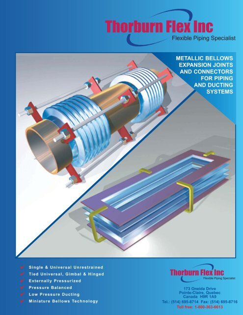
METALLIC BELLOWS<br />
EXPANSION JOINTS<br />
AND CONNECTORS<br />
FOR PIPING<br />
AND DUCTING<br />
SYSTEMS<br />
✔<br />
✔<br />
✔<br />
✔<br />
✔<br />
✔<br />
Single & Universal Unrestrained<br />
Tied Universal, Gimbal & Hinged<br />
Externally Pressurized<br />
Pressure Balanced<br />
Low Pressure Ducting<br />
Miniature Bellows Technology<br />
<strong>Thorburn</strong> <strong>Flex</strong> <strong>Inc</strong><br />
<strong>Flex</strong>ible Piping Specialist<br />
173 Oneida Drive<br />
Pointe-Claire, Quebec<br />
Canada H9R 1A9<br />
Tel.: (514) 695-8714 Fax: (514) 695-8716<br />
Toll free: 1-800-363-6613
<strong>Thorburn</strong> <strong>Flex</strong> <strong>Inc</strong><br />
<strong>Flex</strong>ible Piping Specialist<br />
THORBURN’S EMPLOYMENT OF<br />
STATE-OF-THE-ART TECHNOLOGY<br />
<strong>Thorburn</strong> is an innovative manufacturer of specialized<br />
engineered flexible piping systems (i.e. custom hose<br />
assemblies and expansion joints). Since 1960, <strong>Thorburn</strong>’s<br />
corporate mission evolution and business philosophy have<br />
been customer driven and targeted to selected niche<br />
applications (in industries such as power generation, both<br />
fossel fuel and nuclear, pulp and paper, petrochemical,<br />
aluminium smelting, ship building, aerospace and<br />
pharmaceutical) where <strong>Thorburn</strong> can achieve clear positions<br />
of sustainable technological and market-share leadership.<br />
DESIGNING, BUILDING AND SUPPLYING<br />
THE WORLD’S FINEST<br />
EXPANSION JOINT AND CONNECTOR SYSTEMS<br />
<strong>Thorburn</strong>’s committment to development is<br />
reinforced through the use of CAD (Computer<br />
Aided Design) system technology and finite<br />
engineering analysis, which permits <strong>Thorburn</strong> to<br />
pinpoint potential critical areas and provide<br />
timely sound engineered solutions<br />
FOUNDER, Jack <strong>Thorburn</strong><br />
Bellows tubes prior to convolution<br />
forming<br />
<strong>Thorburn</strong>’s procedures<br />
and welders certified to<br />
ASME Sections III, VIII, IX<br />
using modern TIG<br />
welding technology<br />
<strong>Thorburn</strong>’s tied universal expansion<br />
joint system<br />
Shown is Jack <strong>Thorburn</strong>, who founded<br />
the company in 1954, enjoying one of his<br />
passions, cross-country skiing. Unfortunately<br />
Jack passed away on February<br />
16th 1995. He will be sorely missed. The<br />
company’s leadership passed to Jack’s<br />
eldest son Robert in September 1994.<br />
<strong>Thorburn</strong>’s Single-<strong>Flex</strong><br />
unrestrained expansion joint<br />
system<br />
<strong>Thorburn</strong>’s multi-ply <strong>Inc</strong>onel low stress<br />
high temperature/pressure custom<br />
bellows technology
THORBURN<br />
THE FLEXIBLE PIPING SPECIALIST<br />
EXPERIENCE YOU CAN DEPEND ON<br />
Since 1960, <strong>Thorburn</strong> has devoted its expanding facilities and engineering expertise to the design,<br />
development and manufacture of flexible piping systems. Integrally associated with this product mix are<br />
<strong>Thorburn</strong>’s metallic expansion joints and connectors for piping and ducting systems.<br />
<strong>Thorburn</strong>’s exclusive 24 hour field servicing<br />
and repairing by skilled craftsmen,<br />
technicians and engineers at your service.<br />
Large diameter roll forming of bellows<br />
Our sincerest thanks to the many<br />
valued customers who have<br />
purchased <strong>Thorburn</strong>’s flexible<br />
piping products over the years.<br />
We look forward to working<br />
together with you and meriting<br />
your continued support for many<br />
years to come.<br />
Robert <strong>Thorburn</strong><br />
President<br />
Welding and Fabrication Certification<br />
■ Welders and welding procedures:<br />
ASME Section IX, VIII, III<br />
■ GTAW, FCAW, TIG, MIG, core wire<br />
■ Tube welding, tack welding, automated<br />
flame cutting, large turn tables, rolls and<br />
positioners<br />
■ Roll forming up to 180” single or multi-ply<br />
■ Hydro forming up to 56” single or multi-ply<br />
Quality Assurance Certifications<br />
■ Commercial<br />
• CSA CAN3 Z299.1<br />
• ISO 9001<br />
• CSA B.51 (Category A&D)<br />
• ASME B31.1/B31.3/B31.5<br />
■ Nuclear<br />
• ASME CODE SECTION III<br />
subsection NCA 4000 (ASME-NQA-1)<br />
• CSA N-285.0<br />
■ Design and Materials<br />
• ASME code Sections I, II, III,<br />
VIII, IX, B31.1 and B31.3<br />
• EJMA 6th Edition<br />
Testing, NDT/NDE Programs and<br />
Design Verification Tests<br />
■ ASME Section V<br />
■ Magnetic particle, ultrasonic, Eddy current<br />
and dye penetrant testing<br />
■ Mass spectrometer and helium leak<br />
detection, radiography<br />
■ Hydro testing<br />
■ Burst testing up to 150,000 psi<br />
■ Bellows fatigue testing<br />
■ Seismic and vibration analysis<br />
■ Spring rate, dead weight and hardness<br />
testing<br />
<strong>Thorburn</strong>’s state-of-the-art TIG welding<br />
technology for externally pressurized<br />
expansion joint assembly<br />
Applications which employ<br />
<strong>Thorburn</strong>’s metallic<br />
expansion joint technology<br />
■ Power generating both fossil<br />
fuel and nuclear<br />
■ Gas turbines, diesel exhaust<br />
■ Petroleum refining and<br />
chemical processing<br />
■ Hot metal industries<br />
■ Ship building and marine<br />
■ Cogeneration<br />
■ Aviation and aerospace duct<br />
work<br />
■ Pulp and paper processing<br />
■ Heat exchangers<br />
■ Industrial piping systems<br />
■ Gas separation<br />
■ Water treatment<br />
Page 1
THORBURN<br />
FLEXIBLE PIPING SPECIALIST<br />
THORBURN'S METALLIC BELLOWS EXPANSION JOINTS AND CONNECTORS<br />
FOR PIPING AND DUCTING SYSTEMS<br />
METALLIC BRAIDED FLEX CONNECTORS Pages 28 to 29<br />
• Pipeline misalignment absorption<br />
• Lateral deflection and vibration absorption<br />
• Riser connections, pumps, compressors, cooling towers<br />
SINGLE AND UNIVERSAL (Unrestrained) Pages 31 to 52<br />
Single<br />
• <strong>Thorburn</strong>'s most economical<br />
expansion joint<br />
• Will not absorb pressure thrust<br />
forces unless control rods are<br />
used<br />
• Axial lateral offset limited and<br />
angular rotation<br />
• Generally used where axial or<br />
lateral movement is required and<br />
where anchoring is not a problem<br />
Universal<br />
• Used when axial and/or lateral concurrent movement<br />
requirements exceed <strong>Thorburn</strong>'s single bellows<br />
• Lack of control devices demands careful anchoring<br />
and guidance of connecting pipe<br />
HINGED ANGULAR ROTATION (Single plane) Page 32<br />
• Angular motion in only one plane<br />
• Positive control over bellows movement<br />
• Eliminates pressure thrust forces<br />
• Transmits external loads<br />
• Supports dead weight<br />
• Prevents torsion on bellows<br />
• No main anchors required<br />
• Minimum guiding required<br />
• Low forces on piping system<br />
• Maximum bellows cycle life<br />
• To be used in sets of two or three where<br />
piping changes direction. The hinge pins<br />
absorb internal pressure thrust, permitting<br />
the use of light anchors<br />
GIMBAL ANGULAR ROTATION (All planes) Page 33<br />
• Angular motion in all planes<br />
• Positive control over bellows movement<br />
• Eliminates pressure thrust forces<br />
• Transmits external loads<br />
• Supports dead weight<br />
• Prevents torsion on bellows<br />
• No main anchors required<br />
• Maximum bellows cycle life<br />
• Used in sets of two or three to<br />
absorb motion in any plane<br />
DOUBLE (In-line) Page 45<br />
• Use in-line on long pipe runs of straight piping to absorb major axial movement<br />
up to 12"<br />
• Joint is anchored in the center of the line, therefore two pipe guides must be<br />
placed on each side of the unit.<br />
Page 2
THORBURN<br />
FLEXIBLE PIPING SPECIALIST<br />
THORBURN'S METALLIC BELLOWS EXPANSION JOINTS AND CONNECTORS<br />
FOR PIPING AND DUCTING SYSTEMS<br />
TIED UNIVERSAL Pages 46 to 48<br />
• Absorbs large amounts of lateral movement in any direction<br />
• Eliminates pressure thrust loads<br />
• Absorbs thermal growth of the piping between tie rod attachments<br />
• Can support dead weight and centerspool<br />
• Eliminates main anchors<br />
• Minimum guiding<br />
• Typically used in a change in direction of piping to absorb expansion in both ways<br />
EXTERNALLY PRESSURIZED Pages 53 to 63<br />
• Long axial movements<br />
• High pressure/temperature capabilities<br />
• Self-draining convolutions<br />
• Integral cover and liner<br />
• Leakproof/No packing<br />
PRESSURE BALANCED (Elbow series) Pages 67 to 68<br />
• Absorbs axial and lateral movements while still restraining pressure thrust forces<br />
• Eliminates main anchors<br />
• Minimum guiding required<br />
IN-LINE PRESSURE BALANCED Page 69<br />
Universal series<br />
• Eliminates pressure<br />
thrust forces<br />
• Conserves space<br />
• Eliminates main anchors<br />
• Does not require a change in direction of<br />
the piping system<br />
• Lower pressure axial movement<br />
Externally pressurized series<br />
• Eliminates main anchors<br />
• Long axial movements at high pressure<br />
• Self-draining convolutions<br />
• Integral cover and liner<br />
• Leakproof - Packless<br />
• Maintenance free<br />
• Eliminates pressure thrust forces<br />
DUCTFLEX (Low pressure series) Pages 70 to 79<br />
(Axial and lateral offset limited and angular rotation)<br />
• Typically used in low pressure high temperature ducting systems<br />
• Also used in diesel exhaust systems where high temperature low pressures<br />
are in conflict<br />
• Available in round and rectangular shapes<br />
• Deep convolutions allow for large movement low spring rolls<br />
MINIATURE NICKLE METAL BELLOWS SERIES Page 80<br />
Page 3
THORBURN<br />
FLEXIBLE PIPING SPECIALIST<br />
TABLE OF CONTENTS<br />
GENERAL INFORMATION<br />
Why use <strong>Thorburn</strong>'s metal bellows type expansion joints? .... 5<br />
Accessories ......................................................................... 6-7<br />
Standard flange data .............................................................. 8<br />
Corrosion resistance reference table ................................ 9-11<br />
Bellows material data & common metallurgical problems .... 12<br />
How to interpret <strong>Thorburn</strong>'s bellows design<br />
analysis documentation ..................................................... 13<br />
<strong>Thorburn</strong>'s metal bellows design elements ..................... 14-15<br />
<strong>Thorburn</strong> expansion joints in piping systems ................. 16-17<br />
Anchor, guide and support ............................................. 18-19<br />
Pipe guide spacing table ...................................................... 20<br />
<strong>Expansion</strong> joint standard symbols ....................................... 20<br />
Thermal expansion data ...................................................... 21<br />
Typical design specifications ........................................... 22-23<br />
Salient building process ....................................................... 24<br />
Specification data sheet for metal bellows expansion joint .. 25<br />
Installation instructions ......................................................... 26<br />
Safety and design recommendations ................................... 27<br />
METALLIC FLEX CONNECTORS<br />
<strong>Metallic</strong> braided <strong>Flex</strong> connectors - Introduction .................... 28<br />
Pump/compressor connector threaded and welded............. 29<br />
"9617PA" flanged pump connector ....................................... 29<br />
Typical metallic expansion joint applications<br />
for piping systems ............................................................. 30<br />
SINGLE-FLEX<br />
Single-<strong>Flex</strong> Model "SF" ........................................................ 31<br />
Hing-<strong>Flex</strong> Series "HF" .......................................................... 32<br />
Gim-<strong>Flex</strong> Series "GF" ........................................................... 33<br />
Single-<strong>Flex</strong> Model "SF" ........................................................ 34<br />
Single-<strong>Flex</strong> Model "SF" - How to order ................................ 35<br />
Single-<strong>Flex</strong> Model "SF" specifications ............................. 36-43<br />
DUAL-FLEX<br />
Dual-<strong>Flex</strong> "DFU" ................................................................... 44<br />
Dual-<strong>Flex</strong> "DFP" ................................................................... 45<br />
Dual-<strong>Flex</strong> "DFT" .............................................................. 46-47<br />
Dual-<strong>Flex</strong> Model "DF" ........................................................... 48<br />
Dual-<strong>Flex</strong> - How to order ...................................................... 49<br />
Dual-<strong>Flex</strong> specifications .................................................. 50-52<br />
EXTRA-FLEX<br />
Extra-<strong>Flex</strong> Model "ESF/EFD" - Introduction .................... 53-55<br />
How to order Extra-<strong>Flex</strong> ....................................................... 56<br />
Extra-<strong>Flex</strong> Model "ESF/EFD" specifications .................... 57-63<br />
COMP-FLEX<br />
Comp-<strong>Flex</strong> durable expansion compensators ...................... 64<br />
Comp-<strong>Flex</strong> HPC Series ................................................... 65-66<br />
PRESSURE BALANCED EXPANSION JOINTS<br />
Pressure balanced elbow exp. joints<br />
"PBES" and "PBEU" ..................................................... 67-68<br />
In-line pressure balanced universal "IPBU"<br />
externally pressurized "IPBE" .......................................... 69<br />
DUCTFLEX<br />
Ductflex round Series "SDF" - Introduction .......................... 70<br />
Ductflex - How to order ........................................................ 71<br />
Ductflex specifications ..................................................... 72-74<br />
Angle flange data ................................................................. 75<br />
Ductflex rectangular - Introduction .................................. 76-77<br />
Ductflex rectangular Single-<strong>Flex</strong> specifications .................... 78<br />
Ductflex universal Dual-<strong>Flex</strong> Series "DFRU" and "DFRV" .... 79<br />
MINIATURE BELLOWS<br />
Miniature nickle metal bellows Series TMB .......................... 80<br />
HOT-FLEX<br />
Heavy duty teflon lined metal expansion joint system ........ 81<br />
Hot-flex “HF” construction details ....................................... 82<br />
Page 4
THORBURN<br />
FLEXIBLE PIPING SPECIALIST<br />
WHY USE THORBURN'S METAL BELLOWS<br />
TYPE EXPANSION JOINTS?<br />
All piping or ducting systems are subjected to changes in their geometry due to various factors, some of which are:<br />
a) Thermal:<br />
i.e. • Startup to operating temp.<br />
• Variations in ambient temp.<br />
• Emergency or fault conditions<br />
b) Pressure:<br />
i.e. • Deformation, due to constant pressure<br />
• Deformation, due to pulsating pressure<br />
• Deformation, due to vibration<br />
c) Mechanical:<br />
i.e. • Movement of other<br />
equipment<br />
• Thermal growth in<br />
other equipment<br />
Where the incorporation of sufficient natural flexibility in such a<br />
piping or ducting becomes a problem, three basic alternative<br />
solutions are open to the systems analyst.<br />
1) The expansion loop<br />
2) The slip type expansion joint<br />
3) <strong>Thorburn</strong> bellows type expansion joint<br />
1) EXPANSION LOOPS<br />
The "loop" is the oldest method of dealing with pipe movement<br />
and probably the most expensive when one considers today's<br />
high costs of material and labour. In addition, pressure drops,<br />
heat loss, high anchor loading together with the large space<br />
requirement, can make this method economically unsound for<br />
the relatively small amount of movements that can be<br />
accommodated with the pipe loop.<br />
3) HOW A THORBURN METALLIC BELLOWS WORKS<br />
<strong>Thorburn</strong>'s metallic bellows is a flexible seal. The convoluted<br />
portion of an expansion joint is designed to flex when thermal<br />
movements occur in the piping system. The number of convolutions<br />
depends upon the amount of movement the bellows must<br />
accommodate or the force that must be used to accomplish<br />
this deflection.<br />
The convoluted element must be strong enough circumferentially<br />
to withstand the line pressure of the system, yet responsive<br />
enough longitudinally to flex. The longitudinal load (pressure<br />
thrust) must then be absorbed by some other type of device.<br />
These are usually anchors, tie rods, hinges, or Gimbal structures.<br />
Pressure thrust can be calculated by multiplying the effective<br />
area shown in the catalogue by the working pressure.<br />
2) SLIP TYPE EXPANSION JOINTS<br />
Derived from the "Stuffing Box", the slip type expansion joint is<br />
an improvement on the <strong>Expansion</strong> Loop but is somewhat limited<br />
in its applications, being suitable for axial motion only. Small<br />
amounts of lateral or angular displacement will cause binding<br />
and eventually premature leakage. The design of this product is<br />
such that a regular examination and maintenance program must<br />
be introduced so that if leakage occurs, packing is tightened or<br />
replaced.<br />
In most cases the initial cost of the Slip type expansion joint<br />
greatly exceeds that of the Bellows expansion joint designed for<br />
the same application. Another factor to be considered is maintenance<br />
costs of Bellows type vs. the Slip type, as the bellows type<br />
requires no maintenance once correctly installed.<br />
Graphic illustration<br />
of <strong>Thorburn</strong>'s<br />
tied universal expansion joint<br />
BELLOWS MOVEMENTS<br />
BELLOWS TYPICAL SHAPES<br />
Types of bellows movement Principle for operation of Toroidal shape, extremely Lyre shape, pressure<br />
a bellows corrugation pressure resistant resistant and flexible<br />
Collars<br />
Axial Angular Lateral<br />
Page 5
THORBURN<br />
FLEXIBLE PIPING SPECIALIST<br />
ACCESSORIES<br />
LINERS<br />
Liners or interval sleeves should be specified for expansion joints under the following conditions:<br />
1. When pressure drop must be held to a minimum and smooth flow is desired.<br />
2. When flow velocities are high and flow induced vibration could prove harmful to the bellows.<br />
<strong>Thorburn</strong> recommends the use of liners where the flow velocities exceed the following values:<br />
Air, steam and other gases:<br />
a) Up to 6" diameter - 4 ft/sec. per inch of diameter.<br />
b) Over 6" diameter - 25 ft/sec.<br />
Water and other liquids:<br />
a) Up to 6" diameter - 1-2/3 ft/sec. per inch of diameter<br />
b) Over 6" diameter - 10 ft/sec.<br />
Typical Standard<br />
<strong>Expansion</strong> Joint<br />
3. When turbulent flow is generated upstream of the expansion joint, heavy gauge liners are<br />
required.<br />
4. When there is a possibility of erosion, such as in lines carrying catalyst or other abrasive<br />
materials, heavy gauge sleeves should be used.<br />
5. When there is reverse flow, heavy gauge sleeves should be used and weep holes provided in<br />
the liner.<br />
6. When extremely high temperatures are present. liners produce an air barrier which will<br />
decrease the operating temperature of the bellows.<br />
COVERS<br />
<strong>Thorburn</strong>'s covers should be specified when the following conditions prevail:<br />
Typical Vanstone<br />
<strong>Expansion</strong> Joint<br />
1. When there is a possibility of accidental damage to the bellows element during<br />
shipment, installation or while in service.<br />
2. When welding is going to be done in the immediate vicinity of the bellows and<br />
there is a posibility of weld splatter or arc strikes hitting the bellows element.<br />
3. When the expansion joint is going to be externally insulated. Note: one end of the<br />
cover must be left free to permit movement of the bellows, and the insulation used should be free from any substance which<br />
could prove harmful to the bellows material in the event of leaching.<br />
In the case of Extra-<strong>Flex</strong>, the cover is provided as an integral part of the expansion joint and serves as a protection for personnel in the<br />
event of a bellows failure.<br />
PURGE CONNECTIONS<br />
Purge connections are used in conjuction with internal liners to:<br />
1. Prevent packing or collection of solids in the area between<br />
the liner and the bellows.<br />
2. Introduce a cooling media, usually air or steam, between the<br />
bellows and the liner in high temperature service.<br />
LIMIT RODS<br />
Limit rods are used to limit over-compression and/or over-extension of the<br />
bellows element. Limit rods have no function under normal operating conditions.<br />
In the event of anchor failure the limit rod functions as a tie rod and<br />
contains the pressure thrust forces. This safety device prevents damage to<br />
piping, equipment and personnel.<br />
Page 6
THORBURN<br />
FLEXIBLE PIPING SPECIALIST<br />
ACCESSORIES<br />
CONTROL RODS<br />
Control rods are utilized to prevent excessive displacement of the bellows in a<br />
universal expansion joint. These rods also control the relatively free centerspool<br />
between the two bellows. These rods are not designed to restrain pressure<br />
thrust forces.<br />
TWO-PLY TESTABLE EXPANSION JOINT<br />
The purpose of the 2-ply testable bellows is to provide a safety ply design. Each<br />
bellows ply is designed to withstand the system design pressure independently,<br />
so that in the event one ply fails for any reason, the remaining ply will enable the<br />
expansion joint to continue to function in a normal condition. The space between<br />
the bellows plies can be connected to a pressure gauge or a continuous<br />
monitoring system. It would register any change in pressure and thus trigger<br />
action to program replacement of the expansion joint on a routine basis.<br />
TOROIDAL EXPANSION JOINT<br />
Toroidal expansion joints are used in very high pressure systems. This type of<br />
construction transmits most of the hoop loading from the convolutions to the<br />
adjacent rings. This design allows relatively thin bellows to accept very high<br />
pressures.<br />
MULTI-PLY BELLOWS<br />
Multi-ply bellows construction is used when increased fatigue life and lower forces<br />
are required while still maintaining the same pressure capacity. The multiple plies<br />
act in unison as far as hoop pressure loading is concerned, but act individually<br />
when fatigue life and forces are calculated. <strong>Thorburn</strong> can also manufacture multiply<br />
bellows with varying materials. This is especially useful when the media dictates<br />
a material for corrosion protection, but one that is not strong enough to take the<br />
pressure loading. This type of construction allows <strong>Thorburn</strong> to supply the most<br />
economic bellows of optimum design for any individual application. Small holes<br />
are drilled into the outer ply cuffs of a multi-ply bellows to provide for expansion of<br />
entrapped air between the plies during high temperature operation.<br />
HEAVY WALL BELLOWS<br />
As a result of significantly improved fabrication capabilities, <strong>Thorburn</strong> now offers heavy wall single ply bellows to 3/16 of an inch (.187<br />
inches, 4.76 mm) thickness and convolution heights ranging to 15 inches. These bellows possess reasonable spring forces as a result<br />
of the high convolution configuration.<br />
Bellows of this thickness quite often enable maintenance personnel to make temporary weld repairs, in many cases without system<br />
shutdown. Such repairs might allow the system to continue to operate until a regularly scheduled shutdown occurs.<br />
Heavy wall bellows are less susceptible to damage during installation and systems start-up. Multiple-ply bellows are available to a<br />
thickness of 1/4 inch (.250 inches – 6.35 mm).<br />
Page 7
THORBURN<br />
FLEXIBLE PIPING SPECIALIST<br />
STANDARD FLANGE DATA<br />
This abbreviated flange data summary is intended to help system designers in selecting the optimum pipe and duct flanges. The<br />
working pressure at temperature ratings were obtained from applicable flange specifications. Where elevated temperature data was not<br />
available, the rated working pressure at ambient was downrated in accordance with ASME Code strength versus temperature correction<br />
factors.<br />
Slip-On Flanges Nominal Working Pressure Rating (psi) at Temperature (Deg. F)<br />
I.D. (in.) -20º to 100º 200º 300º 400º 500º 600º 700º 800º<br />
Class 125 L.W. 6 - 12 175 152 134 116 98 80 62 46<br />
forged steel Mat'l A-105<br />
AWWA 125 L.W. 14 - 96 150 131 115 99 83 67 51 38<br />
C207-54T Class D Mat'l A-105<br />
150# forged steel 1 - 24 275 260 230 200 170 140 110 80<br />
ANSI B16.5 Mat'l A-105<br />
Class 125 forged steel 26 - 96 275 240 210 180 150 130 110 80<br />
dimensions to B16.1 Mat'l A-105<br />
Class 125 (Class A) 1 - 12 175 165 140<br />
cast steel B16.1 Mat'l 126A<br />
Class 125 (Class B) 1 - 12 200 190 165 140<br />
Cast steel B16.1 14 - 24 150 135 110<br />
Mat'l A-126B 30 - 48 150 115 50<br />
Class 300 forged steel 1 - 24 740 675 655 635 600 550 535 410<br />
ANSI B16.5 Mat'l A-105<br />
Class 400 forged steel 1 - 24 990 900 875 845 800 730 710 550<br />
ANSI B16.5 Mat'l A-105<br />
The dimensions data shown below have been consolidated from current standards for easy reference<br />
Nom.<br />
Size<br />
(in.)<br />
CLASS 125 L.W. CLASS 150 B16.5 CLASS 300 B16.5<br />
O.D. T L BC #H HD WT O.D. T L BC #H HD WT O.D. T L BC #H HD WT<br />
LBS LBS LBS<br />
1.5 5.00 0.688 0.875 3.875 4 0.625 3 6.125 0.813 1.188 4.500 4 0.875 6<br />
2.0 6.00 0.750 1.000 4.750 4 0.750 5 6.500 0.875 1.313 5.000 8 0.750 7<br />
2.5 7.00 0.875 1.125 5.500 4 0.750 7 7.500 1.000 1.500 5.875 8 0.875 10<br />
3.0 7.50 0.938 1.188 6.000 4 0.750 8 8.250 1.125 1.688 6.625 8 0.875 13<br />
3.5 8.50 0.938 1.250 7.000 8 0.750 11 9.000 1.188 1.750 7.250 8 0.875 17<br />
4.0 9.00 0.938 1.313 7.500 8 0.750 13 10.000 1.250 1.875 7.875 8 0.875 22<br />
5.0 10.00 0.938 1.438 8.500 8 0.875 15 11.000 1.375 2.000 9.250 8 0.875 28<br />
6.0 11 0.563 1.25 9.50 8 0.875 13 11.00 1.000 1.563 9.500 8 0.875 19 12.500 1.438 2.063 10.625 12 0.875 39<br />
8.0 13.5 0.563 1.25 11.75 8 0.875 18 13.50 1.125 1.750 11.750 8 0.875 30 15.000 1.625 2.438 13.000 12 1.000 58<br />
10.0 16 0.688 1.25 14.25 12 1 26 16.00 1.188 1.938 14.250 12 1.000 43 17.500 1.875 2.625 15.250 16 1.125 81<br />
12.0 19 0.688 1.25 17.00 12 1 42 19.00 1.250 2.188 17.000 12 1.000 64 20.500 2.000 2.875 17.750 16 1.250 115<br />
14.0 21 0.750 1.25 18.75 12 1.125 44 21.00 1.375 2.250 18.750 12 1.125 90 23.000 2.125 3.000 20.250 20 1.250 165<br />
16.0 23.5 0.750 1.25 21.25 16 1.125 58 23.50 1.438 2.500 21.250 16 1.125 98 25.500 2.250 3.250 22.500 20 1.375 190<br />
18.0 25 0.750 1.25 22.75 16 1.250 59 25.00 1.563 2.688 22.750 16 1.250 130 28.000 2.375 3.500 24.750 24 1.375 250<br />
20.0 27.5 0.750 1.25 25.00 20 1.250 69 27.50 1.688 2.875 25.000 20 1.250 165 30.500 2.500 3.750 27.000 24 1.375 315<br />
22.0 29.5 1.000 1.75 27.25 20 1.375 76 29.50 1.813 3.125 27.250 20 1.375 185 — — — — —<br />
24.0 32 1.000 1.75 29.50 20 1.375 115 32.00 1.875 3.250 29.500 20 1.375 220 36.000 2.750 4.188 32.000 24 1.625 475<br />
26.0 34.25 1.000 1.75 31.75 24 1.375 125<br />
CLASS 125 B16.1<br />
28.0 36.5 1.000 1.75 34.00 28 1.375 140 36.50 2.063 3.438 34.000 28 1.375 270<br />
30.0 38.75 1.000 1.75 36.00 28 1.375 150 38.75 2.125 3.500 36.000 28 1.375 305<br />
32.0 41.75 1.125 1.75 38.50 28 1.625 205<br />
34.0 43.75 1.125 1.75 40.50 32 1.625 215<br />
#H & H.D.<br />
36.0 46 1.125 1.75 42.75 32 1.625 235 46.00 2.375 3.750 42.750 32 1.625 450<br />
40.0 50.75 1.125 1.75 47.25 36 1.625 280<br />
42.0 53 1.250 1.75 49.50 36 1.625 330 53.00 2.625 4.000 49.500 36 1.625 650<br />
48.0 59.5 1.375 2.50 56.00 44 1.625 425 59.50 2.750 4.125 56.000 44 1.625 800<br />
O.D.<br />
T<br />
54.0 66.25 1.375 2.50 62.75 44 1.875 500 66.25 3.000 4.375 62.750 44 1.875 1025<br />
60.0 73 1.500 2.75 69.25 52 1.875 640 73.00 3.125 4.500 69.250 52 1.875 1250 B.C.<br />
66.0 80 1.500 2.75 76.00 52 1.875 750 80.00 3.375 4.875 76.000 52 1.875 1775<br />
72.0 86.5 1.500 2.75 82.50 60 1.875 850 86.50 3.500 5.000 82.500 60 1.875 1925<br />
L<br />
84.0 99.75 1.750 3.00 95.50 64 2.125 1000 99.75 3.875 5.375 95.500 64 2.125 2600<br />
96.0 113.25 2.000 3.25 108.50 68 2.375 1650 113.25 4.250 5.750 108.500 68 2.375 3275<br />
Page 8
THORBURN<br />
FLEXIBLE PIPING SPECIALIST<br />
CORROSION RESISTANCE REFERENCE TABLE<br />
Rating Code:<br />
A - Suitable (normal conditions)<br />
B - Limited Service<br />
C - Unsuitable<br />
Notes:<br />
1 - Susceptible to intergranular corrosion<br />
2 - May cause explosive reaction<br />
3 - Susceptible to stress corrosion cracking<br />
4 - Susceptible to pitting type corrosion<br />
5 - Discolours<br />
6 - Concentration over 50 % and/or temperature over 200ºF, contact<br />
<strong>Thorburn</strong> with application details<br />
MEDIA<br />
CUPRO NICKEL 706<br />
MONEL 400<br />
INCONEL 625<br />
321 STAINLESS<br />
316 STAINLESS<br />
MEDIA<br />
CUPRO NICKEL 706<br />
MONEL 400<br />
INCONEL 625<br />
321 STAINLESS<br />
316 STAINLESS<br />
Acetaldehyde A A A A A<br />
Acetanilide B B B B B<br />
Acetic acid B B A B1 A1<br />
Acetic anhydride B B A B B<br />
Acetone A A A B B<br />
Acetophenone A A A B B<br />
Acetylene C A A A A<br />
Acrylates B B B B B<br />
Acrylic acid B B A B B<br />
Acrylonitrile A A A A A<br />
Alcohols A A A A A<br />
Alum B B A B B<br />
Alumina A A A A A<br />
Aluminium acetate B B B B B<br />
Aluminium chloride (Dry) B A A A A<br />
Aluminium chloride (Moist) C B A C3,4 C3<br />
Aluminium fluoride B B C C C<br />
Aluminium hydroxide A B B B B<br />
Aluminium sulfate B B B B1,3 A3<br />
Ammonia (Dry) A A A A A<br />
Ammonia (Moist) C C B A A<br />
Ammonium acetate B A A A A<br />
Ammonium bromide C B B C4 C4<br />
Ammonium chloride (Dry) C A A A A<br />
Ammonium chloride (Moist) C B B C3,4 C3<br />
Ammonium hydroxide C A A B B<br />
Ammonium nitrate C C2 B B3 B3<br />
Ammonium sulfate C B C C1 B<br />
Amyl acetate A A A A A<br />
Amyl alcohol A A A A A<br />
Amyl chloride (Dry) C A A A A<br />
Amyl chloride (Moist) C B C C3,4 C3<br />
Aniline C A B B B<br />
Aniline dyes C A B B B<br />
Asphalt A A A A A<br />
Atmosphere (Industrial) A A A B4 A4<br />
Atmosphere (Marine) A A A B4 B4<br />
Atmosphere (Rural) A A A A A<br />
Barium carbonate A B B B B<br />
Barium chloride (Dry) B A A A A<br />
Barium chloride (Moist) C B C C3,4 C3<br />
Barium hydroxide A B B B A<br />
Barium sulfate B B B B B<br />
Barium sulfide C C B B B<br />
Beer A A A A A<br />
Beet sugar syrups A A A A A<br />
Benzaldehyde A B B B B<br />
Benzene (benzol) A A A A A<br />
Benzoic acid A B A A A<br />
Benzylamine C B B B B<br />
Benzyl chloride (Dry) A A A A A<br />
Benzyl chloride (Moist) B B B C,3,4 C,3<br />
Black liquor, sulfate process C A B B B<br />
Bleaching powder (Dry) A A A A A<br />
Bleaching powder (Moist) B B B C1,3,4 C3,4<br />
Borax A A A A A<br />
Bordeaux mixture A A A A A<br />
Boric acid A B A A A<br />
Boron trichloride (Dry) B B B B B<br />
Boron trichloride (Moist) B B C C3,4 C3<br />
Boron trifluoride (Dry) A B A B B<br />
Brines A B B C3,4 C3<br />
Bromic acid C C C C C<br />
Bromine (Dry) A A A B B<br />
Bromine (Moist) B B B C C<br />
Butadiene A A A A A<br />
Butane A A A A A<br />
Butanol (butyl alcohol) A A A A A<br />
Butyl phenols B A B B B<br />
Butylamine B A A A A<br />
Butyric acid A B A B B<br />
Cadmium chloride (Moist) B B B C3,4 C3<br />
Cadmium chloride (Dry) A A A A A<br />
Cadmium sulfate A A A A A<br />
Calcium bisulfite B B B B1 B<br />
Calcium bromide A B A C3 C3<br />
Calcium chloride (Moist) A B A C3,4 C3<br />
Calcium chloride (Dry) A A A A A<br />
Calcium fluoride B B B C C<br />
Calcium hydroxide A B A B B<br />
Calcium hypochlorite (Moist) B B B C3,4 C3,4<br />
Calcium hypochlorite (Dry) A A A A A<br />
Calcium nitrate B B A B1 B<br />
Calcium oxide A A A A A<br />
Cane sugar syrups A A A A A<br />
Carbolic acid (Phenol) B B B B B<br />
Carbon dioxide (Dry) A A A A A<br />
Carbon dioxide (Moist) B A A A A<br />
Carbonated beverages B A A A A<br />
Carbonated water B A A A A<br />
Carbon disulfide B B B B B<br />
Carbon tetrachloride (Dry) A A A A A<br />
Carbon tetrachloride (Moist) B B B C3,4 C4<br />
Castor oil A A A A A<br />
Chlorine (Dry) A A A A A<br />
Chlorine (Moist) C B C C3,4 C3<br />
Page 9
THORBURN<br />
FLEXIBLE PIPING SPECIALIST<br />
CORROSION RESISTANCE REFERENCE TABLE (cont'd)<br />
MEDIA<br />
CUPRO NICKEL 706<br />
MONEL 400<br />
INCONEL 625<br />
321 STAINLESS<br />
316 STAINLESS<br />
MEDIA<br />
CUPRO NICKEL 706<br />
MONEL 400<br />
INCONEL 625<br />
321 STAINLESS<br />
316 STAINLESS<br />
Chloroacetic acid B B B C3,4 C3<br />
Chloric acid C C C C3 C3<br />
Chlorine dioxide (Moist) C B B C3,4 C3<br />
Chlorine dioxide (Dry) B A A A A<br />
Chloroform (Dry) A A A A A<br />
Chloroform (Moist) B B B C3,4 C3<br />
Chromic acid C C B C1,4 C<br />
Chromic fluoride C B B C C<br />
Chromic hydroxide B B B B B<br />
Chromium sulfate B B B B B<br />
Cider A A A A A<br />
Citric acid A B A B B<br />
Coffee A A A A A<br />
Copper chloride (Dry) A A A A A<br />
Copper chloride (Moist) C B C C3,4 C3<br />
Copper nitrate C C B A A<br />
Copper sulfate B B B B1 B<br />
Corn oil A A A A A<br />
Cottonseed oil A A A A A<br />
Creosote A A A A A<br />
Crude oil B A A C1 B<br />
Cyclohexane B B B B B<br />
DDT B B4 B B B<br />
Dichloroethane (Dry) A A A A A<br />
Dichloroethane (Wet) B B B C4 C4<br />
Dichloroethylene (Dry) A A A A A<br />
Dichloroethylene (Moist) B B B C4 C4<br />
Dichlorophenol B B B B3 B3<br />
Disocyanate A A A A A<br />
Dimethyl sulfate B B A B B<br />
Epichlorohydrin (Dry) A A A A A<br />
Epichlorohydrin (Moist) B B B C3,4 C3<br />
Ethane A A A A A<br />
Ethers A A A A A<br />
Ethyl acetate A B A B B<br />
Ethyl alcohol A A A A A<br />
Ethyl benzene B B A B3 B<br />
Ethyl chloride (Moist) B B B C3,4 C3<br />
Ethyl chloride (Dry) A A A A A<br />
Ethylene A A A A A<br />
Ethylene chlorohydrin (Dry) A A A A A<br />
Ethylene chlorohydrin (Moist) B B B C4 C4<br />
Ethylene diamine B B A B B<br />
Ethylene glycol A A A A A<br />
Ethylene oxide C B B B B<br />
Fatty acids B B B B1,4 A<br />
Ferric chloride (Moist) C B B C1,3,4 C3,4<br />
Ferric chloride (Dry) A A A A A<br />
Ferric nitrate C C B B B<br />
Ferric sulfate C C B B1 A<br />
Ferrous chloride (Moist) C B B C3,4 C3<br />
Ferrous chloride (Dry) A A A A A<br />
Ferrous sulfate B A B B4 B<br />
Fluorine (Dry) A A A A A<br />
Fluorine (Moist) C B C C C<br />
Formaldehyde A A5 B B B<br />
Formic acid A B A B1 A<br />
Freon A A A A A<br />
Fruit juices B A A A A<br />
Fuel oil A A A A A<br />
Furfural A A B A A<br />
Gasoline A A A A A<br />
Gelatine A A A A A<br />
Glucose A A A A A<br />
Glue A A A A A<br />
Glutamic acid B B A B3,4 B3,4<br />
Glycerin (glycerol) A A A A A<br />
Heptane A A A A A<br />
Hexachloroethane (Dry) A A A A A<br />
Hexachloroethane (Moist) B B B C4 C4<br />
Hydrazine C C A A A<br />
Hydrobromic acid C C B C4 C<br />
Hydrocarbons (Pure) A A A A A<br />
Hydrochloric acid C B C C4 C4<br />
Hydrocyanic acid C B B B1 B<br />
Hydrofluoric acid C B B C1,3 C<br />
Hydrofluorsilicic acid B B B C C<br />
Hydrogen A A A A A<br />
Hydrogen chloride (Dry) A A A A A<br />
Hydrogen chloride (Wet) C B C C4 C4<br />
Hydrogen peroxide B B A A A<br />
Hydrogen sulfide (Dry) A A A A A<br />
Hydrogen sulfide (Moist) C B B B4 A<br />
Hydroquinone B B B B B<br />
Kerosine (Kerosene) A A A A A<br />
Lacquers A A A A A<br />
Lacquer solvents A A A A A<br />
Lactic acid A B B B1,4 B1<br />
Lime A A A A A<br />
Lime (Sulfur) C B B B B<br />
Linseed oil B A A A A<br />
Lithium chloride (Moist) C B B C3,4 C3<br />
Lithium chloride (Dry) A A A A A<br />
Lithium hydroxide B B B B B<br />
Magnesium chloride (Moist) B B B C3,4 C3<br />
Magnesium chloride (Dry) A A A A A<br />
Magnesium hydroxide A A A A A<br />
Magnesium sulfate A A A B A<br />
Maleic acid C B B B1 B<br />
Mercuric chloride (Moist) C B A C3,4 C3<br />
Mercuric chloride (Dry) C A A A A<br />
Mercurous nitrate C B3 B B B<br />
Mercury C B3 B B B<br />
Methyl alcohol A A A A A<br />
Methane A A A A A<br />
Methyl chloride (Dry) A A A A A<br />
Methyl chloride (Moist) B B B C3,4 C3<br />
Methyl ethyl ketone A B A B B<br />
Page 10
THORBURN<br />
FLEXIBLE PIPING SPECIALIST<br />
CORROSION RESISTANCE REFERENCE TABLE (cont'd)<br />
MEDIA<br />
CUPRO NICKEL 706<br />
MONEL 400<br />
INCONEL 625<br />
321 STAINLESS<br />
316 STAINLESS<br />
MEDIA<br />
CUPRO NICKEL 706<br />
MONEL 400<br />
INCONEL 625<br />
321 STAINLESS<br />
316 STAINLESS<br />
Milk A A A A A<br />
Mine water C B A B B<br />
Naphthalene B B A A A<br />
Natural gas A A A A A<br />
Nickel chloride (Moist) B B B C3,4 C3<br />
Nickel chloride (Dry) A A A A A<br />
Nitric acid C C B A A<br />
Nitrotoluene B B B B B<br />
Nitrogen A A A A A<br />
Oleic acid B A B B4 B<br />
Oleum (Fuming H 2<br />
S0 4<br />
) C C B B B<br />
Oxalic acid A B B C1 B1<br />
Oxygen A A A A A<br />
Palmitic acid B A A A A<br />
Parafin A A A A A<br />
Pentane B B B B B<br />
Phosphoric acid B B B C1 B1<br />
Phthalic acid B B B B1 B<br />
Picric acid C C B B B<br />
Potassium bromide A B B C C<br />
Potassium carbonate A A A A A<br />
Potassium chloride (Moist) B B B C3,4 C3<br />
Potassium chloride (Dry) A A A A A<br />
Potassium chromate A B A B B<br />
Potassium cyanide C B B B B<br />
Potassium dichromate C A A A A<br />
Potassium fluoride C B B C C<br />
Potassium hydroxide B B3 A B3 B3<br />
Potassium nitrate A B A B A<br />
Potassium permanganate B B B B B<br />
Potassium sulfate A B A B B<br />
Propane A A A A A<br />
Propylene A A A A A<br />
Propylene dichloride (Dry) A A A A A<br />
Propylene dichloride (Moist) B B B C4 C4<br />
Pyridine B B B B B<br />
Pyrrolidine B B A B A<br />
Quinine B B A B B<br />
Rosin A A A A A<br />
Sea water A B A C3,4 C3<br />
Sewage A A A A A<br />
Silver salts C A A B B<br />
Silver nitrate C C A B B<br />
Soap solutions A A A A A<br />
Sodium A A A A A<br />
Sodium acetate B B B B4 B<br />
Sodium bicarbonate A A A A A<br />
Sodium bisulfate B B B B1,4 B<br />
Sodium bisulfite B B4 B B B<br />
Sodium bromide C B B C C<br />
Sodium carbonate A A A A A<br />
Sodium chlorate (Moist) B B B C3,4 C3<br />
Sodium chlorate (Dry) A A A A A<br />
Sodium chloride (Moist) A B A C3,4 C3<br />
Sodium chloride (Dry) A A A A A<br />
Sodium chromate B B B B B<br />
Sodium citrate B B B B B<br />
Sodium cyanide C B B B B<br />
Sodium dichromate C B B B B<br />
Sodium fluoride B B B C4 C<br />
Sodium hydroxide B3 B3 A B3 B3<br />
Sodium hypochlorite (Moist) C B B C1,4 C4<br />
Sodium hypochlorite (Dry) A A A A A<br />
Sodium metasilicate A A A A A<br />
Sodium nitrate A A A A A<br />
Sodium nitrite B B B B B<br />
Sodium peroxide B B B B B<br />
Sodium phosphate A A B B B<br />
Sodium silicate A A A A A<br />
Sodium sulfate A A A B3 B<br />
Sodium sulfide C B B B4 B<br />
Sodium sulfite B B B B B<br />
Sodium thiosulfate C B B B B<br />
Stannic chloride (Moist) C B B C3,4 C3<br />
Stannic chloride (Dry) A A A A A<br />
Stannous chloride (Moist) C B B C3,4 C3<br />
Stannous chloride (Dry) A A A A A<br />
Steam A A3 A A A<br />
Stearic acid B B B B B<br />
Strontium nitrate B B B B B<br />
Sulfate black liquor B B B B B<br />
Sulfate green liquor B B B B3 B3<br />
Sugar solutions A A A A A<br />
Sulfur (Dry) B A A A A<br />
Sulfur (Molten) C B A A A<br />
Sulfur chloride (Dry) A A A A A<br />
Sulfur chloride (Wet) B B B C3,4 C3<br />
Sulfur dioxide (Dry) B B B C1 B<br />
Sulfur dioxide (Moist) C C C C1 B<br />
Sulfur trioxide (Dry) A A A A A<br />
Sulfuric acid, 95-100% B B A A A<br />
Sulfuric acid, 80-95% B B B B B<br />
Sulfuric acid, 40-80% C C B C1 C1<br />
Sulfuric acid, 40% B C B C1 C1<br />
Sulfurous acid C B B C1,4 C1,4<br />
Tall oil B B B B B<br />
Tannic acid B B B B B<br />
Tar A A A A A<br />
Tartaric acid B B B B B<br />
Tetraphosphoric acid C C B B B<br />
Toluene A A A A A<br />
Trichloroacetic acid B B B C3,4 C4<br />
Trichloroethane (Dry) A A A A A<br />
Trichloroethane (Moist) B B B C4 C4<br />
Trichloroethylene (Dry) A A A A A<br />
Trichloroethylene (Moist) B B B C4 C4<br />
Turpentine A A A A A<br />
Varnish A A A A A<br />
Vinegar B B B B B<br />
Water (potable) A A A A A<br />
Xylene A A A A A<br />
Zinc chloride (Moist) C B B C3,4 C3<br />
Zinc chloride (Dry) A A A A A<br />
Zinc sulfate B B B B A<br />
Page 11
THORBURN<br />
FLEXIBLE PIPING SPECIALIST<br />
BELLOWS MATERIAL DATA<br />
<strong>Thorburn</strong> can supply bellows from most ductile materials which can be welded by the automatic TIG butt welding<br />
process and yield a homogeneous ductile weld structure.<br />
Companies specifying and purchasing <strong>Thorburn</strong> bellows must give careful consideration to the selection of bellows<br />
material. When in doubt, consult <strong>Thorburn</strong> with your specific application.<br />
MATERIAL CODES FOR BELLOWS (B), LINER (L), ENDS (E) AND SPOOL (S)<br />
<strong>Thorburn</strong> Material Code<br />
Bellows Liner End Spool Accessories<br />
Tie rods,<br />
(B) (L) (E) (S) nuts, etc.<br />
ASTM<br />
Material Designation<br />
Material Type<br />
B-0 L-0 E-0 S-0 A-0 A36/44W Carbon steel<br />
B-1 L-1 E-1 S-1 A-1 A-240 304<br />
B-2 L-2 E-2 S-2 A-2 A-240 304L<br />
B-3 L-3 E-3 S-3 A-3 A-240 316<br />
B-4 L-4 E-4 S-4 A-4 A-240 316L<br />
B-5 L-5 E-5 S-5 A-5 A-240 321<br />
B-6 L-6 E-6 S-6 A-6 A-240 309<br />
B-7 L-7 E-7 S-7 A-7 A-240 310<br />
B-8 L-8 E-8 S-8 A-8 B-127 Monel 400<br />
B-9 L-9 E-9 S-9 A-9 B-168 <strong>Inc</strong>onel 600<br />
B-10 E-10 E-10 E-10 A-10 B-443 <strong>Inc</strong>onel 625<br />
B-11 E-11 E-11 E-11 A-11 B-409 <strong>Inc</strong>oloy 800<br />
B-12 E-12 E-12 E-12 A-12 B-424 <strong>Inc</strong>oloy 825<br />
B-14 L-14 E-14 S-14 A-14 B-409 <strong>Inc</strong>oloy 800HT<br />
B-15 L-15 E-15 S-15 A-15 B-162 Nickel 201<br />
B-16 L-16 E-16 S-16 A-16 B-575 <strong>Inc</strong>o C276<br />
B-17 L-17 E-17 S-17 A-17 B-364 Tantalum<br />
B-18 L-18 E-18 S-18 A-18 — Titanium Gr. 1<br />
B-19 L-19 E-19 S-19 A-19 — Zirconium Gr. 702<br />
N/A L-20 E-20 S-20 A-20 A-285 Carbon steel<br />
N/A L-21 E-21 S-21 A-21 A-570 Carbon steel<br />
N/A L-22 E-22 S-22 A-22 B-588 Carbon steel<br />
N/A L-23 E-23 S-23 A-23 A-606 Corten A<br />
N/A L-24 E-24 S-24 A-24 A-516 Carbon steel<br />
B-X L-X E-X S-X A-X — Special - specify<br />
Special notes<br />
1) Use of these material codes as a suffix in the catalogue part number designate the bellows, liner, end connectors, spool and accessories material that<br />
will be supplied by <strong>Thorburn</strong>.<br />
2) Special note for flanges and pipes: when forged flanges or scheduled pipe are used, the same nomenclature symbols are used (i.e.: E2 or S6).<br />
3) ASME "SA" or "SB" materials are available upon request.<br />
4) All bellows material purchased by <strong>Thorburn</strong> is "mill annealed" in accordance with "A", "SA" or "SB" specifications. <strong>Thorburn</strong> does not perform any other<br />
heat treating operations before welding, after welding, before forming convolutions or after forming convolutions unless specified by purchaser. Heat<br />
treatment of bellows after forming convolutions can lower bellows' spring rate, "squirm" pressure and cycle life. <strong>Thorburn</strong> will cooperate with purchasers<br />
requiring heat treatment after forming to arrive at what effect the heat treatment will have on published bellows data.<br />
FAILURE MODE<br />
COMMON METALLURGICAL PROBLEMS<br />
CAUSE<br />
FREQUENTLY USED SOLUTION<br />
Chloride Stress<br />
Corrosion Cracking<br />
Carbide Precipitation<br />
Pitting Corrosion<br />
Chlorides acting on austenitic stainless<br />
steel bellows (T-304, T-316, T-321)<br />
Chromium carbides form in unstabilized<br />
stainless steels (T-304, T316) at high temperatures<br />
(over 700ºF) causing loss of corrosion<br />
resistance<br />
Galvanic action causing holes to form in a<br />
bellows, usually from acids<br />
Use a high nickel alloy like <strong>Inc</strong>onel-600 or<br />
<strong>Inc</strong>onel-625<br />
Use a stabilized stainless steel (T-321) or<br />
low carbon stainless steel (T-304L) or another<br />
high alloy material not affected by<br />
carbide precipitation<br />
Use a bellows material containing molybdenum<br />
(T-316, I-825, I-625) or one of the<br />
specialty materials such as Zirconium, Titanium<br />
or Tantalum<br />
Page 12
THORBURN<br />
FLEXIBLE PIPING SPECIALIST<br />
HOW TO INTERPRET THORBURN'S<br />
BELLOWS DESIGN ANALYSIS DOCUMENTATION<br />
All custom bellows designs should be documented to prove that the design has been analyzed to the proper code, the design<br />
is safe and mechanically stable, the cycle life is in accordance with the specification requirements and the important stress<br />
values have been satisfied. <strong>Thorburn</strong> bellows design analysis shows all the critical information in a summary format. This<br />
paper is offered to help a customer interpret the information that is shown on <strong>Thorburn</strong>'s bellows design analysis so the<br />
information is more meaningful.<br />
THORBURN REF: ABI-001-06/19/95 ITEM: 01 THORBURN EQUIPMENT INC.<br />
CUSTOMER REF: LTD-401<br />
SHEET __/__ OF __/__<br />
JUNE 19, 1995 REV 08-06-92<br />
PREPARED BY: LUCIAN BODOCAN<br />
APPROVED BY:KEN McCORMICK<br />
The bellows' effective area is the area of the<br />
bellows that creates pressure thrust when<br />
acted upon by the operating pressure. The<br />
system anchors and/or the hardware on the<br />
expansion joint must be designed to<br />
withstand pressure thrust at the operating<br />
and test conditions.<br />
Torsional spring rate is offered for those pipe<br />
stress analysts who are inputting bellows<br />
characteristics into a pipe stress program.<br />
Bellows are not generally designed for<br />
torsional movements. But, the torsional<br />
stiffness value can affect the output of a pipe<br />
stress analysis that includes a <strong>Thorburn</strong><br />
expansion joint.<br />
THORBURN SINGLE BELLOWS DESIGN ANALYSIS<br />
THIS EXPANSION JOINT DESIGN ANALYSIS WAS CALCULATED WITH THE DESIGN<br />
EQUATIONS STATED IN THE STANDARDS OF THE EXPANSION JOINT MANUFACTURER'S<br />
ASSOCIATION INC., SIXTH EDITION.<br />
CODE REQUIREMENT: ANSI B31.3<br />
DESIGN PRESSURE:<br />
256 PSI<br />
DESIGN TEMPERATURE:<br />
266 DEG. F<br />
BELLOWS MATERIAL:<br />
A240-T304<br />
ALLOWABLE STRESS:<br />
17,000 PSI<br />
MODULUS OF ELASTICITY:<br />
27,304,000 PSI<br />
WELD JOINT EFFICIENCY 0.85<br />
DESIGN MOVEMENT CONDITIONS<br />
COND AXIAL LATERAL ANGULAR S5 S6 CYCLES TYP<br />
A. 0.25 0.13 0.10 0.20 1.00 2.00 2515 179315 4780<br />
INSIDE DIAMETER:<br />
OUTSIDE DIAMETER:<br />
NUMBER OF CONVOLUTIONS:<br />
MATERIAL THICKNESS:<br />
NUMBER OF PLIES:<br />
FREE LENGTH OVER CONVOLUTIONS:<br />
7.250 IN<br />
8.500 IN<br />
14 CONS<br />
0.024 IN<br />
2 PLIES<br />
8.75 IN<br />
S2 (CIRCONFERENTIAL MEMBRANE STRESS DUE TO PRESSURE): 9,206 PSI<br />
S3 (MERIDIONAL MEMBRANE STRESS DUE TO PRESSURE): 1,598 PSI<br />
S4 (MERIDIONAL BENDING STRESS DUE TO PRESSURE): 25,051 PSI<br />
S5 (MERIDIONAL MEMBRANE STRESS DUE TO DEFLECTION): SEE TABLE ABOVE<br />
S6 (MERIDIONAL BENDING STRESS DUE TO DEFLECTION): SEE TABLE ABOVE<br />
S t (STRESS RANGE FOR PRIMARY DESIGN CONDITION): 200,485 PSI<br />
DESIGN CYCLE LIFE FOR PRIMARY DESIGN CONDITIONS: 3,000 CYCLES<br />
RATED CYCLE LIFE FOR PRIMARY DESIGN CONDITION:<br />
4,780 CYCLES<br />
MAXIMUM DESIGN PRESSURE BASED ON SQUIRM:<br />
AXIAL SPRING RATE:<br />
LATERAL SPRING RATE:<br />
ANGULAR SPRING RATE:<br />
TORSIONAL SPRING RATE:<br />
BELLOWS EFFECTIVE AREA:<br />
361 PSI<br />
1,220 LBS/IN<br />
1,500 LBS/IN<br />
167 IN LBS/DEG<br />
74,457 IN LBS/DEG<br />
49.30 SQ/IN<br />
The proposed design has this calculated cycle<br />
life at the specified conditions.<br />
There are two types of squirm or instability<br />
that can occur for internally pressurized<br />
bellows. One is called column squirm (similar<br />
to buckling of a column) and the other is called<br />
in-plane squirm (localized plastic deformation).<br />
<strong>Thorburn</strong> calculated the maximum<br />
design pressures based on the most<br />
conservative of the two methods. The value<br />
stated on the design analysis is the predicted<br />
squirm pressure with a safety factor of 2.25.<br />
<strong>Thorburn</strong>'s spring rate calculations are based<br />
on the elastic spring rate criteria from EJMA.<br />
This is the actual temperature that was used for the<br />
bellows design. For certain special applications such as<br />
refractory lined expansion joints, the bellows is designed<br />
for a lower temperature than the media.<br />
This is the allowable stress for the bellows material at<br />
the bellows design temperature.<br />
This is the modulus of elasticity of the bellows material at<br />
the design temperature which is used to calculate spring<br />
rate and column squirm pressure. The room temperature<br />
modulus of elasticity is used to calculate the deflection<br />
stresses (S5 & S6).<br />
The weld joint efficiency is 1.0 if the bellows' longitudinal<br />
weld is 100% radiographically examined in accordance<br />
with the specified code.<br />
The design movements create the deflection stresses that<br />
determine cycle life. One complete cycle is based upon<br />
moving the bellows from the neutral length to position 1,<br />
back through the neutral length to position 2 and then<br />
back to the neutral length.<br />
Material thickness is generally stated as the standard<br />
sheet gauge thickness.<br />
S2 (hoop stress) is an important membrane stress that<br />
runs circumferentially around the bellows. The value must<br />
be lower than the allowable stress for the bellows' material<br />
multiplied by the bellows' longitudinal weld joint efficiency.<br />
S4 (pressure bending) is an important bending stress<br />
that is located in the side wall of the convolution running<br />
in the longitudinal direction. It is the stress that makes a<br />
"U" shaped convolution balloon out into an omega shape.<br />
The value of (S3 + S4) must be lower than the allowable<br />
stress of the bellows’ material multiplied by material<br />
strength factor which is equal to 3.0 for bellows in the as<br />
formed condition (with cold work) and 1.5 bellows in the<br />
annealed condition (without cold work).<br />
S6 (deflection bending) is the primary bending stress<br />
influencing fatigue life. This stress runs in the longitudinal<br />
direction and is most severe in the side wall of the<br />
convolution near the crest of root. There is no upper limit<br />
on this stress. It is calculated based on elastic theory,<br />
and the value of S6 is generally far in excess of the yield<br />
strength of the bellows material. That means that a typical<br />
expansion joint bellows undergoes plastic strain during<br />
each stroke.<br />
This is the specified cycle life expectancy value as per<br />
EJMA, ANSI B31.3 Appendix X, ASME Section VIII or<br />
ASME Section III Equations.<br />
Page 13
THORBURN<br />
FLEXIBLE PIPING SPECIALIST<br />
THORBURN'S METAL BELLOWS DESIGN ELEMENTS<br />
1) PRESSURE THRUST<br />
The spring represents the axial spring rate of the bellows. The<br />
hydraulic piston represents the effect of the pressure thrust which<br />
the expansion joint can exert on the piping anchors or pressure<br />
thrust restraints (hinges, Gimbals, tie rods) which may be part of<br />
the expansion joint assembly. The area of the hydraulic cylinder<br />
would be the effective area of the bellows.<br />
Force on equipment or adjacent piping anchors "F" = (the effective<br />
area of the bellows) x (the working pressure) + (the spring<br />
rate of the bellows) x (the stroke of the bellows).<br />
The pressure thrust force would equal (the working pressure) x<br />
(the bellows effective area).<br />
The pressure thrust force is typically much higher than the spring<br />
force.<br />
<strong>Expansion</strong> joints designed for lateral offset or for angular motion<br />
are more complicated to model accurately. However, the effect of<br />
pressure thrust is the same.<br />
Working pressure<br />
acting on the effective<br />
area of the bellows<br />
2) CIRCUMFERENTIAL MEMBRANE STRESS DUE TO PRESSURE S 2<br />
The ability of a bellows to carry pressure is measured primarily<br />
by hoop stress or S 2<br />
from the standards of the <strong>Expansion</strong> Joint<br />
Manufacturers Association (EJMA). S 2<br />
is the stress which runs<br />
circumferentially around the bellows due to the pressure difference<br />
between the inside and the outside of the bellows.<br />
Pressure<br />
Hoop stress is what holds a bellows together like the hoops on a<br />
barrel. This stress must be held to a code stress level. The user<br />
should specify the code to be used.<br />
3) MERIDIONAL MEMBRANE STRESS DUE TO PRESSURE S 4<br />
The bellows ability to carry pressure is also limited by bulge stress<br />
or EJMA stress S 4<br />
. This is a stress which runs longitudinal to the<br />
bellows center line. More specifically, it is located in the bellows'<br />
side wall and it is a measure of the tendency of the bellows'<br />
convolutions to become less U-shaped and more spherical.<br />
The value of (S3 + S4) must be lower than the allowable stress of<br />
the bellows’ material multiplied by material strength factor which<br />
is equal to 3.0 for bellows in the as formed condition (with cold<br />
work) and 1.5 bellows in the annealed condition (without cold<br />
work). Accommodating a requirement for annealing will often result<br />
in the addition of reinforcing rings or a much heavier bellows<br />
material and more convolutions. It is <strong>Thorburn</strong>'s standard to not<br />
anneal bellows after forming to take advantage of the added<br />
performance that is imparted to a bellows through cold work.<br />
Pressure<br />
S4<br />
The convolution<br />
wants to take<br />
this shape<br />
Page 14
THORBURN<br />
FLEXIBLE PIPING SPECIALIST<br />
THORBURN'S METAL BELLOWS DESIGN ELEMENTS<br />
4) BELLOWS STABILITY<br />
Excessive internal pressure may cause a bellows to become unstable and<br />
squirm. Squirm is detrimental to bellows performance in that it can greatly<br />
reduce both fatigue life and pressure capacity. The two most common forms<br />
are column squirm and in-plane squirm. Column squirm is defined as a gross<br />
lateral shift of the center section of the bellows. It results in curvature of the<br />
bellows centerline. This condition is most associated with bellows which have<br />
a relatively large length-to-diameter ratio and is analogous to the buckling of a<br />
column under compressive load.<br />
In-plane squirm is defined as a shift or rotation of the plane of one or more<br />
convolutions such that the plane of these convolutions is no longer perpendicular<br />
to the axis of the bellows. It is characterized by tilting or warping of one<br />
or more convolutions. This condition is predominantly associated with high<br />
meridional bending stress and the formation of plastic hinges at the root and<br />
crest of the convolutions. It is most common in bellows which have a relatively<br />
small length-to-diameter ratio.<br />
In-plane instability<br />
Column instability<br />
5) MERIDIONAL BENDING STRESS DUE TO DEFLECTION S 6<br />
When a bellows deflects, the motion is absorbed by deformation of the side<br />
walls of each convolution. The associated stress caused by this motion is<br />
the deflection stress or EJMA stress S 6<br />
. This stress runs longitudinal to the<br />
bellows' center line. The maximum value of S 6<br />
is located in the side wall of<br />
each convolution near the crest or root.<br />
<strong>Expansion</strong> joints are designed to operate with a value of S 6<br />
which far exceeds<br />
the yield strength of the bellows material. This means that most expansion<br />
joints will take a permanent set at the rated axial or lateral motions.<br />
They are rarely designed to be elastic. This also means that the bellows will<br />
eventually fatigue after a finite number of movement cycles. It is important to<br />
specify a realistic cycle life as a design consideration when ordering an<br />
expansion joint. An overly conservative cycle life requirement can result in a<br />
bellows design that is so long and soft that it is subject to squirm failure.<br />
S6<br />
Convolution shape before<br />
deflecting<br />
When the bellows compresses,<br />
the side walls bend to shorten<br />
the bellows<br />
Convolution shape<br />
after deflecting<br />
DESIGN VARIABLES AS THEY AFFECT THORBURN METALLIC BELLOWS DYNAMICS<br />
Stress<br />
EJMA S2<br />
Stress<br />
EJMA S4<br />
Deflection Stress<br />
EJMA S6<br />
Column Squirm<br />
Pressure<br />
In-Plane Squirm<br />
VARIATION<br />
Thicker Material -(1) -(2) +(1) +(3) +(2) - - - - +(3) +(3) +(3) S<br />
Thinner Material +(1) +(2) -(1) -(3) -(2) + + + + -(3) -(3) -(3) S<br />
Higher Convolute -(1) +(2) -(2) -(3) -(2) + + + + -(3) -(3) -(3) +<br />
Lower Convolute -(1) -(2) +(2) -(3) +(2) - - - - +(3) +(3) +(3) -<br />
Smaller Pitch -(1) + - - + + + + - - - S<br />
Larger Pitch +(1) - + + - - - - + + + S<br />
More Plies - - S + S S S S + + + S<br />
Fewer Plies + + S - S S S S - - - S<br />
Larger Diameter +(1) S S + S S - - + + + +<br />
Smaller Diameter +(1) S S - S S + + - - - -<br />
More Convolutions S S - - + + + + - - - S<br />
Fewer Convolutions S S + + - - - - + + + S<br />
Legend: +: <strong>Inc</strong>rease -: Decrease S: Same<br />
(#) Indicates how steeply the variation affects the design variable, i.e., (1) means the change is linear; (2) means the design variable<br />
changes by the square of the variable; (3) means the design variable changes by the cube of the variable.<br />
Cycle life<br />
Page 15<br />
Rated Axial<br />
Rated Lateral<br />
Rated Angular<br />
Axial<br />
Spring Rate<br />
Lateral<br />
Spring Rate<br />
Angular<br />
Spring Rate<br />
PressureThrust
THORBURN<br />
FLEXIBLE PIPING SPECIALIST<br />
THORBURN EXPANSION JOINTS IN PIPING SYSTEMS<br />
In selecting the proper <strong>Thorburn</strong> metal expansion joint to satisfy system<br />
requirements, it is essential that all the operating parameters be fully<br />
considered. The following section is presented as a guide for the piping<br />
system designer in evaluating the most significant operating<br />
requirements and how to apply them in selecting <strong>Thorburn</strong> metallic<br />
bellows expansion joints.<br />
Typical <strong>Thorburn</strong> <strong>Metallic</strong><br />
<strong>Expansion</strong> Joint Applications<br />
Axial deflection applications<br />
Figures 1 through 4 show typical applications of expansion<br />
joints to absorb axial pipeline expansion. Note the relative<br />
positions of the expansion joints, anchors and guides to<br />
achieve proper control of operating conditions.<br />
FIGURE 1<br />
Typical tied Single-<strong>Flex</strong> expansion joint<br />
system with beveled ends<br />
Lateral deflection applications<br />
Figure 5 shows a typical arrangement in which the<br />
expansion joint is installed so that the principal pipeline<br />
expansion is absorbed as lateral deflection. Figure 6 shows<br />
another typical arrangement in which the expansion joint<br />
is installed so that the principal pipeline expansion is<br />
absorbed as lateral deflection. <strong>Thorburn</strong>'s thrust absorbing<br />
tie rods allow the use of intermediate anchors. Where<br />
possible, <strong>Thorburn</strong>'s expansion joint should be designed<br />
to fill the entire offset leg so that its expansion is absorbed<br />
within the tie rods as axial deflection. Any expansion of the<br />
offset leg external to the tie rods must be imposed as<br />
deflection on the longer pipe legs (this displacement can<br />
be minimized by "cold springing" <strong>Thorburn</strong>'s expansion<br />
joint). It should be noted that the two horizontal piping legs<br />
may lie in any angle in the horizontal plane since lateral<br />
deflection can be absorbed in any direction.<br />
Rotational deflection applications<br />
Figure 7 shows a typical arrangement in which <strong>Thorburn</strong>'s<br />
hinged expansion joints are installed in a "Z" type plane so<br />
that the pipeline expansion is absorbed as rotational<br />
deflection. Note that the thrust absorbing hinges eliminate<br />
the need for main anchors and that <strong>Thorburn</strong>'s expansion<br />
joint "B" must be capable of absorbing the sum of the<br />
rotation of expansion joints "A" and "C". Adequate guiding<br />
is necessary to maintain single plane deflection.<br />
Just as <strong>Thorburn</strong>'s hinged expansion joints may offer<br />
advantages in single plane applications, <strong>Thorburn</strong>'s Gimbal<br />
expansion joints (not shown) are designed to offer similar<br />
advantages in multi-plane or "angled Z" plane systems.<br />
The Gimbal expansion joints are thrust absorbing and<br />
usually used in pairs with a <strong>Thorburn</strong> hinged expansion<br />
joint in an arrangement similar to Figure 6.<br />
FIGURE 2<br />
FIGURE 3<br />
x<br />
1<br />
1<br />
y<br />
FIGURE 4<br />
Page 16
THORBURN<br />
FLEXIBLE PIPING SPECIALIST<br />
THORBURN EXPANSION JOINTS IN PIPING SYSTEMS<br />
FIGURE 5<br />
FIGURE 6<br />
TYPICAL FORCES IN PIPING SYSTEMS<br />
FIGURE 7<br />
The following formulas are presented so that the<br />
significant forces created in piping sections<br />
containing <strong>Thorburn</strong> metallic expansion joints can<br />
be calculated and evaluated.<br />
STRAIGHT PIPE SECTIONS (See Fig. 1)<br />
F MA❿ = F P + F EJ + F F<br />
STRAIGHT PIPE SECTION WITH REDUCER (See Fig. 2)<br />
F MA❿<br />
= (F PX<br />
- F PY<br />
) + (F EJX<br />
- F EJY<br />
) + (F FX<br />
- F FY<br />
)<br />
CURVED PIPE SECTION (See Fig. 3)<br />
In the case of anchors located at pipe bends or elbows, it is<br />
necessary to consider the forces imposed by the pipe sections<br />
on both sides of the anchor. These forces must be added<br />
vectorially. In addition, the effect of centrifugal force due to<br />
flow must be considered as follows:<br />
F MA(FLOW) =<br />
2AρV 2<br />
g<br />
sin<br />
FORCES ON INTERMEDIATE PIPE ANCHORS (See Fig. 4)<br />
An intermediate anchor is designed to absorb forces due to<br />
expansion joint deflection and friction only. It is generally<br />
considered good practice to design the immediate anchor to<br />
resist the forces on the larger force side.<br />
F IA = F EJ + F F<br />
LATERAL DEFLECTION (See Fig. 5 and 6)<br />
For lateral deflection requirements it is necessary to consider,<br />
in addition to the other applicable forces, the lateral force and<br />
bending moment imposed on connecting pipe and/or equipment.<br />
ROTATIONAL DEFLECTION (see Fig. 7)<br />
For rotational deflection requirements it is necessary to<br />
consider, in addition to the other applicable forces, the bending<br />
moment imposed on the connecting pipe and/or equipment.<br />
θ<br />
2<br />
DEFINITIONS OF ACRONYMS<br />
F MA = force on main anchor (lbs)<br />
F IA = force on intermediate anchor (lbs)<br />
F P = force due to pressure (lbs)<br />
(bellows effective area x maximum pressure)<br />
F EJ<br />
= force due to expansion joint deflection (lbs)<br />
(axial spring rate x deflection)<br />
F F<br />
= force due to support and guide friction (lbs)<br />
(data available on request)<br />
A = bellows effective area (in 2 )<br />
ρ = density of flowing media (lbs/in 3 )<br />
V = velocity of flowing media (in/sec)<br />
g = acceleration due to gravity (386 in/sec 2 )<br />
θ = angle of pipe curve (degrees)<br />
Note: Deflection forces, bending moments and effective areas<br />
are listed in the <strong>Expansion</strong> Joint Selection Chart (based on<br />
ANSI 321 stainless steel at +650ºF).<br />
Page 17
THORBURN<br />
FLEXIBLE PIPING SPECIALIST<br />
ANCHOR, GUIDE AND SUPPORT<br />
GUIDELINES TO CONSIDER FOR THE INSTALLER OF THORBURN EXPANSION JOINTS<br />
PIPE ANCHORS<br />
Pipe anchors divide pipelines into individually expanding sections. The pipe anchors must be designed to withstand all the<br />
forces and movements imposed upon them. One <strong>Thorburn</strong> expansion joint system must be designed to provide adequate<br />
flexibility between these pipe sections' anchors.<br />
Special note: Do not install more than one single <strong>Thorburn</strong> expansion joint between the same two anchors in any straight pipe<br />
section.<br />
MAIN ANCHORS<br />
A main pipe anchor must absorb the full line force due to internal pressure thrust, spring force to deflect <strong>Thorburn</strong>'s bellows<br />
expansion joint, friction of pipe moving and the weight of piping acting on the anchor.<br />
Main anchors must be installed:<br />
a) at a change in direction of flow<br />
b) between two expansion joints of different sizes<br />
c) at a side branch line containing an expansion joint<br />
d) where shut-off valve or pressure relief valve is installed in a pipe run between two expansion joints<br />
e) blind end of a pipe<br />
INTERMEDIATE ANCHOR<br />
Intermediate anchors must be designed to withstand<br />
forces and movements imposed upon them<br />
which include:<br />
a) the force to deflect bellows<br />
b) friction force of the piping due to guides and supports<br />
Special note: The intermediate anchor is not intended to absorb pressure thrust as it is normally an anchor between<br />
a double bellows where the pressure thrust forces are balanced.<br />
PIPE SUPPORTS<br />
A pipe support permits free movement of the piping and supports only the weight of pipe<br />
and fluid. Pipe rings, U-bolts, spring hangers and rollers are examples of pipe supports but<br />
cannot be classified as pipe guides.<br />
Page 18
THORBURN<br />
FLEXIBLE PIPING SPECIALIST<br />
ANCHOR, GUIDE AND SUPPORT<br />
GUIDELINES TO CONSIDER FOR THE INSTALLER OF THORBURN EXPANSION JOINTS<br />
PIPE GUIDES AND GUIDING<br />
<strong>Thorburn</strong>'s bellows expansion joints are sections of flexible pipe that are specifically designed to absorb piping movement.<br />
Correct alignment of the adjoining pipe is of vital importance in the proper functioning of <strong>Thorburn</strong>'s expansion joint system.<br />
Although <strong>Thorburn</strong> expansion joints are designed and built for long and satisfactory life, maximum service will be obtained<br />
only when the pipeline has the recommended number of guides and is anchored and supported in accordance with good<br />
engineering practice.<br />
Proper supporting of the pipeline is required not only to support the live and dead<br />
loads imposed on the line, but also to provide support for the expansion joint at<br />
each of its attachments. Pipe guides are necessary to insure proper application of<br />
movement to <strong>Thorburn</strong>'s expansion joint and to prevent buckling of the line.<br />
Buckling may be caused by a combination of two things:<br />
a) flexibility of <strong>Thorburn</strong>'s expansion joint;<br />
b) internal pressure loading on the pipe which causes it to act like a column<br />
loaded by the pressure thrust of <strong>Thorburn</strong>'s expansion joint.<br />
PIPE ALIGNMENT GUIDE<br />
Pipe alignment guides are primarily designed for applications involving only axial<br />
extension and compression and have a sleeve or other framework rigidly mounted<br />
to positively restrict pipeline movement to compression and extension only.<br />
Typical alignment guides<br />
PLANAR GUIDE<br />
Planar guides are used to restrict movement in one plane and permit movement in<br />
another plane. Such restraint is a criterion for stability of most single and universal<br />
tied joints when subject to internal pressure.<br />
GUIDE DESIGNS<br />
Proper design of both pipe alignment guides and planar pipe guides should<br />
allow sufficient clearance between the fixed and moving parts of the alignment<br />
guide to insure proper guiding without introducing excessive frictional forces.<br />
Materials from which pipe alignment guides and planar pipe guides are made<br />
must provide strength and rigidity under design operating conditions and be<br />
sufficiently resistant to corrosion and wear to prevent eventual malfunction of<br />
the guide.<br />
The first two alignment guides immediatly adjacent to each side of <strong>Thorburn</strong>'s<br />
expansion joint should be circumferential to the pipe. Planar pipe guides must<br />
be designed with additional clearance in one direction to permit the intended<br />
lateral deflection and/or bending of the pipe to take place.<br />
Typical insulated alignment guides<br />
As in the case of pipe anchors, alignment guides can be subjected to lateral forces<br />
as high as 15% of the total axial force, and the system designer must assure himself<br />
that the guide, guide attachment and the structure to which it is attached are all<br />
designed to conservative stress levels. The design of the total guiding system must assure that no relative shifting of alignment<br />
guides and <strong>Thorburn</strong> expansion joint will occur from ground settlement or other environmental conditions.<br />
Page 19
THORBURN<br />
FLEXIBLE PIPING SPECIALIST<br />
PIPE GUIDE SPACING TABLE<br />
Notes<br />
1: <strong>Thorburn</strong> recommends that for its single bellows<br />
expansion joints the first guide be located<br />
within four (4) pipe diameters from the expansion<br />
joint and the second guide be located within<br />
a distance of fourteen (14) pipe diameters from<br />
the first guide. The remaining guides are to be<br />
in accordance with the table on the right.<br />
2: Maximum intermediate guide spacing for any<br />
pipe material or thickness may be calculated<br />
using the following formula:<br />
L = 0.131<br />
EI<br />
PA ± ∆R a<br />
Where L = Maximum intermediate guide spacing (feet)<br />
E = Modulus of elasticity of pipe material (psi)<br />
I = Moment of inertia of pipe (in 4 )<br />
P = Design pressure (psi)<br />
A = Bellows effective area (in 2 )<br />
∆ = Axial stroke of expansion joint (in.)<br />
R a = Axial spring rate of bellows (lbs/in)<br />
Notes:<br />
1: When bellows is compressed in operation, use<br />
(+) ∆R a ; When extended, use (-) ∆R a<br />
2: Dead weight of the pipe should also be considered for guide<br />
spacing<br />
EXPANSION JOINTS STANDARD SYMBOLS<br />
Page 20
THORBURN<br />
FLEXIBLE PIPING SPECIALIST<br />
Temp.<br />
Deg. F<br />
Carbon Steel<br />
Carbon-Moly<br />
Low-Chrome<br />
(thru 3 Cr Mo)<br />
5 Cr Mo<br />
thru<br />
9 Cr Mo 18<br />
THERMAL EXPANSION OF PIPE DATA<br />
(in inches per 100 feet of pipe)<br />
Austenitic<br />
Stainless<br />
Steels<br />
Cr 8 Ni<br />
12 Cr<br />
17 Cr<br />
27 Cr<br />
25 Cr<br />
20 Ni<br />
Monel<br />
67 Ni<br />
30 Cr<br />
-325 -2.37 -2.22 -3.85 -2.04 -3.00 -2.62 -2.22 -4.68 -3.98 -3.88 -2.70 -3.15<br />
-300 -2.24 -2.10 -3.63 -1.92 -2.83 -2.50 -2.10 -4.46 -3.74 -3.64 -2.55 -2.87<br />
-275 -2.11 -1.98 -3.41 -1.80 -2.66 -2.38 -1.98 -4.21 -3.50 -3.40 -2.40 -2.70<br />
-250 -1.98 -1.86 -3.19 -1.68 -2.49 -2.26 -1.86 -3.97 -3.26 -3.16 -2.25 -2.53<br />
-225 -1.85 -1.74 -2.96 -1.57 -2.32 -2.14 -1.74 -3.71 -3.02 -2.93 -2.10 -2.36<br />
-200 -1.71 -1.62 -2.73 -1.46 -2.15 -2.02 -1.62 -3.44 -2.78 -2.70 -1.95 -2.19<br />
-175 -1.58 -1.50 -2.50 -1.35 -1.98 -1.90 -1.50 -3.16 -2.54 -2.47 -1.81 -2.12<br />
-150 -1.45 -1.37 -2.27 -1.24 -1.81 -1.79 -1.38 -2.88 -2.31 -2.24 -1.67 -1.95<br />
-125 -1.30 -1.23 -2.01 -1.11 -1.60 -1.59 -1.23 -2.57 -2.06 -2.00 -1.49 -1.74<br />
-100 -1.15 -1.08 -1.75 -0.98 -1.39 -1.38 -1.08 -2.27 -1.81 -1.76 -1.31 -1.53<br />
-75 -1.00 -0.94 -1.50 -0.85 -1.18 -1.18 -0.93 -1.97 -1.56 -1.52 -1.13 -1.33<br />
-50 -0.84 -0.79 -1.24 -0.72 -0.98 -0.98 -0.78 -1.67 -1.32 -1.29 -0.96 -1.13<br />
-25 -0.68 -0.63 -0.98 -0.57 -0.78 -0.77 -0.62 -1.32 -1.25 -1.02 -0.76 -0.89<br />
0 -0.49 -0.46 -0.72 -0.42 -0.57 -0.57 -0.46 -0.97 -0.77 -0.75 -0.56 -0.66<br />
25 -0.32 -0.30 -0.46 -0.27 -0.37 -0.37 -0.30 -0.63 -0.49 -0.48 -0.36 -0.42<br />
50 -0.14 -0.13 -0.21 -0.12 -0.16 -0.20 -0.14 -0.28 -0.22 -0.21 -0.16 -0.19<br />
70 0.00 0.00 0.00 0.00 0.00 0.00 0.00 0.00 0.00 0.00 0.00 0.00 0.00<br />
100 0.23 0.22 0.34 0.20 0.28 0.28 0.22 0.46 0.21 0.36 0.35 0.26 0.31<br />
125 0.42 0.40 0.62 0.36 0.51 0.52 0.40 0.85 0.38 0.66 0.64 0.48 0.56<br />
150 0.61 0.58 0.90 0.53 0.74 0.75 0.58 1.23 0.55 0.96 0.94 0.70 0.82<br />
175 0.80 0.76 1.18 0.69 0.98 0.99 0.76 1.62 0.73 1.26 1.23 0.92 1.07<br />
200 0.99 0.94 1.46 0.86 1.21 1.22 0.94 2.00 0.90 1.56 1.52 1.14 1.33<br />
225 1.21 1.13 1.75 1.03 1.45 1.46 1.13 2.41 1.08 1.86 1.83 1.37 1.59<br />
250 1.40 1.33 2.03 1.21 1.70 1.71 1.32 2.83 1.27 2.17 2.14 1.60 1.86<br />
275 1.61 1.52 2.32 1.38 1.94 1.96 1.51 3.24 1.45 2.48 2.45 1.83 2.13<br />
300 1.82 1.71 2.61 1.56 2.18 2.21 1.69 3.67 1.64 2.79 2.76 2.06 2.40<br />
325 2.04 1.90 2.90 1.74 2.43 2.44 1.88 4.09 1.83 3.11 3.08 2.29 2.68<br />
350 2.26 2.10 3.20 1.93 2.69 2.68 2.08 4.52 2.03 3.42 3.41 2.53 2.96<br />
375 2.48 2.30 3.50 2.11 2.94 2.91 2.27 4.95 2.22 3.74 3.73 2.77 3.24<br />
400 2.70 2.50 3.80 2.30 3.20 3.25 2.47 5.39 2.42 4.05 4.05 3.01 3.52<br />
425 2.93 2.72 4.10 2.50 3.46 3.52 2.69 5.83 2.62 4.37 4.38 3.25<br />
450 3.16 2.93 4.41 2.69 3.72 3.79 2.91 6.28 2.83 4.69 4.72 3.50<br />
475 3.39 3.14 4.71 2.89 3.98 4.06 3.13 6.72 3.03 5.01 5.06 3.74<br />
500 3.62 3.35 5.01 3.08 4.24 4.33 3.34 7.17 3.24 5.33 5.40 3.99<br />
525 3.86 3.58 5.31 3.28 4.51 4.61 3.57 7.63 3.46 5.65 5.75 4.25<br />
550 4.11 3.80 5.62 3.49 4.79 4.90 3.80 8.10 3.67 5.98 6.10 4.50<br />
575 4.35 4.02 5.93 3.69 5.06 5.18 4.03 8.56 3.89 6.31 6.45 4.76<br />
600 4.60 4.24 6.24 3.90 5.33 5.46 4.27 9.03 4.11 6.64 6.80 5.01<br />
625 4.86 4.47 6.55 4.10 5.60 5.75 4.51 4.34 6.96 7.16 5.27<br />
650 5.11 4.69 6.87 4.31 5.88 6.05 4.75 4.57 7.29 7.53 5.53<br />
675 5.37 4.92 7.18 4.52 6.16 6.34 4.99 4.80 7.62 7.89 5.80<br />
700 5.63 5.14 7.50 4.73 6.44 6.64 5.24 5.03 7.95 8.26 6.06<br />
725 5.90 5.38 7.82 4.94 6.73 6.94 5.50 5.26 8.28 8.64 6.32<br />
750 6.16 5.62 8.15 5.16 7.02 7.25 5.76 5.50 8.62 9.02 6.59<br />
775 6.43 5.86 8.47 5.38 7.31 7.55 6.02 5.74 8.96 9.40 6.85<br />
800 6.70 6.10 8.80 5.60 7.60 7.85 6.27 5.98 9.30 9.78 7.12<br />
825 6.97 6.34 9.13 5.82 7.89 8.16 6.54 6.22 9.64 10.17 7.40<br />
850 7.25 6.59 9.46 6.05 8.19 8.48 6.81 6.47 9.99 10.57 7.69<br />
875 7.53 6.83 9.79 6.27 8.48 8.80 7.08 6.72 10.33 10.96 7.97<br />
900 7.81 7.07 10.12 6.49 8.78 9.12 7.35 6.97 10.68 11.35 8.26<br />
925 8.08 7.31 10.46 6.71 9.07 9.44 7.72 7.23 11.02 11.75 8.53<br />
950 8.35 7.56 10.80 6.94 9.37 9.77 8.09 7.50 11.37 12.16 8.81<br />
975 8.62 7.81 11.14 7.17 9.66 10.09 8.46 7.76 11.71 12.57 9.08<br />
1000 8.89 8.06 11.48 7.40 9.95 10.42 8.83 8.02 12.05 12.98 9.36<br />
1025 9.17 8.30 11.82 7.62 10.24 10.75 8.98 12.40 13.39<br />
1050 9.46 8.55 12.16 7.95 10.54 11.09 9.14 12.76 13.81<br />
1075 9.75 8.80 12.50 8.18 10.83 10.43 9.29 13.11 14.23<br />
1100 10.04 9.05 12.84 8.31 11.12 11.77 9.45 13.47 14.65<br />
1125 10.31 9.28 13.18 8.53 11.41 12.11 9.78<br />
1150 10.57 9.52 13.52 8.76 11.71 12.47 10.11<br />
1175 10.83 9.76 13.86 8.98 12.01 12.81 10.44<br />
1200 11.10 10.00 14.20 9.20 12.31 13.15 10.78<br />
1225 11.38 10.26 14.54 9.42 12.59 13.50<br />
1250 11.66 10.53 14.88 9.65 12.88 13.86<br />
1275 11.94 10.79 15.22 9.88 13.17 14.22<br />
1300 12.22 11.06 15.56 10.11 13.46 14.58<br />
1325 12.50 11.30 15.90 10.33 13.75 14.94<br />
1350 12.78 11.55 16.24 10.56 14.05 15.30<br />
1375 13.06 11.80 16.58 10.78 14.35 15.66<br />
1400 13.34 12.05 16.92 11.01 14.65 16.02<br />
1425 17.30<br />
1450 17.69<br />
1475 18.08<br />
3-1/2<br />
Nickel<br />
Gray<br />
Cast<br />
Aluminium Iron Bronze Brass<br />
Wrought<br />
Iron<br />
70 Cu<br />
30 Ni<br />
This data is for information purposes only and does not imply that materials are suitable for all the temperatures shown.<br />
Page 21
THORBURN<br />
FLEXIBLE PIPING SPECIALIST<br />
TYPICAL DESIGN SPECIFICATIONS FOR<br />
THORBURN METALLIC BELLOWS TYPE EXPANSION JOINTS<br />
INTRODUCTION<br />
■<br />
To provide a sample specification for the fabrication, inspection and shipping of metallic bellows type expansion<br />
joints. Certain optional procedures are shown and will be followed when specified.<br />
DATA REQUIRED<br />
Size Qty Dimension limits<br />
Axial Motion (Compression)<br />
Extension<br />
Lateral Motion<br />
Angular Motion<br />
Design Pressure (Internal)<br />
(External)<br />
Design Temperature ºF or ºC<br />
Cycle Life<br />
BELLOWS ELEMENT<br />
■<br />
Manufactured from large sheets producing longitudinal welds only. All welds planished to within 3% of parent metal<br />
thickness. Material thickness of sheet to be within commercial tolerances.<br />
MATERIALS<br />
■<br />
■<br />
Bellows – T.321 stainless steel is standard. Readily available in T.316, T.304, Monel, <strong>Inc</strong>onel, <strong>Inc</strong>oloy, Hasteloy, etc.<br />
in thicknesses to .187". Materials shall be free from imperfections that would interfere with the purpose designed.<br />
All materials to meet ASM or ASME Code Section II if applicable.<br />
DESIGN<br />
■<br />
■<br />
<strong>Expansion</strong> joints are designed to meet known requirements of EJMA, ASME B31.3 Appendix X or<br />
ASME Section VIII if applicable.<br />
The expansion joint shall be free of all control devices such as self-equalizing rings.<br />
DRAWINGS<br />
■<br />
■<br />
The approval drawing shall show all principal dimensions including the number, size and thickness of bellows,<br />
location and type of welds (optional).<br />
The drawing shall list the movement, pressure and temperature rating, materials, test pressure, order number and<br />
project name (optional).<br />
HEAT TREATMENT<br />
■<br />
When specified, heat treatment will be performed.<br />
WELDING<br />
■<br />
■<br />
■<br />
Unless otherwise specified, the welding procedures and welders shall be qualified to Section IX of the ASME Boiler<br />
and Pressure Vessel Code for all pressure containing welds.<br />
Longitudinal welds in bellows and transition pieces shall conform to ASME Section VIII and Section IX (optional).<br />
Welding of bellows to transition pieces shall be to Code Case 1177.7 (optional).<br />
Page 22
THORBURN<br />
FLEXIBLE PIPING SPECIALIST<br />
TYPICAL DESIGN SPECIFICATIONS FOR<br />
THORBURN METALLIC BELLOWS TYPE EXPANSION JOINTS<br />
INSPECTION<br />
■ The expansion joint is inspected to meet designated requirements.<br />
■ A partial data report shall be produced per ASME Section VIII and Code Case 1177.7 (optional).<br />
■ All pressure butt welds shall be subjected to a liquid penetrant examination by experienced operators in the presence<br />
of an authorized inspector (optional).<br />
■ All longitudinal seams of bellows and transition pieces shall be radiographed per ASME Section V (optional).<br />
■ Certificate of compliance will be forwarded on completion of project (optional).<br />
TESTING<br />
■ All pressure welds shall be leak tested by either liquid penetrant examination to ASME Section V or internal pressure<br />
test.<br />
■ The expansion joint shall be hydrostatically tested to 1.5 times the operating pressure (or design pressure). Hydrostatic<br />
tests include the testing of the rods and attachments when they are an integral part of the expansion joint (optional).<br />
REPORTS AND RECORDS<br />
■ Applicable records listed below will be kept available for examination by the purchaser's inspector.<br />
• Welding procedure specifications<br />
• Operators' welding qualification test results<br />
• Radiographic films (optional)<br />
• Certified mill test reports (optional)<br />
• A partial data report (optional)<br />
■ A clear indication of records, reports, inspection and tests required shall be stated at the time of placing purchase<br />
order.<br />
MARKING<br />
■ Each expansion joint will have attached to it the <strong>Thorburn</strong> stainless steel nameplate, showing our Company name and<br />
address, pressure rating and temperature rating.<br />
■ <strong>Expansion</strong> joints with flow liners will have a flow direction arrow painted visibly on the unit.<br />
■ Markings indicating P.O. number, project number, part number and customer coding if required must be specified<br />
(optional).<br />
SHIPPING<br />
■ <strong>Expansion</strong> joints will be supplied with shipping bars and positioning devices for holding the joint in the required installation<br />
position during shipping and erection. These will be painted yellow and tagged with instructions for removal after<br />
installation.<br />
■ Standard protective paint will be applied to all surfaces unless otherwise specified. The bellows shall not be painted.<br />
■ <strong>Expansion</strong> joints will be supplied on skids, or loaded and blocked as deemed necessary for shipping.<br />
■ Protective coatings, coverings, end protection and special packaging may be provided as optional.<br />
■ The following "Installation Instruction Tag" will be on each expansion joint.<br />
Page 23
THORBURN<br />
FLEXIBLE PIPING SPECIALIST<br />
THORBURN'S METALLIC EXPANSION JOINTS<br />
SALIENT BUILDING PROCESS<br />
Developing designs using state-of-the-art<br />
finite engineering analysis<br />
Verifying bellows designs through<br />
movement testing<br />
Longitudinal seam welding after<br />
rolling tube<br />
Planishing an <strong>Inc</strong>onel<br />
welded tube for nuclear service<br />
Thin-walled, cylindrical pipe, with longitudinal<br />
seam weld conforming to ASME Section II<br />
Materials and Section III Nuclear Design<br />
Hydro forming bellows from a<br />
metallic tube for nuclear<br />
ASME Section III service<br />
<strong>Thorburn</strong>'s bellows designs conforming<br />
to EJMA 5th and 6th Edition and ASME<br />
Section III and VIII, Boiler and<br />
Pressure vessel requirements<br />
<strong>Thorburn</strong> welders and welding<br />
procedures to ASME Section III, VIII<br />
and IX<br />
The finished product before packaging<br />
and assembling<br />
Page 24
THORBURN<br />
FLEXIBLE PIPING SPECIALIST<br />
SPECIFICATION DATA SHEET<br />
THORBURN'S METAL BELLOWS EXPANSION JOINT<br />
Page 25
THORBURN<br />
FLEXIBLE PIPING SPECIALIST<br />
INSTALLATION INSTRUCTIONS<br />
<strong>Thorburn</strong> expansion joints are fully inspected at the factory<br />
and are packaged to arrive at the job site in good condition.<br />
Please, immediately upon receipt at the job site, verify that<br />
there is no freight damage (i.e. dents, broken hardware,<br />
loose shipping bars, etc.).<br />
Because the bellows expansion joint is required to absorb<br />
thermal and/or mechanical movements, the bellows<br />
element must be constructed of a relatively thin gauge<br />
material. This requires special installation precautions. The<br />
following steps should be taken prior to installation of the<br />
expansion joint into the pipeline or duct.<br />
1. The opening into which the expansion joint will be<br />
installed should be examined to verify that the opening<br />
for which the expansion joint was designed does not<br />
exceed the installation tolerances designated by the<br />
designer and/or purchaser. If the opening exceeds the<br />
tolerance, notify <strong>Thorburn</strong> at once for a disposition.<br />
2. The attachment edges of the pipe or duct should be<br />
smooth, clean and parallel to each other.<br />
3. The area around the expansion joint should be cleared<br />
of any sharp objects or protusions. If not removable,<br />
they should be noted so they can be avoided.<br />
4. <strong>Expansion</strong> joints provided with lifting lugs should be<br />
lifted only by the designated lifting lugs. Shipping bars<br />
(painted yellow) are not designed to be lifting<br />
devices. Never use a chain or any other handling<br />
devices directly on the bellows element or bellows<br />
cover. For expansion joints not provided with lifting<br />
lugs (i.e. less than 500 lbs.), the best lifting method<br />
should be evaluated at the time of installation.<br />
5. The shipping bars are installed on an expansion joint<br />
to maintain shipping length and give the expansion<br />
joint stability during transit and installation. Do not<br />
remove the shipping bars until the installation is<br />
complete.<br />
INSTALLATION<br />
The following precautions must be taken when installing<br />
an expansion joint.<br />
1. Remove any protective covering from the ends of<br />
expansion joint. Plywood covers may have been used<br />
to protect flanges or weld ends. Check inside<br />
expansion joint for dessicant bags or any other<br />
material.<br />
2. When a flow liner is installed in the expansion joint,<br />
orient the expansion joint with flow arrow pointing<br />
in direction of flow.<br />
3. Using lifting lugs, lift joint to desired location and<br />
position into pipeline or ducting.<br />
4. Weld end expansion joints:<br />
a) Prior to welding, cover the bellows element<br />
with a chloride free fire retardant cloth. This<br />
is to prevent arc strikes, weld splatter, etc. from<br />
damaging the bellows element.<br />
b) Using the proper electrode, weld the expansion<br />
joint to adjacent piping. Do not use bellows to<br />
correct for misalignment of piping unless this<br />
has been considered in the design of the<br />
expansion joint.<br />
5. Flanged end expansion joints:<br />
a) Orient expansion joint flanges so that the bolt<br />
holes are aligned with the mating flanges. Do<br />
not force the expansion joint to match the bolt<br />
holes of the mating flange. This causes torsion<br />
on the bellows and will severely reduce the<br />
bellows capability during operation and may<br />
cause premature failure of the expansion joint. It<br />
is good practice to leave one pipe flange loose<br />
until the expansion joint is installed or to purchase<br />
an expansion joint with a flange that will rotate.<br />
b) Install gaskets and bolt to the required torque<br />
recommended by the flange manufacturer.<br />
Page 26
THORBURN<br />
FLEXIBLE PIPING SPECIALIST<br />
SAFETY AND DESIGN RECOMMENDATIONS<br />
<strong>Thorburn</strong> expansion joints are employed in piping systems to absorb differential thermal expansion while containing the<br />
system pressure. They are being successfully utilized in refineries, chemical plants, fossil and nuclear power systems, heating<br />
and cooling systems, and cryogenic plants. Typical service conditions have ranged from pressures of 25 microns to 1000 psi<br />
and -420ºF to +2100ºF. Therefore, <strong>Thorburn</strong> expansion joints fall into the category of a highly engineered product. <strong>Thorburn</strong><br />
expansion joints cannot and should not be purchased and used as commodity items if they are to perform their intended<br />
function safely and reliably. The system operating characteristics and <strong>Thorburn</strong>'s expansion joints design, installation, test<br />
and operating procedures must all be considered.<br />
Unlike most commonly used components, <strong>Thorburn</strong>'s expansion joint bellows is constructed of relatively thin gauge material<br />
in order to provide the flexibility needed to absorb mechanical and thermal movements expected in service. This requires<br />
design, manufacturing quality, handling, installation and inspection procedures which recognize the unique nature of the<br />
product.<br />
In general, the most reliable and safe bellows expansion joint installations have always involved a high degree of understanding<br />
between the user and <strong>Thorburn</strong>. With this basic concept in mind, this section was prepared in order to better inform the user<br />
of those factors which many years of experience have shown to be essential for the successful installation and performance<br />
of piping systems containing bellows expansion joints.<br />
AFTER INSTALLATION BUT PRIOR TO HYDROSTATIC TEST<br />
1. Inspect entire system to insure that anchors, guides<br />
and pipe supports are installed in strict accordance<br />
with piping system drawings. A pipe guide spacing<br />
chart is provided on page 20 to aid in this check.<br />
2. Anchors must be designed for the test pressure<br />
thrust loads. <strong>Expansion</strong> joints exert a force equal to<br />
the test pressure times the effective area of the bellows<br />
during hydrostatic test. Pressure thrust at design<br />
pressure may be found on the individual drawings.<br />
3. If the system media is gaseous, check to determine if<br />
the piping and/or the expansion joint may require<br />
additional temporary supports due to the weight of<br />
water during testing.<br />
4. Remove shipping bars (painted yellow) prior to<br />
hydrostatic testing. Shipping bars are not designed<br />
for hydrostatic pressure thrust loads.<br />
5. Hydrostatically test pipeline and expansion joint. Only<br />
chloride free water should be used for hydrostatic<br />
test (published reports indicate chloride attack as low<br />
as 3 ppm). Water should not be left standing in the<br />
bellows.<br />
General Precautions<br />
1. Cleaning agents, soaps and solvents may contain<br />
chlorides, caustics or sulfides and can cause stress<br />
corrosion which appears only after a bellows is put<br />
into service.<br />
2. Wire brushes, steel wool and other abrasives should<br />
not be used on the bellows element.<br />
3. Hydrostatic test pressure should not exceed 11/2 times<br />
the rated working pressure unless the expansion joint<br />
was specifically designed for this test pressure.<br />
4. Some types of insulation leach chlorides when wet.<br />
Only chloride free insulation materials should be used<br />
for insulating an expansion joint.<br />
THORBURN'S WARRANTY IS VOID UNLESS THE ABOVE INSTRUCTIONS ARE FOLLOWED<br />
Page 27
THORBURN<br />
FLEXIBLE PIPING SPECIALIST<br />
METALLIC BRAIDED FLEX CONNECTORS<br />
PIPELINE MISALIGNMENT ABSORPTION, LATERAL DEFLECTION AND VIBRATION<br />
<strong>Thorburn</strong>'s braided <strong>Flex</strong>-Connectors are designed to provide isolation of<br />
the equipment from line stress and permit limited lateral offset which<br />
may be created by pipeline agitation or thermal induced movement.<br />
TYPICAL APPLICATIONS<br />
■ Riser connections ■ Pumps ■ Compressors ■ Cooling towers<br />
■<br />
■<br />
■<br />
■<br />
■<br />
■<br />
Absorbs and isolates troublesome pipeline vibrations<br />
Smooths out force-pump system pulsations<br />
Tranquillizes jittering compressor pipelines<br />
Also absorbs pipeline expansion, compensates for misalignment, eliminates<br />
piping stresses<br />
Ends costly failure and downtime caused by pipeline vibration transmissions<br />
Customized to solve your vibration problem<br />
<strong>Thorburn</strong> "PC" Pump Connectors<br />
Pressure/Temperature<br />
Factor Chart<br />
70ºF/21ºC 1.00<br />
200ºF/93ºC 0.94<br />
300ºF/148ºC 0.88<br />
400ºF/204ºC 0.83<br />
Note: For safe working<br />
pressures above 70ºF/<br />
21ºC, multiply pressure<br />
shown at 70ºF/21ºC times<br />
the correct factor of<br />
required temperature (see<br />
Pressure/Temperature<br />
Factor Chart).<br />
Model PC9614P<br />
Plate<br />
Flanged #150<br />
Higher pressure ranges, other end<br />
connections and different materials<br />
available. See <strong>Thorburn</strong>'s Metal Hose<br />
Assembly catalogue or contact<br />
<strong>Thorburn</strong> for more details.<br />
Model PC9601<br />
Male NPT threaded<br />
Other typical end styles available<br />
Van Stone<br />
swivel flange<br />
Typical threaded/welded in place<br />
connector<br />
Model PC9614<br />
Female union<br />
Butt welded in place<br />
Weld neck or<br />
slip-on forged<br />
flanges<br />
TYPES OF OFFSET MOTION<br />
FOR THORBURN CONNECTORS<br />
Typical flanged pump connector<br />
Intermittent pipe travel<br />
Refer to chart for maximum<br />
movement on each side of center<br />
line. For more than recommended<br />
maximum movement offset on the<br />
opposite side of the center line,<br />
install at right angle to movement<br />
or increase connector's length.<br />
Contact <strong>Thorburn</strong> for details.<br />
Page 28<br />
Intermittent<br />
Pipe Movement Misalignment Vibration
THORBURN<br />
FLEXIBLE PIPING SPECIALIST<br />
SPECIFICATIONS<br />
THORBURN "PC" STAINLESS STEEL PUMP/<br />
COMPRESSOR CONNECTOR NPT..0 WELDED<br />
STEEL SCH 40 A106<br />
BUTT WELD 37° BEVEL<br />
B<br />
A<br />
TIG WELDED<br />
A<br />
B<br />
TIG WELDED<br />
ASME SECTION IX<br />
ASTM A240-T321<br />
HOSE & BRAID T304/321<br />
PC96-14(size)<br />
BRAID SLEEVE<br />
SS321<br />
STEEL NPT A106 (SCH40)<br />
NIPPLE (TYP)<br />
PC96-01(size)<br />
BRAID SLEEVE<br />
(TYP) SS321<br />
<strong>Thorburn</strong> Nominal Length A Length B Pressure @ Maximum Approx. weight<br />
number Size I.D. 70ºF/21ºC offset<br />
in. mm. in. mm. in. mm. psi kPa in. mm. lbs. kg.<br />
PC96XX08 0.50 15 13.00 330 7.00 178 850 5860 0.50 12 0.50 0.20<br />
PC96XX12 0.75 20 13.00 330 7.00 178 650 4481 0.50 12 0.75 0.30<br />
PC96XX16 1.00 25 14.00 356 8.00 203 575 3964 0.50 12 1.00 0.40<br />
PC96XX20 1.25 32 14.00 356 8.00 203 450 3102 0.50 12 1.50 0.60<br />
PC96XX24 1.50 40 14.00 356 8.00 203 325 2241 0.50 12 2.00 0.90<br />
PC96XX32 2.00 50 15.00 381 9.00 229 275 1896 0.50 12 2.50 1.10<br />
PC96XX40 2.50 65 16.00 406 10.00 254 200 1379 0.50 12 3.50 1.50<br />
PC96XX48 3.00 80 17.00 432 11.00 279 200 1379 0.50 12 5.00 2.20<br />
XX= insert 01 for male NPT and 14 for weld ends<br />
THORBURN "9617P"<br />
FLANGED PUMP CONNECTOR<br />
Also available<br />
in forged class<br />
150/300<br />
A<br />
TIG WELDED<br />
ASME SECTION IX<br />
Also available in ANSI B16.5 Class 150/300 plate and<br />
forged in carbon steel and stainless steel.<br />
Part # forged 150: PC9617(size)<br />
Part # forged 300: PC9617X(size) X=300lb<br />
Part # 300# plate: PC9617PX X=300lb drilling<br />
Higher pressure ratings.<br />
BRAID SLEEVE<br />
SS321<br />
150# PLATE STEEL<br />
A36/44W<br />
FLANGE (TYP)<br />
B<br />
STAINLESS STEEL<br />
HOSE A240 321SS &<br />
BRAID SS304/SS321<br />
<strong>Thorburn</strong> Nominal Length A Length B Pressure @ Maximum Approx. weight<br />
number Size I.D. 70ºF/21ºC offset<br />
in. mm. in. mm. in. mm. psi kPa in. mm. lbs. kg.<br />
PC9617P16 1.00 25 11.00 279 8.00 203 200 1379 0.50 12 8 3.60<br />
PC9617P20 1.25 32 11.00 279 8.00 203 200 1379 0.50 12 10 4.50<br />
PC9617P24 1.50 40 11.00 279 8.00 203 200 1379 0.50 12 14 6.40<br />
PC9617P32 2.00 50 12.00 305 9.00 229 200 1379 0.50 12 16 7.27<br />
PC9617P40 2.50 65 14.00 356 10.00 254 200 1379 0.50 12 19 8.60<br />
PC9617P48 3.00 80 14.00 356 11.00 279 200 1379 0.50 12 22 10.00<br />
PC9617P56 3.50 90 14.00 356 11.00 279 200 1379 0.50 12 25 11.30<br />
PC9617P64 4.00 100 15.00 381 12.00 305 200 1379 0.50 12 29 13.10<br />
PC9617P80 5.00 125 20.00 508 16.00 406 200 1379 0.50 12 38 17.30<br />
PC9617P96 6.00 150 21.00 533 17.00 432 200 1379 0.25 6 42 19.00<br />
PC9617P128 8.00 200 23.00 584 19.00 483 200 1379 0.25 6 74 33.60<br />
PC9617P160 10.00 250 25.00 635 21.00 533 150 1034 0.25 6 90 40.90<br />
PC9617P192 12.00 300 27.00 676 23.00 584 150 1034 0.25 6 100 45.50<br />
Page 29
THORBURN<br />
FLEXIBLE PIPING SPECIALIST<br />
TYPICAL APPLICATIONS FOR THORBURN'S<br />
PIPING EXPANSION JOINT SYSTEMS<br />
NUCLEAR<br />
PULP AND PAPER PROCESSING<br />
F/C annulus seal bellows, main steam-line, penetration seal<br />
bellows, CWC & RSW large diameter piping lines<br />
COGENERATION<br />
White water lines, pump station lines, steam transfer lines<br />
MUNICIPAL/COMMERCIAL<br />
Steam turbine supply lines, condenser and chilled water lines<br />
Pump stations, high pressure steam heating systems, condenser<br />
and chilled water lines<br />
MARINE / OFFSHORE<br />
PETROCHEMICAL / HEAVY METAL PROCESSING<br />
Steam piping, compression discharge lines, decompression<br />
chamber found in submarines<br />
Hot shell refactory piping, LNG service, sulfuric acid production,<br />
nitric acid, heat exchange<br />
Page 30
THORBURN<br />
FLEXIBLE PIPING SPECIALIST<br />
SINGLE-FLEX MODEL "SF"<br />
SINGLE BELLOWS EXPANSION JOINT SYSTEM<br />
<strong>Thorburn</strong>'s Single-<strong>Flex</strong> metallic bellows are specifically designed for piping<br />
applications requiring limited absorbtion of axial and lateral movements.<br />
Where small thermal movements are involved and proper anchoring and<br />
guiding is feasable, <strong>Thorburn</strong>'s Single-<strong>Flex</strong> "SF" series expansion joint<br />
system provides the most economical installation. Single-<strong>Flex</strong> is the base<br />
member of <strong>Thorburn</strong> metal expansion joint family, consisting of a bellows<br />
element and end fittings.<br />
TYPICAL APPLICATIONS<br />
The most common application for <strong>Thorburn</strong>'s Single-<strong>Flex</strong> expansion joint is<br />
to absorb axial movements of straight pipe between main anchors.<br />
MA<br />
THORBURN<br />
SINGLE FLEX “SF”<br />
G<br />
Shown typical installation for <strong>Thorburn</strong>'s Single-<strong>Flex</strong><br />
expansion joint system.<br />
Single-<strong>Flex</strong> "SF" should be placed near one anchor<br />
and guides should be used to assume proper<br />
alignment and movement control. Each anchor must<br />
be designed to restrain the full pressure thrust of the<br />
expansion joint.<br />
G<br />
MA<br />
Shown <strong>Thorburn</strong> Single-<strong>Flex</strong> "SF" series<br />
unrestrained single metallic bellows<br />
expansion joint system.<br />
TEFLON LINED BELLOWS<br />
Shown, special single bellows<br />
expansion joints with internal<br />
teflon liner (special design) for<br />
residue-free drainage of the<br />
filling pipes of a chemical<br />
tanker.<br />
DIESEL EXHAUST<br />
Typical application would be<br />
diesel power for oil rigs, work<br />
boats, auxiliary power, primary<br />
power and pleasure boats.<br />
<strong>Thorburn</strong> Single-<strong>Flex</strong> expansion joint is located in the center of<br />
the piping run and each single bellows absorbs the axial movement<br />
of the section of piping in which it is located. <strong>Thorburn</strong> Single-<strong>Flex</strong><br />
expansion joints are also used to absorb small amounts<br />
of lateral movement. A directional main anchor must be used to<br />
absorb the pressure thrust.<br />
Typical pump station with a single bellows expansion joint<br />
system with control rods.<br />
MA: Main Anchor<br />
DMA Directional Main Anchor<br />
PG: Planar Guide<br />
G: Guide<br />
SF Single <strong>Expansion</strong> Joint<br />
MA<br />
HOT<br />
G<br />
SF<br />
DMA<br />
HOT<br />
Page 31
THORBURN<br />
FLEXIBLE PIPING SPECIALIST<br />
HING-FLEX SERIES "HF"<br />
HINGED EXPANSION JOINT SYSTEM<br />
<strong>Thorburn</strong>'s Hing-<strong>Flex</strong> joints are typically used in sets of two<br />
or three, to absorb pipe movement in one or more directions<br />
in a single plane piping system. Each individual joint in the<br />
system is restricted to pure angular rotation by its hinges.<br />
However, each pair of hinged joints, separated by a section<br />
of piping, will act together to absorb lateral deflection in much<br />
the same manner as <strong>Thorburn</strong>'s Dual-<strong>Flex</strong> universal<br />
expansion joint in a single plane application.<br />
<strong>Thorburn</strong>'s Hing-<strong>Flex</strong> hinges are designed to restrain the full<br />
pressure thrust of the expansion joint and may be designed<br />
to support the weight of piping and equipment, absorb<br />
thermal loads, wind loads and other external forces. <strong>Thorburn</strong><br />
Hing-<strong>Flex</strong> system permits large movements to be absorbed<br />
with minimal anchor forces.<br />
<strong>Thorburn</strong> Hing-<strong>Flex</strong> is a single expansion joint designed to<br />
permit angular rotation in one plane only by the use of a pair of<br />
pins through hinge plates attached to the expansion joint ends.<br />
FEATURES<br />
■<br />
■<br />
■<br />
Angular motion in one plane only<br />
Positive control over movement<br />
Eliminates pressure thrust forces<br />
■<br />
■<br />
■<br />
Transmits external loads<br />
Supports dead weight<br />
Prevents torsion on bellows<br />
■<br />
■<br />
■<br />
No main anchors required<br />
Minimum guiding required<br />
Low forces on piping system<br />
HOT<br />
IA<br />
PG<br />
HING-FLEX<br />
HOT<br />
PG<br />
HING-FLEX<br />
IA<br />
<strong>Thorburn</strong>'s two hinge system will absorb<br />
thermal expansion in one plane as the<br />
expansion joints are restricted to angular<br />
rotation only and cannot extend or<br />
compress. This system relies on the<br />
bending deflections of the long horizontal<br />
piping legs to absorb the growth in the<br />
offset leg. Allow adequate clearance in<br />
the (PG) planar guides.<br />
Typical <strong>Thorburn</strong> Triple Hing-<strong>Flex</strong> system<br />
IA = Intermediate Anchor<br />
G = Guide<br />
PG = Planar Guide<br />
IA<br />
HOT<br />
HING-FLEX<br />
HING-FLEX<br />
PG HING-FLEX<br />
HOT<br />
PG<br />
IA<br />
HOT<br />
<strong>Thorburn</strong>'s three hinge system is used<br />
where sufficient flexibility is not available<br />
in the long piping legs of a two hinge system.<br />
It is evident that the added hinge expansion<br />
will permit the necessary added<br />
angular rotation. Additional planar guides<br />
may be required to relieve the hinges of<br />
bending forces which may be created by<br />
external loads.<br />
<strong>Thorburn</strong>'s Hing-<strong>Flex</strong> expansion joints<br />
are designed for absorbation of thermal<br />
expansion and wind loads.<br />
HOT<br />
Page 32
THORBURN<br />
FLEXIBLE PIPING SPECIALIST<br />
GIM-FLEX SERIES "GF"<br />
GIMBAL EXPANSION JOINT SYSTEM<br />
<strong>Thorburn</strong>'s Gim-<strong>Flex</strong> joint is the most reliable expansion joint.<br />
It is capable of absorbing angular motion in all planes while<br />
retaining many advantages. The construction of a <strong>Thorburn</strong><br />
Gim-<strong>Flex</strong> expansion joint incorporates a pair of hinges connected<br />
to a common floating Gimbal ring. This type of construction<br />
provides for close control of the movement imposed<br />
upon the bellows and at the same time can support the dead<br />
weight of the system. Wind loading and shear loads are also<br />
transmitted through the Gimbal structure. Other advantages<br />
include low forces and elimination of pressure thrust on adjacent<br />
equipment. <strong>Thorburn</strong> Gim-<strong>Flex</strong> expansion joints are<br />
either used in pairs or in combination with a <strong>Thorburn</strong> Hing-<br />
<strong>Flex</strong> expansion joint to absorb complex multi-plane motion<br />
in a piping system.<br />
<strong>Thorburn</strong>'s Gim-<strong>Flex</strong> finished assembly used in a high<br />
pressure steam piping system<br />
FEATURES<br />
■<br />
■<br />
■<br />
Angular motion in all planes<br />
Positive control over movement<br />
Eliminates pressure thrust forces<br />
■<br />
■<br />
■<br />
Transmits external loads<br />
Supports dead weight<br />
Prevents torsion on bellows<br />
■<br />
■<br />
■<br />
No main anchor required<br />
Minimum guiding required<br />
Low forces on piping system<br />
GIM-FLEX<br />
IA<br />
HOT<br />
HOT<br />
PG<br />
HOT<br />
G<br />
HING-FLEX<br />
GIM-FLEX<br />
IA<br />
The use of <strong>Thorburn</strong> Gim-<strong>Flex</strong><br />
expansion joints results in the best<br />
system possible to eliminate the effects<br />
of thermal growth and lowers both<br />
reaction forces and installation costs.<br />
Expensive main anchors are eliminated<br />
and only minimal guiding is required. To<br />
eliminate this, a <strong>Thorburn</strong> Hing-<strong>Flex</strong><br />
expansion joint can be installed in the<br />
horizontal piping. This type of installation<br />
results in the lowest possible forces on<br />
the intermediate anchors.<br />
IA = Intermediate Anchor<br />
G = Guide<br />
PG = Planar Guide<br />
HOT<br />
IA<br />
PG<br />
GIM-FLEX<br />
Final stages in the assembly of a<br />
large diameter high pressure/<br />
temperature Gimbal expansion joint<br />
<strong>Thorburn</strong>'s Gim-<strong>Flex</strong> joints are utilized in a pair<br />
to absorb the thermal expansion from the two<br />
horizontal piping legs. Note that the thermal<br />
growth of the vertical legs, however, must be<br />
absorbed by deflection of the horizontal piping.<br />
IA<br />
HOT<br />
PG<br />
HOT<br />
GIM-FLEX<br />
Page 33
THORBURN<br />
FLEXIBLE PIPING SPECIALIST<br />
SINGLE-FLEX MODEL "SF"<br />
SINGLE BELLOWS EXPANSION JOINT SYSTEM<br />
S T Y L E S<br />
Unrestrained Hinge Gimbal<br />
Code "J" Code "H" Code "G"<br />
Tie Rod<br />
Intermediate Anchor<br />
End fittings are<br />
available in a<br />
variety of<br />
combinations and<br />
materials<br />
Code "T"<br />
Code "P"<br />
<strong>Thorburn</strong>'s skilled welder certified to<br />
ASME Section IX using modern TIG<br />
welding for bellows flange attachment<br />
E N D C O N N E C T O R S<br />
Weld End Flange Van Stone Flange Van Stone / Weld End<br />
Code "WW" Code "FF" Code "VV" Code "VW"<br />
Flange / Weld End Collar Bellows Vitaulic Grooved End Van Stone / Flange<br />
Code "FW" Code "CC" Code "GG" Code "VF"<br />
Page 34
THORBURN<br />
FLEXIBLE PIPING SPECIALIST<br />
SINGLE-FLEX MODEL "SF"<br />
HOW TO ORDER FROM THIS CATALOGUE<br />
Nominal Model Style Series Plies Ends Pressure Bellows Ends Liner Spool Cover Access. O.A.L.<br />
size or cons # psi Material Material Material Material Material Material inches<br />
30 SF J L 2P FW 25 B5 E1 L5 C0 17<br />
30" I.D.<br />
Single-<strong>Flex</strong><br />
Unrestrained<br />
Movement Series L<br />
or specify cons<br />
i.e. 5C for 5 cons<br />
Blank for 1 ply<br />
or # of plies<br />
Flanged/Welded<br />
25 psi<br />
Bellows 321SS<br />
For Van Stone flanges, if flanges material is<br />
Ends 304SS<br />
different than bellows', material should be specified<br />
Liner 321SS<br />
separately.<br />
For specifications, please refer to page 36 to 43.<br />
For material codes, please see page 12.<br />
Accessories<br />
T = Tie rods<br />
I = Intermediate anchor<br />
H = Hinge support<br />
G = Gimbal support<br />
WARNING<br />
Liners are mandatory if flow velocities exceed<br />
the following values:<br />
Air, steam and other gases<br />
1) Up to 6" dia. -4ft/sec per inch of dia.<br />
2) Above 6" dia. -25ft/sec<br />
Water and other liquids<br />
1) Up to 6" dia. -1-2/3ft/sec. per inch of dia.<br />
2) Over 6" dia. -10ft/sec.<br />
Blank = Not<br />
applicable<br />
Cover<br />
Carbon Steel<br />
Blank = Not<br />
applicable<br />
O.A.L. 17"<br />
STANDARD MATERIALS (Codes)<br />
(unless specified otherwise)<br />
Bellows:<br />
Flanges:<br />
OPTIONS<br />
ASTM A240T321 (B5)<br />
Carbon steel A105 or Plate A36 or 44W (customer should specify<br />
actual flanges required, i.e. drilling, material, type) (E0)<br />
Weld ends: Carbon steel A53, A106, Plate A36 or 44WW (customer should specify<br />
actual weld ends required i.e. schedule, material) (E0)<br />
Vitaulic ends: Carbon steel A53, A106, A36, 44W (E0)<br />
Collars: Carbon steel A36/44W (E0)<br />
Liners: ASTM A240T321 (L5)<br />
Covers: Carbon steel A36/44W (C0)<br />
Accessories: Tie rods, Gimbal, hinges: Carbon steel (T0)<br />
Liner<br />
To specify liners add L suffix to part number and advise of specific movements to<br />
properly size liner. On combination ends specify flow direction.<br />
Cover<br />
To specify covers add C suffix to part number<br />
NOTES<br />
1. Rated cycle life is 5000 cycles for any<br />
one movement tabulated minimum per<br />
EJMA.<br />
2. To combine axial, lateral or angular<br />
movements the sum of each must not<br />
exceed 100%. Refer to pages 36 to 43.<br />
3. To obtain greater movements or cycle<br />
life contact <strong>Thorburn</strong>.<br />
4. Maximum axial extension movement is<br />
50% of tabulated axial value.<br />
5. Maximum test pressure: 1-1/2 x rated<br />
working pressure.<br />
6. Catalogue pressure ratings are based<br />
upon a design temperature range of -<br />
20ºF to 800ºF. Actual operating<br />
temperature should always be<br />
specified.<br />
7. For higher pressure temperature,<br />
movement and cycle ratings, contact<br />
<strong>Thorburn</strong> with your application details<br />
for fast action.<br />
Page 35
THORBURN<br />
FLEXIBLE PIPING SPECIALIST<br />
SINGLE-FLEX MODEL "SF" SPECIFICATIONS<br />
SINGLE BELLOWS EXPANSION JOINT SYSTEM<br />
DESIGN DETAILS<br />
S<br />
I<br />
Z<br />
E<br />
P<br />
R<br />
E<br />
S<br />
S<br />
U<br />
R<br />
E<br />
psi<br />
S<br />
E<br />
R<br />
I<br />
E<br />
S<br />
NON-CONCURRENT SPRING RATE OVERALL LENGTH AND WEIGHT<br />
MOVEMENT<br />
A<br />
X<br />
I<br />
A<br />
L<br />
inch<br />
L<br />
A<br />
T<br />
E<br />
R<br />
A<br />
L<br />
inch<br />
A<br />
N<br />
G<br />
U<br />
L<br />
A<br />
R<br />
degree<br />
A<br />
X<br />
I<br />
A<br />
L<br />
lbs./<br />
inch<br />
L<br />
A<br />
T<br />
E<br />
R<br />
A<br />
L<br />
lbs./<br />
inch<br />
A<br />
N<br />
G<br />
U<br />
L<br />
A<br />
R<br />
in. lbs<br />
degree<br />
STYLE<br />
WW FF VV FV FW VW<br />
OAL WT. OAL WT. OAL WT.<br />
inch lbs. inch lbs. inch lbs.<br />
S 0.75 0.09 3 140 1472 4 6.00 1 4.00 5 5.00 3<br />
75 M 1.50 0.25 5 70 184 3 7.50 1 5.75 5 6.63 3<br />
L 1.88 0.38 12 56 138 2 8.50 2 6.50 6 7.50 4<br />
S 0.75 0.06 3 260 3072 12 6.00 1 4.00 6 5.00 3<br />
1-1/2” 150 M 1.50 0.18 5 130 384 6 7.50 1 5.75 6 6.63 4<br />
L 1.88 0.25 10 104 288 4 8.50 2 6.50 7 7.50 4<br />
S 0.62 0.05 4 608 8650 22 6.00 1 4.50 11 5.25 6<br />
4.0 300 M 1.25 0.18 6 304 1082 11 7.50 2 6.00 11 6.75 7<br />
sq. in. L 1.56 0.25 8 243 812 8 8.50 2 7.00 12 7.75 7<br />
S 0.75 0.08 6 144 1856 8 6.00 1 4.25 8 5.25 4<br />
75 M 1.50 0.20 10 72 232 4 8.00 1 6.00 8 7.00 4<br />
L 1.88 0.32 12 58 186 3 9.00 2 7.00 9 8.00 5<br />
S 0.75 0.06 5 286 3430 14 6.00 1 4.25 9 5.25 5<br />
2” 150 M 1.50 0.18 10 143 430 7 8.00 1 6.00 9 7.00 5<br />
L 1.88 0.25 12 115 336 5 9.00 2 7.00 10 8.00 6<br />
S 0.62 0.05 4 768 5694 32 6.00 1 5.00 13 5.50 7<br />
5.9 300 M 1.25 0.18 8 384 712 16 8.00 2 6.50 13 7.25 8<br />
sq. in. L 1.56 0.25 10 307 558 12 9.00 2 7.50 14 8.00 8<br />
S 0.75 0.07 6 630 2730 11 6.00 2 4.50 11 5.25 6<br />
75 M 1.50 0.29 12 315 340 6 8.00 2 6.50 11 7.25 7<br />
L 1.88 0.38 14 250 230 4 9.00 3 7.50 12 8.25 7<br />
S 0.75 0.06 5 630 4700 22 6.00 3 4.50 13 5.25 8<br />
2-1/2” 150 M 1.50 0.25 10 315 590 11 8.00 3 6.50 13 7.25 8<br />
L 1.88 0.33 12 250 410 8 9.00 4 7.50 14 8.25 9<br />
S 0.62 0.04 4 1660 6830 48 6.00 3 5.00 20 5.50 11<br />
8.3 300 M 1.25 0.16 8 830 850 24 8.00 4 7.00 21 7.50 12<br />
sq. in. L 1.55 0.25 10 660 590 16 9.00 4 8.00 21 8.50 13<br />
S 0.75 0.10 6 240 1768 12 7.25 4 5.00 10 6.00 7<br />
75 M 1.50 0.38 12 120 221 6 9.50 4 7.25 11 8.25 8<br />
L 1.88 0.48 15 96 144 5 10.50 5 8.25 11 9.25 8<br />
S 0.62 0.06 4 496 4210 20 7.25 5 5.00 16 6.00 10<br />
3” 150 M 1.25 0.25 8 248 526 10 9.50 5 7.25 17 8.25 11<br />
L 1.56 0.32 12 198 342 9 10.50 6 8.25 17 9.25 12<br />
S 0.50 0.04 3 2464 17550 96 7.25 5 6.00 27 6.50 16<br />
12.2 300 M 1.00 0.16 6 1234 2194 48 9.50 5 8.25 28 8.75 17<br />
sq. in. L 1.25 0.25 8 986 1426 43 10.50 6 9.50 29 10.00 18<br />
Page 36
THORBURN<br />
FLEXIBLE PIPING SPECIALIST<br />
SINGLE-FLEX MODEL "SF" SPECIFICATIONS<br />
SINGLE BELLOWS EXPANSION JOINT SYSTEM<br />
DESIGN DETAILS<br />
S<br />
I<br />
Z<br />
E<br />
P<br />
R<br />
E<br />
S<br />
S<br />
U<br />
R<br />
E<br />
psi<br />
S<br />
E<br />
R<br />
I<br />
E<br />
S<br />
NON-CONCURRENT SPRING RATE OVERALL LENGTH AND WEIGHT<br />
MOVEMENT<br />
A<br />
X<br />
I<br />
A<br />
L<br />
inch<br />
L<br />
A<br />
T<br />
E<br />
R<br />
A<br />
L<br />
inch<br />
A<br />
N<br />
G<br />
U<br />
L<br />
A<br />
R<br />
degree<br />
A<br />
X<br />
I<br />
A<br />
L<br />
lbs./<br />
inch<br />
L<br />
A<br />
T<br />
E<br />
R<br />
A<br />
L<br />
lbs./<br />
inch<br />
A<br />
N<br />
G<br />
U<br />
L<br />
A<br />
R<br />
in. lbs<br />
degree<br />
STYLE<br />
WW FF VV FV FW VW<br />
OAL WT. OAL WT. OAL WT.<br />
inch lbs. inch lbs. inch lbs.<br />
S 0.80 0.10 6 598 2682 36 7.50 4 5.50 14 6.50 9<br />
75 M 1.60 0.40 12 299 335 18 10.25 5 8.00 15 9.00 10<br />
L 2.00 0.60 15 240 168 16 11.50 5 9.50 15 10.50 11<br />
S 0.62 0.07 4 988 6846 72 7.50 4 5.50 21 6.50 12<br />
3-1/2” 150 M 1.25 0.28 9 494 856 36 10.25 5 8.00 22 9.00 13<br />
L 1.56 0.42 13 395 428 32 11.50 5 9.50 22 10.50 14<br />
S 0.50 0.05 3 1634 13834 138 7.50 5 6.50 36 7.00 20<br />
16.3 300 M 1.00 0.20 6 817 1729 79 10.25 5 9.00 37 9.50 21<br />
sq. in. L 1.25 0.30 9 654 865 74 11.50 6 10.50 37 11.00 22<br />
S 0.80 0.12 7 480 2580 33 9.00 6 6.00 15 7.50 10<br />
75 M 1.60 0.48 14 240 323 17 12.00 7 9.00 15 10.50 11<br />
L 2.00 0.70 15 192 161 15 13.50 7 10.50 16 12.00 11<br />
S 0.62 0.08 5 968 6123 66 9.00 6 6.00 26 7.50 16<br />
4” 150 M 1.25 0.32 10 484 765 33 12.00 7 9.00 27 10.50 17<br />
L 1.56 0.48 15 387 383 30 13.50 7 10.50 27 12.00 17<br />
S 0.50 0.06 4 1802 13180 128 9.00 7 7.00 45 8.00 26<br />
20.1 300 M 1.00 0.24 8 901 1648 64 12.00 8 10.00 46 11.00 27<br />
sq. in. L 1.25 0.36 11 721 824 60 13.50 9 11.50 47 12.50 28<br />
S 1.20 0.12 5 688 4632 64 9.25 9 6.50 22 7.75 15<br />
75 M 2.40 0.48 10 344 579 32 12.50 10 9.75 23 11.00 16<br />
L 3.00 0.72 15 275 290 30 14.00 10 11.50 24 12.75 17<br />
S 1.00 0.09 5 1130 8774 120 9.25 10 6.50 33 7.75 21<br />
5” 150 M 2.00 0.36 10 565 1097 60 12.50 10 9.75 34 11.00 22<br />
L 2.50 0.54 15 452 549 56 14.00 11 11.50 35 12.75 23<br />
S 0.75 0.06 3 1936 19090 228 9.25 11 7.50 60 8.25 35<br />
30.7 300 M 1.50 0.24 6 968 2386 114 12.50 12 10.75 61 11.50 36<br />
sq. in. L 1.88 0.36 10 774 1193 106 14.00 13 12.50 63 13.25 38<br />
S 1.25 0.13 6 684 5106 102 9.75 12 7.25 26 8.50 19<br />
75 M 2.50 0.52 12 342 638 51 13.50 13 11.00 27 12.25 20<br />
L 3.00 0.75 15 274 213 34 15.25 14 13.00 27 14.00 21<br />
S 1.25 0.10 5 1260 10625 186 9.75 13 7.25 42 8.50 26<br />
6” 150 M 2.50 0.40 10 630 1328 93 13.50 14 11.00 42 12.25 27<br />
L 3.00 0.62 13 504 443 62 15.25 15 13.00 43 14.00 28<br />
S 0.75 0.07 4 2340 19575 346 9.75 14 8.25 83 9.00 48<br />
43.4 300 M 1.50 0.28 8 1170 2447 173 13.50 15 12.00 84 12.75 50<br />
sq. in. L 1.88 0.48 10 936 815 115 15.25 16 14.00 86 14.50 51<br />
Page 37
THORBURN<br />
FLEXIBLE PIPING SPECIALIST<br />
SINGLE-FLEX MODEL "SF" SPECIFICATIONS<br />
SINGLE BELLOWS EXPANSION JOINT SYSTEM<br />
DESIGN DETAILS<br />
S<br />
I<br />
Z<br />
E<br />
P<br />
R<br />
E<br />
S<br />
S<br />
U<br />
R<br />
E<br />
psi<br />
S<br />
E<br />
R<br />
I<br />
E<br />
S<br />
NON-CONCURRENT SPRING RATE OVERALL LENGTH AND WEIGHT<br />
MOVEMENT<br />
A<br />
X<br />
I<br />
A<br />
L<br />
inch<br />
L<br />
A<br />
T<br />
E<br />
R<br />
A<br />
L<br />
inch<br />
A<br />
N<br />
G<br />
U<br />
L<br />
A<br />
R<br />
degree<br />
A<br />
X<br />
I<br />
A<br />
L<br />
lbs./<br />
inch<br />
L<br />
A<br />
T<br />
E<br />
R<br />
A<br />
L<br />
lbs./<br />
inch<br />
A<br />
N<br />
G<br />
U<br />
L<br />
A<br />
R<br />
in. lbs<br />
degree<br />
STYLE<br />
WW FF VV FV FW VW<br />
OAL WT. OAL WT. OAL WT.<br />
inch lbs. inch lbs. inch lbs.<br />
S 1.50 0.18 8 952 10022 172 10.00 18 6.75 43 8.25 30<br />
25 M 3.00 0.72 13 476 1258 86 14.00 20 10.75 45 12.25 32<br />
L 4.00 0.95 15 381 417 57 16.00 21 12.75 46 14.25 33<br />
S 1.43 0.16 7 1206 12075 296 10.00 19 8.00 44 9.00 32<br />
75 M 2.86 0.64 12 603 1509 148 14.00 21 12.00 46 13.00 33<br />
8” L 3.50 0.90 15 482 503 98 16.00 22 14.00 47 15.00 34<br />
S 1.25 0.09 5 1962 24300 486 10.00 22 8.00 68 9.00 45<br />
150 M 2.50 0.36 9 981 3038 243 14.00 24 12.00 70 13.00 47<br />
L 3.00 0.70 12 785 1013 162 16.00 26 14.00 72 15.00 49<br />
S 0.75 0.06 4 5760 83520 1436 10.00 26 9.25 128 9.50 77<br />
72.5 300 M 1.50 0.25 7 2880 10406 718 14.00 29 13.25 131 13.50 80<br />
sq. in. L 1.88 0.50 9 2304 3469 478 16.00 32 15.25 134 15.50 83<br />
S 1.50 0.17 6 748 12138 212 10.75 26 7.75 62 9.25 44<br />
25 M 3.00 0.68 12 374 1517 106 15.50 27 12.50 63 14.00 45<br />
L 4.00 0.99 15 299 505 70 18.00 29 15.00 65 16.50 47<br />
S 1.50 0.15 6 922 14625 360 10.75 27 9.00 63 9.75 45<br />
75 M 3.00 0.60 12 486 1828 180 15.50 28 13.75 64 14.50 46<br />
10” L 3.75 0.97 15 389 609 120 18.00 30 16.25 66 17.00 47<br />
S 1.25 0.12 4 1790 32025 656 10.75 30 9.00 96 9.75 63<br />
150 M 2.50 0.48 9 895 4003 328 15.50 32 13.75 98 14.50 65<br />
L 3.00 0.96 11 716 1334 219 18.00 35 16.25 101 17.00 68<br />
S 0.75 0.06 3 5220 104250 1890 10.75 35 10.50 177 10.50 106<br />
111 300 M 1.50 0.25 7 2610 13031 945 15.50 39 15.25 181 15.25 110<br />
sq. in. L 2.00 0.50 8 2088 4344 630 18.00 43 17.75 185 17.75 114<br />
S 1.25 0.08 2 870 65410 363 10.50 37 5.50 62 8.00 50<br />
25 M 2.00 0.24 9 522 9540 218 12.25 39 7.25 65 9.75 52<br />
L 4.00 0.96 15 261 1170 109 16.50 44 11.50 70 14.00 57<br />
S 1.00 0.06 2 3030 210400 1287 10.50 41 6.00 75 8.25 58<br />
75 M 1.62 0.18 6 1818 38430 772 12.25 45 7.75 80 10.00 63<br />
12” L 3.25 0.72 11 909 4770 386 16.50 53 12.00 89 14.25 71<br />
S 0.82 0.05 2 5250 532336 2223 10.50 43 7.25 141 8.75 92<br />
150 M 1.38 0.15 4 3150 78120 1334 12.25 48 9.00 147 10.50 98<br />
L 2.75 0.40 7 1575 9810 667 16.50 58 13.25 158 14.75 108<br />
S 0.62 0.04 1 8790 1057380 3750 10.50 45 8.50 245 9.50 146<br />
154 300 M 1.00 0.12 3 5274 155700 2250 12.25 52 10.25 254 11.25 153<br />
sq. in. L 2.00 0.36 6 2637 19440 1125 16.50 64 14.50 268 15.50 166<br />
Page 38
THORBURN<br />
FLEXIBLE PIPING SPECIALIST<br />
SINGLE-FLEX MODEL "SF" SPECIFICATIONS<br />
SINGLE BELLOWS EXPANSION JOINT SYSTEM<br />
DESIGN DETAILS<br />
S<br />
I<br />
Z<br />
E<br />
P<br />
R<br />
E<br />
S<br />
S<br />
U<br />
R<br />
E<br />
psi<br />
S<br />
E<br />
R<br />
I<br />
E<br />
S<br />
NON-CONCURRENT SPRING RATE OVERALL LENGTH AND WEIGHT<br />
MOVEMENT<br />
A<br />
X<br />
I<br />
A<br />
L<br />
inch<br />
L<br />
A<br />
T<br />
E<br />
R<br />
A<br />
L<br />
inch<br />
A<br />
N<br />
G<br />
U<br />
L<br />
A<br />
R<br />
degree<br />
A<br />
X<br />
I<br />
A<br />
L<br />
lbs./<br />
inch<br />
L<br />
A<br />
T<br />
E<br />
R<br />
A<br />
L<br />
lbs./<br />
inch<br />
A<br />
N<br />
G<br />
U<br />
L<br />
A<br />
R<br />
in. lbs<br />
degree<br />
STYLE<br />
WW FF VV FV FW VW<br />
OAL WT. OAL WT. OAL WT.<br />
inch lbs. inch lbs. inch lbs.<br />
S 1.25 0.08 2 1020 88433 512 10.75 42 6.25 71 8.50 57<br />
25 M 2.00 0.23 8 612 12510 307 12.50 45 8.00 74 10.25 60<br />
L 4.00 0.92 15 306 1530 154 17.00 49 12.50 80 14.75 65<br />
S 1.00 0.05 2 3600 404428 1750 10.75 46 6.25 97 8.50 72<br />
75 M 1.62 0.15 5 2160 53460 1050 12.50 50 8.00 103 10.25 77<br />
14” L 3.25 0.60 10 1080 6670 525 17.00 59 12.50 113 14.75 86<br />
S 0.82 0.04 2 6150 664320 3000 10.75 48 7.75 194 9.25 121<br />
150 M 1.38 0.12 4 3690 99810 1800 12.50 54 9.50 201 11.00 127<br />
L 2.75 0.48 8 1845 13400 900 17.00 65 14.00 213 15.50 139<br />
S 0.62 0.03 2 7200 779072 3563 10.75 54 9.25 352 10.00 203<br />
183 300 M 1.00 0.09 4 4320 107100 2135 12.50 63 11.00 363 11.75 213<br />
sq. in. L 2.00 0.36 8 2160 13410 1069 17.00 81 15.50 383 16.25 232<br />
S 1.25 0.08 2 867 63170 563 11.00 47 6.50 88 8.75 68<br />
25 M 2.00 0.25 7 520 9630 338 13.00 51 8.50 92 10.75 72<br />
L 4.00 0.98 15 260 1204 169 18.00 56 13.50 98 15.75 77<br />
S 1.00 0.07 2 3033 273728 2000 11.00 52 6.50 121 8.75 87<br />
75 M 1.75 0.14 5 1820 38340 1200 13.00 57 8.50 127 10.75 92<br />
16” L 3.50 0.56 10 910 4793 600 18.00 67 13.50 138 15.75 103<br />
S 0.75 0.06 2 5250 631680 3375 11.00 54 8.50 212 9.75 133<br />
150 M 1.50 0.11 4 3150 76680 2025 13.00 61 10.50 220 11.75 141<br />
L 3.00 0.44 8 1575 9585 1013 18.00 74 15.50 234 16.75 154<br />
S 0.75 0.03 2 6133 736960 3875 11.00 61 10.00 405 10.50 233<br />
237 300 M 1.50 0.10 4 3680 87120 2325 13.00 72 12.00 418 12.50 245<br />
sq. in. L 3.00 0.40 8 1840 10890 1162 18.00 92 17.00 440 17.50 266<br />
S 1.25 0.08 2 1560 168458 1250 11.00 55 6.50 101 8.75 78<br />
25 M 2.00 0.21 7 936 23580 750 13.00 60 8.50 106 10.75 83<br />
L 4.00 0.82 14 468 2948 375 18.00 67 13.50 115 15.75 91<br />
S 1.00 0.05 2 2880 379008 2375 11.00 58 7.00 165 9.00 112<br />
75 M 1.75 0.10 4 1728 52380 1425 13.00 65 9.00 172 11.00 118<br />
18” L 3.00 0.50 8 864 6548 716 18.00 76 14.00 185 16.00 130<br />
S 0.75 0.04 2 8400 1247568 6750 11.00 64 8.75 282 9.75 173<br />
150 M 1.50 0.10 4 5040 174600 4050 13.00 74 10.75 293 11.75 184<br />
L 3.00 0.42 8 2520 21825 2025 18.00 91 15.75 313 16.75 203<br />
S 0.75 0.03 2 10080 1416000 8086 11.00 74 10.50 536 10.75 305<br />
299 300 M 1.50 0.09 4 6048 192600 4852 13.00 90 12.50 553 12.75 322<br />
sq. in. L 3.00 0.36 8 3024 24057 2426 18.00 119 17.50 585 17.75 352<br />
Page 39
THORBURN<br />
FLEXIBLE PIPING SPECIALIST<br />
SINGLE-FLEX MODEL "SF" SPECIFICATIONS<br />
SINGLE BELLOWS EXPANSION JOINT SYSTEM<br />
DESIGN DETAILS<br />
S<br />
I<br />
Z<br />
E<br />
P<br />
R<br />
E<br />
S<br />
S<br />
U<br />
R<br />
E<br />
psi<br />
S<br />
E<br />
R<br />
I<br />
E<br />
S<br />
NON-CONCURRENT SPRING RATE OVERALL LENGTH AND WEIGHT<br />
MOVEMENT<br />
A<br />
X<br />
I<br />
A<br />
L<br />
inch<br />
L<br />
A<br />
T<br />
E<br />
R<br />
A<br />
L<br />
inch<br />
A<br />
N<br />
G<br />
U<br />
L<br />
A<br />
R<br />
degree<br />
A<br />
X<br />
I<br />
A<br />
L<br />
lbs./<br />
inch<br />
L<br />
A<br />
T<br />
E<br />
R<br />
A<br />
L<br />
lbs./<br />
inch<br />
A<br />
N<br />
G<br />
U<br />
L<br />
A<br />
R<br />
in. lbs<br />
degree<br />
STYLE<br />
WW FF VV FV FW VW<br />
OAL WT. OAL WT. OAL WT.<br />
inch lbs. inch lbs. inch lbs.<br />
S 1.25 0.09 2 1773 231620 1750 11.50 62 7.50 127 9.50 95<br />
25 M 2.00 0.20 6 1064 32040 1050 13.50 66 9.50 132 11.50 99<br />
L 4.00 0.78 12 532 4005 525 19.00 75 15.00 142 17.00 109<br />
S 1.00 0.07 2 3273 505344 3125 11.50 65 8.00 216 9.75 140<br />
75 M 1.75 0.14 4 1964 70830 1875 13.50 72 10.00 224 11.75 148<br />
20” L 3.50 0.56 8 982 8854 938 19.00 85 15.50 238 17.25 162<br />
S 0.75 0.05 1 9300 1668688 9000 11.50 71 9.75 344 10.50 208<br />
150 M 1.50 0.12 3 5580 231300 5400 13.50 82 11.75 356 12.50 219<br />
L 3.00 0.48 6 2790 28913 2700 19.00 102 17.25 377 18.00 240<br />
S 0.75 0.03 1 11220 1842400 10800 11.50 88 11.50 653 12.00 364<br />
363 300 M 1.50 0.10 4 6732 256500 6480 13.50 105 13.50 672 14.00 383<br />
sq. in. L 3.00 0.38 6 3366 32063 3240 19.00 158 19.00 705 19.50 416<br />
S 1.25 0.08 2 1830 273728 2123 11.50 65 7.50 184 9.50 125<br />
25 M 2.00 0.18 6 1098 39240 1274 13.50 72 9.50 190 11.50 131<br />
L 4.00 0.70 12 549 4905 637 19.00 82 15.00 201 17.00 141<br />
S 1.00 0.06 2 3420 636994 3875 11.50 70 7.50 214 9.50 142<br />
75 M 1.75 0.12 4 2052 87570 2325 13.50 76 9.50 220 11.50 149<br />
22” L 3.50 0.46 7 1026 10946 1163 19.00 95 15.00 239 17.00 168<br />
S 0.75 0.05 1 9510 2036980 10875 11.50 83 10.00 395 11.00 239<br />
150 M 1.50 0.11 3 5706 279900 6525 13.50 95 12.00 407 13.00 251<br />
L 3.00 0.44 6 2853 34988 3263 19.00 133 17.50 445 18.50 289<br />
S 0.75 0.03 1 19050 3628800 21623 11.50 90 12.00 772 12.00 431<br />
434 300 M 1.50 0.09 3 11430 514800 12974 13.50 106 14.00 788 14.00 447<br />
sq. in. L 3.00 0.36 6 5715 64350 6487 19.00 154 19.50 836 19.50 495<br />
S 1.25 0.07 2 1893 347950 2497 11.50 70 7.50 217 9.50 143<br />
25 M 2.00 0.18 5 1136 50040 1498 13.50 74 9.50 221 11.50 147<br />
L 4.00 0.72 11 568 6255 749 19.00 85 15.00 232 17.00 158<br />
S 1.00 0.06 2 3540 763280 4750 11.50 77 7.50 224 9.50 150<br />
75 M 1.75 0.12 3 2124 105300 2850 13.50 84 9.50 231 11.50 157<br />
24” L 3.50 0.48 7 1062 13163 1425 19.00 105 15.00 252 17.00 178<br />
S 0.75 0.05 2 9750 2447760 12875 11.50 91 10.50 468 11.00 279<br />
150 M 1.50 0.11 3 5850 333900 7725 13.50 105 12.50 482 13.00 293<br />
L 3.00 0.44 5 2925 41738 3863 19.00 144 18.00 524 18.50 335<br />
S 0.75 0.04 1 19500 4895520 25872 11.50 98 12.00 985 12.00 541<br />
511 300 M 1.50 0.08 3 11700 668700 15525 13.50 115 14.00 1002 14.00 558<br />
sq. in. L 3.00 0.32 5 5850 83588 7763 19.00 168 19.50 1055 19.50 611<br />
Page 40
THORBURN<br />
FLEXIBLE PIPING SPECIALIST<br />
SINGLE-FLEX MODEL "SF" SPECIFICATIONS<br />
SINGLE BELLOWS EXPANSION JOINT SYSTEM<br />
DESIGN DETAILS<br />
S<br />
I<br />
Z<br />
E<br />
P<br />
R<br />
E<br />
S<br />
S<br />
U<br />
R<br />
E<br />
psi<br />
S<br />
E<br />
R<br />
I<br />
E<br />
S<br />
NON-CONCURRENT SPRING RATE OVERALL LENGTH AND WEIGHT<br />
MOVEMENT<br />
A<br />
X<br />
I<br />
A<br />
L<br />
inch<br />
L<br />
A<br />
T<br />
E<br />
R<br />
A<br />
L<br />
inch<br />
A<br />
N<br />
G<br />
U<br />
L<br />
A<br />
R<br />
degree<br />
A<br />
X<br />
I<br />
A<br />
L<br />
lbs./<br />
inch<br />
L<br />
A<br />
T<br />
E<br />
R<br />
A<br />
L<br />
lbs./<br />
inch<br />
A<br />
N<br />
G<br />
U<br />
L<br />
A<br />
R<br />
in. lbs<br />
degree<br />
STYLE<br />
WW FF VV FV FW VW<br />
OAL WT. OAL WT. OAL WT.<br />
inch lbs. inch lbs. inch lbs.<br />
S 1.25 0.07 2 2066 355320 2800 11.50 76 7.50 235 9.50 155<br />
25 M 2.00 0.18 3 1240 51200 1680 13.50 82 9.50 248 11.50 165<br />
L 4.00 0.72 11 620 6400 840 19.00 93 14.50 276 17.00 185<br />
S 1.00 0.06 2 7140 802120 10500 11.50 83 7.50 286 9.50 187<br />
26” 75 M 1.75 0.12 3 4284 110670 6300 13.50 90 9.50 298 11.50 194<br />
L 3.50 0.48 7 2142 13834 3150 19.00 113 14.50 320 17.00 217<br />
S 0.75 0.05 2 10500 2521190 13175 11.50 98<br />
594 150 M 1.50 0.11 3 6300 347580 7905 13.50 113<br />
sq. in. L 3.00 0.44 5 3150 43448 3953 19.00 158<br />
S 1.25 0.06 2 2280 361220 3013 11.50 83 7.50 289 9.50 185<br />
25 M 2.00 0.17 4 1368 52800 1808 13.50 87 9.50 293 11.50 189<br />
L 4.00 0.68 9 684 6600 904 19.00 101 14.50 307 17.00 203<br />
S 1.00 0.05 2 7710 835006 11445 11.50 90 7.50 296 9.50 192<br />
28” 75 M 1.75 0.11 3 4626 14600 6867 13.50 98 9.50 304 11.50 200<br />
L 3.50 0.44 6 2313 1825 3434 19.00 122 14.50 328 17.00 224<br />
S 0.75 0.04 1 11250 2622037 14228 11.50 107<br />
683 150 M 1.50 0.10 3 6750 391000 8537 13.50 123<br />
sq. in. L 3.00 0.40 5 3375 48875 4269 19.00 173<br />
S 1.25 0.06 2 2550 368480 4997 11.50 89 7.50 314 9.50 201<br />
25 M 2.00 0.17 4 1530 52920 2998 13.50 94 9.50 335 11.50 214<br />
L 4.00 0.68 9 765 6615 1499 19.00 108 14.50 369 17.00 238<br />
S 1.00 0.04 2 8250 1473920 16373 11.50 99 7.50 357 9.50 226<br />
30” 75 M 1.75 0.11 3 4950 207000 9824 13.50 105 9.50 366 11.50 235<br />
L 3.50 0.44 6 2475 25875 4912 19.00 131 14.50 392 17.00 261<br />
S 0.75 0.03 1 16560 2947840 32750 11.50 114<br />
779 150 M 1.50 0.10 3 9936 414000 19650 13.50 131<br />
sq. in. L 3.00 0.38 5 4968 51750 9825 19.00 184<br />
S 1.25 0.07 2 3000 379534 6246 11.50 99 7.50 335 9.50 217<br />
25 M 2.00 0.16 4 1800 54614 3748 13.50 111 9.50 351 11.50 231<br />
L 4.00 0.64 9 900 6827 1874 19.00 129 14.50 386 17.00 257<br />
S 1.00 0.06 2 8790 1510768 18926 11.50 102 7.50 428 9.50 265<br />
32” 75 M 1.75 0.12 4 5274 212796 11356 13.50 112 9.50 466 11.50 275<br />
L 3.50 0.48 6 2637 26600 5678 19.00 140 14.50 485 17.00 303<br />
S 0.75 0.04 1 17580 3018588 34715 11.50 159<br />
881 150 M 1.50 0.09 3 10548 426420 20829 13.50 196<br />
sq. in. L 3.00 0.36 5 5274 53303 10415 19.00 235<br />
CUSTOMER TO<br />
SPECIFY FLANGE<br />
CONFIGURATION<br />
CUSTOMER TO<br />
SPECIFY FLANGE<br />
CONFIGURATION<br />
CUSTOMER TO<br />
SPECIFY FLANGE<br />
CONFIGURATION<br />
CUSTOMER TO<br />
SPECIFY FLANGE<br />
CONFIGURATION<br />
Page 41
THORBURN<br />
FLEXIBLE PIPING SPECIALIST<br />
SINGLE-FLEX MODEL "SF" SPECIFICATIONS<br />
SINGLE BELLOWS EXPANSION JOINT SYSTEM<br />
DESIGN DETAILS<br />
S<br />
I<br />
Z<br />
E<br />
P<br />
R<br />
E<br />
S<br />
S<br />
U<br />
R<br />
E<br />
psi<br />
S<br />
E<br />
R<br />
I<br />
E<br />
S<br />
NON-CONCURRENT SPRING RATE OVERALL LENGTH AND WEIGHT<br />
MOVEMENT<br />
A<br />
X<br />
I<br />
A<br />
L<br />
inch<br />
L<br />
A<br />
T<br />
E<br />
R<br />
A<br />
L<br />
inch<br />
A<br />
N<br />
G<br />
U<br />
L<br />
A<br />
R<br />
degree<br />
A<br />
X<br />
I<br />
A<br />
L<br />
lbs./<br />
inch<br />
L<br />
A<br />
T<br />
E<br />
R<br />
A<br />
L<br />
lbs./<br />
inch<br />
A<br />
N<br />
G<br />
U<br />
L<br />
A<br />
R<br />
in. lbs<br />
degree<br />
STYLE<br />
WW FF VV FV FW VW<br />
OAL WT. OAL WT. OAL WT.<br />
inch lbs. inch lbs. inch lbs.<br />
S 1.25 0.06 2 3187 1089366 7183 11.50 116 7.50 395 9.50 255<br />
25 M 2.00 0.15 4 1912 154820 4310 13.50 123 9.50 410 11.50 266<br />
L 4.00 0.60 7 956 19353 2155 19.00 154 14.50 433 17.00 294<br />
S 1.00 0.05 1 9360 2109744 21765 11.50 123 7.50 450 9.50 286<br />
75 M 1.75 0.10 2 5616 327375 13060 13.50 132 9.50 460 11.50 296<br />
34” L 3.50 0.40 3 2808 40922 6530 19.00 154 14.50 490 17.00 322<br />
S 0.75 0.04 1 18720 4548096 39922 11.50 156<br />
989 150 M 1.50 0.09 2 11232 65475 23953 13.50 180<br />
sq. in. L 3.00 0.36 4 5616 8184 11976 19.00 250<br />
CUSTOMER TO<br />
SPECIFY FLANGE<br />
CONFIGURATION<br />
S 1.25 0.06 2 5700 1149120 15750 11.50 124 7.50 455 9.50 289<br />
25 M 2.00 0.15 4 3420 164700 9450 13.50 136 9.50 480 11.50 308<br />
L 4.00 0.60 7 1710 20588 4725 19.00 163 14.50 502 17.00 332<br />
S 1.00 0.05 1 9630 2318400 26625 11.50 131 7.50 550 9.50 340<br />
75 M 1.75 0.10 2 5780 337500 15975 13.50 139 9.50 560 11.50 349<br />
36” L 3.50 0.40 5 2890 42188 7988 19.00 180 14.50 592 17.00 386<br />
S 0.75 0.04 1 19260 4737600 53250 11.50 160<br />
1104 150 M 1.50 0.09 2 11556 675000 31950 13.50 180<br />
sq. in. L 3.00 0.36 4 5788 84375 15975 19.00 266<br />
CUSTOMER TO<br />
SPECIFY FLANGE<br />
CONFIGURATION<br />
S 1.25 0.06 2 6013 1183593 18040 11.50 132 7.50 547 9.50 339<br />
25 M 2.00 0.15 4 3608 169960 10824 13.50 138 9.50 556 11.50 347<br />
L 4.00 0.60 7 1804 21245 5412 19.00 174 14.50 582 17.00 378<br />
S 1.00 0.05 1 10167 2376360 30500 11.50 135 7.50 552 9.50 345<br />
75 M 1.75 0.10 2 6100 347625 18300 13.50 147 9.50 563 11.50 355<br />
38” L 3.50 0.40 5 3050 43453 9150 19.00 191 14.50 596 17.00 393<br />
S 0.75 0.04 1 20340 4837090 67122 11.50 176<br />
1225 150 M 1.50 0.09 2 12204 690525 40273 13.50 190<br />
sq. in. L 3.00 0.36 4 6102 86316 20134 19.00 278<br />
CUSTOMER TO<br />
SPECIFY FLANGE<br />
CONFIGURATION<br />
S 1.25 0.05 2 6333 1254600 21970 11.50 140 7.50 578 9.50 359<br />
25 M 2.00 0.14 3 3800 233145 13182 13.50 145 9.50 588 11.50 366<br />
L 4.00 0.55 6 1900 29143 6591 19.00 183 14.50 616 17.00 398<br />
S 1.00 0.04 1 10710 2518940 37370 11.50 147 7.50 583 9.50 365<br />
75 M 1.75 0.09 2 6426 486486 22422 13.50 155 9.50 595 11.50 375<br />
40” L 3.50 0.36 4 3213 60810 11212 19.00 202 14.50 712 17.00 457<br />
S 0.75 0.03 1 21420 5788400 73116 11.50 186<br />
1352 150 M 1.50 0.08 2 12852 1080135 43870 13.50 200<br />
sq. in. L 3.00 0.32 4 6426 135017 21935 19.00 296<br />
CUSTOMER TO<br />
SPECIFY FLANGE<br />
CONFIGURATION<br />
Page 42
THORBURN<br />
FLEXIBLE PIPING SPECIALIST<br />
SINGLE-FLEX MODEL "SF" SPECIFICATIONS<br />
SINGLE BELLOWS EXPANSION JOINT SYSTEM<br />
DESIGN DETAILS<br />
S<br />
I<br />
Z<br />
E<br />
P<br />
R<br />
E<br />
S<br />
S<br />
U<br />
R<br />
E<br />
psi<br />
S<br />
E<br />
R<br />
I<br />
E<br />
S<br />
NON-CONCURRENT SPRING RATE OVERALL LENGTH AND WEIGHT<br />
MOVEMENT<br />
A<br />
X<br />
I<br />
A<br />
L<br />
inch<br />
L<br />
A<br />
T<br />
E<br />
R<br />
A<br />
L<br />
inch<br />
A<br />
N<br />
G<br />
U<br />
L<br />
A<br />
R<br />
degree<br />
A<br />
X<br />
I<br />
A<br />
L<br />
lbs./<br />
inch<br />
L<br />
A<br />
T<br />
E<br />
R<br />
A<br />
L<br />
lbs./<br />
inch<br />
A<br />
N<br />
G<br />
U<br />
L<br />
A<br />
R<br />
in. lbs<br />
degree<br />
STYLE<br />
WW FF VV FV FW VW<br />
OAL WT. OAL WT. OAL WT.<br />
inch lbs. inch lbs. inch lbs.<br />
S 1.25 0.05 2 6420 1618400 23625 11.50 145 7.50 608 9.50 376<br />
25 M 2.00 0.14 5 3852 247500 14175 13.50 151 9.50 614 11.50 383<br />
L 4.00 0.55 10 1926 30938 7086 19.00 188 14.50 650 17.00 419<br />
S 1.00 0.04 2 10713 3278294 40620 11.50 148 7.50 684 9.50 416<br />
42” 75 M 1.75 0.09 4 6428 514800 24372 13.50 167 9.50 697 11.50 432<br />
L 3.50 0.36 8 3214 64359 12186 19.00 212 14.50 734 17.00 473<br />
S 0.75 0.03 1 22050 666400 81240 11.50 191<br />
1486 150 M 1.50 0.08 2 13230 1028700 48744 13.50 210<br />
sq. in. L 3.00 0.32 4 6615 128588 24372 19.00 309<br />
CUSTOMER TO<br />
SPECIFY FLANGE<br />
CONFIGURATION<br />
S 1.25 0.05 2 6720 2086207 24528 11.50 152 7.50 628 9.00 436<br />
25 M 2.00 0.24 5 4032 328988 14717 13.50 160 9.50 636 11.00 398<br />
L 4.00 0.55 10 2016 41124 7359 19.00 200 14.50 676 16.50 438<br />
S 1.00 0.04 2 11550 4528556 42425 11.50 160 8.00 725 9.50 442<br />
44” 75 M 1.75 0.09 4 6930 680462 25455 13.50 168 10.00 733 12.00 450<br />
L 3.50 0.36 8 3465 85058 12728 19.00 216 15.50 780 17.00 498<br />
S 0.75 0.03 1 23100 8093000 82410 11.50 184<br />
1625 150 M 1.50 0.08 2 13860 1377000 49446 13.50 220<br />
sq. in. L 3.00 0.32 4 6930 172125 24723 19.00 324<br />
CUSTOMER TO<br />
SPECIFY FLANGE<br />
CONFIGURATION<br />
S 1.25 0.05 2 7056 2243234 26318 11.50 164 7.50 658 9.00 410<br />
25 M 2.00 0.14 5 4234 351820 15791 13.50 713 9.50 667 11.00 420<br />
L 4.00 0.56 10 2167 43978 7896 19.00 209 14.50 702 16.50 456<br />
S 1.00 0.04 2 12075 4817613 45040 11.50 187 8.00 723 9.50 455<br />
46” 75 M 1.75 0.09 4 7425 731680 27024 13.50 196 10.00 742 12.00 469<br />
L 3.50 0.36 8 3623 91460 1351 19.00 228 15.50 796 17.00 512<br />
S 1.00 0.04 1 23794 8992256 83279 11.50 198<br />
1772 150 M 1.75 0.08 2 14276 146894 49967 13.50 230<br />
sq. in. L 3.00 0.32 4 7138 183112 24984 19.00 338<br />
CUSTOMER TO<br />
SPECIFY FLANGE<br />
CONFIGURATION<br />
S 1.25 0.04 2 7320 2386420 34620 11.50 192 7.50 682 9.00 431<br />
25 M 2.00 0.13 5 4392 362700 20772 13.50 198 9.50 688 11.00 443<br />
L 4.00 0.50 10 2196 45337 10386 19.00 228 14.50 718 16.50 473<br />
S 1.00 0.03 2 12600 5125120 59625 11.50 198 8.50 884 10.00 540<br />
48” 75 M 1.75 0.07 4 7560 755100 35775 13.50 207 10.50 914 12.50 560<br />
L 3.00 0.28 8 3780 94388 17880 19.00 242 16.00 958 17.50 600<br />
S 0.75 0.02 1 25200 9318400 94000 11.50 218<br />
1924 150 M 1.50 0.05 2 15120 1510200 56400 13.50 255<br />
sq. in. L 3.00 0.20 4 7560 188775 28200 19.00 380<br />
CUSTOMER TO<br />
SPECIFY FLANGE<br />
CONFIGURATION<br />
Page 43
THORBURN<br />
FLEXIBLE PIPING SPECIALIST<br />
DUAL-FLEX DFU<br />
UNRESTRAINED UNIVERSAL EXPANSION JOINT SYSTEM<br />
<strong>Thorburn</strong>'s Dual-<strong>Flex</strong> Model DFU consists of two bellows<br />
joined by a common connector called a "pipe spool".<br />
However, unlike <strong>Thorburn</strong>'s double joint Model DFP, this<br />
connector is not anchored to the structure. This permits<br />
<strong>Thorburn</strong>'s unrestrained universal expansion joint Model<br />
DFU to absorb any combination of three basic movements:<br />
axial, lateral and angular. Model DFU is used where these<br />
combinations or single direction movements are too great<br />
to be handled by <strong>Thorburn</strong>'s Single-<strong>Flex</strong> single joint.<br />
DMA<br />
HOT<br />
G<br />
MA<br />
When large amounts of lateral movement are<br />
required, <strong>Thorburn</strong>'s untied universal expansion joint<br />
Model DFU is used. This type of expansion joint will<br />
also result in lower forces on the anchors.<br />
MA<br />
G<br />
DFU<br />
DMA<br />
HOT<br />
MA: Main Anchor<br />
DMA: Directional Main Anchor<br />
PG: Planar Guide<br />
G: Guide<br />
DFU: Unrestrained Universal<br />
<strong>Expansion</strong> Joint<br />
WARNING<br />
Without properly designed directional main<br />
anchors, <strong>Thorburn</strong>'s Dual-<strong>Flex</strong> DFU is not<br />
recommended and <strong>Thorburn</strong>'s Dual-<strong>Flex</strong> tied<br />
universal Model DFT should be used.<br />
<strong>Thorburn</strong> welder, highly trained, certified to ASME Section IX,<br />
welding a 24" Dual-<strong>Flex</strong> DFU unrestrained expansion<br />
joint system.<br />
Typical <strong>Thorburn</strong> Dual-<strong>Flex</strong> DFU unrestrained<br />
universal expansion joint system designed to<br />
accomodate up to 10" axial movement<br />
Additional points that must be considered before specifying<br />
<strong>Thorburn</strong>s Dual-<strong>Flex</strong> DFU<br />
1. For a very long expansion joint, the center spool may have to be<br />
supported. In vertical installations, the bellows or related hardware<br />
support the mass of the center spool. In horizontal installations, the<br />
bellows or related hardware are required to support the center spool<br />
mass as well as the weight of the fluid in the center spool. Therefore,<br />
it is important to specify the orientation of the universal assembly<br />
and the media when specifying <strong>Thorburn</strong> Dual-<strong>Flex</strong> DFU.<br />
2. Specify the direction of flow for expansion joints requiring liners if<br />
the end fittings are not identical before specifying <strong>Thorburn</strong> Dual-<br />
<strong>Flex</strong> DFU.<br />
3. Pressure thrust is a very important design consideration. For <strong>Thorburn</strong><br />
Dual-<strong>Flex</strong> DFU, the pressure thrust force will be equal to the "Bellows<br />
Area" times the "Operating Pressure".<br />
Page 44
THORBURN<br />
FLEXIBLE PIPING SPECIALIST<br />
DUAL-FLEX DFP<br />
IN-LINE DOUBLE RESTRAINED EXPANSION JOINT SYSTEM<br />
WITH INTERMEDIATE ANCHORS<br />
<strong>Thorburn</strong>'s in-line double expansion joint system is<br />
specified when the axial movement of the piping run<br />
exceeds the capability of <strong>Thorburn</strong>'s Sing-<strong>Flex</strong> (Single<br />
bellows) expansion joint. Model DFP consists of two single<br />
joints joined by a common spool which is anchored to a<br />
support base (intermediate anchor) directly to the<br />
structure.<br />
Shown is one of over 20 <strong>Thorburn</strong> Dual-<strong>Flex</strong> double expansion<br />
joints installed at the Ste-Marthe du Cap-de-la-Madeleine,<br />
Quebec, project in 1991<br />
G<br />
HOT<br />
THORBURN DFP<br />
G<br />
MA<br />
<strong>Thorburn</strong>'s double expansion joint, with support foot,<br />
intermediate anchor system<br />
MA<br />
IA<br />
<strong>Thorburn</strong> Model DFP expansion joint is located in the center of<br />
the piping run and each single bellows absorbs the axial<br />
movement of the section of piping in which it is located.<br />
<strong>Thorburn</strong> Dual-<strong>Flex</strong> Model DFP being prepared for<br />
shipment<br />
Let <strong>Thorburn</strong>'s flexible piping<br />
specialists provide a timely solution<br />
to your pipe motion problem!<br />
Double expansion joint with support<br />
base and protective covers<br />
Double expansion joints are typically specified on long pipe<br />
runs. Shown above is one of four installed in a steam<br />
distribution line at a paper mill.<br />
Page 45
THORBURN<br />
FLEXIBLE PIPING SPECIALIST<br />
DUAL-FLEX DFT<br />
TIED UNIVERSAL EXPANSION JOINT SYSTEM<br />
<strong>Thorburn</strong>'s Dual-<strong>Flex</strong> Model DFT expansion joint is<br />
made up from two single expansion joints connected<br />
by a piece of pipe called the center spool. Tie rods are<br />
then attached on the outer ends to span both the bellows<br />
and the center spool. This type of construction<br />
allows the bellows to absorb the thermal growth of the<br />
piping between the tie rod attachments and still eliminates<br />
the pressure thrust on the system.<br />
HOT<br />
PG<br />
IA<br />
Typical <strong>Thorburn</strong> tied universal Dual-<strong>Flex</strong> expansion<br />
joint Model DFT<br />
IA:<br />
PG:<br />
DFT:<br />
Intermediate Anchor<br />
Planar Guide<br />
Tied Universal <strong>Expansion</strong><br />
Joint Dual-<strong>Flex</strong><br />
Model DFT<br />
DFT<br />
AXIAL MOVEMENT HOT<br />
<strong>Thorburn</strong> flexible piping<br />
specialist verifying<br />
bellows' integrity<br />
IA<br />
PG<br />
LATERAL MOVEMENT HOT<br />
The most common application for <strong>Thorburn</strong>'s Dual-<strong>Flex</strong> Model DFT tied<br />
universal expansion joint system is the "Z" shape piping system. In this<br />
case, the expansion joint absorbs the thermal growth of the horizontal<br />
piping as lateral deflection.<br />
Typical <strong>Thorburn</strong> Dual-<strong>Flex</strong> Model DFT with<br />
protective bellows covers<br />
<strong>Thorburn</strong>'s tied universal bellows Dual-<strong>Flex</strong> Model DFT steam<br />
transfer piping system at the Ottawa Hospital, Ontario. This is<br />
one of over 30 expansion joints installed in this TransAlta<br />
design co-generation system.<br />
Page 46
THORBURN<br />
FLEXIBLE PIPING SPECIALIST<br />
DUAL-FLEX DFT<br />
TIED UNIVERSAL EXPANSION JOINT SYSTEM<br />
One important advantage found in <strong>Thorburn</strong>'s Dual-<strong>Flex</strong><br />
Model DFT is that the piping system does not have to be<br />
in one plane. The two horizontal legs may lie at any angle<br />
in the horizontal plane.<br />
Where dimensionally feasable, <strong>Thorburn</strong>'s Dual-<strong>Flex</strong><br />
Model DFT should be designed to fill the extra offset leg<br />
so that its expansion is absorbed within the tie rods as<br />
axial movement. If this is not possible, the growth of the<br />
vertical piping leg outside the tied rods must be absorbed<br />
by bending in the horizontal legs. To eliminate this deflection,<br />
<strong>Thorburn</strong> can supply its tied universal expansion joints<br />
with two 90º elbows.<br />
The tie rod attachments are then located at the centerline<br />
of each elbow, therefore the bellows can now absorb the<br />
total amount of thermal growth in the vertical leg of the<br />
piping system. Please refer to the sketch below for<br />
demonstration.<br />
Due to the fact that the tie rods on <strong>Thorburn</strong> Dual-<strong>Flex</strong> Model<br />
DFT absorbs all pressure loads, the piping system only needs<br />
intermediate anchors. Directional guiding is all that is necessary.<br />
HOT<br />
PG<br />
IA<br />
DFT-EE<br />
AXIAL MOVEMENT HOT<br />
HOT<br />
IA: Intermediate Anchor<br />
PG: Planar Guide<br />
DFT-EE: Tied Universal <strong>Expansion</strong><br />
Joint with 90º elbows<br />
108" diameter universal expansion joint<br />
<strong>Thorburn</strong> Model DFT-EE is a tied universal expansion joint<br />
with elbow end connections designed to fill the entire offset<br />
leg so that its expansion is absorbed within the tie rods as<br />
axial movement. The movements in the horizontal lines are<br />
absorbed as lateral deflectors by <strong>Thorburn</strong>'s Dual-<strong>Flex</strong> DFT-<br />
EE expansion joint system.<br />
Though <strong>Thorburn</strong> catalogue shows only sizes up to<br />
48", <strong>Thorburn</strong> can supply and manufacture joints up<br />
to 144" inches.<br />
Typical tied universal expansion joint designed for large<br />
amounts of lateral movement from the two horizontal lines<br />
Page 47
THORBURN<br />
FLEXIBLE PIPING SPECIALIST<br />
DUAL-FLEX MODEL DF<br />
DOUBLE AND UNIVERSAL BELLOWS EXPANSION JOINT SYSTEM<br />
DUAL-FLEX DF STYLE "P"<br />
IN-LINE DOUBLE EXPANSION JOINT SYSTEM<br />
WELD END VAN STONE FLANGE FLANGE<br />
End Code WW End Code VV End Code FF<br />
DUAL-FLEX DF STYLE "U"<br />
UNRESTRAINED UNIVERSAL EXPANSION JOINT SYSTEM<br />
WELD END FLANGE / VAN STONE FLANGE ELBOW<br />
End Code WW End Code FF / End Code VV End Code EE<br />
DUAL-FLEX DF STYLE "T"<br />
TIED UNIVERSAL-RESTRAINED EXPANSION JOINT SYSTEM<br />
WELD END FLANGE ELBOW<br />
End Code WW End Code FF End Code EE<br />
Page 48
THORBURN<br />
FLEXIBLE PIPING SPECIALIST<br />
DUAL-FLEX<br />
HOW TO ORDER FROM THIS CATALOGUE<br />
Nominal Model Style Series Plies Ends Pressure Bellows Ends Liner Spool Cover Access. O.A.L.<br />
size or cons # psi Material Material Material Material Material Material inches<br />
24 DF T A 2P FF 150 B5 E1 L5 S0 C0 T0 34.5<br />
24" I.D.<br />
Dual-<strong>Flex</strong><br />
Tied-restrained<br />
Movement Series A or<br />
specify cons i.e. 5C5C<br />
for 5 cons x 5 cons<br />
Blank for 1 ply<br />
or # of plies<br />
Flanged/Flanged<br />
Please refer to pages 50 to 52<br />
for specifications<br />
For material codes, please see page 12<br />
For movement specifications for Model DFP,<br />
please see Single-<strong>Flex</strong> pages 36 to 43<br />
WARNING<br />
Liners are mandatory if flow velocities exceed<br />
the following values:<br />
Air, steam and other gases<br />
1) Up to 6" dia. -4 ft/sec per inch of dia.<br />
2) Above 6" dia. -25 ft/sec<br />
Water and other liquids<br />
1) Up to 6" dia. -1-2/3 ft/sec. per inch of dia.<br />
2) Over 6" dia. -10 ft/sec.<br />
150 psi<br />
Bellows 321SS<br />
Ends 304SS<br />
Liner 321SS<br />
Spool<br />
Accessories<br />
Carbon Steel<br />
T = Tie rods<br />
Cover<br />
I = Intermediate anchor<br />
Carbon Steel<br />
H<br />
G<br />
= Hinge support<br />
= Gimbal support<br />
Accessories i.e. Tie<br />
rod plates Carbon Steel<br />
O.A.L. 34.5<br />
STANDARD MATERIALS<br />
(unless specified otherwise)<br />
Bellows: ASTM A240T321 (B5)<br />
Flanges: Carbon steel A105 or Plate A36 or 44W (customer should specify<br />
actual flanges required, i.e. drilling, material, type) (E0)<br />
Weld ends: Carbon steel A53, A106, Plate A36 or 44W (customer should specify<br />
actual weld ends required i.e. schedule, material, thickness, etc.) (E0)<br />
Vitaulic ends: Carbon steel A53, A106, A36, 44W (E0)<br />
Collars: Carbon steel A36/44W (E0)<br />
Liners: ASTM A240T321 (L5)<br />
Covers: Carbon steel A36/44W (C0)<br />
Accessories: Tie rods, Gimbal, hinges: Carbon steel (T0)<br />
OPTIONS<br />
Liner<br />
To specify liners add L as shown to part number and advise of specific movements<br />
to properly size liner. On combination ends specify flow direction.<br />
Cover<br />
To specify covers add C as shown to part number<br />
NOTES<br />
1. Rated cycle life for a standard Dual-<br />
<strong>Flex</strong> joint is 5000 cycles per EJMA<br />
6th ed. for any one movement<br />
tabulated minimum.<br />
2. To combine axial and lateral<br />
movements, the sum % of each must<br />
not exceed 100%. Refer to pages 50<br />
to 52.<br />
3. To obtain greater movements or cycle<br />
life contact <strong>Thorburn</strong>.<br />
4. Maximum axial extension movement<br />
is 50% of tabulated axial value.<br />
5. Maximum test pressure: 1-1/2 x rated<br />
working pressure.<br />
6. Catalogue pressure ratings are<br />
based upon a design temperature<br />
range of -20ºF to 800ºF. Actual<br />
operating temperature should always<br />
be specified.<br />
7. For higher pressure temperature,<br />
movement and cycle ratings with your<br />
application, contact <strong>Thorburn</strong>.<br />
Page 49
THORBURN<br />
FLEXIBLE PIPING SPECIALIST<br />
DUAL-FLEX SPECIFICATIONS<br />
DESIGN DETAILS<br />
S<br />
I<br />
Z<br />
E<br />
P<br />
R<br />
E<br />
S<br />
S<br />
U<br />
R<br />
E<br />
psi<br />
S<br />
E<br />
R<br />
I<br />
E<br />
S<br />
A<br />
X<br />
I<br />
A<br />
L<br />
inch<br />
L<br />
A<br />
T<br />
E<br />
R<br />
A<br />
L<br />
inch<br />
A<br />
X<br />
I<br />
A<br />
L<br />
lbs./<br />
inch<br />
L<br />
A<br />
T<br />
E<br />
R<br />
A<br />
L<br />
lbs./<br />
inch<br />
FF<br />
inch<br />
WW<br />
inch<br />
EE<br />
inch<br />
FF<br />
lbs.<br />
WW<br />
lbs.<br />
NON-<br />
CONCURRENT SPRING RATE OVERALL LENGTH APPROX.<br />
MOVEMENT<br />
WEIGHT*<br />
ADDED<br />
LATERAL<br />
MOVEMENT<br />
INCHES<br />
PER<br />
ADDI-<br />
TIONAL<br />
INCH OF<br />
SPOOL<br />
1-1/2"<br />
4.0<br />
sq. in.<br />
2"<br />
5.9<br />
sq. in.<br />
2-1/2"<br />
8.3<br />
sq. in.<br />
3"<br />
12.2<br />
sq. in.<br />
3-1/2"<br />
16.3<br />
sq. in.<br />
4"<br />
20.1<br />
sq. in.<br />
5"<br />
30.7<br />
sq. in.<br />
6"<br />
43.4<br />
sq. in.<br />
8"<br />
72.5<br />
sq. in.<br />
10"<br />
111<br />
sq. in.<br />
12"<br />
154<br />
sq. in.<br />
75 A 1.50 3.60 70 5 15.50 19.50 20.00 11.00 5.00 0.294<br />
150 A 1.50 2.70 130 9 15.50 19.50 20.00 11.00 5.00 0.224<br />
300 A 1.24 1.80 304 24 15.50 19.50 20.00 18.00 7.00 0.148<br />
75 A 1.50 3.00 72 8 15.50 19.50 20.00 15.00 6.00 0.247<br />
150 A 1.50 2.30 143 15 15.50 19.50 20.00 15.00 6.00 0.188<br />
300 A 1.24 1.50 384 42 16.00 19.50 18.00 8.00 0.126<br />
75 A 1.50 2.60 315 10 16.00 20.00 20.50 22.00 8.50 0.200<br />
150 A 1.50 2.00 315 21 16.00 20.00 20.50 22.00 8.50 0.157<br />
300 A 1.24 1.50 830 56 17.00 20.00 20.50 26.00 8.50 0.108<br />
75 A 1.50 3.50 120 8 20.00 23.50 24.00 27.50 13.00 0.251<br />
150 A 1.24 2.10 248 15 20.00 23.50 24.00 27.50 13.00 0.152<br />
300 A 1.00 1.40 1232 75 20.00 23.00 23.50 36.00 14.00 0.101<br />
75 A 1.60 3.50 299 37 21.00 24.00 26.00 30.50 16.00 0.200<br />
150 A 1.24 2.10 494 46 21.00 24.00 26.00 30.50 16.00 0.157<br />
300 A 1.00 1.40 817 110 21.50 24.00 26.00 39.00 17.00 0.157<br />
75 A 1.60 4.00 220 17 22.00 24.00 26.00 39.00 19.00 0.272<br />
150 A 1.24 2.20 484 40 22.00 24.00 26.00 42.00 20.00 0.151<br />
300 A 1.00 1.80 901 75 23.00 25.00 26.00 63.00 22.00 0.121<br />
75 A 2.40 3.70 344 38 23.00 26.00 29.00 49.00 26.00 0.242<br />
150 A 2.00 2.70 565 70 23.00 26.00 29.00 51.00 28.00 0.182<br />
300 A 1.50 1.70 968 135 24.00 27.00 30.00 79.00 28.00 0.112<br />
75 A 2.50 3.10 342 50 24.50 27.00 30.00 61.00 35.00 0.202<br />
150 A 2.50 2.40 630 95 24.50 27.00 30.00 62.00 37.00 0.152<br />
300 A 1.50 1.90 1170 185 25.00 27.00 30.00 102.00 39.00 0.122<br />
25 A 3.00 3.75 476 125 25.50 30.00 36.00 99.00 62.00 0.212<br />
75 A 2.86 3.40 603 145 25.50 30.00 36.00 99.00 62.00 0.212<br />
150 A 2.50 2.10 981 250 25.00 29.00 35.00 103.00 66.00 0.138<br />
300 A 1.50 1.70 2880 755 26.00 28.50 35.00 167.00 74.00 0.113<br />
25 A 3.00 3.00 374 145 25.00 28.00 37.00 139.00 86.00 0.195<br />
75 A 3.00 3.00 461 175 25.00 27.50 37.00 139.00 86.00 0.189<br />
150 A 2.50 2.00 895 335 24.00 27.50 37.00 146.00 92.00 0.128<br />
300 A 1.50 1.60 2610 1005 25.00 27.00 37.00 231.00 104.00 0.100<br />
25 A 2.50 5.00 435 100 28.00 31.00 41.00 160.00 110.00 0.266<br />
75 A 2.00 3.00 1515 350 28.00 30.50 41.00 203.00 120.00 0.163<br />
150 A 1.64 2.00 2625 620 27.50 30.00 41.00 215.00 126.00 0.110<br />
300 A 1.64 1.70 4395 1085 28.00 29.50 41.00 327.00 134.00 0.099<br />
* Support foot and tie rods weights extra<br />
Page 50
THORBURN<br />
FLEXIBLE PIPING SPECIALIST<br />
DUAL-FLEX SPECIFICATIONS<br />
DESIGN DETAILS<br />
S<br />
I<br />
Z<br />
E<br />
P<br />
R<br />
E<br />
S<br />
S<br />
U<br />
R<br />
E<br />
psi<br />
S<br />
E<br />
R<br />
I<br />
E<br />
S<br />
ADDED<br />
LATERAL<br />
MOVEMENT<br />
INCHES<br />
PER<br />
ADDI-<br />
TIONAL<br />
INCH OF<br />
SPOOL<br />
NON-<br />
CONCURRENT SPRING RATE OVERALL LENGTH APPROX.<br />
MOVEMENT<br />
WEIGHT*<br />
A<br />
X<br />
I<br />
A<br />
L<br />
inch<br />
L<br />
A<br />
T<br />
E<br />
R<br />
A<br />
L<br />
inch<br />
A<br />
X<br />
I<br />
A<br />
L<br />
lbs./<br />
inch<br />
L<br />
A<br />
T<br />
E<br />
R<br />
A<br />
L<br />
lbs./<br />
inch<br />
FF<br />
inch<br />
WW<br />
inch<br />
EE<br />
inch<br />
FF<br />
lbs.<br />
WW<br />
lbs.<br />
14"<br />
183<br />
sq. in.<br />
16"<br />
237<br />
sq. in.<br />
18"<br />
299<br />
sq. in.<br />
20"<br />
363<br />
sq. in.<br />
22"<br />
434<br />
sq. in.<br />
24"<br />
511<br />
sq. in.<br />
26"<br />
594<br />
sq. in.<br />
28"<br />
683<br />
sq. in.<br />
30"<br />
779<br />
sq. in.<br />
32"<br />
881<br />
sq. in.<br />
25 A 2.50 4.60 510 135 28.00 31.50 45.00 172.00 121.00 0.246<br />
75 A 2.00 2.70 1800 480 28.00 30.50 45.00 261.00 133.00 0.150<br />
150 A 1.64 1.80 3075 850 27.00 30.00 45.00 269.00 139.00 0.102<br />
300 A 1.24 2.40 3600 960 29.00 30.50 45.00 467.00 185.00 0.133<br />
25 A 2.50 4.70 434 110 36.00 35.00 51.00 220.00 147.00 0.217<br />
75 A 2.00 2.70 1517 400 31.50 34.00 51.00 330.00 160.00 0.132<br />
150 A 1.50 1.80 2625 710 31.00 33.00 51.00 340.00 170.00 0.090<br />
300 A 1.50 2.90 1840 805 33.00 33.50 51.00 600.00 220.00 0.141<br />
25 A 2.50 4.10 780 250 31.00 35.00 55.00 245.00 175.00 0.194<br />
75 A 2.00 2.70 1440 480 32.00 34.00 55.00 350.00 180.00 0.128<br />
150 A 1.50 2.00 4200 1425 31.50 33.00 55.00 365.00 200.00 0.100<br />
300 A 1.50 2.50 5040 1685 33.00 34.00 55.00 730.00 275.00 0.119<br />
25 A 2.50 4.20 887 285 33.00 36.50 58.00 295.00 210.00 0.180<br />
75 A 2.00 2.70 1637 570 34.00 36.00 58.00 400.00 215.00 0.119<br />
150 A 1.50 2.10 4650 1560 34.00 35.00 58.00 485.00 240.00 0.092<br />
300 A 1.50 1.70 5610 1885 36.00 36.00 58.00 880.00 320.00 0.075<br />
25 A 2.50 3.90 915 375 34.00 36.00 60.00 320.00 225.00 0.165<br />
75 A 2.00 2.50 1710 670 35.00 36.00 60.00 530.00 255.00 0.109<br />
150 A 1.50 1.90 4755 1915 34.00 35.00 60.00 550.00 265.00 0.085<br />
300 A 1.50 1.90 9525 3865 36.00 35.00 60.00 1005.00 355.00 0.085<br />
25 A 2.50 3.50 947 425 34.00 37.00 61.00 410.00 250.00 0.153<br />
75 A 2.00 2.30 1770 810 35.00 36.00 61.00 605.00 260.00 0.101<br />
150 A 1.50 1.80 4875 2290 34.50 35.00 61.00 635.00 290.00 0.079<br />
300 A 1.50 1.80 9750 4615 36.50 35.00 61.00 1305.00 385.00 0.078<br />
25 A 2.50 4.00 1033 600 45.00 50.00 77.00 491.00 300.00 0.142<br />
75 A 2.00 2.50 3570 2350 44.50 49.00 77.00 506.00 316.00 0.094<br />
150 A 1.50 2.00 5250 2750 43.00 46.00 77.00 746.00 386.00 0.073<br />
25 A 2.50 4.00 1140 645 45.00 50.00 82.00 518.00 303.00 0.139<br />
75 A 2.00 2.50 3855 2650 44.50 49.00 82.00 534.00 326.00 0.092<br />
150 A 1.50 2.00 5625 2919 46.50 49.00 82.00 811.00 426.00 0.076<br />
25 A 2.50 3.90 1275 475 44.00 46.00 78.00 595.00 370.00 0.125<br />
75 A 2.00 2.50 4125 1590 45.00 45.00 78.00 930.00 400.00 0.083<br />
150 A 1.50 2.20 8280 3180 45.00 45.00 78.00 1030.00 495.00 0.073<br />
25 A 2.50 3.90 1500 795 44.00 46.00 86.00 820.00 440.00 0.116<br />
75 A 2.00 2.50 4395 1521 45.00 45.00 86.00 1160.00 460.00 0.076<br />
150 A 1.50 2.20 8790 3263 45.00 45.00 86.00 1215.00 565.00 0.068<br />
* Support foot and tie rods weights extra<br />
Page 51
THORBURN<br />
FLEXIBLE PIPING SPECIALIST<br />
DUAL-FLEX SPECIFICATIONS<br />
S<br />
I<br />
Z<br />
E<br />
DESIGN DETAILS<br />
P<br />
R<br />
E<br />
S<br />
S<br />
U<br />
R<br />
E<br />
psi<br />
S<br />
E<br />
R<br />
I<br />
E<br />
S<br />
ADDED<br />
LATERAL<br />
MOVEMENT<br />
INCHES<br />
PER<br />
ADDI-<br />
TIONAL<br />
INCH OF<br />
SPOOL<br />
NON-<br />
CONCURRENT SPRING RATE OVERALL LENGTH APPROX.<br />
MOVEMENT<br />
WEIGHT*<br />
A<br />
X<br />
I<br />
A<br />
L<br />
inch<br />
L<br />
A<br />
T<br />
E<br />
R<br />
A<br />
L<br />
inch<br />
A<br />
X<br />
I<br />
A<br />
L<br />
lbs./<br />
inch<br />
L<br />
A<br />
T<br />
E<br />
R<br />
A<br />
L<br />
lbs./<br />
inch<br />
FF<br />
inch<br />
WW<br />
inch<br />
EE<br />
inch<br />
FF<br />
lbs.<br />
WW<br />
lbs.<br />
34"<br />
989<br />
sq. in.<br />
36"<br />
1104<br />
sq. in.<br />
38"<br />
1225<br />
sq. in.<br />
40"<br />
1352<br />
sq. in.<br />
42"<br />
1486<br />
sq. in.<br />
44"<br />
1625<br />
sq. in.<br />
46"<br />
1772<br />
sq. in.<br />
48"<br />
1924<br />
sq. in.<br />
25 A 2.50 3.30 1594 750 44.00 46.00 86.00 825.00 475.00 0.111<br />
75 A 2.00 2.10 4680 1437 45.00 45.00 86.00 1220.00 490.00 0.073<br />
150 A 1.50 1.90 9360 3081 45.00 49.00 89.00 1307.00 600.00 0.065<br />
25 A 2.50 3.30 2850 1480 44.00 46.00 89.00 830.00 505.00 0.106<br />
75 A 2.00 2.10 4815 2590 45.00 45.00 89.00 1200.00 520.00 0.070<br />
150 A 1.50 1.90 9630 5185 45.00 49.00 92.00 1400.00 635.00 0.062<br />
25 A 2.50 3.50 3007 1500 46.00 50.00 95.00 860.00 508.00 0.100<br />
75 A 2.00 2.20 5084 2675 48.00 49.00 95.00 1290.00 610.00 0.071<br />
150 A 1.50 2.00 10170 5518 47.50 49.00 95.00 1620.00 713.00 0.060<br />
25 A 2.50 3.50 3167 1520 46.00 50.00 98.00 890.00 510.00 0.096<br />
75 A 2.00 2.20 5355 2760 45.00 49.00 98.00 1300.00 700.00 0.068<br />
150 A 1.50 2.00 10710 5850 47.50 49.00 98.00 1840.00 790.00 0.058<br />
25 A 2.50 3.20 3210 1845 46.50 49.00 100.00 1120.00 630.00 0.093<br />
75 A 2.00 2.00 5357 3295 49.00 48.00 100.00 1985.00 650.00 0.061<br />
150 A 1.50 1.80 110025 7000 49.00 52.00 103.00 1920.00 780.00 0.054<br />
25 A 2.50 3.10 3360 2095 50.00 52.00 110.00 1273.00 698.00 0.089<br />
75 A 2.00 2.00 5775 3678 52.00 51.00 110.00 2095.00 723.00 0.059<br />
150 A 1.50 1.80 11550 7640 52.00 55.00 113.00 2143.00 863.00 0.052<br />
25 A 2.50 3.10 3528 2220 50.00 52.00 113.00 1349.00 732.00 0.086<br />
75 A 2.00 2.00 6038 3869 52.00 51.00 113.00 2150.00 759.00 0.056<br />
150 A 1.50 1.80 11897 7960 52.00 55.00 116.00 2254.00 852.00 0.050<br />
25 A 2.50 3.10 3569 2345 50.00 52.00 116.00 1425.00 765.00 0.083<br />
75 A 2.00 2.00 6300 4060 52.00 51.00 116.00 2205.00 795.00 0.055<br />
150 A 1.50 1.80 12600 8280 52.00 55.00 119.00 2365.00 945.00 0.049<br />
* Support foot and tie rods weights extra<br />
ASME Section IX Welding<br />
Sizes available up to 144" I.D.<br />
One of <strong>Thorburn</strong>'s certified ASME Section IX<br />
welders in action<br />
120" diameter tied universal expansion joint system<br />
Page 52
THORBURN<br />
FLEXIBLE PIPING SPECIALIST<br />
EXTRA-FLEX MODEL "EFS/EFD"<br />
EXTERNALLY PRESSURIZED EXPANSION JOINTS<br />
COMPARE THESE ADVANTAGES<br />
■ Up to 16" axial movement<br />
■ Leak-proof and no packing<br />
■ Maintenance free<br />
■ Design pressures up to 1000 psi<br />
■ Temperatures up to 1500ºF<br />
Fully assembled <strong>Thorburn</strong> Extra-<strong>Flex</strong> Model EFS<br />
Typical schematic of <strong>Thorburn</strong> Extra-<strong>Flex</strong> externally pressurized axial expansion<br />
joint system. Shown is <strong>Thorburn</strong> Model EFS single bellows design.<br />
Cross-sectional view of Extra-<strong>Flex</strong> EFS expansion<br />
joint system<br />
APPLICATIONS<br />
■ Replaces costly equalizing expansion joint system<br />
■ Replaces space confining pipe loop<br />
■ Replaces maintenance required slip joints<br />
■ Ideal for long pipe run steam lining that require high pressure/<br />
temperature containment with lots of axial movement<br />
What is <strong>Thorburn</strong> Extra-<strong>Flex</strong> expansion joint system?<br />
<strong>Thorburn</strong> Extra-<strong>Flex</strong> expansion joint system is designed so that the pressure is external to the convolutions. This unique<br />
construction eliminates squirm, thus long axial movements are made possible even at higher pressures and temperatures.<br />
THORBURN EXTRA-FLEX ADVANTAGES<br />
Full thickness cover<br />
Extra-<strong>Flex</strong> cover contains the full line pressure of the system,<br />
thus if bellows failure were to occur, the media could<br />
not escape radially outward and harm personnel in the<br />
area.<br />
Self draining<br />
Extra-<strong>Flex</strong> convolutions make it impossible for media<br />
collection in the bellows to cause any corrosive attack on<br />
the bellows element. The sediment or residue collects at<br />
the bottom of the casing for easy venting.<br />
Purge and drain connector<br />
Extra-<strong>Flex</strong> vent to assure fluid filled line and allow draining<br />
of any sediment.<br />
Reduce installation costs<br />
Extra-<strong>Flex</strong> bellows element is completly enclosed and there<br />
are no critical surfaces that require special precautions<br />
when handling the expansion joint during installation.<br />
None of the slip joint disadvantages<br />
<strong>Thorburn</strong>'s Extra-<strong>Flex</strong> does not require maintenance or<br />
need lubrication or repacking, therefore making it ideal in<br />
areas where accessibility is limited.<br />
Page 53
THORBURN<br />
FLEXIBLE PIPING SPECIALIST<br />
EXTRA-FLEX MODEL "EFS/EFD"<br />
SINGLE AND DOUBLE EXTERNALLY PRESSURIZED EXPANSION JOINT SYSTEM<br />
EXTRA-FLEX VS EQUALIZING<br />
EXPANSION JOINTS<br />
EXTRA-FLEX VS<br />
SLIP JOINTS<br />
Costly equalizing rings, usually made from gray<br />
cast iron, are an integral part of the design<br />
requirement used by some manufacturers to<br />
achieve pressures exceeding 50 psi. <strong>Thorburn</strong><br />
Extra-<strong>Flex</strong> state-of-the-art computer-aided<br />
technology has eliminated these rings by creating<br />
a bellows which achieves high pressures without<br />
the problems associated with equalizing rings,<br />
metal erosion from ring-to-bellows vibration and<br />
ring failure due to thermal shock; these and other<br />
potentially dangerous and costly situations are<br />
avoided when Extra-<strong>Flex</strong> is applied.<br />
The vocabulary of slip joint users invariably includes the following terms:<br />
packing, leakage, periodic inspections, continual maintenance, large<br />
vaults, etc. <strong>Thorburn</strong> Extra-<strong>Flex</strong> expansion joint has eliminated these<br />
troublesome words from the expansion joint manufacturer's dictionary<br />
and replaced them with more agreeable terms: packless, all-welded<br />
construction, sealed system, leak-free and direct-burial-without-access<br />
vault. Most agreeable is the cost; substantially less than an equivalent<br />
slip joint.<br />
Page 54
THORBURN<br />
FLEXIBLE PIPING SPECIALIST<br />
EXTRA-FLEX MODEL "EFS/EFD"<br />
QUALITY YOU CAN DEPEND ON<br />
AVAILABLE WITH A FIVE YEAR<br />
EXTENDED WARRANTY<br />
CALL THORBURN FOR DETAILS<br />
<strong>Thorburn</strong>'s certified welder finishing<br />
up the end plate weld on Extra-<br />
<strong>Flex</strong> EFS joint<br />
<strong>Thorburn</strong>'s Extra-<strong>Flex</strong> EFS single expansion joint is normally located<br />
near an anchor at one end of a long piping run. Model EFS expansion<br />
joint should be placed with the fixed end adjacent to the anchor.<br />
<strong>Thorburn</strong> Extra-<strong>Flex</strong> double bellows "EFD" may be considered as two<br />
single "EFS" expansion joints mounted back-to-back and connected<br />
by a common casing. <strong>Thorburn</strong> Model EFD is installed in the center of<br />
a long piping run and is supplied with a support foot which acts as an<br />
intermediate anchor.<br />
SINGLE EXTRA-FLEX MODEL EFS<br />
DOUBLE EXTRA-FLEX MODEL EFD<br />
MA: Main Anchor<br />
G: Guide<br />
EFS: Extra-<strong>Flex</strong> Single<br />
EFD: Extra-<strong>Flex</strong> Double<br />
DIRECT BURIED EXTRA-FLEX<br />
<strong>Thorburn</strong> Extra-<strong>Flex</strong> expansion joints can<br />
be directly buried in steam and<br />
condensated service. This eliminates the<br />
need for maintenance manways which are<br />
inconvenient to locate and expensive to<br />
build. Years of dependable maintenancefree<br />
buried service have proven that<br />
manways are not always required nor are<br />
they cost effective. Choose Extra-<strong>Flex</strong><br />
money-saving approach when comparing<br />
the total installed cost of slip joints versus<br />
<strong>Thorburn</strong> Extra-<strong>Flex</strong>.<br />
Shown typical <strong>Thorburn</strong> Model EFD<br />
Page 55
THORBURN<br />
FLEXIBLE PIPING SPECIALIST<br />
EXTRA-FLEX<br />
SINGLE AND DOUBLE EXTERNALLY PRESSURIZED<br />
S<br />
T<br />
Y<br />
L<br />
E<br />
EFS Single (WW shown)<br />
EFD Double (WW shown)<br />
WW Weld end / Weld end<br />
FF Flange / Flange<br />
FW Flange / Weld end<br />
E<br />
N<br />
D<br />
S<br />
Extra-<strong>Flex</strong> 2" single 300 psiexpansion joint c/w WW ends design<br />
for 4" axial movementc/w drain and purge connector<br />
Bellows 321SS<br />
Ends 304SS<br />
Anchor 304SS<br />
Spool 304SS<br />
HOW TO ORDER FROM THIS CATALOGUE<br />
THORBURN PART NUMBER EXAMPLE<br />
Diameter Style Ends Pressure Axial Optional Bellows End Spool Anchor<br />
Movement Features Material Material Material Material<br />
2 EFS WW 300 4 DP B5 E1 S1 A1<br />
OPTIONAL<br />
FEATURES<br />
DRAIN CONNECTION<br />
PURGE CONNECTION<br />
SINGLE EXTRA-FLEX<br />
D 1/2" NPT COUPLING P 1/2" NPT COUPLING A ANCHOR FOOT<br />
NOTES<br />
1. Rated cycle life is 5000 for full rated movement shown on<br />
pages 57 to 63.<br />
2. Maximum test pressure is 1-1/2 times the rated pressure.<br />
3. Maximum installation misalignment is ± 1/4 axial and 1/16<br />
lateral.<br />
4. Flanges are 150 lb/300 lb RFSO per ANSI B16.5 unless<br />
specified otherwise.<br />
5. For special components, please specify and call <strong>Thorburn</strong><br />
with the details<br />
STANDARD MATERIALS<br />
Bellows: ASTM A240 T321 (B5)<br />
Shroud: ASTM A53/A106/A570/A36/44W<br />
Pipe: ASTM A53/A106/A570/A36/44W<br />
Rings: ASTM A285C/A570/A36/44W<br />
Flanges: ASTM A105/ANSI B16.5 RFSO/<br />
A570/A36/44W<br />
Drilling: 150# standard<br />
300# option (Other drillings available<br />
upon request)<br />
Page 56
THORBURN<br />
FLEXIBLE PIPING SPECIALIST<br />
EXTRA-FLEX MODEL "EFS/EFD" SPECIFICATIONS<br />
EXTERNALLY PRESSURIZED EXPANSION JOINTS<br />
DESIGN DETAILS<br />
AXIAL<br />
MOVEMENT<br />
OVERALL LENGTH AND WEIGHT<br />
S<br />
I<br />
Z<br />
E<br />
T<br />
Y<br />
P<br />
E<br />
P<br />
R<br />
E<br />
S<br />
S<br />
U<br />
R<br />
E<br />
psi<br />
S<br />
E<br />
R<br />
I<br />
E<br />
S<br />
C<br />
O<br />
M<br />
P<br />
R<br />
E<br />
S<br />
S<br />
inch<br />
E<br />
X<br />
T<br />
E<br />
N<br />
D<br />
E<br />
D<br />
inch<br />
S<br />
P<br />
R<br />
I<br />
N<br />
G<br />
Rate<br />
lbs./<br />
inch<br />
STYLE<br />
WW FF FW<br />
OAL WT. OAL WT. OAL WT.<br />
inch lbs. inch lbs. inch lbs.<br />
S<br />
H<br />
E<br />
L<br />
L<br />
O.D.<br />
inch<br />
B<br />
A<br />
S<br />
E<br />
"H"<br />
Dim.<br />
inch<br />
2"<br />
12.2<br />
sq. in.<br />
2-1/2"<br />
12.2<br />
sq. in.<br />
3"<br />
16.3<br />
sq. in.<br />
EFS<br />
EFD<br />
EFS<br />
EFD<br />
EFS<br />
EFD<br />
150<br />
300<br />
150<br />
300<br />
150<br />
300<br />
150<br />
300<br />
150<br />
300<br />
150<br />
300<br />
S 4 0.50 170 24.00 36 26.00 46 25.00 42<br />
M 6 0.75 114 32.00 49 35.00 59 34.00 54<br />
L 8 1.00 85 40.00 62 42.00 72 41.00 67<br />
S 4 0.50 340 24.00 38 26.00 52 25.00 45<br />
M 6 0.75 227 32.00 52 35.00 66 34.00 59<br />
L 8 1.00 170 40.00 64 42.00 78 41.00 71<br />
S 8 1.00 170 40.00 64 43.00 74 42.00 69<br />
M 12 1.50 114 58.00 92 61.00 102 60.00 97<br />
L 16 2.00 85 72.00 108 75.00 118 74.00 113<br />
S 8 1.00 340 40.00 70 44.00 84 42.00 77<br />
M 12 1.50 227 58.00 96 62.00 110 60.00 103<br />
L 16 2.00 170 72.00 118 76.00 132 74.00 125<br />
S 4 0.50 170 24.00 41 26.00 55 25.00 48<br />
M 6 0.75 114 32.00 54 35.00 68 34.00 61<br />
L 8 1.00 85 40.00 62 42.00 76 41.00 69<br />
S 4 0.50 340 24.00 42 26.00 62 25.00 62<br />
M 6 0.75 228 32.00 56 35.00 76 34.00 66<br />
L 8 1.00 170 40.00 65 42.00 85 41.00 75<br />
S 8 1.00 170 40.00 71 43.00 85 42.00 78<br />
M 12 1.50 114 58.00 103 61.00 117 60.00 110<br />
L 16 2.00 85 72.00 126 75.00 140 74.00 133<br />
S 8 1.00 340 40.00 73 43.00 93 42.00 83<br />
M 12 1.50 227 58.00 105 61.00 125 60.00 115<br />
L 16 2.00 170 72.00 128 75.00 148 74.00 138<br />
S 4 0.50 220 24.00 52 26.00 68 25.00 60<br />
M 6 0.75 148 32.00 63 35.00 81 34.00 72<br />
L 8 1.00 110 40.00 84 42.00 100 41.00 92<br />
S 4 0.50 386 24.00 53 26.00 79 25.00 66<br />
M 6 0.75 257 32.00 64 32.00 90 34.00 77<br />
L 8 1.00 193 40.00 85 42.00 110 41.00 98<br />
S 8 1.00 220 40.00 86 42.00 102 41.00 94<br />
M 12 1.50 148 53.00 106 55.00 122 54.00 114<br />
L 16 2.00 110 70.00 140 72.00 156 71.00 148<br />
S 8 1.00 386 40.00 87 43.00 113 42.00 100<br />
M 12 1.50 257 53.00 108 56.00 134 55.00 121<br />
L 16 2.00 193 70.00 148 73.00 174 72.00 161<br />
5.56 4.5<br />
5.56 4.5<br />
6.63 5.0<br />
Page 57
THORBURN<br />
FLEXIBLE PIPING SPECIALIST<br />
EXTRA-FLEX MODEL "EFS/EFD" SPECIFICATIONS<br />
EXTERNALLY PRESSURIZED EXPANSION JOINTS<br />
DESIGN DETAILS<br />
AXIAL<br />
MOVEMENT<br />
OVERALL LENGTH AND WEIGHT<br />
S<br />
I<br />
Z<br />
E<br />
T<br />
Y<br />
P<br />
E<br />
P<br />
R<br />
E<br />
S<br />
S<br />
U<br />
R<br />
E<br />
psi<br />
S<br />
E<br />
R<br />
I<br />
E<br />
S<br />
C<br />
O<br />
M<br />
P<br />
R<br />
E<br />
S<br />
S<br />
inch<br />
E<br />
X<br />
T<br />
E<br />
N<br />
D<br />
E<br />
D<br />
inch<br />
S<br />
P<br />
R<br />
I<br />
N<br />
G<br />
Rate<br />
lbs./<br />
inch<br />
STYLE<br />
WW FF FW<br />
OAL WT. OAL WT. OAL WT.<br />
inch lbs. inch lbs. inch lbs.<br />
S<br />
H<br />
E<br />
L<br />
L<br />
O.D.<br />
inch<br />
B<br />
A<br />
S<br />
E<br />
"H"<br />
Dim.<br />
inch<br />
4"<br />
30.7<br />
sq. in.<br />
5"<br />
43.4<br />
sq. in.<br />
6"<br />
54<br />
sq. in.<br />
EFS<br />
EFD<br />
EFS<br />
EFD<br />
EFS<br />
EFD<br />
150<br />
300<br />
150<br />
300<br />
150<br />
300<br />
150<br />
300<br />
150<br />
300<br />
150<br />
300<br />
S 4 0.50 364 24.00 86 27.00 112 26.00 98<br />
M 6 0.75 243 32.00 102 35.00 128 34.00 115<br />
L 8 1.00 182 40.00 120 43.00 146 42.00 133<br />
S 4 0.50 490 24.00 88 28.00 132 26.00 110<br />
M 6 0.75 327 32.00 105 36.00 149 34.00 127<br />
L 8 1.00 245 40.00 128 44.00 172 42.00 150<br />
S 8 1.00 364 40.00 129 44.00 155 42.00 142<br />
M 12 1.50 243 53.00 168 56.00 194 55.00 181<br />
L 16 2.00 182 70.00 218 73.00 244 72.00 231<br />
S 8 1.00 490 40.00 132 44.00 176 43.00 154<br />
M 12 1.50 327 53.00 172 51.00 216 56.00 194<br />
L 16 2.00 245 70.00 223 74.00 267 72.00 245<br />
S 4 0.50 408 24.00 106 27.00 136 26.00 121<br />
M 6 0.75 272 30.00 126 33.00 156 32.00 141<br />
L 8 1.00 204 36.00 150 39.00 180 38.00 165<br />
S 4 0.50 532 24.00 110 28.00 166 26.00 138<br />
M 6 0.75 355 30.00 130 34.00 186 32.00 158<br />
L 8 1.00 266 36.00 154 40.00 210 38.00 182<br />
S 8 1.00 408 38.00 186 41.00 216 39.00 201<br />
M 12 1.50 272 50.00 225 53.00 255 51.00 240<br />
L 16 2.00 204 62.00 263 65.00 293 63.00 278<br />
S 8 1.00 532 38.00 190 42.00 246 40.00 218<br />
M 12 1.50 355 50.00 230 54.00 286 52.00 258<br />
L 16 2.00 266 62.00 278 66.00 334 64.00 306<br />
S 4 0.50 460 24.00 124 27.00 162 26.00 143<br />
M 6 0.75 307 30.00 143 33.00 181 31.00 162<br />
L 8 1.00 240 36.00 162 39.00 200 37.00 180<br />
S 4 0.50 520 24.00 127 28.00 197 26.00 162<br />
M 6 0.75 347 30.00 148 34.00 218 32.00 183<br />
L 8 1.00 260 36.00 168 40.00 238 38.00 203<br />
S 8 1.00 460 38.00 218 41.00 256 39.00 237<br />
M 12 1.50 307 50.00 251 53.00 289 51.00 270<br />
L 16 2.00 240 62.00 284 65.00 322 63.00 303<br />
S 8 1.00 520 38.00 230 42.00 300 40.00 265<br />
M 12 1.50 347 50.00 278 54.00 348 52.00 313<br />
L 16 2.00 260 62.00 326 66.00 396 64.00 360<br />
8.63 6.0<br />
10.75 7.5<br />
10.75 7.5<br />
Page 58
THORBURN<br />
FLEXIBLE PIPING SPECIALIST<br />
EXTRA-FLEX MODEL "EFS/EFD" SPECIFICATIONS<br />
EXTERNALLY PRESSURIZED EXPANSION JOINTS<br />
DESIGN DETAILS<br />
AXIAL<br />
MOVEMENT<br />
OVERALL LENGTH AND WEIGHT<br />
S<br />
I<br />
Z<br />
E<br />
T<br />
Y<br />
P<br />
E<br />
P<br />
R<br />
E<br />
S<br />
S<br />
U<br />
R<br />
E<br />
psi<br />
S<br />
E<br />
R<br />
I<br />
E<br />
S<br />
C<br />
O<br />
M<br />
P<br />
R<br />
E<br />
S<br />
S<br />
inch<br />
E<br />
X<br />
T<br />
E<br />
N<br />
D<br />
E<br />
D<br />
inch<br />
S<br />
P<br />
R<br />
I<br />
N<br />
G<br />
Rate<br />
lbs./<br />
inch<br />
STYLE<br />
WW FF FW<br />
OAL WT. OAL WT. OAL WT.<br />
inch lbs. inch lbs. inch lbs.<br />
S<br />
H<br />
E<br />
L<br />
L<br />
O.D.<br />
inch<br />
B<br />
A<br />
S<br />
E<br />
"H"<br />
Dim.<br />
inch<br />
8"<br />
84<br />
sq. in.<br />
10"<br />
136<br />
sq. in.<br />
12"<br />
183<br />
sq. in.<br />
EFS<br />
EFD<br />
EFS<br />
EFD<br />
EFS<br />
EFD<br />
150<br />
300<br />
150<br />
300<br />
150<br />
300<br />
150<br />
300<br />
150<br />
300<br />
150<br />
300<br />
S 4 0.50 756 25.00 168 28.00 228 26.00 198<br />
M 6 0.75 504 32.00 209 35.00 269 33.00 239<br />
L 8 1.00 378 39.00 249 42.00 309 40.00 279<br />
S 4 0.50 945 25.00 176 30.00 292 27.00 234<br />
M 6 0.75 630 32.00 220 37.00 336 34.00 278<br />
L 8 1.00 473 39.00 262 44.00 378 41.00 320<br />
S 8 1.00 756 40.00 268 43.00 328 41.00 285<br />
M 12 1.50 504 53.00 348 56.00 408 54.00 365<br />
L 16 2.00 378 67.00 428 70.00 488 68.00 442<br />
S 8 1.00 945 40.00 292 45.00 408 42.00 350<br />
M 12 1.50 630 53.00 376 58.00 492 55.00 434<br />
L 16 2.00 473 67.00 460 72.00 576 69.00 518<br />
S 4 1.00 1044 26.00 248 30.00 334 28.00 284<br />
M 6 1.50 696 33.00 296 37.00 383 35.00 330<br />
L 8 2.00 522 43.00 385 47.00 470 45.00 420<br />
S 4 1.00 1642 26.00 260 31.00 420 28.00 340<br />
M 6 1.50 1097 33.00 312 38.00 472 35.00 392<br />
L 8 2.00 821 43.00 402 48.00 562 45.00 482<br />
S 8 2.00 1044 43.00 380 47.00 466 45.00 416<br />
M 12 3.00 696 58.00 480 62.00 564 60.00 515<br />
L 16 4.00 522 76.00 588 80.00 670 78.00 620<br />
S 8 2.00 1642 43.00 412 48.00 572 45.00 492<br />
M 12 3.00 1097 58.00 493 63.00 650 60.00 572<br />
L 16 4.00 820 76.00 662 81.00 820 78.00 740<br />
S 4 1.00 1160 28.00 312 32.00 440 30.00 372<br />
M 6 1.50 773 35.00 426 39.00 554 37.00 486<br />
L 8 2.00 580 45.00 560 49.00 686 47.00 618<br />
S 4 1.00 2240 28.00 343 34.00 573 31.00 458<br />
M 6 1.50 1493 35.00 432 41.00 552 38.00 492<br />
L 8 2.00 1120 45.00 592 51.00 720 48.00 656<br />
S 8 2.00 1160 44.00 520 48.00 648 46.00 580<br />
M 12 3.00 773 59.00 652 63.00 780 61.00 712<br />
L 16 4.00 580 79.00 828 83.00 956 81.00 886<br />
S 8 2.00 2240 44.00 590 50.00 820 47.00 705<br />
M 12 3.00 1493 59.00 727 65.00 855 62.00 790<br />
L 16 4.00 1120 79.00 902 85.00 1032 82.00 967<br />
12.75 8.5<br />
16.00 10.5<br />
18.00 11.5<br />
Page 59
THORBURN<br />
FLEXIBLE PIPING SPECIALIST<br />
EXTRA-FLEX MODEL "EFS/EFD" SPECIFICATIONS<br />
EXTERNALLY PRESSURIZED EXPANSION JOINTS<br />
DESIGN DETAILS<br />
AXIAL<br />
MOVEMENT<br />
OVERALL LENGTH AND WEIGHT<br />
S<br />
I<br />
Z<br />
E<br />
T<br />
Y<br />
P<br />
E<br />
P<br />
R<br />
E<br />
S<br />
S<br />
U<br />
R<br />
E<br />
psi<br />
S<br />
E<br />
R<br />
I<br />
E<br />
S<br />
C<br />
O<br />
M<br />
P<br />
R<br />
E<br />
S<br />
S<br />
inch<br />
E<br />
X<br />
T<br />
E<br />
N<br />
D<br />
E<br />
D<br />
inch<br />
S<br />
P<br />
R<br />
I<br />
N<br />
G<br />
Rate<br />
lbs./<br />
inch<br />
STYLE<br />
WW FF FW<br />
OAL WT. OAL WT. OAL WT.<br />
inch lbs. inch lbs. inch lbs.<br />
S<br />
H<br />
E<br />
L<br />
L<br />
O.D.<br />
inch<br />
B<br />
A<br />
S<br />
E<br />
"H"<br />
Dim.<br />
inch<br />
14"<br />
214<br />
sq. in.<br />
16"<br />
277<br />
sq. in.<br />
18"<br />
336<br />
sq. in<br />
EFS<br />
EFD<br />
EFS<br />
EFD<br />
EFS<br />
EFD<br />
150<br />
300<br />
150<br />
300<br />
150<br />
300<br />
150<br />
300<br />
150<br />
300<br />
150<br />
300<br />
S 4 1.00 1128 28.00 364 32.00 540 30.00 448<br />
M 6 1.50 750 35.00 489 39.00 660 37.00 570<br />
L 8 2.00 564 45.00 610 49.00 790 47.00 692<br />
S 4 1.00 2362 28.00 406 34.00 736 31.00 570<br />
M 6 1.50 1575 35.00 532 41.00 862 38.00 697<br />
L 8 2.00 1181 45.00 648 51.00 972 48.00 810<br />
S 8 2.00 1128 44.00 614 48.00 792 46.00 682<br />
M 12 3.00 752 59.00 756 63.00 934 61.00 838<br />
L 16 4.00 564 79.00 975 83.00 1143 81.00 1042<br />
S 8 2.00 2362 45.00 682 51.00 1012 48.00 847<br />
M 12 3.00 1575 60.00 850 66.00 1180 63.00 1015<br />
L 16 4.00 1181 80.00 998 86.00 1347 83.00 1173<br />
S 4 1.00 1328 28.00 334 33.00 530 30.00 432<br />
M 6 1.50 920 35.00 416 40.00 612 37.00 514<br />
L 8 2.00 690 45.00 530 50.00 726 47.00 628<br />
S 4 1.00 2216 29.00 408 35.00 788 32.00 597<br />
M 6 1.50 1478 36.00 506 42.00 886 39.00 696<br />
L 8 2.00 1108 46.00 658 52.00 1038 49.00 848<br />
S 8 2.00 1328 44.00 568 49.00 764 46.00 665<br />
M 12 3.00 920 59.00 726 64.00 922 61.00 824<br />
L 16 4.00 690 79.00 962 84.00 1158 81.00 1060<br />
S 8 2.00 2216 45.00 718 51.00 1098 48.00 908<br />
M 12 3.00 1478 60.00 920 66.00 1300 63.00 1110<br />
L 16 4.00 1108 80.00 1210 86.00 1590 83.00 1400<br />
S 4 1.00 1480 28.00 384 33.00 644 30.00 514<br />
M 6 1.50 987 35.00 452 40.00 712 37.00 582<br />
L 8 2.00 740 45.00 564 50.00 824 47.00 694<br />
S 4 1.00 2468 29.00 474 36.00 1074 32.00 759<br />
M 6 1.50 1645 36.00 546 43.00 1194 39.00 879<br />
L 8 2.00 1234 46.00 758 53.00 1388 49.00 1073<br />
S 8 2.00 1480 44.00 664 49.00 924 46.00 894<br />
M 12 3.00 987 59.00 822 64.00 1082 61.00 952<br />
L 16 4.00 740 79.00 1026 84.00 1286 81.00 1156<br />
S 8 2.00 2468 45.00 812 52.00 1442 48.00 1127<br />
M 12 3.00 1645 60.00 1014 67.00 1644 63.00 1329<br />
L 16 4.00 1234 80.00 1388 87.00 2018 83.00 1703<br />
20.00 12.50<br />
22.00 13.50<br />
24.00 14.75<br />
Page 60
THORBURN<br />
FLEXIBLE PIPING SPECIALIST<br />
EXTRA-FLEX MODEL "EFS/EFD" SPECIFICATIONS<br />
EXTERNALLY PRESSURIZED EXPANSION JOINTS<br />
DESIGN DETAILS<br />
AXIAL<br />
MOVEMENT<br />
OVERALL LENGTH AND WEIGHT<br />
S<br />
I<br />
Z<br />
E<br />
T<br />
Y<br />
P<br />
E<br />
P<br />
R<br />
E<br />
S<br />
S<br />
U<br />
R<br />
E<br />
psi<br />
S<br />
E<br />
R<br />
I<br />
E<br />
S<br />
C<br />
O<br />
M<br />
P<br />
R<br />
E<br />
S<br />
S<br />
inch<br />
E<br />
X<br />
T<br />
E<br />
N<br />
D<br />
E<br />
D<br />
inch<br />
S<br />
P<br />
R<br />
I<br />
N<br />
G<br />
Rate<br />
lbs./<br />
inch<br />
STYLE<br />
WW FF FW<br />
OAL WT. OAL WT. OAL WT.<br />
inch lbs. inch lbs. inch lbs.<br />
S<br />
H<br />
E<br />
L<br />
L<br />
O.D.<br />
inch<br />
B<br />
A<br />
S<br />
E<br />
"H"<br />
Dim.<br />
inch<br />
20"<br />
403<br />
sq. in.<br />
22"<br />
480<br />
sq. in.<br />
24"<br />
560<br />
sq. in.<br />
EFS<br />
EFD<br />
EFS<br />
EFD<br />
EFS<br />
EFD<br />
150<br />
300<br />
150<br />
300<br />
150<br />
300<br />
150<br />
300<br />
150<br />
300<br />
150<br />
300<br />
S 4 1.00 1612 28.00 432 34.00 762 31.00 597<br />
M 6 1.50 1075 35.00 556 41.00 886 38.00 721<br />
L 8 2.00 806 45.00 686 51.00 1016 48.00 850<br />
S 4 1.00 3240 29.00 530 36.00 1160 32.00 845<br />
M 6 1.50 2160 36.00 645 43.00 1284 39.00 969<br />
L 8 2.00 1620 46.00 848 53.00 1478 49.00 1163<br />
S 8 2.00 1612 44.00 732 50.00 1062 47.00 897<br />
M 12 2.00 1075 59.00 910 65.00 1240 62.00 1075<br />
L 16 4.00 806 79.00 1194 85.00 1524 82.00 1359<br />
S 8 2.00 3240 45.00 934 52.00 1564 48.00 1249<br />
M 12 3.00 2160 60.00 1232 67.00 1862 63.00 1547<br />
L 16 4.00 1620 80.00 1610 87.00 2240 83.00 1925<br />
S 4 1.00 1848 28.00 496 34.00 866 31.00 680<br />
M 6 1.50 1232 35.00 646 41.00 1016 38.00 830<br />
L 8 2.00 924 45.00 835 51.00 1205 48.00 1020<br />
S 4 1.00 3438 29.00 632 37.00 1372 33.00 1022<br />
M 6 1.50 2292 36.00 774 44.00 1514 40.00 1144<br />
L 8 2.00 1719 46.00 968 54.00 1708 50.00 1338<br />
S 8 2.00 1848 44.00 816 50.00 1186 47.00 1000<br />
M 12 3.00 1232 59.00 1014 65.00 1144 62.00 1079<br />
L 16 4.00 924 79.00 1316 85.00 1338 82.00 1327<br />
S 8 2.00 3438 45.00 1051 53.00 1791 49.00 1420<br />
M 12 3.00 2292 60.00 1390 68.00 2130 64.00 1760<br />
L 16 4.00 1719 80.00 1730 88.00 2470 84.00 2100<br />
S 4 1.00 1988 28.00 612 35.00 1052 31.00 832<br />
M 6 1.50 1325 35.00 748 42.00 1188 38.00 968<br />
L 8 2.00 994 45.00 936 52.00 1376 48.00 1156<br />
S 4 1.00 3738 29.00 688 37.00 1638 33.00 1163<br />
M 6 1.50 2492 36.00 867 42.00 1817 39.00 1342<br />
L 8 2.00 1869 46.00 1042 52.00 1992 49.00 1517<br />
S 8 2.00 1988 44.00 1004 51.00 1444 47.00 1224<br />
M 12 3.00 1325 59.00 1229 66.00 1669 62.00 1449<br />
L 16 4.00 994 79.00 1558 86.00 1998 82.00 1778<br />
S 8 2.00 3738 45.00 1170 53.00 2120 49.00 1645<br />
M 12 3.00 2492 60.00 1498 68.00 2448 64.00 1937<br />
L 16 4.00 1869 80.00 1920 88.00 2870 84.00 2395<br />
26.00 16.00<br />
28.00 17.25<br />
30.00 18.75<br />
Page 61
THORBURN<br />
FLEXIBLE PIPING SPECIALIST<br />
EXTRA-FLEX MODEL "EFS/EFD" SPECIFICATIONS<br />
EXTERNALLY PRESSURIZED EXPANSION JOINTS<br />
DESIGN DETAILS<br />
AXIAL<br />
MOVEMENT<br />
OVERALL LENGTH AND WEIGHT<br />
S<br />
I<br />
Z<br />
E<br />
T<br />
Y<br />
P<br />
E<br />
P<br />
R<br />
E<br />
S<br />
S<br />
U<br />
R<br />
E<br />
psi<br />
S<br />
E<br />
R<br />
I<br />
E<br />
S<br />
C<br />
O<br />
M<br />
P<br />
R<br />
E<br />
S<br />
S<br />
inch<br />
E<br />
X<br />
T<br />
E<br />
N<br />
D<br />
E<br />
D<br />
inch<br />
S<br />
P<br />
R<br />
I<br />
N<br />
G<br />
Rate<br />
lbs./<br />
inch<br />
STYLE<br />
WW FF FW<br />
OAL WT. OAL WT. OAL WT.<br />
inch lbs. inch lbs. inch lbs.<br />
S<br />
H<br />
E<br />
L<br />
L<br />
O.D.<br />
inch<br />
B<br />
A<br />
S<br />
E<br />
"H"<br />
Dim.<br />
inch<br />
26"<br />
635<br />
sq. in.<br />
28"<br />
730<br />
sq. in.<br />
30"<br />
804<br />
sq. in.<br />
EFS<br />
EFD<br />
EFS<br />
EFD<br />
EFS<br />
EFD<br />
150<br />
300<br />
150<br />
300<br />
150<br />
300<br />
150<br />
300<br />
150<br />
300<br />
150<br />
300<br />
S 4 1.00 2255 24.50 507 30.50 1064 26.75 996<br />
M 6 1.50 1503 32.00 634 38.25 1192 34.25 884<br />
L 8 2.00 1128 41.75 818 47.75 1374 44.00 1068<br />
S 4 1.00 4510 25.00 642 34.25 1872 29.00 1212<br />
M 6 1.50 3006 32.50 805 42.00 2036 36.50 1375<br />
L 8 2.00 2255 42.25 1044 51.50 2274 46.25 1614<br />
S 8 2.00 2255 42.25 915 49.75 1415 46.00 1165<br />
M 12 3.00 1503 57.25 1169 65.00 1669 62.00 1419<br />
L 16 4.00 1128 76.75 1537 84.25 2037 81.00 1787<br />
S 8 2.00 4510 42.75 1156 63.50 2296 54.00 1726<br />
M 12 3.00 3006 57.75 1482 68.75 2622 64.00 2052<br />
L 16 4.00 2255 77.25 1960 88.00 3100 83.00 2530<br />
S 4 1.00 2425 24.50 543 30.50 1173 26.75 828<br />
M 6 1.50 1616 32.00 679 38.00 1310 34.25 961<br />
L 8 2.00 1212 41.75 875 47.75 1505 44.00 1160<br />
S 4 1.00 4850 25.00 687 34.75 2230 29.25 1407<br />
M 6 1.50 3232 32.50 862 42.50 2406 36.75 1582<br />
L 8 2.00 2424 42.25 1117 52.00 2660 46.50 1837<br />
S 8 2.00 2425 42.25 980 49.75 1556 46.00 1268<br />
M 12 3.00 1616 57.25 1252 65.00 1822 62.00 1537<br />
L 16 4.00 1212 76.75 1644 84.25 2214 81.00 1929<br />
S 8 2.00 4850 42.75 1239 64.00 2679 54.00 1959<br />
M 12 3.00 3232 57.75 1589 69.25 3029 64.00 2309<br />
L 16 4.00 2424 77.25 2099 88.50 3519 83.00 2809<br />
S 4 1.00 3925 24.50 583 30.75 1282 27.00 898<br />
M 6 1.50 2616 32.00 731 38.50 1431 34.50 1046<br />
L 8 2.00 1962 41.75 945 48.00 1643 44.25 1260<br />
S 4 1.00 7850 25.00 742 35.75 2484 29.75 1552<br />
M 6 1.50 5233 32.50 932 43.50 2676 37.25 1742<br />
L 8 2.00 3925 42.25 1214 53.00 2956 47.00 2024<br />
S 8 2.00 3925 42.25 1052 50.00 1682 47.00 1367<br />
M 12 3.00 2616 57.25 1348 67.25 1978 64.00 1663<br />
L 16 4.00 1962 76.75 1776 84.50 2406 81.00 2184<br />
S 8 2.00 7850 42.75 1339 55.00 2959 49.00 2149<br />
M 12 3.00 5233 57.75 1719 70.25 3339 64.00 2529<br />
L 16 4.00 3925 77.25 2283 89.50 3903 84.00 3093<br />
32.00 19.50<br />
34.00 21.00<br />
36.00 22.00<br />
Page 62
THORBURN<br />
FLEXIBLE PIPING SPECIALIST<br />
EXTRA-FLEX MODEL "EFS/EFD" SPECIFICATIONS<br />
EXTERNALLY PRESSURIZED EXPANSION JOINTS<br />
DESIGN DETAILS<br />
AXIAL<br />
MOVEMENT<br />
OVERALL LENGTH AND WEIGHT<br />
S<br />
I<br />
Z<br />
E<br />
T<br />
Y<br />
P<br />
E<br />
P<br />
R<br />
E<br />
S<br />
S<br />
U<br />
R<br />
E<br />
psi<br />
S<br />
E<br />
R<br />
I<br />
E<br />
S<br />
C<br />
O<br />
M<br />
P<br />
R<br />
E<br />
S<br />
S<br />
inch<br />
E<br />
X<br />
T<br />
E<br />
N<br />
D<br />
E<br />
D<br />
inch<br />
S<br />
P<br />
R<br />
I<br />
N<br />
G<br />
Rate<br />
lbs./<br />
inch<br />
STYLE<br />
WW FF FW<br />
OAL WT. OAL WT. OAL WT.<br />
inch lbs. inch lbs. inch lbs.<br />
S<br />
H<br />
E<br />
L<br />
L<br />
O.D.<br />
inch<br />
B<br />
A<br />
S<br />
E<br />
"H"<br />
Dim.<br />
inch<br />
32"<br />
934<br />
sq. in.<br />
36"<br />
1164<br />
sq. in.<br />
EFS<br />
EFD<br />
EFS<br />
EFD<br />
150<br />
300<br />
150<br />
300<br />
150<br />
300<br />
150<br />
300<br />
S 4 1.00 4182 24.50 619 31.50 1492 27.25 1093<br />
M 6 1.50 2788 32.00 776 39.25 1650 34.75 1252<br />
L 8 2.00 2091 41.75 1003 48.75 1875 44.50 1477<br />
S 4 1.00 8364 25.00 787 36.25 2705 30.00 1798<br />
M 6 1.50 5576 32.50 990 44.00 2909 37.50 2001<br />
L 8 2.00 4182 42.25 1288 53.50 3206 47.25 2299<br />
S 8 2.00 4182 42.25 1158 50.75 1948 47.00 1553<br />
M 12 3.00 2788 57.25 1472 70.00 2262 64.00 1867<br />
L 16 4.00 2091 76.75 1926 87.50 2716 81.00 2321<br />
S 8 2.00 8364 42.75 1494 55.50 3274 49.00 2384<br />
M 12 3.00 5576 57.75 1900 70.75 3680 64.00 2790<br />
L 16 4.00 4182 77.25 2496 90.00 4276 84.00 3386<br />
S 4 1.00 5398 24.50 703 31.75 1760 27.50 1276<br />
M 6 1.50 3600 32.00 884 39.50 1942 35.00 1459<br />
L 8 2.00 2699 41.75 1148 49.00 2205 44.75 1720<br />
S 4 1.00 10796 25.00 902 37.25 3471 30.50 2102<br />
M 6 1.50 7198 32.50 1139 45.00 3710 38.00 2339<br />
L 8 2.00 5398 42.25 1494 54.50 4063 47.75 2694<br />
S 8 2.00 5398 42.25 1406 51.00 1844 47.00 1625<br />
M 12 3.00 3600 57.25 1634 70.25 2594 64.00 2114<br />
L 16 4.00 2699 76.75 2162 87.50 3122 81.00 2672<br />
S 8 2.00 10796 42.75 1633 56.50 4033 49.00 2833<br />
M 12 3.00 7198 57.75 2107 71.75 4507 64.00 3307<br />
L 16 4.00 5398 77.25 2817 91.00 5217 84.00 4017<br />
38.00 23.00<br />
42.00 25.25<br />
STATE-OF-THE-ART PLASMA CUTTING<br />
Let <strong>Thorburn</strong>'s flexible piping team provide you with a timely<br />
economical pipe motion solution to your piping challenge.<br />
Shown is <strong>Thorburn</strong>'s use of state-of-the-art plasma cutting<br />
highly corrosive resistant "6MO" plate.<br />
Page 63
THORBURN<br />
FLEXIBLE PIPING SPECIALIST<br />
COMP-FLEX DURABLE EXPANSION COMPENSATORS<br />
PACKLESS GUIDED CONSTRUCTION<br />
SIZES 3/4" TO 4"<br />
Just what is <strong>Thorburn</strong>'s Comp-<strong>Flex</strong> compensator<br />
and what does it do?<br />
<strong>Thorburn</strong>'s Comp-<strong>Flex</strong> compensators are small<br />
diameter multi-convoluted bellows. They are fully<br />
shrouded and specifically designed to absorb<br />
expansion and dimensional changes in anchored<br />
small diameter straight pipe runs.<br />
<strong>Thorburn</strong> Model HPC-503<br />
1 Internal guide ring maintains alignment of inner pipe and housing<br />
and prevents contact of the bellows and housing<br />
2 Traveling pipe or tube isolates belows from internal flow<br />
3 Installation clip<br />
4 2-ply bellows for longer cycle life<br />
5 Anti-torque device on threaded models<br />
6 Shroud provides external protection for bellows<br />
7 Fixed pipe or tube end<br />
Also available with<br />
flanged and welded connections<br />
Operating temperatures up to 750ºF<br />
Operating pressures up to 175 psi<br />
APPLICATIONS<br />
■ Heating and air conditioning piping systems<br />
■ Steam, hot water and chilled water piping systems<br />
■ Replacement of pipe-loops-slip joints<br />
THORBURN COMP-FLEX ADVANTAGES<br />
QUALITY • SAFETY • EXPERIENCE<br />
C O M P A R E<br />
■<br />
Ends pipe expansion noise - Uncontrolled expansion<br />
in piping systems causes unpleasant noises.<br />
<strong>Thorburn</strong>'s Comp-<strong>Flex</strong> compensators eliminate this<br />
problem.<br />
■<br />
■<br />
Minimize pressure drop - Straight line <strong>Thorburn</strong><br />
Comp-<strong>Flex</strong> compensators minimize pressure drop<br />
by eliminating multiple bends to absorb pipe motion.<br />
Prevents pipe buckling - When the pipeline is<br />
properly aligned, guided and anchored, all pipe<br />
movement is absorbed in the <strong>Thorburn</strong> Comp-<strong>Flex</strong><br />
compensator.<br />
Narrow-wall construction<br />
the <strong>Thorburn</strong> Comp-<strong>Flex</strong><br />
compensator way<br />
Thick-wall construction<br />
the old-fashioned way<br />
■<br />
Durable and maintenance-free - <strong>Thorburn</strong>'s<br />
Comp-<strong>Flex</strong>'s lifetime design permits the unit to outlast<br />
most piping systems, maintenance-free.<br />
■<br />
Broad range sizes, end connections and material<br />
- <strong>Thorburn</strong> Comp-<strong>Flex</strong> are available in standard<br />
sizes from 3/4" to 4" for copper tube, steel and<br />
stainless steel pipe; available connections are<br />
threaded, welded or flanged.<br />
Extra piping eliminated<br />
the <strong>Thorburn</strong> Comp-<strong>Flex</strong><br />
compensator way<br />
Pipe-loop method the oldfashioned<br />
way<br />
Page 64
THORBURN<br />
FLEXIBLE PIPING SPECIALIST<br />
COMP-FLEX HPC SERIES<br />
HIGH PRESSURE EXPANSION COMPENSATORS STEEL PIPE ENDS<br />
DESIGN DETAILS<br />
Pipe expansion: 2"<br />
Pipe contraction: 0.5"<br />
Working pressure: 175 psi<br />
Test pressure:<br />
Temperature range:<br />
Cycle life:<br />
250 psi<br />
-40ºF to +750ºF<br />
10,000 full stroke cycles<br />
HPC-503 MALE PIPE THREADS HPC-504 BEVELED FOR WELDING HPC-505 FIXED FLANGE<br />
Size Code Weight Weight<br />
HPC-503 Maximum HPC-503<br />
HPC-504 Nominal Outside Overall HPC-504 HPC-505<br />
HPC-505 Size (NPS) Dia. (in.) Length (in.) (lbs) (lbs)<br />
12 0.75 2.375 12.750 2 6<br />
16 1.00 2.500 13.250 3 7<br />
20 1.25 3.000 13.250 4 10<br />
24 1.50 3.500 14.625 5 11<br />
32 2.00 4.000 14.625 7 17<br />
40 2.50 5.000 16.000 11 25<br />
48 3.00 5.563 16.000 14 30<br />
56 3.50 6.000 16.125 18 40<br />
64 4.00 6.625 16.375 22 48<br />
Optional<br />
Construction<br />
All models are<br />
available with<br />
all stainless<br />
steel materials.<br />
HOW TO ORDER<br />
COMP-FLEX SERIES HPC<br />
Part Number Size Code Option<br />
HPC-505 32 S6<br />
<strong>Thorburn</strong> Comp-<strong>Flex</strong> Series<br />
HPC c/w 316SS housing and<br />
flanges 2" nominal<br />
Size Code<br />
Tabulated Force (pounds) for Individual Pressure<br />
HPC-503 Nominal Spring<br />
HPC-504 Size Rate Eff. Area 50 75 100 125 150 175 250<br />
HPC-505 (NPS) (lb/in) (in. 2 ) psi psi psi psi psi psi psi<br />
12 0.75 111 1.5 76 114 152 190 228 265 379<br />
16 1.00 95 2.0 103 155 207 258 310 317 517<br />
20 1.25 91 3.3 165 248 330 413 495 578 825<br />
24 1.50 89 4.3 215 323 430 538 645 753 1075<br />
32 2.00 70 6.0 313 470 627 783 940 1097 1567<br />
40 2.50 150 8.8 438 658 877 1096 1315 1535 2192<br />
48 3.00 150 13.1 653 979 1306 1632 1959 2285 3265<br />
56 3.50 213 16.5 823 1234 1645 2056 2467 2879 4112<br />
64 4.00 255 20.8 1039 1558 2077 2597 3116 3635 5194<br />
Notes: 1) Higher pressure rating with greater movements available.<br />
2) Available with copper tube ends Model CTC(M)(F) M = Male copper end F = Socket Female copper tube end.<br />
Page 65
THORBURN<br />
FLEXIBLE PIPING SPECIALIST<br />
COMP-FLEX HPC SERIES<br />
HIGH PRESSURE EXPANSION COMPENSATORS WITH COPPER TUBE ENDS<br />
DESIGN DETAILS<br />
Pipe expansion: 2"<br />
Pipe contraction: 0.5"<br />
Working pressure: 175 psi<br />
Test pressure 250 psi<br />
Temperature range: -320ºF to +400ºF<br />
Cycle life:<br />
10,000 full stroke cycles<br />
CTC-509 MALE COPPER TUBE ENDS<br />
CTC-510 MALE/FEMALE COPPER TUBE<br />
ENDS<br />
Size Code Copper Actual Overall Outside Socket<br />
CTC-509 Tube Tube O.D. Length Diameter Length Weight<br />
CTC-510 Size (in.) (in.) (in.) (in.) (in.) (lbs)<br />
12 0.75 0.875 11.000 1.500 0.750 0.7<br />
16 1.00 1.125 11.250 2.375 0.875 1.0<br />
20 1.25 1.375 12.500 2.500 1.000 1.5<br />
24 1.50 1.625 12.875 2.500 1.188 2.0<br />
32 2.00 2.125 13.188 3.000 1.375 2.4<br />
40 2.50 2.625 13.500 4.000 1.500 3.6<br />
48 3.00 3.125 14.000 4.500 1.750 4.0<br />
56 3.50 3.625 14.500 5.000 2.000 4.5<br />
64 4.00 4.125 14.500 5.563 2.000 6.0<br />
HOW TO ORDER<br />
COMP-FLEX SERIES CTC<br />
Part Number Size Code<br />
CTC-509 16<br />
<strong>Thorburn</strong> Comp-<strong>Flex</strong> Series CTC 1" nominal<br />
c/w male copper tube ends<br />
Axial<br />
Tabulated Force (Pounds) for Individual Pressure<br />
Size Code Copper Spring Eff.<br />
CTC-509 Tube Rate Area 50 75 100 125 150 175 250<br />
CTC-510 Size (in.) (lb./in.) (in. 2 ) psi psi psi psi psi psi psi<br />
12 0.75 118 1.1 55 82 109 137 164 191 274<br />
16 1.00 101 1.7 86 129 172 215 258 301 430<br />
20 1.25 95 2.4 121 181 242 302 363 428 605<br />
24 1.50 90 3.2 162 243 324 405 485 566 809<br />
32 2.00 140 5.1 256 385 513 641 769 897 1282<br />
40 2.50 128 7.6 378 568 757 947 1136 1325 1893<br />
48 3.00 158 10.6 528 791 1055 1319 1583 1846 2638<br />
56 3.50 186 16.9 845 1268 1690 2114 2536 2959 4227<br />
64 4.00 373 17.9 897 1347 1795 2243 2692 3140 4486<br />
Copper Overall<br />
Size Tube Length Weight<br />
Code Size (in.) (lbs.)<br />
CTC511-12 0.75 12.625 1.00<br />
CTC511-16 1.00 13.313 1.40<br />
CTC511-20 1.25 25.750 2.10<br />
CTC511-24 1.50 15.250 3.80<br />
CTC511-32 2.00 15.688 4.80<br />
Page 66
THORBURN<br />
FLEXIBLE PIPING SPECIALIST<br />
PRESSURE BALANCED EXPANSION JOINTS<br />
ELBOW OR TEE SING-FLEX SERIES "PBES" AND UNIVERSAL SERIES "PBEU"<br />
FEATURES<br />
■ Absorbs axial and lateral movements while still restraining<br />
pressure thrust<br />
■ Eliminates main anchors<br />
■ Minimum guiding required<br />
Typical <strong>Thorburn</strong> Model PBES pressure balanced elbow.<br />
These units are custom to suit specialized application<br />
requirements.<br />
<strong>Thorburn</strong>'s Series PBES Sing-<strong>Flex</strong> and PBEU Universal are<br />
custom designed pressure balanced elbow or tee expansion joint<br />
systems. These joints are specifically designed to overcome the<br />
reaction load, due to internal pressure acting against turbine<br />
casings, pumps, structures and other equipment. They are used<br />
at a change in direction of piping where a main anchor cannot<br />
be installed, to absorb axial and lateral motion while restraining pressure thrust.<br />
<strong>Thorburn</strong>'s pressure balanced expansion joint design uses flow and balancing bellows that are inter-connected by the use<br />
of tie rods. The balancing bellows is subjected to the same line pressure as the flow bellows. As the flow bellows compresses,<br />
the tie rods make the balancing bellows extend an equal amount. Since there is no change in the volume of the system, the<br />
pressure forces remain in balance. It should be noted that when the flow bellows deflect laterally, there is no volume<br />
change and therefore the balancing bellows need only contain the proper number of convolutions required to absorb the<br />
axial movements of the system. The axial force, however, is the total of the force required to move the line bellows and<br />
balancing bellows.<br />
A<br />
B<br />
C<br />
D<br />
E<br />
F<br />
G<br />
Flow bellows<br />
Balancing bellows<br />
Tee or elbow connector<br />
Tie rods<br />
Mean diameter of corrugations<br />
Pressure thrust of the line<br />
Reaction pressure thrust on the balancing end<br />
How does <strong>Thorburn</strong>'s axial pressure balance work?<br />
Internal pressure causes a pressure thrust on flow bellows (A)<br />
and against the side outlet (elbow or tee) (C). This thrust is<br />
balanced by the identical internal pressure thrust (G) pushing<br />
on balancing bellows (B) that is transmitted back through the<br />
tie rods (D) counteracting the line pressure thrust (F). The force<br />
remaining is the axial spring force required to compress line<br />
bellows (A) and extend balancing bellows (B), plus whatever<br />
friction load is generated by the piping moving through the<br />
alignment guides.<br />
A schematic illustration showing the principle behind<br />
<strong>Thorburn</strong> pressure balance flexible piping technology.<br />
TYPICAL APPLICATIONS<br />
<strong>Thorburn</strong>'s pressure balanced expansion joints are used where there<br />
is a change in the direction of the pipe line. The most common<br />
applications for <strong>Thorburn</strong>'s pressure balanced elbow is adjacent to<br />
a piece of equipment such as a turbine, pump or valve where<br />
allowable nozzle loads necessitate the elimination of pressure thrust.<br />
Shown is a typical pressure balanced elbow used<br />
where there is a change in the direction of the piping.<br />
Page 67
THORBURN<br />
FLEXIBLE PIPING SPECIALIST<br />
PRESSURE BALANCED EXPANSION JOINTS<br />
ELBOW OR TEE DUAL-FLEX AND UNIVERSAL SERIES "PBEU"<br />
Bellows<br />
<strong>Thorburn</strong>'s pressure balanced elbow Model PBEU functions on the<br />
same principle as <strong>Thorburn</strong> Model PBES, except it has a universal<br />
flow bellows design. It is used when large amounts of lateral movement<br />
are required or when the lateral force must be held to a minimum. In<br />
this design, two bellows are used in the flow end of the expansion<br />
joint and single bellows in the balancing end.<br />
Tie rod bars<br />
Shipping bar<br />
End thrust plate<br />
Turbine-exhaust flange<br />
The use of the connecting pipe from the elbow/tee for the<br />
balancing bellows must be large enough to assure rapid<br />
equalitation of the pressure from balanced bellows with the<br />
pressure of the universal flow belows.<br />
Where a pressure line connects to a component that is<br />
subject to a large amount of lateral deflection, <strong>Thorburn</strong>'s<br />
Series PBEU is used to absorb this external lateral movement<br />
without impairing pressure loading on the system.<br />
Pressure balanced joint has lateral pipe connection<br />
that can move easily between two bellows.<br />
<strong>Thorburn</strong>'s PBEU accomplishes this through a universal<br />
bellows at the flow end with a single bellows in the balancing<br />
end, joined together by four (4) tie rods. These tie rods pivot<br />
at their attachment joints. The lateral movement is taken by<br />
the flow bellows in the same manner as a tied universal<br />
expansion joint.<br />
The sketch on the right shows a typical<br />
application of a pressure balanced expansion<br />
joint for combined axial movement and lateral<br />
deflection. The anchor on the piping run and<br />
that on the turbine are intermediate anchors and<br />
only directional guiding is required. By proper<br />
design, the guide directly above the turbine can<br />
be made to absorb the axial movement forces<br />
of the expansion joint without transmitting these<br />
to the turbine. The only force imposed on the<br />
turbine is that which is required to deflect the<br />
expansion joint laterally.<br />
IA<br />
G<br />
Guiding and anchoring construction in a <strong>Thorburn</strong> PBEU universal pressure<br />
balanced expansion joint system<br />
IA<br />
G<br />
Page 68
THORBURN<br />
FLEXIBLE PIPING SPECIALIST<br />
IN-LINE PRESSURE BALANCED UNIVERSAL<br />
FEATURES<br />
■ Eliminates pressure thrust<br />
■ Conserves space<br />
■ Eliminates main anchors<br />
■ Does not require a change in direction of the piping system<br />
UNIVERSAL SERIES<br />
<strong>Thorburn</strong> Model IPBU in-line pressure balanced expansion joint will<br />
absorb thermal motion while eliminating the pressure thrust loads<br />
on a piping system without a change in direction of the piping.<br />
The unique design of this in-line pressure balanced joint consists<br />
of a constant volume device which is created by the addition of two<br />
balancing bellows whose difference in cross-sectional area is exactly<br />
twice the cross-sectional area of the line bellows. By proper crosslinking,<br />
the change in volume of the line bellows, due to a change in<br />
length (i.e. compression and/or extension) can be made to cause<br />
an equal but opposite change in volume of the balancing bellows.<br />
Thus, since the volume changes are of an equal value, the pressure<br />
forces that are normally present in a piping system containing<br />
bellows expansion joints are eliminated.<br />
<strong>Thorburn</strong> Model IPBU universal series expansion joints<br />
are used where the location of the expansion joint<br />
prohibits or makes it very costly to install main anchors.<br />
EXTERNALLY PRESSURIZED IN-LINE PRESSURE BALANCED<br />
EXPANSION JOINT SERIES IPBE<br />
<strong>Thorburn</strong>'s IPBE expansion joint is an in-line, externally pressurized pressure<br />
balanced expansion joint. This type of expansion joint is capable of long<br />
axial movements at high pressures and at the same time eliminates pressure<br />
thrust forces on the system. Main anchors are no longer required.<br />
In-line externally pressure balanced Model<br />
IPBE absorbs large axial motion.<br />
In order to accomplish this balancing, a constant volume device is used by the<br />
addition of a balancing bellows with a cross-sectional area equal to twice the crosssectional<br />
area of the line or pipe size bellows. Through proper cross-linking, the change<br />
in volume of the line bellows, due to an axial change in lentgh, i.e. expansion or contraction, can be made to cause an<br />
equal but opposite change in volume of the balancing bellows. Therefore, if a contraction of the pipe occurs, an equal<br />
expansion can be made to occur in the balancing bellows. Using the principles of mechanics and hydraulics, if no volume<br />
change occurs, then all pressure forces remain constant and there are no forces out of balance. Thus the pressure thrust<br />
that would normally be present in a piping system containing an expansion joint is eliminated.<br />
This unique design incorporates integral guide rings, a full thickness cover, self-draining convolutions and insensitivity to<br />
flow. It is easy to insulate and easy to handle during installation.<br />
Similar to the standard <strong>Thorburn</strong> Extra-<strong>Flex</strong> expansion joint, it can be supplied either as a single or double. Either type can<br />
be supplied with a support foot which would act as an intermediate anchor.<br />
If high pressure thrust loads are causing the design of main anchors to be prohibitively costly and/or difficult, eliminate<br />
them by using <strong>Thorburn</strong> IPBE expansion joints.<br />
Page 69
THORBURN<br />
FLEXIBLE PIPING SPECIALIST<br />
DUCTFLEX SERIES SDF<br />
ROUND METALLIC DUCTING EXPANSION JOINT TECHNOLOGY<br />
DESIGN<br />
<strong>Thorburn</strong> round Ductflex expansion joints are designed in accordance with the<br />
Fifth and Sixth Editions of the Standards of the <strong>Expansion</strong> Joint Manufacturers<br />
Association (E.J.M.A.) for use in dust collection and fume extraction duct<br />
systems. The pressure ranges are ±5 psi temperatures to 1800ºF (982ºC)<br />
depending on materials.<br />
BELLOWS<br />
<strong>Thorburn</strong> round Ductflex bellows are precision formed from cylinders of deep<br />
draw quality annealed sheets conforming to ASTM/ASME specifications. Bellows<br />
have a minimum of longitudinal seams, the same thickness as parent<br />
material, to insure uniform stress distribution and long service life.<br />
TYPES/SIZES<br />
<strong>Thorburn</strong> round Ductflex expansion joints are available in sizes from 12" I.D. to<br />
18 feet and can be supplied with lining purge nipples protective/insulating covers<br />
and special thermical packing for dust application.<br />
COLLAR<br />
ENDS<br />
Code "CC"<br />
1/4" thick X 1-1/2<br />
wide collars are designed<br />
to slip over<br />
duct and connect<br />
with a fillet weld.<br />
Carbon steel is<br />
standard. Other<br />
alloys furnished if<br />
specified.<br />
WELD<br />
ENDS<br />
Code "WW"<br />
1/4" thick and 3"<br />
wide with beveled<br />
ends designed<br />
to be butt<br />
welded to duct.<br />
Carbon steel is<br />
standard. Other<br />
alloys furnished if<br />
specified.<br />
FLANGED<br />
ENDS<br />
Code "AF"<br />
Standard carbon<br />
steel angle flanged<br />
ends are dimensioned<br />
on page 75.<br />
Companion flanges<br />
will be furnished<br />
when specified.<br />
Other alloys and<br />
sizes available upon<br />
request.<br />
<strong>Thorburn</strong><br />
professionals<br />
provide consistant<br />
quality you can<br />
always count on!<br />
All <strong>Thorburn</strong> welders and procedures<br />
are qualified as ASME Section IX<br />
<strong>Thorburn</strong> expansion joint team of skilled craftsmen preparing a<br />
<strong>Thorburn</strong> Ductflex expansion joint for angle flange placement.<br />
Page 70
THORBURN<br />
FLEXIBLE PIPING SPECIALIST<br />
DUCTFLEX<br />
ROUND METALLIC DUCTING EXPANSION JOINTS<br />
ENVIRONMENTAL PROTECTION TECHNOLOGY<br />
ALSO AVAILABLE IN<br />
DUAL BELLOWS AND<br />
RECTANGULAR DESIGNS<br />
<strong>Thorburn</strong> Ductflex round expansion joints are made from welded tubes, then<br />
roll formed on special forming machines. In sizes 1" up to 16' I.D.<br />
THORBURN DUCTFLEX OPTIONS<br />
COVERS<br />
LINERS<br />
External covers should be<br />
specified to protect the bellows<br />
from mechanical damage or<br />
where the expansion joint will be<br />
insulated. <strong>Thorburn</strong> standard<br />
material is carbon steel.<br />
<strong>Thorburn</strong> internal liners should<br />
be specified when flow velocity<br />
exceeds 25 FPS or where<br />
abrasive particles in the gas<br />
stream could cause erosion of<br />
the bellows.<br />
16' round environmental ducting expansion joints<br />
being shiped to an iron ore smelter application.<br />
Shown with protective covers.<br />
HOW TO ORDER THORBURN ROUND DUCTFLEX SERIES SDF DUCTING EXPANSION JOINTS<br />
EXPLANATION<br />
Size O.A.L. Series End Style or Temp. Design Bellows Ends Liner Cover<br />
Duct Type Convo- ºF Pressure Material Material Material Material<br />
(inches) (inches) lutions Positive/<br />
Negative (For material codes, see page 12)<br />
(in. H 2<br />
O)<br />
PART NUMBER EXAMPLE<br />
48 15 SDF FF C 800 75/50 B5 E3 L5 C0<br />
for 48" I.D. by 15" O.A.L. single Ductflex belows expansion joint with flange ends "C" style with 800ºF with design pressure 75 to 50 psi, 321SS. Ends in<br />
316SS and 321 carbon steel cover.<br />
Note 1: Series DDF = Universal bellows.<br />
Note 2: For all material codes please see page 12.<br />
Page 71
THORBURN<br />
FLEXIBLE PIPING SPECIALIST<br />
DUCTFLEX SINGLE BELLOWS SERIES "SDF"<br />
ROUND METALLIC DUCTING EXPANSION JOINT SPECIFICATIONS<br />
NON-CONCURRENT SPRING RATE CC WW AF ANGLE<br />
MOVEMENTS<br />
FLANGE DATA<br />
S<br />
I<br />
Z<br />
E<br />
S<br />
T<br />
Y<br />
L<br />
E<br />
A<br />
X<br />
I<br />
A<br />
L<br />
L<br />
A<br />
T<br />
E<br />
R<br />
A<br />
L<br />
A<br />
N<br />
G<br />
U<br />
L<br />
A<br />
R<br />
A<br />
X<br />
I<br />
A<br />
L<br />
L<br />
A<br />
T<br />
E<br />
R<br />
A<br />
L<br />
A<br />
N<br />
G<br />
U<br />
L<br />
A<br />
R<br />
O.<br />
A.<br />
L.<br />
inch inch degree lbs/in lbs/in lbs/deg inch lbs inch lbs inch lbs inch inch<br />
W<br />
E<br />
I<br />
G<br />
H<br />
T<br />
O.<br />
A.<br />
L.<br />
W<br />
E<br />
I<br />
G<br />
H<br />
T<br />
O.<br />
A.<br />
L.<br />
W<br />
E<br />
I<br />
G<br />
H<br />
T<br />
B<br />
O<br />
L<br />
T<br />
C<br />
I<br />
R<br />
C<br />
L<br />
E<br />
H<br />
O<br />
L<br />
E<br />
D<br />
I<br />
A.<br />
N<br />
O<br />
O<br />
F<br />
H<br />
O<br />
L<br />
E<br />
S<br />
12"<br />
151<br />
sq. in.<br />
14"<br />
185<br />
sq. in.<br />
16"<br />
237<br />
sq. in.<br />
18"<br />
298<br />
sq. in.<br />
20"<br />
362<br />
sq. in.<br />
22"<br />
434<br />
sq. in.<br />
24"<br />
512<br />
sq. in.<br />
26"<br />
594<br />
sq. in.<br />
28"<br />
683<br />
sq. in.<br />
30"<br />
779<br />
sq. in.<br />
32"<br />
881<br />
sq. in.<br />
A 1.20 0.079 9.80 780 29500 330 5.750 11 8.750 19 5.750 15<br />
B 2.00 0.220 16.00 470 6380 200 7.625 13 10.625 21 7.625 17<br />
C 4.00 0.880 20.00 235 800 100 12.250 17 15.250 25 12.250 21<br />
D 6.00 1.990 20.00 155 235 65 16.875 21 19.875 29 16.875 25<br />
A 1.20 0.072 9.00 745 33700 375 5.750 13 8.750 21 5.750 17<br />
B 2.00 0.200 15.00 445 7280 225 7.625 14 10.625 23 7.625 19<br />
C 4.00 0.810 20.00 225 910 115 12.250 19 15.250 28 12.250 24<br />
D 6.00 1.810 20.00 150 270 75 16.875 24 19.875 33 16.875 29<br />
A 1.20 0.075 7.90 635 26500 420 6.250 15 9.250 25 6.750 23<br />
B 2.00 0.210 13.00 380 5720 250 8.500 17 11.500 27 9.000 25<br />
C 4.00 0.840 20.00 190 715 126 14.000 23 17.000 33 14.500 31<br />
D 6.00 1.900 20.00 125 210 85 19.500 28 22.500 38 20.000 36<br />
A 1.20 0.068 7.00 1185 62000 980 6.250 18 9.250 30 6.750 27<br />
B 2.00 0.190 11.00 710 13400 590 8.500 22 11.500 34 9.000 31<br />
C 4.00 0.750 20.00 355 1675 295 14.000 31 17.000 43 14.500 40<br />
D 6.00 1.690 20.00 235 500 195 19.500 40 22.500 52 20.000 49<br />
A 1.20 0.061 6.40 1320 84000 1330 6.250 20 9.250 33 6.750 29<br />
B 2.00 0.170 10.00 790 18100 800 8.500 23 11.500 37 9.000 33<br />
C 4.00 0.680 20.00 395 2270 400 14.000 34 17.000 48 14.500 44<br />
D 6.00 1.530 20.00 265 670 265 19.500 44 22.500 58 20.000 54<br />
A 1.20 0.056 5.80 1450 110600 1750 6.250 22 9.250 36 6.750 32<br />
B 2.00 0.160 9.70 873 23900 1050 8.500 27 11.500 41 9.000 37<br />
C 4.00 0.620 19.00 435 2990 525 14.000 38 17.000 52 14.500 48<br />
D 6.00 1.400 20.00 290 885 350 19.500 49 22.500 63 20.000 59<br />
A 1.20 0.520 5.40 1590 142000 2255 6.250 24 9.250 40 6.750 36<br />
B 2.00 0.140 8.90 950 30800 1350 8.500 29 11.500 45 9.000 41<br />
C 4.00 0.570 18.00 475 3845 675 14.000 41 17.000 57 14.500 53<br />
D 6.00 1.290 20.00 320 1140 450 19.500 53 22.500 69 20.000 65<br />
A 1.20 0.480 5.00 1640 171000 2700 6.250 26 9.250 43 7.250 43<br />
B 2.00 0.130 8.30 985 36900 1625 8.500 30 11.500 48 9.500 48<br />
C 4.00 0.530 16.00 492 4600 810 14.000 44 17.000 62 15.000 62<br />
D 6.00 1.200 20.00 330 1370 540 19.500 57 22.500 75 20.500 75<br />
A 1.20 0.450 4.70 1770 212000 3360 6.250 28 9.250 47 7.250 46<br />
B 2.00 0.120 7.70 1060 45800 2020 8.500 34 11.500 53 9.500 52<br />
C 4.00 0.500 15.00 530 5730 1010 14.000 48 17.000 67 15.000 66<br />
D 6.00 1.110 20.00 355 1700 670 19.500 62 22.500 81 20.500 80<br />
A 1.20 0.420 4.30 1900 260000 4110 6.250 30 9.250 50 7.250 50<br />
B 2.00 0.110 7.30 1140 56000 2470 8.500 36 11.500 56 9.500 56<br />
C 4.00 0.460 14.00 570 7010 1235 14.000 51 17.000 71 15.000 71<br />
D 6.00 1.050 20.00 380 2075 820 19.500 67 22.500 87 20.500 87<br />
A 1.20 0.040 4.10 2030 314000 4965 6.250 31 9.250 52 7.250 52<br />
B 2.00 0.110 6.80 1215 67700 2980 8.500 38 11.500 59 9.500 59<br />
C 4.00 0.440 13.00 610 8470 54 17.000 75 15.000 75 15.000 75<br />
D 6.00 0.980 20.00 405 2510 995 19.500 71 22.500 92 20.500 92<br />
14.563<br />
15.813<br />
18.125<br />
20.125<br />
22.125<br />
24.125<br />
26.125<br />
28.5<br />
30.5<br />
32.5<br />
34.5<br />
.406<br />
.406<br />
.406<br />
.406<br />
.406<br />
.563<br />
.563<br />
.563<br />
.563<br />
.563<br />
.563<br />
12<br />
12<br />
16<br />
16<br />
20<br />
20<br />
20<br />
24<br />
24<br />
28<br />
28<br />
Page 72
THORBURN<br />
FLEXIBLE PIPING SPECIALIST<br />
DUCTFLEX SINGLE BELLOWS SERIES "SDF"<br />
ROUND METALLIC DUCTING EXPANSION JOINT SPECIFICATIONS<br />
NON-CONCURRENT SPRING RATE CC WW AF ANGLE<br />
MOVEMENTS<br />
FLANGE DATA<br />
S<br />
I<br />
Z<br />
E<br />
S<br />
T<br />
Y<br />
L<br />
E<br />
A<br />
X<br />
I<br />
A<br />
L<br />
L<br />
A<br />
T<br />
E<br />
R<br />
A<br />
L<br />
A<br />
N<br />
G<br />
U<br />
L<br />
A<br />
R<br />
A<br />
X<br />
I<br />
A<br />
L<br />
L<br />
A<br />
T<br />
E<br />
R<br />
A<br />
L<br />
A<br />
N<br />
G<br />
U<br />
L<br />
A<br />
R<br />
O.<br />
A.<br />
L.<br />
inch inch degree lbs/in lbs/in lbs/deg inch lbs inch lbs inch lbs inch inch<br />
W<br />
E<br />
I<br />
G<br />
H<br />
T<br />
O.<br />
A.<br />
L.<br />
W<br />
E<br />
I<br />
G<br />
H<br />
T<br />
O.<br />
A.<br />
L.<br />
W<br />
E<br />
I<br />
G<br />
H<br />
T<br />
B<br />
O<br />
L<br />
T<br />
C<br />
I<br />
R<br />
C<br />
L<br />
E<br />
H<br />
O<br />
L<br />
E<br />
D<br />
I<br />
A.<br />
N<br />
O<br />
O<br />
F<br />
H<br />
O<br />
L<br />
E<br />
S<br />
34"<br />
989<br />
sq. in.<br />
36"<br />
1104<br />
sq. in.<br />
38"<br />
1225<br />
sq. in.<br />
40"<br />
1352<br />
sq. in.<br />
42"<br />
1485<br />
sq. in.<br />
44"<br />
1625<br />
sq. in.<br />
46"<br />
1771<br />
sq. in.<br />
48"<br />
1923<br />
sq. in.<br />
50"<br />
2123<br />
sq. in.<br />
52"<br />
2289<br />
sq. in.<br />
54"<br />
2462<br />
sq. in.<br />
A 1.20 0.037 3.80 2156 374000 5930 6.250 33 9.250 56 7.250 56<br />
B 2.00 0.100 6.40 1295 80900 3560 8.500 40 11.500 63 9.500 63<br />
C 4.00 0.410 13.00 645 10100 1780 14.000 57 17.000 80 15.000 80<br />
D 6.00 0.930 19.00 430 2995 1185 19.500 75 22.500 98 20.500 98<br />
A 1.20 0.035 3.60 3770 730000 11500 6.250 38 9.250 62 7.250 62<br />
B 2.00 0.100 6.10 2260 158000 6940 8.500 47 11.500 71 9.500 71<br />
C 4.00 0.390 12.00 1130 19700 3470 14.000 69 17.000 93 15.000 93<br />
D 6.00 0.880 18.00 750 5840 2310 19.500 92 22.500 116 20.500 116<br />
A 1.20 0.033 3.50 3980 856000 13500 6.250 39 9.250 64 7.250 63<br />
B 2.00 0.093 5.80 2390 185000 8135 8.500 49 11.500 74 9.500 73<br />
C 4.00 0.370 11.00 1195 23100 4070 14.000 72 17.000 97 15.000 96<br />
D 6.00 0.840 17.00 795 6850 2710 19.500 96 22.500 121 20.500 120<br />
A 1.20 0.032 3.30 4195 995000 15760 6.250 41 9.250 67 7.250 67<br />
B 2.00 0.088 5.50 2520 215000 9460 8.500 51 11.500 76 9.500 76<br />
C 4.00 0.350 11.00 1260 26800 4730 14.000 76 17.000 102 15.000 102<br />
D 6.00 0.800 16.00 840 7960 3150 19.500 101 22.500 127 20.500 127<br />
A 1.20 0.030 3.10 4410 1149000 18200 6.250 44 9.250 72 7.250 71<br />
B 2.00 0.084 5.30 2645 248000 10900 8.500 54 11.500 82 9.500 81<br />
C 4.00 0.340 10.00 1325 31000 5460 14.000 80 17.000 108 15.000 107<br />
D 6.00 0.760 15.00 880 9195 3640 19.500 106 22.500 134 20.500 133<br />
A 1.20 0.029 3.00 4620 131800 20870 6.250 46 9.250 75 7.250 75<br />
B 2.00 0.081 5.00 2775 285000 12500 8.500 56 11.500 85 9.500 85<br />
C 4.00 0.320 10.00 1385 35600 6260 14.000 84 17.000 113 15.000 113<br />
D 6.00 0.730 15.00 925 10500 4175 19.500 111 22.500 140 20.500 140<br />
A 1.20 0.280 2.90 4835 1503000 23800 6.250 48 9.250 79 7.250 79<br />
B 2.00 0.077 4.80 2900 325000 14300 8.500 60 11.500 91 9.500 91<br />
C 4.00 0.310 9.60 1450 40600 7140 14.000 88 17.000 119 15.000 119<br />
D 6.00 0.690 14.00 965 12000 4760 19.500 117 22.500 148 20.500 148<br />
A 1.20 0.027 2.80 5050 1704000 27000 6.250 50 9.250 82 7.250 82<br />
B 2.00 0.074 4.60 3030 368000 16200 8.500 62 11.500 94 9.500 94<br />
C 4.00 0.290 9.30 1515 46000 8095 14.000 92 17.000 124 15.000 124<br />
D 6.00 0.670 14.00 1010 13600 5395 19.500 122 22.500 154 20.500 154<br />
A 1.10 0.022 2.50 7175 3233000 42300 6.000 56 9.000 89 9.000 131<br />
B 2.30 0.087 5.00 3585 404000 21100 9.000 78 12.000 111 12.000 153<br />
C 4.50 0.350 10.00 1795 50500 10600 15.000 123 18.000 156 18.000 198<br />
D 6.80 0.780 15.00 1195 14900 7050 21.000 168 24.000 201 24.000 243<br />
A 1.10 0.021 2.40 7465 362800 47500 6.000 59 9.000 94 9.000 138<br />
B 2.30 0.084 4.80 3730 454000 23700 9.000 82 12.000 127 12.000 161<br />
C 4.50 0.330 9.60 1865 56700 11900 15.000 129 18.000 164 18.000 208<br />
D 6.80 0.750 14.00 1244 16800 7900 21.000 176 24.000 211 24.000 255<br />
A 1.10 0.020 2.30 7750 4054000 53000 6.000 61 9.000 97 9.000 145<br />
B 2.30 0.081 4.60 3880 507000 26500 9.000 85 12.000 121 12.000 169<br />
C 4.50 0.320 9.20 1940 63300 13300 15.000 134 18.000 170 18.000 218<br />
D 6.80 0.730 14.00 1290 18800 8845 21.000 183 24.000 219 24.000 267<br />
36.5<br />
38.5<br />
40.5<br />
42.5<br />
44.5<br />
46.5<br />
48.5<br />
50.5<br />
53.5<br />
55.5<br />
57.5<br />
.563<br />
.563<br />
.563<br />
.563<br />
.563<br />
.563<br />
.563<br />
.563<br />
.688<br />
.688<br />
.688<br />
32<br />
32<br />
36<br />
36<br />
40<br />
40<br />
44<br />
44<br />
48<br />
48<br />
52<br />
Page 73
THORBURN<br />
FLEXIBLE PIPING SPECIALIST<br />
DUCTFLEX SINGLE BELLOWS SERIES "SDF"<br />
ROUND METALLIC DUCTING EXPANSION JOINT SPECIFICATIONS<br />
NON-CONCURRENT SPRING RATE CC WW AF ANGLE<br />
MOVEMENTS<br />
FLANGE DATA<br />
S<br />
I<br />
Z<br />
E<br />
S<br />
T<br />
Y<br />
L<br />
E<br />
A<br />
X<br />
I<br />
A<br />
L<br />
L<br />
A<br />
T<br />
E<br />
R<br />
A<br />
L<br />
A<br />
N<br />
G<br />
U<br />
L<br />
A<br />
R<br />
A<br />
X<br />
I<br />
A<br />
L<br />
L<br />
A<br />
T<br />
E<br />
R<br />
A<br />
L<br />
A<br />
N<br />
G<br />
U<br />
L<br />
A<br />
R<br />
O.<br />
A.<br />
L.<br />
inch inch degree lbs/in lbs/in lbs/deg inch lbs inch lbs inch lbs inch inch<br />
W<br />
E<br />
I<br />
G<br />
H<br />
T<br />
O.<br />
A.<br />
L.<br />
W<br />
E<br />
I<br />
G<br />
H<br />
T<br />
O.<br />
A.<br />
L.<br />
W<br />
E<br />
I<br />
G<br />
H<br />
T<br />
B<br />
O<br />
L<br />
T<br />
C<br />
I<br />
R<br />
C<br />
L<br />
E<br />
H<br />
O<br />
L<br />
E<br />
D<br />
I<br />
A.<br />
N<br />
O<br />
O<br />
F<br />
H<br />
O<br />
L<br />
E<br />
S<br />
60"<br />
3017<br />
sq. in.<br />
66"<br />
3630<br />
sq. in.<br />
72"<br />
4299<br />
sq. in.<br />
78"<br />
5024<br />
sq. in.<br />
84"<br />
5806<br />
sq. in.<br />
90"<br />
6644<br />
sq. in.<br />
96"<br />
7539<br />
sq. in.<br />
108"<br />
9499<br />
sq. in.<br />
120"<br />
11684<br />
sq. in.<br />
132"<br />
14095<br />
sq. in.<br />
144"<br />
16733<br />
sq. in.<br />
A 1.10 0.018 2.10 8630 5530000 724000 6.000 67 9.000 107 9.000 163<br />
B 2.30 0.073 4.20 4315 691000 362000 9.000 94 12.000 134 12.000 190<br />
C 4.50 0.290 8.40 2160 86400 18100 15.000 149 18.000 189 18.000 245<br />
D 6.80 0.660 13.00 1440 25600 12100 21.000 203 24.000 243 24.000 299<br />
A 1.10 0.017 1.90 9510 7327000 95900 6.000 74 9.000 118 9.000 184<br />
B 2.30 0.066 3.80 4755 916000 47900 9.000 104 12.000 148 12.000 214<br />
C 4.50 0.270 7.60 2375 1115000 24000 15.000 163 18.000 207 18.000 273<br />
D 6.80 0.600 11.00 1585 35700 16000 21.000 223 24.000 267 24.000 333<br />
A 1.10 0.015 1.70 10400 9476000 124000 6.000 81 9.000 139 9.000 273<br />
B 2.30 0.061 3.50 5190 1185000 62000 9.000 113 12.000 161 12.000 305<br />
C 4.50 0.240 7.00 2595 148000 31000 15.000 178 18.000 226 18.000 370<br />
D 6.80 0.550 10.00 1730 43900 20600 21.000 237 24.000 285 24.000 435<br />
A 1.10 0.014 1.60 11260 12010000 157000 6.000 87 9.000 139 9.000 295<br />
B 2.30 0.056 3.20 5630 1501000 78600 9.000 123 12.000 175 12.000 331<br />
C 4.50 0.200 5.70 2815 187000 39300 15.000 193 18.000 245 18.000 401<br />
D 6.80 0.450 8.60 1875 55600 26200 21.000 264 24.000 316 24.000 472<br />
A 1.10 0.013 1.50 12100 14958000 195800 6.000 94 9.000 150 9.000 321<br />
B 2.30 0.053 3.00 6070 1870000 98000 9.000 132 12.000 188 12.000 359<br />
C 4.50 0.210 6.00 3035 234000 48900 15.000 208 18.000 264 18.000 435<br />
D 6.80 0.470 9.00 2025 69200 32600 21.000 284 24.000 340 24.000 511<br />
A 1.10 0.012 1.40 13000 18355000 240000 6.000 101 9.000 161 9.000 344<br />
B 2.30 0.049 2.80 6500 2294000 121000 9.000 142 12.000 202 12.000 385<br />
C 4.50 0.200 5.60 3250 287000 60000 15.000 223 18.000 283 18.000 466<br />
D 6.80 0.440 8.40 2170 85000 40000 21.000 303 24.000 363 24.000 546<br />
A 1.10 0.011 1.30 13900 22229000 291000 6.000 108 9.000 172 9.000 374<br />
B 2.30 0.046 2.60 6945 2778000 145500 9.000 151 12.000 215 12.000 417<br />
C 4.50 0.180 5.30 3475 347000 72700 15.000 238 18.000 302 18.000 504<br />
D 6.80 0.420 7.90 2315 103000 48500 21.000 324 24.000 388 24.000 590<br />
A 1.10 0.010 1.20 14900 30145000 395000 6.000 121 9.000 193 9.000 423<br />
B 2.30 0.041 2.30 7475 3767000 197000 9.000 170 12.000 242 12.000 472<br />
C 4.50 0.160 4.70 3735 471000 98600 15.000 267 18.000 339 18.000 569<br />
D 6.80 0.370 7.00 2490 140000 65800 21.000 365 24.000 437 24.000 667<br />
A 1.10 0.009 1.10 16600 41238000 540000 6.000 134 9.000 214 9.000 474<br />
B 2.30 0.037 2.10 8310 5154000 270000 9.000 189 12.000 269 12.000 529<br />
C 4.50 0.150 4.20 4155 644000 135000 15.000 297 18.000 377 18.000 637<br />
D 6.80 0.330 6.40 2770 191000 90000 21.000 405 24.000 485 24.000 745<br />
A 1.10 0.008 1.00 18300 54764000 717000 6.000 148 9.000 236 9.000 525<br />
B 2.30 0.033 1.90 9150 6845000 358000 9.000 208 12.000 296 12.000 585<br />
C 4.50 0.130 3.90 4575 856000 179000 15.000 327 18.000 415 18.000 704<br />
D 6.80 0.300 5.80 3045 254000 119000 21.000 446 24.000 534 24.000 823<br />
A 1.10 0.008 0.89 20000 70996000 915000 6.000 162 9.000 258 9.000 576<br />
B 2.30 0.031 1.80 10000 8870000 464000 9.000 227 12.000 323 12.000 641<br />
C 4.50 0.120 3.50 5000 1109000 232000 15.000 356 18.000 452 18.000 770<br />
D 6.80 0.280 5.30 3300 328000 155000 21.000 487 24.000 583 24.000 901<br />
63.5<br />
69.5<br />
75.5<br />
81.5<br />
87.5<br />
93.5<br />
99.5<br />
111.5<br />
123.5<br />
135.5<br />
147.5<br />
.688<br />
.688<br />
.688<br />
.688<br />
.813<br />
.813<br />
.813<br />
.813<br />
.813<br />
.813<br />
.813<br />
56<br />
60<br />
68<br />
72<br />
76<br />
80<br />
88<br />
100<br />
108<br />
120<br />
132<br />
Page 74
THORBURN<br />
FLEXIBLE PIPING SPECIALIST<br />
MATING ANGLE FLANGES FOR DUCTFLEX EXPANSION JOINTS<br />
■<br />
■<br />
ECONOMICAL FLANGES FOR LOW<br />
PRESSURE SERVICE<br />
CAN BE ADDED TO DUCTFLEX SINGLE<br />
AND DUAL DUCTFLEX EXPANSION JOINTS<br />
<strong>Thorburn</strong> Nominal Actual Angle Revised Weight BOLT HOLES<br />
Part Diameter I.D. Thickness "H" "W" Ductflex (approx) Bolt Hose Number<br />
Number (inch) (inch) "T" (inch) "CC" OAL Lbs Circle Size of<br />
(inch) (inch) Holes<br />
MAF14* 14 14.188 0.188 1.50 1.50 + .5 7.00 15.813 0.406 12<br />
MAF16* 16 16.250 0.188 1.75 1.75 + 1 9.50 18.125 0.406 16<br />
MAF18* 18 18.250 0.188 1.75 1.75 + 1 10.50 20.125 0.406 16<br />
MAF20* 20 20.250 0.188 1.75 1.75 + 1 11.60 22.125 0.406 20<br />
MAF22* 22 22.250 0.188 1.75 1.75 + 1 12.80 24.125 0.563 20<br />
MAF24* 24 24.250 0.188 1.75 1.75 + 1 14.00 26.125 0.563 20<br />
MAF26* 26 26.250 0.188 2.00 2.00 + 1.50 17.30 28.500 0.563 24<br />
MAF28* 28 28.250 0.188 2.00 2.00 + 1.50 18.50 30.500 0.563 24<br />
MAF28* 30 30.250 0.188 2.00 2.00 + 1.50 20.00 32.500 0.563 28<br />
MAF32* 32 32.250 0.188 2.00 2.00 + 1.50 21.30 34.500 0.563 28<br />
MAF34* 34 34.250 0.188 2.00 2.00 + 1.50 22.50 36.500 0.563 32<br />
MAF36* 36 36.250 0.188 2.00 2.00 + 1.50 23.80 38.500 0.563 32<br />
MAF38* 38 38.250 0.188 2.00 2.00 + 1.50 24.60 40.500 0.563 36<br />
MAF40* 40 40.250 0.188 2.00 2.00 + 1.50 26.20 42.500 0.563 36<br />
MAF42* 42 42.250 0.188 2.00 2.00 + 1.50 27.50 44.500 0.563 40<br />
MAF44* 44 44.250 0.188 2.00 2.00 + 1.50 28.80 46.500 0.563 40<br />
MAF46* 46 46.250 0.188 2.00 2.00 + 1.50 30.00 48.500 0.563 44<br />
MAF48* 48 48.250 0.188 2.00 2.00 + 1.50 31.50 50.500 0.563 44<br />
MAF50* 50 50.250 0.250 3.00 3.00 + 3.50 54.00 53.500 0.688 48<br />
MAF52* 52 52.250 0.250 3.00 3.00 + 3.50 57.00 55.500 0.688 48<br />
MAF54* 54 54.250 0.250 3.00 3.00 + 3.50 59.70 57.500 0.688 52<br />
MAF60* 60 60.250 0.250 3.00 3.00 + 3.50 68.20 63.500 0.688 56<br />
MAF66* 66 66.250 0.250 3.00 3.00 + 3.50 76.70 69.500 0.688 60<br />
MAF72* 72 72.313 0.375 3.00 3.00 + 3.50 119.30 75.500 0.688 68<br />
MAF84* 84 84.313 0.375 3.00 3.00 + 3.50 141.90 87.500 0.813 76<br />
MAF96* 96 96.313 0.375 3.00 3.00 + 3.50 164.50 99.500 0.813 88<br />
MAF108* 108 108.375 0.375 3.00 3.00 + 3.50 187.30 111.500 0.813 100<br />
MAF120* 120 120.375 0.375 3.00 3.00 + 3.50 209.90 123.500 0.813 108<br />
MAF132* 132 132.375 0.375 3.00 3.00 + 3.50 232.50 135.500 0.813 120<br />
MAF144* 144 144.375 0.375 3.00 3.00 + 3.50 255.10 147.500 0.813 132<br />
* = Material code (see codes page 12)<br />
For other mating flange styles, call <strong>Thorburn</strong> for details.<br />
Page 75
THORBURN<br />
FLEXIBLE PIPING SPECIALIST<br />
DUCTFLEX<br />
RECTANGULAR METAL DUCTING EXPANSION JOINTS<br />
<strong>Thorburn</strong> Ductflex rectangular expansion joints are<br />
designed in accordance with the Sixth (6th) edition of<br />
the standards of the <strong>Expansion</strong> Joint Manufacturers<br />
Association (E.J.M.A.). <strong>Thorburn</strong> Met-Ductflex expansion<br />
joints are specifically designed to isolate, absorb or<br />
compensate for duct motion problems found in ducting<br />
systems (i.e. thermal growth, vibration, agitation).<br />
APPLICATIONS<br />
■ Dust collection and fume extraction ductwork systems<br />
■ Turbine condenser ducting<br />
■ Ducting systems to scrubbers, precipitators,<br />
condensers, boiler breaching and other gas or large<br />
"off-gas" systems<br />
Welding of a typical <strong>Thorburn</strong> round radius corner rectangular<br />
expansion joint Series FRU<br />
FOR AIR POLLUTION CONTROL EQUIPMENT IN TYPICAL<br />
UTILITY OR INDUSTRIAL POWER PLANT LAYOUT<br />
The diagram below also shows position of other <strong>Thorburn</strong> expansion joint products,<br />
including fabric belted and fluoro elastomer expansion joint.<br />
THORBURN DUCTING<br />
EXPANSION JOINT SELECTION<br />
Page 76
THORBURN<br />
FLEXIBLE PIPING SPECIALIST<br />
DUCTFLEX RECTANGULAR EXPANSION JOINTS<br />
ROUND OR MITER CORNER DESIGNS<br />
ROUND CORNER SERIES SFRU - 2 1/2" HIGH CONVOLUTIONS<br />
2 1/2"<br />
The round corner for<br />
high cycle life and<br />
pressures when lateral<br />
motion is involved.<br />
Standard bellows profile<br />
2 1/2" high X 2" pitch<br />
Outside view of round<br />
corner construction<br />
<strong>Thorburn</strong> round radius corner<br />
BENEFITS<br />
metallic expansion joint profiled<br />
■ Can be made with 12" inside radius round corner to eliminate stress risers that exist in the corners with on the right a camera<br />
of mitered or camera corner rectangular expansion joints.<br />
corner expansion joint<br />
■ Best design for gas turbine applications because bellows will heat up at a uniform rate to minimize<br />
thermal shock.<br />
■ The best design for vacuum service (condenser necks). Lower stress due to pressure.<br />
■ Bellows will be close to the flue gas temperature at all times, providing that the bellows is insulated externally. Will minimize condensate<br />
and sulfur base acids forming in the convolutions.<br />
■ Highest pressure capacity.<br />
LIMITATIONS<br />
■<br />
■<br />
Limitation highest spring rate and cost per given movement.<br />
Low movement per convolution.<br />
SINGLE MITERED CORNER SERIES SFRV3 - 5" & 7" HIGH CONVOLUTIONS<br />
R 1/8"<br />
7"(5")<br />
Miter corners are the most common<br />
corner design<br />
Standard nominal<br />
7" (5") high x 2.5" (2") pitch<br />
Outside view of miter<br />
corner construction<br />
BENEFITS<br />
■ Lowest spring rate.<br />
■ Lowest cost for given amount of movement.<br />
■ Can be used for gas turbine service if thoroughly insulated internally and externally.<br />
■ Can be used for vacuum service (condenser necks) where cost is the primary consideration.<br />
Typical shipment of <strong>Thorburn</strong>'s Series<br />
SFRV, single mitered corner<br />
LIMITATIONS<br />
■ The deep convolution acts like a radiator if not thoroughly insulated externally. In flue gas service with ash and sulfur present, this<br />
cooling can result in the formation of condensate at the crest of the convolutions, causing pitting corrosion of the bellows.<br />
Page 77
THORBURN<br />
FLEXIBLE PIPING SPECIALIST<br />
DUCTFLEX<br />
SINGLE RECTANGULAR METALLIC BELLOWS EXPANSION JOINT PRODUCT SPECIFICATIONS<br />
CC - COLLAR BELLOWS WW - WELD ENDS FF - FLANGED ENDS<br />
E<br />
N<br />
D<br />
S<br />
L<br />
O.A.L.<br />
L<br />
O.A.L.<br />
37.5°<br />
L<br />
O.A.L.<br />
Series Number Axial Spring Bellows Overall Length (in.) Appr. Weight (lbs/Perimeter ft)<br />
Convolutions of Move- Rate Length<br />
Pressure Cons. ment (L) CC WW FF CC WW FF<br />
inches lbs/in/in inches<br />
Perimeter<br />
SFRU<br />
"U" Shape<br />
2-1/2" high x 2" pitch<br />
± 400" H 2<br />
O<br />
SFRV2<br />
"V" Shape<br />
5" high x 2" pitch<br />
± 100" H 2<br />
O<br />
SFRV3<br />
"V" Shape<br />
7" high x 2.5" pitch<br />
± 100" H 2<br />
O<br />
1 0.75 35 2.0 6.0 8.0 8.0 4.5 6.5 15.5<br />
2 1.50 18 4.0 8.0 10.0 10.0 5.5 7.5 16.5<br />
3 2.25 12 6.0 10.0 12.0 12.0 6.5 8.5 17.5<br />
4 3.00 9 7.0 12.0 14.0 14.0 7.5 9.5 18.5<br />
5 3.75 7 10.0 14.0 16.0 16.0 8.5 10.5 19.5<br />
1 1.25 8.0 2.0 6.0 8.0 8.0 5.0 7.0 16.0<br />
2 2.50 4.0 4.0 8.0 10.0 10.0 6.5 8.5 17.5<br />
3 3.75 2.6 6.0 10.0 12.0 12.0 8.0 10.0 19.0<br />
4 5.00 2.0 8.0 12.0 14.0 14.0 9.5 11.5 20.5<br />
5 6.25 1.6 10.0 14.0 16.0 16.0 11.0 13.0 22.0<br />
1 1.75 3.5 2.5 6.5 8.5 8.5 5.5 7.5 16.5<br />
2 3.50 1.8 5.0 9.0 11.0 11.0 7.5 9.5 18.5<br />
3 5.25 1.2 7.5 10.5 13.5 13.5 9.5 11.5 20.5<br />
4 7.00 0.9 10.0 14.0 16.0 16.0 11.5 13.5 22.5<br />
5 8.75 0.7 12.5 16.5 18.5 18.5 13.5 15.5 24.5<br />
HOW TO ORDER THORBURN METAL RECTANGULAR DUCTFLEX EXPANSION JOINT SYSTEMS<br />
SINGLE FLEX AND DUAL-FLEX SERIES<br />
EXPLANATION<br />
Inside Series Ends Temp. Design Con. Number Installed Material Overall<br />
Duct in. ºF Pressure Height of cons. position Bellows Liner Cover End Length<br />
dim. DFRV CC Positive/ inches<br />
SFRU WW Negative H=Horiz. F/F<br />
FF (in. H 2<br />
O) V=Vertic.<br />
PART NUMBER EXAMPLES<br />
60 x 96 DFRV FF 900 15/30 6 3+3 H B5 L5 C5 E0 22<br />
36 x 48 SFRU WW 800 80/10 3 4 V B5 L5 C5 E0 14<br />
Note:<br />
1) For metric dimensions, insert suffix metric code where applicable (i.e. MM = millimeters, C = degrees Celcius).<br />
2) For material codes, please see page 12 for details<br />
Page 78
THORBURN<br />
FLEXIBLE PIPING SPECIALIST<br />
DUCTFLEX SERIES DFRU AND DFRV<br />
UNIVERSAL DUAL-FLEX RECTANGULAR METALLIC EXPANSION JOINTS<br />
E<br />
N<br />
D<br />
S<br />
WW - WELD ENDS<br />
L O.A.L.<br />
L<br />
37.5°<br />
L<br />
FF - FLANGED ENDS<br />
O.A.L.<br />
L<br />
Series Number Axial Spring Bellows Minimum Overall Length Approx. Weight<br />
Convolutions of Move- Rate Length (LL) (inches) (pounds/Perimeter ft)<br />
Pressure Cons. ment (L)<br />
inches lbs/in/in inches inches<br />
Perimeter<br />
WW FF WW FF<br />
DFRU<br />
"U" Shape<br />
2 1/2" high x 2" pitch<br />
± 400" H 2<br />
O at<br />
800ºF<br />
DFRVZ<br />
"U" Shape<br />
5" high x 2" pitch<br />
± 100" H 2<br />
O at<br />
800ºF<br />
DFRV<br />
"V" Shape<br />
7" high x 2.5" pitch<br />
± 100" H 2<br />
O at<br />
800ºF<br />
1 + 1 1.50 18.0 2 8 14 14 17 35<br />
2 + 2 3.00 9.0 4 12 18 18 19 37<br />
3 + 3 4.50 6.0 6 16 22 22 21 39<br />
4 + 4 6.00 4.5 8 20 26 26 23 41<br />
5 + 5 7.50 3.5 10 24 30 30 25 43<br />
6 + 6 9.00 3.0 12 28 36 36 27 45<br />
7 + 7 10.50 2.5 14 32 38 38 29 47<br />
8 + 8 12.00 2.375 16 36 42 42 31 49<br />
1 + 1 2.50 4.0 2 9 15 15 18 36<br />
2 + 2 5.00 2.0 4 13 19 19 22 40<br />
3 + 3 7.50 1.3 6 17 23 23 26 44<br />
4 + 4 10.00 1.0 8 21 27 27 30 48<br />
5 + 5 12.50 0.8 10 25 31 31 34 52<br />
1 + 1 3.50 1.5 2.5 10 16 16 18 37<br />
2 + 2 7.00 0.8 5.0 15 21 21 23 41<br />
3 + 3 10.50 0.5 7.5 20 26 26 27 45<br />
4 + 4 14.00 0.4 10.0 25 31 31 31 49<br />
5 + 5 17.50 0.3 12.5 30 36 36 35 53<br />
FOR ORDER INFORMATION, PLEASE SEE PAGE 78<br />
L<br />
I<br />
N<br />
E<br />
R<br />
C<br />
O<br />
V<br />
E<br />
R<br />
TECHNICAL NOTES TO CONSIDER WHEN SPECIFYING THORBURN DUCTFLEX<br />
To specify liners, add L to part number and<br />
advise <strong>Thorburn</strong> of specific movements to<br />
properly size liner. On combination ends<br />
specify flow direction. Liners must be specified<br />
by client when flow velocity exceeds<br />
25 FPS or where abrasive particles in the<br />
gas stream could cause erosion of the<br />
bellows.<br />
To specify covers, add C to part number.<br />
M<br />
A<br />
T<br />
E<br />
R<br />
I<br />
A<br />
L<br />
S<br />
Bellows: Cover, liner and end<br />
material must be stated in part<br />
number.<br />
SEE PAGE 12 FOR CODE DETAILS<br />
Bands: 1/4" THK X 2" wide, A36/44W<br />
Weld ends: 1/4" THK X 3" wide, A36/44W<br />
Flanges: 3 X 3 X 3/8, A36/44W<br />
Liners: 1/8" THK, A36/44W<br />
Covers: 11 gauge, A36/44W<br />
SEE NOTE 7<br />
N<br />
O<br />
T<br />
E<br />
S<br />
1. Pressure range shown is the maximum and minimum<br />
pressures for which these catalogue expansion joints<br />
are rated. In order to provide the proper reinforcement<br />
for your pressures, the maximum and minimum design<br />
pressures in inches of water (H 2<br />
O) MUST be specified<br />
in the catalogue part number as shown on page 78.<br />
2. The convolution height shown is nominal.<br />
3. Installation position MUST be specified in the catalogue<br />
part number to provide proper center duct support for<br />
Dualflex Series.<br />
4. Max extension = 50% max compression.<br />
5. Temperature rating is -20ºF to 800ºF for carbon steel<br />
duct components. Actual temperature should be<br />
specified.<br />
6. Ends, bellows and liner material must be compatible<br />
with application media and temperature and pressure.<br />
7. For temperatures exceeding 800ºF, MCOT A36 material<br />
is not recommended. For higher temperature,<br />
compatible materials should be used.<br />
Page 79
THORBURN<br />
FLEXIBLE PIPING SPECIALIST<br />
MINIATURE NICKLE METAL BELLOWS SERIES TMB<br />
BELLOWS I.D. .08" (2MM) TO 1.5" (38 MM) MINIMUM WALL THICKNESS .0008" (.02 MM)<br />
■<br />
■<br />
■<br />
■<br />
■<br />
■<br />
<strong>Metallic</strong> hermetic seals<br />
Volume compensators<br />
Pressure and temperature sensors<br />
Valve seals<br />
<strong>Flex</strong>ible connector<br />
Vibration dampeners<br />
Typical bellows profile<br />
<strong>Thorburn</strong>'s TMB miniature bellows compared to a safety match stick<br />
TYPICAL SERIES TMB BELLOWS PROFILE<br />
■<br />
■<br />
■<br />
■<br />
■<br />
Material nickle (.02% sulfur max)<br />
Max. temp. 392ºF (200ºC)<br />
Each bellows leak tested 10 -9 c.c./sec helium<br />
Seamless non porous, no moisture, dirt or dust<br />
Thin wall bellows sensitive ideal for very accurate<br />
instruments<br />
APPLICATIONS<br />
■ <strong>Metallic</strong> seals for motion into a hermetically sealed<br />
housing<br />
■ Pressure response devices, pressure switches, gauges,<br />
actuators<br />
■ <strong>Flex</strong>ible shaft coupling<br />
■ Linear potentiometer bellows assembly<br />
HYDRAULIC MULTIPLIER AND/OR<br />
REMOTE TRANSMISSION<br />
MOTION<br />
GUIDE<br />
TUBE LENGTH<br />
MAY BE ANY<br />
VALUE DESIRED<br />
VALVING<br />
MANIPULATORS<br />
DRIVE NUT<br />
SPRING<br />
MOTION<br />
FORCE<br />
LINKAGE<br />
VACUUM<br />
CHAMBER<br />
STANDARD MINIATURE BELLOWS TECHNICAL DATA<br />
C<br />
<strong>Thorburn</strong><br />
Part<br />
#<br />
Bellows<br />
O.D.<br />
"A"<br />
Cuff<br />
I.D.<br />
"B"<br />
Bellows<br />
I.D.<br />
"C"<br />
Free<br />
Length<br />
"D"<br />
Bellows<br />
Wall<br />
Nom.<br />
Sp. rate<br />
Lb/In<br />
Nom.<br />
Conv.<br />
Stroke<br />
(in.)<br />
No.<br />
of<br />
Conv.<br />
Mating<br />
Part<br />
O.D.<br />
"E"<br />
Eff.<br />
Area<br />
Max.<br />
Pres. for<br />
1/2<br />
Stroke<br />
TMB-1 0.250 0.248 0.150 0.740 0.0015 5.90 0.149 24 0.246<br />
TMB-2 0.250 0.248 0.150 0.370 0.0015 11.82 0.070 12 0.246 0.0292 290<br />
TMB-3 0.250 0.248 0.150 0.245 0.0015 17.73 0.045 8 0.246<br />
TMB-4 0.250 0.248 0.150 0.185 0.0015 23.63 0.032 6 0.246<br />
A<br />
D<br />
TMB-5 0.375 0.372 0.250 0.740 0.0018 8.15 0.194 24 0.370<br />
TMB-6 0.375 0.372 0.250 0.550 0.0018 10.87 0.142 18 0.370 0.0723 265<br />
TMB-7 0.375 0.372 0.250 0.370 0.0018 16.31 0.092 12 0.370<br />
TMB-8 0.375 0.372 0.250 0.305 0.0018 19.57 0.075 10 0.370<br />
TMB-9 0.500 0.495 0.360 0.740 0.0025 21.62 0.172 24 0.493<br />
TMB-10 0.500 0.495 0.360 0.490 0.0025 32.44 0.112 16 0.493 0.1382 410<br />
TMB-11 0.500 0.495 0.360 0.370 0.0025 43.25 0.082 12 0.493<br />
.025<br />
+ .005<br />
- .000<br />
+ .002<br />
- .000<br />
B<br />
.005R*<br />
TMB-12 0.750 0.744 0.570 0.980 0.0030 30.73 0.208 21 0.741<br />
TMB-13 0.750 0.744 0.570 0.730 0.0030 40.33 0.156 16 0.741 0.328 355<br />
TMB-14 0.750 0.744 0.570 0.540 0.0030 53.78 0.114 12 0.741<br />
TMB-15 1.000 0.994 0.740 1.230 0.0035 24.66 0.320 18 0.990<br />
TMB-16 1.000 0.994 0.740 0.730 0.0035 44.70 0.169 10 0.990 0.5678 230<br />
E<br />
+ .000<br />
- .002<br />
ANY<br />
MATING<br />
PART<br />
Page 80
THORBURN<br />
FLEXIBLE PIPING SPECIALIST<br />
HOT-FLEX “HF”<br />
HEAVY DUTY TEFLON LINED METAL EXPANSION JOINT SYSTEM<br />
<strong>Thorburn</strong> Hot-<strong>Flex</strong><br />
expansion joint system<br />
combines the properties<br />
of metal and teflon into<br />
the most advanced and<br />
versatile expansion joint<br />
available in the world<br />
today<br />
<strong>Thorburn</strong>’s Hot-<strong>Flex</strong> expansion joint system is an engineered<br />
product that was specifically designed to provide high<br />
pressure/temperature transfer containment of highly corrosive<br />
medias that could not be safely handled by conventional<br />
metallic, elastomeric or teflon expansion joints.<br />
<strong>Thorburn</strong>’s Hot-<strong>Flex</strong> combines the high pressure rating of a<br />
metallic expansion joint with the high temperature corrosion<br />
resistance of teflon, creating a product that will outperform<br />
them both.<br />
Engineering data shown is just a sample of <strong>Thorburn</strong>’s Hot-<br />
<strong>Flex</strong> capabilities. Each Hot-<strong>Flex</strong> expansion joint can be custom<br />
engineered to your specific application: pressure/temperature<br />
rating, spring rate movement (axial, lateral and angular),<br />
metallic carcass (stainless steel, monel, inconel, hasteloy, etc.),<br />
various lengths.<br />
Typical Design Movements and Force Specifications - Shown to 24” - Available up to120”<br />
Non-Concurrent Movement<br />
Spring Rate<br />
<strong>Thorburn</strong><br />
Part<br />
Number<br />
Diameter<br />
Neutral<br />
Length<br />
Net Weight<br />
(lbs)<br />
Axial<br />
Compression<br />
Axial<br />
Extension<br />
Lateral (±)<br />
Angular (deg.)<br />
Axial<br />
(lbs. per 1/8 in.)<br />
Lateral<br />
(lbs. per 1/8 in.)<br />
Angular<br />
(ft.•lbs. per deg.)<br />
HF1.5-#C-FM-XX 1.5 7.00 18 0.69 0.44 0.25 14 38 60 0.60<br />
HF2-#C-FM-XX 2 8.00 20 0.69 0.44 0.25 14 42 65 0.54<br />
HF3-#C-FM-XX 3 9.00 27 0.87 0.56 0.25 10 43 79 1.08<br />
HF4-#C-FM-XX 4 10.00 36 0.87 0.56 0.31 10 62 71 3.28<br />
HF6-#C-FM-XX 6 12.00 51 1.75 1.12 0.62 12 66 100 6.25<br />
HF8-#C-FM-XX 8 12.00 73 1.94 1.25 0.56 10 99 78 18.00<br />
HF10-#C-FM-XX 10 14.00 96 2.12 1.31 0.62 10 82 368 22.00<br />
HF12-#C-FM-XX 12 16.00 138 2.12 1.31 0.56 10 195 953 55.00<br />
HF14-#C-FM-XX 14 16.00 165 2.12 1.31 0.56 10 209 562 79.00<br />
HF16-#C-FM-XX 16 16.00 239 2.12 1.31 0.69 10 154 912 78.00<br />
HF18-#C-FM-XX 18 16.00 280 2.25 1.44 0.75 10 222 1082 135.00<br />
HF20-#C-FM-XX 20 16.00 343 2.25 1.44 0.62 10 309 1537 191.00<br />
HF24-#C-FM-XX 24 16.00 390 2.25 1.44 0.50 8 326 1888 281.00<br />
Notes: 1) #C = number of convolutions, i.e. 10C (<strong>Thorburn</strong> to specify)<br />
2) FM = Flange type and material i.e. V = vanstone; F = fixed<br />
HOW TO<br />
ORDER<br />
Flange material codes: C = Plated carbon steel, S4 = Plated SS304<br />
S6 = Plated SS316 Other: specify XX =<br />
Accessories<br />
Model Size OAL Convolutions Flange Rod & Flange XX=Specify design<br />
(in.) (in.) Type/Material Material pressure psi & temp. F.<br />
HF 12 16 10C FC AC 50/212<br />
Note 1 Available in different lengths for increased movement capabilities.<br />
Note 2 Rods and flanges also available in stainless 304SS, 316SS, inconel, hasteloy, monel. Also teflon coated for special externally corrosive applications. Call<br />
<strong>Thorburn</strong> for details.<br />
Note 3 Also available with other drilling patterns: 300, DIN, JIS, British standard, etc. Please specify requirement.<br />
Note 4 Always specify required design pressure and temperature requirements.<br />
Note 5 Available in sizes up to 48”.<br />
Page 81<br />
Standard drilling #150
THORBURN<br />
FLEXIBLE PIPING SPECIALIST<br />
HOT-FLEX “HF” CONSTRUCTION DETAILS<br />
Hot-<strong>Flex</strong> PTFE or FEP teflon tube formed into a<br />
stainless steel, inconel, monel or hasteloy<br />
corrugated tube.<br />
Flanges: Floating type (150#, 300# or metric).<br />
Available in carbon steel, stainless steel or teflon<br />
coated to meet your specific requirements.<br />
Options: Gimbal-hinged-dual-externally pressurized-pressure<br />
balanced.<br />
Working temperatures: from -300ºF to +400ºF.<br />
Working pressures: 50 - 150 - 300 psi available<br />
(please specify).<br />
• Absorbs pipe<br />
movements and stress<br />
• Isolates mechanical<br />
vibration<br />
• Reduces system noise<br />
• Protects against surge<br />
forces<br />
Note: For environmentally corrosive<br />
applications, laminated elastomeric<br />
or teflon covers available<br />
DANGER: Thor-Shields must be used at all times in hazardous service to protect against serious personal injury in the event of expansion joint failure.<br />
<strong>Thorburn</strong> internal liners must be used in abrasive service or where sharp-edge solids are or may be present.<br />
HOT-FLEX REQUIRED SPECIFICATION DESIGN DETAILS<br />
1. SAFETY<br />
Is fluid hazardous? Yes ❏ No ❏<br />
Are abrasive solids present? Yes ❏ No ❏<br />
(If yes to any of those questions, a Thor-Shield must be used)<br />
2. FLUID PROPERTIES<br />
Medium<br />
Velocity<br />
3. MATERIALS OF CONSTRUCTION<br />
<strong>Metallic</strong> carcass<br />
Flanges<br />
Internal liner (if required)<br />
4. EXPANSION JOINT FEATURES<br />
Size in. nominal diameter<br />
Internal liner Yes ❏ No ❏<br />
Safety shield Yes ❏ No ❏<br />
Installation position<br />
Up ❏<br />
Horizontal<br />
Flow<br />
Vertical<br />
Installed length<br />
Down ❏<br />
in.<br />
Flange drilling<br />
lb.<br />
5. MARKING: CONDITIONS NOT TO BE EXCEEDED<br />
Pressure test psig. @ ºF<br />
Operating pressure psig @ ºF<br />
Axial movement<br />
in.<br />
Lateral movement<br />
in.<br />
Angular movement<br />
in.<br />
Angular movement<br />
degrees<br />
Are limit bolts to be factory set to eliminate pressure thrust?<br />
Yes ❏ No ❏<br />
6. SPRING RATE REQUIREMENTS IF APPLICABLE<br />
Axial<br />
lbs./in.<br />
Lateral<br />
lbs./in.<br />
Angular<br />
ft.-lbs./degree<br />
7. DESIGN PARAMETERS<br />
Condition Pressure Vacuum Temp. MOVEMENTS*<br />
(psig) (in., Hg.) (ºF) Axial (in.) Lateral (in.) Angular (deg.)<br />
Testing<br />
Installation<br />
Tolerance<br />
Normal<br />
Operation<br />
Cold Weather<br />
Shutdown<br />
Design<br />
Page 82
THORBURN<br />
FLEXIBLE PIPING SPECIALIST<br />
QUALITY, INNOVATION, SERVICE<br />
<strong>Thorburn</strong> Equipment <strong>Inc</strong>. is committed to a policy of<br />
continuous development and research to provide flexible<br />
piping products that set the industry standards for quality,<br />
safety, environmental protection, durability and ease of<br />
handling. Therefore, the company reserves the right to<br />
alter and modify designs without notice.<br />
WARNING<br />
Since performance depends largely upon local conditions<br />
and proper care in use, which are outside <strong>Thorburn</strong><br />
Equipment's control, <strong>Thorburn</strong> Equipment <strong>Inc</strong>. can accept<br />
no liability for any defect, damage, injury or loss arising<br />
from the products and information contained in this<br />
catalogue. Readers and customers are encouraged to<br />
conduct their own tests before using any product.<br />
The Heart & Soul of the Company<br />
Our people have turned <strong>Thorburn</strong> into a lean<br />
manufacturing company. We’re nimble, ready to<br />
respond instantly to your needs with products and<br />
services unique in our industry. Through our<br />
combined efforts, we have designed systems for<br />
administration, engineering and manufacturing,<br />
based on what we know and learn about each<br />
customer and application.<br />
Our company may be known by its products but <strong>Thorburn</strong> knows<br />
that our products are the result of people who emphasize core<br />
competences, work for excellence and keep the customer satisfied.<br />
THORBURN'S WARRANTY<br />
<strong>Thorburn</strong> warrants its expansion joints and connectors to be free from any defects of workmanship and material. <strong>Thorburn</strong>'s<br />
warranty shall only cover the components of such assemblies manufactured by <strong>Thorburn</strong>. Should any such defects<br />
be discovered within three (3) months from the date of purchase by the end user, the questionable part should be<br />
returned to <strong>Thorburn</strong>. If, upon inspection, the part proves to be defective, <strong>Thorburn</strong> will furnish a replacement or, at its<br />
option, repair the part.<br />
This warranty shall not apply to any part or parts of expansion joint or connector products if it has been installed, altered,<br />
repaired or misused, through negligence or otherwise, in a way that in the opinion of <strong>Thorburn</strong> affects the reliability of, or<br />
detracts from, the performance of the product. Nor does this warranty cover replacements or repairs necessitated by loss<br />
or damage resulting from any cause beyond the control of <strong>Thorburn</strong>, including but not limited to acts of God, acts of<br />
government, floods and fires.<br />
The obligation of <strong>Thorburn</strong> under this warranty is limited to making a replacement part available or the repair of the<br />
defective part, and does not include the furnishing of any labour involved or connected therewith, such as that required to<br />
diagnose trouble or to remove or install any such product, nor does it include responsibility for any transportation expenses<br />
or any damages or losses incurred in transportation in connection therewith.<br />
The foregoing is in lieu of any other warranties, expressed, implied or statutory, and <strong>Thorburn</strong> neither assumes nor<br />
authorizes any person to assume for <strong>Thorburn</strong> any other obligation or liability in connection with the sale of its products.<br />
ACKNOWLEDGEMENTS<br />
Design and preparation: Robert <strong>Thorburn</strong> Proof reading: Marie Valin<br />
Typesetting and layout: Viviane Katz Printing: Québecor<br />
Page 83
THORBURN<br />
THE FLEXIBLE PIPING SPECIALIST<br />
N O T E S<br />
Page 84
THORBURN'S NON-METALLIC EXPANSION JOINTS AND CONNECTORS<br />
FOR PIPING AND DUCTING SYSTEMS<br />
SPECIFICATIONS<br />
■ High pressure large diameter expansion joints sizes to 144", to 300 psi<br />
■ Round and rectangular expansion joints<br />
■ Special purpose moulded teflon expansion joints<br />
■ Elbow, fittings and transition joint connectors<br />
■ High temperature (1800ºF) ducting expansion joint systems<br />
■ Moulded spherical single, twin and universal<br />
N.B. Power inspecting one of <strong>Thorburn</strong>'s<br />
20 expansion joints at the Belledune New<br />
Brunswick Canada power generating<br />
station. Size range 1" to 144"" I.D.<br />
<strong>Thorburn</strong> custom elbows, connectors,<br />
fittings and even transition<br />
joints to handle specific pipe motion<br />
problems. Size range 1" to 30" I.D.<br />
<strong>Thorburn</strong>'s teflon lined rubber<br />
expansion joints installed to transfer<br />
white water at Bowater, Mersey, Nova<br />
Scotia. Size range 2" to 96" I.D.<br />
<strong>Thorburn</strong> non-metallic elastomeric and<br />
composite ducting expansion joints.<br />
Either round or rectangular.<br />
Temperatures ambient to 1800ºF.<br />
<strong>Thorburn</strong> teflon lined metallic<br />
expansion joints for extreamely<br />
corrosive high temperature/pressure<br />
applications. Size 2" to 48" I.D.<br />
<strong>Thorburn</strong> is leading supplier of<br />
molded teflon expansion joints to the<br />
petrochemical and pharmaceutical<br />
industries. Sizes 1-1/2" to 42" I.D.<br />
<strong>Thorburn</strong> is the first company in the world to<br />
manufacture externally pressurized rubber<br />
expansion joints for deap sea water service<br />
<strong>Thorburn</strong> employs traditional hand built as well as state-of-the-art CNC technology<br />
in the designing and manufacture of its expansion joints and connectors
<strong>Thorburn</strong> <strong>Flex</strong> <strong>Inc</strong><br />
<strong>Flex</strong>ible Piping Specialist<br />
BELLOWS TECHNOLOGY<br />
MONTREAL HEAD OFFICE<br />
MARITIMES / WESTERN CANADA<br />
THORBURN FLEX INC.<br />
Manufacturing Division<br />
173 Oneida Drive<br />
Pointe-Claire, Quebec, Canada H9R 1A9<br />
Tel.: (514) 695-8710 Fax: (514) 695-8716<br />
UNITED STATES<br />
THORBURN FLEX INC.<br />
151 New Park Avenue<br />
Hartford, Connecticut, USA 06106<br />
Tel.: 1-800-363-6613<br />
Fax: (514) 695-8716<br />
TORONTO / ONTARIO<br />
THORBURN FLEX INC.<br />
49-6A The Donway West, Suite 815<br />
Don Mills, Ontario M3C 2E8<br />
Tel.: (905) 715-7013<br />
Fax: (905) 715-7816<br />
TOLL FREE: 1-800-363-6613 CALL NOW AND LET US HELP YOU!