04-31 F37 Klimaatregelaar MTT (GB) - Farmi Tilatech Oy
04-31 F37 Klimaatregelaar MTT (GB) - Farmi Tilatech Oy
04-31 F37 Klimaatregelaar MTT (GB) - Farmi Tilatech Oy

Create successful ePaper yourself
Turn your PDF publications into a flip-book with our unique Google optimized e-Paper software.
POULTRY<br />
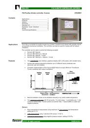
<strong>F37</strong> CLIMATE CONTROLLER<br />
Contents<br />
<strong>F37</strong> Poultry climate controller, 2 zones<br />
Applications _______________________ 1<br />
Features __________________________ 1<br />
Options ___________________________ 3<br />
Examples screens __________________ 3<br />
Examples house situations ___________ 4<br />
Standard I/O _______________________ 5<br />
Wiring ____________________________ 6<br />
Technical specifications ______________ 7<br />
A7020<strong>04</strong>1<br />
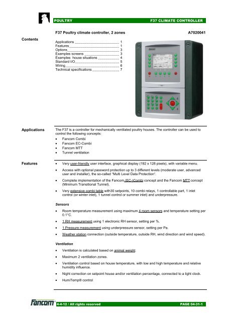
Applications<br />
The <strong>F37</strong> is a controller for mechanically ventilated poultry houses. The controller can be used to<br />
control the following concepts:<br />
• Fancom Combi<br />
• Fancom EC-Combi<br />
• Fancom <strong>MTT</strong><br />
• Tunnel ventilation<br />
Features • Very user-friendly user interface, graphical display (192 x 128 pixels), with variable menu.<br />
• Access with optional password protection up to 3 different levels (moderate user, advanced<br />
user and installer), the so-called “Multi Level Data Protection“.<br />
• Complete implementation of the Fancom (EC-)Combi concept and the Fancom <strong>MTT</strong> concept<br />
(Minimum Transitional Tunnel).<br />
• Very extensive combi table with30 setpoints, 10 combi relays, 1 controllable part, 1 inlet<br />
control (or winter inlet), 1 tunnel control or summer inlet) and underpressure.<br />
Sensors<br />
• Room temperature measurement using maximum 4 room sensors and temperature setting per<br />
0.1°C.<br />
• 1 RH measurement using 1 electronic RH sensor, setting per %.<br />
• 1 Pressure measurement using underpressure sensor, setting per Pa.<br />
• Weather station connection (outside temperature, outside RH, wind direction and wind speed).<br />
Ventilation<br />
• Ventilation is calculated based on animal weight.<br />
• Maximum 2 ventilation zones.<br />
• Ventilation control based on house temperature, with low and high temperature and relative<br />
humidity influence.<br />
• Night correction on setpoint house and/or ventilation percentage, connected to a light clock.<br />
• HumiTemp® control<br />
4-4-12 / All rights reserved PAGE <strong>04</strong>-<strong>31</strong>-1
POULTRY<br />
<strong>F37</strong> CLIMATE CONTROLLER<br />
Exhaust<br />
• Maximum 10 relays controlled, optionally combined with a linear fan control (Combi or EC-<br />
Combi).<br />
• Linear Fan control enables to control controllable fans (via triac, frequency controller, EC-fans,<br />
ITM) or modulating ON/OFF fans. Rotation (changing between fans) can be used with<br />
modulating fans.<br />
• Up to maximum 4 ITM’s can be controlled using the I/O network.<br />
• Separate vortex damper control, linked to linear exhaust using a settable factor.<br />
Inlet control<br />
• 2 Inlet controls (2 zones) to control inlets or valves using the same setting. The valves can<br />
mutually be corrected based on temperature difference.<br />
• 1 Tunnel inlet. Separate inlet control to control a tunnel shutter or curtain.<br />
Curve<br />
• The following settings can be programmed in a curve (maximum 20 setpoints):<br />
- Day number<br />
- House temperature<br />
- Extra temperature (e.g. for heating)<br />
- Desired RH<br />
- Animal weight<br />
- Minimum ventilation (in m 3 /kg/h)<br />
- Maximum ventilation (in % or a tunnel position)<br />
Heating / cooling / humidification<br />
• 3 Heating controls, ON/OFF, time modulating, analog, based on their own sensor and linked<br />
to:<br />
- the house temperature or<br />
- an extra temperature<br />
• 2 Cooling control, ON/OFF or time modulating, based on their own sensor and linked to:<br />
- the house temperature or<br />
- the house temperature + bandwidth or<br />
- an extra temperature or<br />
- the first tunnel position<br />
• 1 Humidification control, ON/OFF or time modulating based on relative humidity in the house.<br />
• Heat demand through F-Net; in combination with a central heating control (e.g. F21).<br />
• OptiSec® control<br />
Time clocks and registration<br />
• 1 Feed clock enabling to enter maximum 24 start and stop times for feeding. Feed<br />
consumption is registered for a settable time interval (Management & Monitoring ® ), of today,<br />
yesterday, day before yesterday and total. A pulsed weighing system or external weighing<br />
systems generating pulses (e.g. directly on an auger) can be used for registration. Feed flow<br />
(under- and overflow) alarm and maximum runtime alarm.<br />
• 1 Water clock enabling to enter maximum 24 start and stop times for water dosage. Water<br />
consumption is registered for a settable time interval (Management & Monitoring ® ), of today,<br />
yesterday, day before yesterday and total. A water meter can be used for the water<br />
registration. Water flow (leakage, under- and overflow) alarm.<br />
• 8 Light clocks enabling to enter maximum 24 start and stop times. Setting possibilities:<br />
increase/decrease times (dimmer functions), settable light intensity (with light meter) and<br />
connection to light curve.<br />
• 4 Time clock enabling to enter maximum 24 start and stop times. This time clock has several<br />
applications, but no registration functions.<br />
4-4-12 / All rights reserved PAGE <strong>04</strong>-<strong>31</strong>-2
POULTRY<br />
<strong>F37</strong> CLIMATE CONTROLLER<br />
• 32 Registration groups for feed, water or other purposes.<br />
Alarm<br />
• 8 External alarms (free programmable) and application alarms via 1 alarm relay.<br />
<br />
Temperature differential signalling for giving a signal to an external automatic fire alarm<br />
system (AFAS).<br />
Options A5<strong>04</strong>5011 Temperature sensor SF.7 for inside and outside temperatures<br />
A2220008.10 RHM.17 electronic inside RH meter + temperature sensor<br />
A4170007.01 0-100 Pa pressure sensor + 10 meter hose for underpressure measurement<br />
A5140012<br />
FLS (Fancom Light Sensor) electronic light sensor<br />
A5220016.10 RHO.17 electronic outside RH meter + temperature sensor<br />
A5220015<br />
A7018014<br />
A5190005<br />
A5261001<br />
A5261002<br />
A5030115<br />
A5030114<br />
A5030110<br />
A5030111<br />
Weather station Plus, vane + anemometer.<br />
IRM.16 relay station for extra relays<br />
AI.4 module with 4 extra analog inputs and pulsed input, e.g. for weather<br />
station connection or extra sensors for outside conditions.<br />
Water meter 3m 3 /h, ¾” + pulse<br />
Water meter 5m 3 /h, 1” + pulse<br />
Water valve ¾” NO 24 Vac<br />
Water valve ¾” NO 220 Vac<br />
Water valve 1” NO 24 Vac<br />
Water valve 1” NO 220 Vac<br />
Examples<br />
screens<br />
4-4-12 / All rights reserved PAGE <strong>04</strong>-<strong>31</strong>-3
POULTRY<br />
<strong>F37</strong> CLIMATE CONTROLLER<br />
Examples<br />
house situations<br />
Combi<br />
• Separate valves<br />
left and right<br />
Combi<br />
• Separate summer<br />
and winter valves<br />
Combi<br />
• Separate valves<br />
left and right and<br />
tunnel inlet<br />
Cross<br />
Separate valves<br />
in front and back<br />
Cross - Tunnel<br />
4-4-12 / All rights reserved PAGE <strong>04</strong>-<strong>31</strong>-4
POULTRY<br />
<strong>F37</strong> CLIMATE CONTROLLER<br />
Corner ventilation<br />
Tunnel ventilation<br />
Standard I/O<br />
THE NUMBER OF CONTROLS WHICH CAN BE USED IS LIMITED BY THE NUMBER OF<br />
AVAILABLE INPUTS AND OUTPUTS:<br />
IOB.4<br />
• 4 analog inputs for temperature sensors (inside, outside), RH sensors (inside, outside),<br />
underpressure sensor and wind direction<br />
• 4 relays, potential free<br />
• 1 alarm relay<br />
• 4 0-10V voltage outputs for control of controllable ventilation, inlet position, vortex damper<br />
and tunnel inlet or extra inlet.<br />
• 4 digital inputs for registration and wind speed<br />
FRM.8<br />
• 8 relays, potential free<br />
4-4-12 / All rights reserved PAGE <strong>04</strong>-<strong>31</strong>-5
POULTRY<br />
<strong>F37</strong> CLIMATE CONTROLLER<br />
Wiring<br />
Power<br />
3 x 2,5 mm 2 Humidification relay<br />
2 x 0,8 mm (0,5 mm 2 )<br />
3 x 0,8 mm (0,5 mm 2 )<br />
2 x 0,8 mm (0,5 mm 2 )<br />
2 x 0,8 mm (0,5 mm 2 )<br />
2 x 0,8 mm (0,5 mm 2 )<br />
4 x room temp. sensor<br />
RH sensor<br />
Voltage output (0-10V)<br />
2 x air inlet control<br />
Voltage output (0-10V)<br />
tunnel control<br />
Heating<br />
((3x) on/off)<br />
2 x 0,8 mm (0,5 mm 2 )<br />
2 x 0,8 mm (0,5 mm 2 )<br />
2 x 0,8 mm (0,5 mm 2 )<br />
2 x 0,8 mm (0,5 mm 2 )<br />
Cooling relay<br />
10 * ventilation group<br />
Alarm<br />
2 x 0,8 mm (0,5 mm 2 )<br />
3 x 0,8 mm (0,5 mm 2 )<br />
2 x 0,8 mm (0,5 mm 2 )<br />
2 x 0,8 mm (0,5 mm 2 )<br />
FNet*<br />
**<br />
Outside temperature<br />
Outside RH sensor<br />
Wind direction<br />
Wind velocity<br />
Network communication<br />
* Greenlink: 2 x 0,8 mm 2 twisted pair<br />
** Maximum 30 F-net modules in 1 network<br />
4-4-12 / All rights reserved PAGE <strong>04</strong>-<strong>31</strong>-6
POULTRY<br />
<strong>F37</strong> CLIMATE CONTROLLER<br />
Technical<br />
specifications<br />
4-4-12 / All rights reserved PAGE <strong>04</strong>-<strong>31</strong>-7


![12-21 Dakkokersysteem 63-80 [GB] - Farmi Tilatech Oy](https://img.yumpu.com/37523556/1/184x260/12-21-dakkokersysteem-63-80-gb-farmi-tilatech-oy.jpg?quality=85)