TELECOMMUNICATIONS TEST EQUIPMENT - Promax
TELECOMMUNICATIONS TEST EQUIPMENT - Promax
TELECOMMUNICATIONS TEST EQUIPMENT - Promax

Create successful ePaper yourself
Turn your PDF publications into a flip-book with our unique Google optimized e-Paper software.
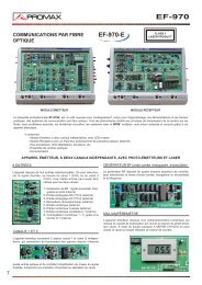
<strong>TELECOMMUNICATIONS</strong> <strong>TEST</strong><br />
<strong>EQUIPMENT</strong>
CHOOSE THE IDEAL <strong>EQUIPMENT</strong><br />
TERRESTRIAL<br />
SATELLITE<br />
CABLE<br />
TV MONITOR<br />
SPECTRUM ANALYZER<br />
DIRECT READ OUT<br />
CARRIER NOISE<br />
CHANNEL POWER<br />
DIGITAL CARRIER NOISE<br />
BIT ERROR RATIO<br />
DCI (DVB CHANNEL IDENTIFIER)<br />
MPEG DEMODULATION<br />
DATA LOGGER<br />
PAGE<br />
PROLINK-7 (*)<br />
MPEG<br />
7<br />
PROLINK-3 (*)<br />
PROLINK-1B (*)<br />
PROMAX-8+<br />
PROMAX-6<br />
PROMAX-5<br />
PROMAX-4<br />
PRODIG-2<br />
MC-377<br />
MC-360B<br />
MC-160B<br />
MS-250<br />
Optical measuring instruments, Pilot Generator, Network channel, Accessories<br />
DVB<br />
1<br />
19<br />
13<br />
17<br />
17<br />
17<br />
21<br />
11<br />
10<br />
10<br />
10<br />
(*) Maximum configuration<br />
TERRESTRIAL<br />
SATELLITE CABLE CABLE<br />
MARKING<br />
SUB-BAND<br />
ESPETRUM<br />
SPECTRUM<br />
REAL TIME<br />
READ OUT<br />
CARRIER<br />
NOISE<br />
AVERAGE<br />
POWER<br />
INTEGRATION<br />
POWER<br />
DIGITAL<br />
CARRIER NOISE<br />
BER<br />
DVB<br />
MPEG<br />
DVB CHANNEL<br />
IDENTIFIER<br />
MPEG<br />
DEMODULATIOIN<br />
DATA<br />
LOGGER<br />
B/W<br />
TV MONITOR<br />
COLOUR<br />
TV MONITOR
TV & SATELLITE ANALYSER<br />
PROLINK-3<br />
The PROLINK-3 is a range of<br />
analysers designed for installation<br />
and maintenance of television and<br />
data systems in terrestrial, cable and<br />
satellite transmissions<br />
It incorporates direct measurements<br />
for the evaluation of radio,<br />
television and data signal quality.<br />
It also measures analogue signals<br />
from any TV standard to be<br />
demodulated and identification of<br />
digital signals.<br />
PROLINK-3<br />
PROLINK-3+<br />
PROLINK-3C+<br />
PROLINK-3S<br />
AN INSTRUMENT FOR EVERY APPLICATION<br />
Satellite Terrestre Sub-Band Teletext DiSEqC Colour<br />
TXT DiSEqC<br />
It is portable, it is rugged and easy<br />
to use. In order to make readings<br />
easy all measurement results are<br />
shown on the screen. It includes a<br />
powerful data acquisition system<br />
(DATA LOGGER) with capacity to<br />
evaluate automatically up to 99<br />
channels.<br />
Two options are provided for<br />
measuring digital signals: the Bit<br />
Error Ratio (BER) and DVB channel<br />
identifier (DCI) which enables<br />
the operator and/or program to be<br />
identified.<br />
PROLINK-3<br />
PROLINK-3+<br />
PROLINK-3C+<br />
PROLINK-3S<br />
OPT-103-81<br />
QPSK-SAT<br />
AVAILABLE OPTIONS<br />
OPT-103-82<br />
QAM-CATV<br />
OPT-103-83<br />
COFDM-DTT<br />
OPT-103-85<br />
QPSK/QAM<br />
OPT-103-86<br />
QPSK/COFDM<br />
OPT-103-11 long-life batteries option<br />
Trade Mark of the DVB Digital Video Broadcasting Project (1830 to 1832)<br />
1
PROLINK-3<br />
The PROLINK-3 instruments include functions for<br />
signal quality evaluation. For analogue signals these<br />
measurements are: Level, Video / Audio and Carrier<br />
/ Noise. In the case of digital signals: Channel<br />
Power, Carrier / Noise and option Bit Error Ratio<br />
consideration the spectral distribution of the<br />
signal. The first method has the advantage of<br />
being very quick. The second determines signal<br />
power with greater precision, especially for<br />
degraded digital signals.<br />
Carrier<br />
Reference<br />
noise<br />
Measuring Carrier/Noise (C/N)<br />
Measuring the C/N ratio is essential to be able to<br />
certify the immunity of a TV installation against<br />
noise, whether analogue or digital. With the<br />
PROLINK-3 the user can perform this measurement<br />
either in AUTO or REFERENCED mode.<br />
In AUTO mode, the PROLINK-3 automatically<br />
defines the frequency to measure the noise.<br />
and DVB channel identifier (DCI)<br />
Digital channel power<br />
The CHANNEL POWER of a digital signal can<br />
be calculated by averaging out or by taking into<br />
Bit Error Ratio measurement (BER)<br />
The Bit Error Ratio (BER) is the measurement that<br />
actually evaluates the quality of a digital signal and<br />
determines whether it is enough to be reproduced by<br />
the receiver or not. The selectable options are:<br />
OPT-103-81 QPSK Measurement<br />
In REFERENCED mode, it is the user who<br />
defines the frequency where the noise level is to<br />
be measured.<br />
This mode is particularly useful for calculating the<br />
Carrier/Noise ratio in environments with a high<br />
density of analogue and digital channels.<br />
2
DIGITAL & ANALOGUE TV<br />
This option permits BER to be measured before<br />
and after Viterbi as well as the total number of<br />
wrong packets (WP) within a period of time.<br />
Furthermore, it identifies DVB (DCI) signals in<br />
MCPC & SCPC Satellite transmissions.<br />
Measuring the error ratio before the first correction<br />
(Viterbi) is more sensitive to small variations<br />
in the quality of reception. Measuring after<br />
Viterbi enables the measurement to conform to the<br />
quality minimums laid down by DVB, which are<br />
determined by a threshold (QEF).<br />
OPT-103-82 QAM Measuring<br />
This option permits the measurement of BER and<br />
the total number of wrong packets (WP) in a<br />
period of time. It also identifies DVB (DCI)<br />
signals in Cable TV transmissions.<br />
OPT-103-83 COFDM Measuring<br />
This option permits the measurement of BER after<br />
Viterbi, the total number of Wrong Packets (WP),<br />
and the identification of DVB (DCI) signals for<br />
DVB-Terrestrial signals.<br />
CSI (Channel Status Information) provides<br />
additional information on the quality of the carriers<br />
forming a COFDM channel. Its value should always<br />
be the lowest possible.<br />
Another function that this option allows is the<br />
measurement of the number of reception breaks, the<br />
period of each one of these breaks and the total time<br />
without reception.<br />
DVB Channel identifier (DCI)<br />
When it comes to determining the quality with<br />
which a digital signal is being received, there is no<br />
doubt that the Bit Error Ratio (BER) is a<br />
fundamental parameter.<br />
To correctly measure the error ratio we need to<br />
demodulate the digital channel. This complex<br />
process is performed by the PROLINK-3. First the<br />
digital channel is tuned and demodulated in radio<br />
frequency using a QPSK, QAM or COFDM<br />
demodulator depending on the case in hand. This<br />
process gives us a digital signal which could be<br />
called base band and which in effect is composed<br />
of a sequence of bytes known as the “Transport<br />
Stream”.<br />
The “Transport Stream” can be in parallel (words<br />
of 8 bits) or in a series sequence, and is composed<br />
of conveniently labelled information packets of<br />
188 bytes each. In DVB systems the packets<br />
contain video, audio or data information. The data<br />
packets can in turn be grouped together<br />
constituting tables, some of these contain<br />
information which the network operator can edit<br />
in the transmission centre and indicate the type of<br />
service being offered to users.<br />
Some of these tables are of special interest,<br />
NETWORK Identification Table, BOUQUET<br />
Association Table, and SERVICE Description<br />
Table.<br />
The different error ratio measuring options of the<br />
PROLINK-3 includes the DCI function (DVB<br />
Channel Identifier).<br />
The DCI studies the “Transport Stream”, determines<br />
whether it is DVB or not, to then demodulate<br />
and analyse the information in the NETWORK,<br />
BOUQUET and SERVICE Tables. It then displays<br />
it repeatedly on the BER measuring screen.<br />
The DCI function, patented by PROMAX, allows<br />
to know which channel has been tuned and to<br />
measure it totally automatically. Until now, this<br />
was only possible with an MPEG-2 decoder.<br />
On selecting the measurement of a digital signal,<br />
the cursors automatically place themselves to<br />
measure channel power at both ends of the signal,<br />
depending on the selected BW (8 MHz in the<br />
example).<br />
Battery<br />
One of the main elements of an instrument of<br />
these characteristics is the battery. Not only the<br />
equipment must have own internal source but also<br />
its duration must be enough for a continued use.<br />
Option OPT-103-11 is a long life battery pack,<br />
which extends the equipment autonomy to over 3<br />
hours. This option can be provided with the equipment<br />
or it can adapted later.<br />
The equipment has a function to verify the battery<br />
state at any time.<br />
Also it allows measuring the external units current<br />
and voltage supply. The Low Bat. indication in<br />
the lower side of the horizontal bar indicates the<br />
low battery level starting from which it is<br />
advisable to charge the battery. In the lower side<br />
of the screen it appears the external units voltage<br />
supply and the supplied current (I LNB, 200 mA<br />
in the example).<br />
Your comfort our priority<br />
Weighting just 4,9 kg battery included and being<br />
so compact, the PROLINK-3 is the only one capable<br />
to offer such revolutionary functions in such a<br />
small instrument.<br />
OPT-103-85 QAM &QPSK Measurement<br />
Includes options OPT-103-81 and OPT-103-82<br />
OPT-103-86 COFDM& QPSK Measurement<br />
Includes options OPT-103-81 and OPT-103-83<br />
Bit Error Ratio for SCPC<br />
The Bit Error Ratio of QPSK signals allows measurements<br />
on MCPC multiplexed channels<br />
(Multiple Channels Per Carrier) as well as SCPC<br />
channels (Single Channel Per Carrier).<br />
3
MORE THAN A SPECTRUM ANALYSER<br />
Fast, accurate and simple Spectrum Analyser<br />
As a spectrum analyser the PROLINK-3 has been optimised for measurements in television systems. The<br />
instrument allows selection of Frequency Range (Span), Reference Level and Sweep Time. These parameters<br />
can be adapted for an optimum signal representation in accordance with the type of measurement to be<br />
done. For example, when using the equipment to<br />
align an antenna, it is very useful to select the<br />
Sweep Time as Fast or directly choose the Antenna<br />
Alignment function in order that the display follows<br />
closely every change in the behaviour of the signal.<br />
On the other hand, if the representation must show<br />
signal evolution accurately, for example in a Cable<br />
TV system, it will be more appropriate to select the<br />
Accurate sweep mode.<br />
To keep the operation simple the instrument automatically<br />
presets certain configurations depending<br />
upon measurement mode selected.<br />
Rough use protection<br />
Rugged construction has been one of the most important<br />
issues taken into account in the PROLINK-3<br />
design. Despite its low weight the chassis and casing<br />
are metallic for improved shock protection.<br />
A rubber shock protector and a special mechanism<br />
to fix the monitor reduces the effects of accidental<br />
drop. The input and output connectors are located<br />
on a side of the instrument and the only control<br />
knob, which is located on the front panel is protected<br />
against ingress of dust and water<br />
In all environments<br />
Every detail has been taken into account to ensure<br />
the instrument is ideal for operation in any environment.<br />
When DUAL MARKER mode is selected two markers appear on the screen with indication of level and<br />
frequency difference between them. With 50 dB dynamic range, frequency or channel and level indication<br />
simultaneously on the screen the interpretation of the readings is immediate.<br />
At any time it is possible to obtain a printed copy of the spectrum display.<br />
The carrying bag itself has an incorporated<br />
viewing hood to improve monitor contrast when<br />
operated in direct sun light.<br />
On selecting the measurement of a digital signal, the cursors automatically place themselves to measure<br />
channel power at both ends of the channel, according to the selected BW (8 MHz in the example).<br />
4
PROLINK-3<br />
Acquisition and data processing<br />
The PROLINK-3 can be used as a data acquisition<br />
system. It can analyse up to 99 channels at one<br />
particular outlet with just a command. It can make<br />
many kinds of measurements including Bit Error<br />
Ratio. The process can be repeated for up to 99<br />
outlets since the capacity of the system is 9,801<br />
measurements.<br />
It is also possible to repeat measurements over<br />
time. In this mode the instrument will take sets of<br />
measurements every given time interval. This<br />
function can be very useful for permanent<br />
monitoring of signals or intermittent faults<br />
location. With the help of the RM-103 software<br />
package all data can be downloaded to a computer<br />
to be analysed with more detail.<br />
An instrument for every application<br />
To choose the right PROLINK-3 for your<br />
application you should refer to the table previously<br />
showing. Following is a brief description of what<br />
function can be configured in the different versions.<br />
There is a PROLINK-3S covering just the satellite<br />
TV band. The remaining versions offer both<br />
terrestrial<br />
and satellite TV bands. Any of the available Bit<br />
Error Ratio options can be added to the selected<br />
PROLINK-3 version as shown in the table as well.<br />
Return-path<br />
The variants that include this function cover the<br />
frequency range used in the Cable TV return path.<br />
This frequency range runs typically from 5 to<br />
50 MHz.<br />
The results can<br />
be stored in the<br />
memory or also<br />
transferred to a<br />
printer to obtain<br />
reports just in<br />
the place where<br />
the measurements<br />
are made.<br />
For this purpose<br />
the CI-023 printer<br />
can be<br />
attached to the<br />
instrument's<br />
carrying bag.<br />
It is possible to print both data lists and the spectrum<br />
display.<br />
Easy to use<br />
Easy of use was a priority during design of the<br />
instrument. Direct access keys and a single<br />
selection command allow an inmediate selection<br />
of the desired function.<br />
An iconographic menu easies the identification of<br />
all functions.<br />
The selection of all the functions is made by<br />
means of an just one rotary selector.<br />
Various types of reports,<br />
graphics or statistics can<br />
be generated using a<br />
standard spread sheet or<br />
any other data processing<br />
software.<br />
Back-pack type carrying case<br />
The equipment is delivered with a carrying bag<br />
that can be used as a backpack. Making it easier to<br />
climb ladders and other difficult locations.<br />
Teletext<br />
The teletext is a text information contained inside<br />
the analogue television signal itself. It happens to<br />
be a digital signal with high sensitivity to noise<br />
and that's why it becomes one of the most crucial<br />
parameters to be checked in an analogue installation.<br />
DiSEqC 1.2<br />
DiSEqC 1.2 compatible devices such us LNBs,<br />
switches, positioners, etc. can be controlled by<br />
means of this function.<br />
The desired installation configuration will be<br />
determined via a program made of a set of simple<br />
instructions. This program can contain up to 99 of<br />
the instructions and can be saved in memory to be<br />
used at a later stage.<br />
Black & white or colour screen<br />
The screen type desired can be also selected<br />
between Black & White CRT or Colour LCD, TFT.<br />
5
PROLINK-3<br />
SPECIFICATIONS<br />
SPECIFICATIONS<br />
PROLINK-3<br />
TUNING<br />
Digital frequency synthesis. Continuous<br />
tuning from 5 to 862 MHz and from 920 to<br />
2150 MHz<br />
Tuning modesFrequency, Channel or Memory.<br />
Channel plan configurable on demand<br />
Resolution<br />
50 kHz<br />
Automatic search<br />
Threshold level selectable<br />
Memory<br />
99 positions for measurement configurations<br />
RF Input<br />
Impedance<br />
Connector<br />
Maximum signal<br />
Maximum input voltage<br />
DC to 100 Hz<br />
5 MHz to 2150 MHz 130 dBµV<br />
75 W<br />
BNC, F or TV by adapter<br />
130 dBµV<br />
50 V rms (powered by the AL-103 power adapter)<br />
30 V rms (not powered by the AL-103 power<br />
adapter)<br />
Level measurement<br />
Measurement range<br />
Terrestrial TV & FM bands 20 dBµV to 130 dBµV (10 µV to 3.16 V)<br />
Satellite TV band 30 dBµV to 120 dBµV (31.6 µV to 1 V)<br />
Reading<br />
Auto-range, reading is displayed on a (OSD)<br />
Digital<br />
Absolute value calibrated in dBµV, dBmV or<br />
dBm<br />
Analogue<br />
Relative value through an analogue bar on the<br />
screen<br />
Measurement bandwidth 230 kHz (Terrestrial band) 4 MHz (Satellite<br />
band) (maximum band ripple 1 dB).<br />
Audible indicator<br />
LV audio. A tone with pitch proportional to<br />
signal strength.<br />
Accuracy (typical)<br />
Sub-band<br />
± 2.5 dB (50-120 dBµV, 5-45 MHz) (22ºC ± 5ºC)<br />
Terrestrial bands ± 1.5 dB (30-120 dBµV, 48,25-861 MHz)<br />
(22ºC ± 5ºC)<br />
Satellite band<br />
± 1.5 dB (40-100 dBµV, 920-2050 MHz)<br />
(22ºC ± 5ºC)<br />
Out of range indication (over), ¯ (under)<br />
Measurements in TV modes<br />
Terrestrial bands<br />
Analogue channelsLevel, Video-Audio ratio and Carrier/Noise<br />
ratio (Auto and Referenced)<br />
Digital channelsChannel power (Auto) and Carrier/Noise ratio<br />
(Auto and Referenced).<br />
Satellite band<br />
Analogue channelsLevel and Carrier/Noise ratio (Auto and<br />
Referenced )<br />
Digital channelsChannel power (Auto) and Carrier/Noise ratio<br />
(Auto and Referenced).<br />
DATA LOGGER function Automatic acquisition of up to 9801 measurements<br />
Spectrum analyser mode<br />
Satellite band 30 dBµV to 120 dBµV (31.6 µV to 1 V)<br />
Terrestrial bands 20 dBµV to 130 dBµV (10 µV to 3.16 V)<br />
Measurement bandwidth<br />
Terrestrial<br />
230 kHz, 1 MHz selectable<br />
Satellite<br />
230 kHz, 4 MHz selectable<br />
Span<br />
Terrestrial Full span (full band), 500, 200, 100, 50, 32,<br />
16, 8 MHz selectable.<br />
Satellite Full span (full band), 500, 200, 100, 50, 32<br />
MHz selectable.<br />
Markers2 with level, frequency, level difference and<br />
frequency difference indications.<br />
Measurements<br />
Terrestrial bands<br />
Analogue channelsLevel and Carrier-Noise ratio (Referenced)<br />
Digital channelsChannel power (Integration method) and<br />
Carrier-Noise ratio (Referenced).<br />
Satellite band<br />
Analogue channelsLevel and Carrier-Noise ratio (Referenced)<br />
Digital channelsChannel power (Integration method) and<br />
Carrier-Noise ratio (Referenced).<br />
Monitor Display<br />
Monitor<br />
Colour system<br />
TV standard<br />
Synchronism and Burst<br />
Spectrum mode<br />
Sensitivity<br />
Synchronism 50/60 Hz<br />
B & W 4 ½ inches<br />
PAL, SECAM and NTSC<br />
M, N, B, G, I, D, K and L<br />
Graphic representation over the picture<br />
Variable span and reference level<br />
40 dBµV for correct synchronism<br />
Automatic selection according to the system<br />
Video Signal<br />
External video input Scart (automatic)<br />
Sensitivity<br />
1 Vpp (75 W ) positive video<br />
Video output Scart (75 W)<br />
Sound<br />
Input<br />
Scart<br />
OutputsBuilt in speaker, Scart<br />
Demodulation<br />
AM, FM and TV, selectable<br />
De-emphasis 50 µs<br />
Subcarrier<br />
Digital frequency synthesis<br />
Variable<br />
From 4 to 9 MHz, 10 kHz resolution<br />
Fixed<br />
Terrestrial According to the active standard: 4.50 - 5.50 -<br />
5.80 -6.00 - 6.50 - 6.65 - 5.74 - AM - FM - LV - OFF.<br />
Satellite<br />
6.65 - 5.80 - 6.50 - 7.02 - LV - OFF<br />
Teletext<br />
RS-232C Interface<br />
Decodes at 1.5 level<br />
External unit power<br />
SUPPLY<br />
Through the RF input connector<br />
Terrestrial<br />
External or 13/15/18 V<br />
Satellite<br />
External or 13/15/18 V<br />
22 kHz signal Selectable<br />
Voltage<br />
0.6 V ± 0.2 V<br />
Frequency<br />
22 kHz ± 4 kHz<br />
Maximum power<br />
5 W<br />
DiSEqC Generator<br />
According to DiSEqC 1.2 standard<br />
Power Supply<br />
Internal<br />
Batteries2 x 6 V 3.3 Ah lead acid batteries<br />
Autonomy<br />
> 1 hour non stop<br />
Recharging time 12 h starting from a complete discharge<br />
External<br />
Voltage<br />
12 V<br />
Consumption<br />
Auto power off<br />
Operating environmental<br />
conditions<br />
Altitude<br />
Temperature range<br />
Max. relative humidity<br />
Mechanical features<br />
Dimensions<br />
Weight<br />
42 W<br />
After 15 minutes without operating on any<br />
control. Can be desabled.<br />
Up to 2000 m<br />
From 5 to 40 º C<br />
80 % (up to 31ºC), decreasing lineally up to<br />
50% at 40º C.<br />
280 (W) x 95 (H) x 250 (D) mm<br />
4.9 kg<br />
6
PROLINK-7<br />
TV & SATELLITE ANALYSER<br />
The PROLINK-7 is a revolutionary signal analyser, designed for the installation and maintenance of television and data systems.<br />
Its functions have been designed to achieve optimum performance in the reception and distribution of terrestrial, cable TV and satellite TV, microwave networks<br />
(MMDS)and radio signals.<br />
It enables the user to analyse the quality of both analogue and digital TV transmissions. The features also meet the strict technical requirements needed to install<br />
VSAT (Very Small Aperture Terminals) systems.<br />
Its frequency range covers from 5 MHz up to 2150 MHz. Therefore, it is suitable for taking measurements in the return path in cable TV applications as well as<br />
in the satellite IF band.<br />
All functions can be accessed by a single selector located on the front panel and associated menus which allow for a quick and intuitive instrument operation.<br />
Types of measurements Analogue-Digital<br />
It accepts any analogue TV standard and any TV<br />
system. Signal measurements can be made within<br />
the satellite IF band, with positive or negative video<br />
modulation. It allows the following measurements:<br />
Level, Video to Audio ratio and Carrier to Noise<br />
ratio. The display of the sync pulse signal and the<br />
teletext are extremely useful to achieve optimum<br />
performance for analogue TV signals.<br />
For digital signals it provides the channel Power and<br />
also the Bit Error Ratio (BER), the last by means of<br />
the appropriate option.<br />
The graphic bar representation and the acoustic<br />
level tone are ideal for the maximum signal adjustment.<br />
It also provides an audio demodulator.<br />
Spectrum mode. Variable resolution.<br />
The equipment includes a spectrum analysis<br />
function, which permits to identify any signal in<br />
real time with the maximum easy. It has different<br />
resolution filters: 1 MHz (only terrestrial bands)<br />
4 MHz (only satellite band), 230 kHz and 100<br />
kHz, which can be selected for an optimum use<br />
in any type of application. In this way, for example,<br />
the 4 MHz filter will be the most suitable for<br />
satellite dish alignment and for optimum<br />
adjustment of the cross polarisation. With this<br />
filter one can perfectly distinguish a digital<br />
channel from an analogue one. In the other<br />
applications such us VSAT selecting a narrow<br />
filter will be more useful.<br />
Memories and Data Acquisition<br />
The instrument can store up to 99 different configurations,<br />
with settings of frequency or channel,<br />
the name of the broadcasting station, measurement<br />
units, measurement type, etc.<br />
By using the Data Logger, the equipment is converted<br />
into a powerful data adquisition systemwith<br />
a memory of 9801 parameters. This permits<br />
the user to carry out up to 99 measuring sessions<br />
on a maximum of 99 channels. Measurements<br />
can be done automatically and in predetermined<br />
time periods. All functions can be remote controlled<br />
by use of RM-007.<br />
7
PROLINK-7<br />
SPECIFICATIONS<br />
SPECIFICATIONS<br />
Tuning<br />
PROLINK-7<br />
Digital frequency synthesis.<br />
from 5 to 862 MHz an from 920 a 2150<br />
Spectrum bands<br />
Sub-band Sub-band 5 - 45 MHz<br />
VHF LOW band 45 - 170 MHz<br />
HIGH band 170 - 450 MHz<br />
UHF UHF band 450 - 862 MHz<br />
SAT SAT TV 1 st IF 920 - 2150 MHz<br />
FM FM band 87 - 109 MHz<br />
IF input<br />
38.9 MHz<br />
Tuning modesFrecuency, Channel or memory. On demand<br />
channel table<br />
Display<br />
LCD 16x2 alphanumeric<br />
Resolution<br />
62.5 kHz in TV and FM<br />
500 kHz in SAT<br />
Automatic Search<br />
Selectable threshold<br />
Memory<br />
99 configurations<br />
Data Logger<br />
9081 measurements<br />
Level Measurement<br />
Measurement Range<br />
Terrestrial TV & FM bands 20 dBmV to 130 dBmV (10 mV to 3.16 V)<br />
Satellite TV Band 30 dBmV to 120 dBmV (31.6 mV to 1V)<br />
Spectrum Mode<br />
Terrestrial bands 20 dBmV to 130 dBmV (10 mV to 3.16 V)<br />
Satellite band 30 dBmV to 120 dBmV (31.6 mV to 1 V)<br />
Reading<br />
Auto-range or manual selection<br />
Digital<br />
Absolute value calibrated in dBmV, dBmV,<br />
dBm or V<br />
Analogue<br />
Relative value, analogue bar on the<br />
screen<br />
Attenuators<br />
Terrestrial bands 0 to 80 dB, AUTO (10 dB steps)<br />
Satellite band<br />
0 to 60 dB, AUTO (10 dB steps)<br />
Input impedance<br />
75W (BNC)<br />
Measurement bandwidth 230 kHz (Terrestrial bands) or 4 MHz (Sat<br />
band) (maximum band ripple 1 dB).<br />
Acustic indicator<br />
A tone varies with the signal level<br />
Accuracy<br />
Terrestrial bands ± 1 dB (30 dBmV to 120 dBmV and 46<br />
to 862 MHz) (22ºC ± 5ºC)<br />
Satellite band<br />
± 1 dB (40 dBmV to 100 dBmV) (22ºC ± 5ºC)<br />
RF output<br />
75W (BNC)<br />
Insertion losses<br />
22 dB typical, with 10 dB RF input attenuator<br />
Maximum signal<br />
RF input<br />
DC to 30 MHz<br />
50 V rms<br />
45 to 2150 MHz 130 dBmV<br />
Video input<br />
3 Vpp<br />
Monitor<br />
TRC Black & White, 5"<br />
OSD Function<br />
Synchronism and Burst Display through displacement of the picture<br />
Spectrum function<br />
Full span<br />
Variable span<br />
Type of Monitor<br />
Bandwidth 4 MHz<br />
Selectable 100 kHz, 230 kHz, 4 MHz<br />
B/W TV according to the standards<br />
M,N,B,G,I,D,K,L<br />
Sensitivity<br />
40 dBmV for the correct sincronism<br />
50/60 Hz Synchronism<br />
Satellite band<br />
Selection of frame frequency between 50 and<br />
60 Hz<br />
Terrestrial bands Selection according to the standard<br />
Video signal<br />
Sensitivity<br />
Video output<br />
Base band SAT video output<br />
IF output BNC (75W )<br />
External video input BNC, Euroconnector<br />
1 Vpp (75W) (automatic selection) positive video<br />
BNC, Euroconnector (75W)<br />
BNC, 1 Vpp (75W)<br />
Sound<br />
Input<br />
Euroconnector<br />
OutputsSpeaker, Euroconnector, external headphone<br />
Demodulation<br />
AM, FM, NICAM and TV, selectable<br />
De-emphasis<br />
50 ms<br />
Subcarrier<br />
Digital frequency Synthesis<br />
Variable<br />
From 4 to 9 MHz, 10 kHz resolution<br />
Fixed According to the standard selected: 4.50, 5.0,<br />
5.80, 6.00, 6.50, 6.65, 5.74, AM, FM,LV,OFF<br />
.<br />
Teletext<br />
Decodes at 1.5 level<br />
Interface<br />
RS-232C<br />
Power to LNB<br />
Through the input RF connector<br />
Terrestrial TV<br />
External or 13/15/18/24 V (400 mA)<br />
Satellite TV<br />
External or 13/15/18 V (400 mA)<br />
22 kHz Selectable<br />
Voltage 0.6 V ± 0.2<br />
Frequency<br />
22 kHz ± 4 kHz<br />
Power supply<br />
Battery<br />
12 V / 6 Ah<br />
Autonomy<br />
Better than 1 h with external supply<br />
Better than 2 h without external supply<br />
Mains100 to 250 V AC/ 50-60 Hz<br />
Consumption<br />
65 W<br />
Operating environmental<br />
conditions<br />
Max. altitude<br />
Temperature range<br />
Max. relative humidity<br />
Mechanical features<br />
Dimensions<br />
Weight<br />
2000 m<br />
From 5 a 40º C<br />
80 % (up to 31ºC), decreasing linealy up to<br />
10% at 40 ºC.<br />
W.305 x H.145 x D. 334 mm<br />
11 kg<br />
8
DIGITAL TV MEASUREMENT OPTIONS<br />
OPT-107-19<br />
PROLINK-7 Rack Mounting<br />
The OPT-107-19 option provides the PROLINK-7<br />
in rack format. This is an excellent alternative<br />
when the instrument has to be used in modular<br />
systems. Because of the DATA LOGGER function,<br />
the instrument is well suited for continuous<br />
control applications in reception and signal distribution<br />
centres.<br />
OPT-107-21<br />
PROLINK-7 VSAT Antenna alignement<br />
The PROLINK-7 was introduced in 1996 with the idea to offer a modular instrument that could be<br />
compatible with the new digital standards that started to show up at that time. Since then we have<br />
introduced new options to adapt the equipment to the different new digital standards. To the different<br />
options for the measurement of QPSK, QAM and COFDM modulated signals, we have added options that<br />
combination of options and that includes even MPEG demodulation.<br />
These options can be provided with the equipment or can be incorporated later.<br />
This flexibility is based in the IMI system (Intelligent Module Interconnection) which also makes easy the<br />
update of the equipment control program in order to be able to incorporate versions later to the production<br />
version. This support guarantees the maximum profitability to present investment.<br />
VSAT system installations require a very fine<br />
adjustment in antenna orientation.<br />
The OPT-107-21 option is very useful in this case,<br />
as it enables the optimum adjustment of both<br />
antenna and LNB..<br />
OPT-107-71<br />
QPSK measurement of DVB-S signals<br />
OPT-107-72<br />
QAM measurement of DVB-C signals<br />
OPT-107-73<br />
COFDM measuring of DVB-T signals<br />
Enables the quality of digital DVB-S satellite<br />
signals to be measured.<br />
Includes BER measurement before and after<br />
Viterbi as well as the total number of Wrong<br />
Packets (WP) in a period of time.<br />
OPT-107-75<br />
QPSK & QAM measurement of PROLINK-7<br />
OPT-107-76<br />
QPSK & COFDM measurement of PROLINK-7<br />
Enables the quality of Digital Cable or DVB-C<br />
distribution signals to be measured. Includes<br />
measurement of BER and total number of wrong<br />
packets (WP) in a period of time. QEF enables the<br />
measurements to conform to the quality minimums<br />
laid down by DVB<br />
OPT-107-77<br />
Measurement and Demodulator QPSK + QAM.<br />
MPEG-2 Decoder<br />
Enables the quality of Terrestrial Digital DVB-T<br />
signals to be measured. Includes BER after<br />
Viterbi, and the total number of Wrong Packets<br />
(WP). CSI provides additional information on the<br />
quality of the carriers which form a COFDM<br />
channel<br />
OPT-107-78B<br />
Measurement and Demodulator QPSK + COFDM<br />
(2 k and 8 k). MPEG-2 Decoder<br />
9
TV & SATELLITE LEVEL METERS<br />
MC-360B MC-160B MS-250<br />
SPECIFICATIONS MC-360B MC-160B MS-250<br />
Tunning<br />
Frequency range<br />
Terrestrial From 46 to 856 MHz From 46 to 856 MHz in 4 bands From 950 to 2050 MHz<br />
Satellite (SAT TV 1 st IF)<br />
From 950 to 2050 MHz<br />
Frequency indication Digital frequency meter, 5 digits LCD Digital frequency meter, 4 digits LCD<br />
Resolution 100 kHz 100 kHz<br />
AFC<br />
In all bandsIn all bands<br />
Level measurement<br />
Input impedance 75 W (BNC) 75 W (BNC) 75 W ("F")<br />
Max input signal.<br />
TV 130 dBµV 130 dBµV<br />
SAT<br />
100 dBµV<br />
Measuring range<br />
TV 20 dBµV to 110 dBmV 20 dBµV-110 dBmV<br />
SAT From 50 to 100 dBmV From -30 to 5 dBmV<br />
Reading<br />
Analog Scale in dBµV(see options) Scale in dBµV (see options) and µV Level indicator<br />
Scale range 30 dB 30 dB<br />
Attenuators<br />
TV 20 dB (IF), 40 dB (RF) 20 dB (IF), 40 dB (RF), 20 dB steps<br />
SAT<br />
20 dB (RF)<br />
IF bandwidth<br />
TV 300 kHz 300 kHz<br />
SAT<br />
27 MHz<br />
Total accuracy (22ºC ±5)<br />
TV ± 2 dB ± 2,7 dB<br />
SAT<br />
± 2 dB (0.95 - 2.05 GHz) (0 dB atten.)<br />
+2/-4 dB (0.95 - 2.05 GHz) (20 dB atten.)<br />
Audible indicator Audible tone varies with the signal level Audible tone varies with the signal level Audible tone varies with the signal level<br />
Sound<br />
TV band demodulation AM/FM AM/FM<br />
Output power 0.25 W 0.25 W<br />
Loudspeaker Built-in Built-in<br />
Power to LNB SAT<br />
From the unit 12, 15, 18 V selectable/350 mA max External, through RF line<br />
From receiver 400 mA maximum Measure range 12 to 21 V<br />
Output to indoor unit<br />
Impedance<br />
Signal level<br />
75 W (BNC)<br />
-10 dB (approx.)<br />
Power supply<br />
Internal<br />
6x 1.5 V R14 batteries6 x 1.5 V R14 batteries<br />
Autonomy at 30% ON / OFF 5 h (SAT/TV) / 2 h (SAT+LNB) 17 h (alkaline) / 5 h (NiCd)<br />
External 12 to 15 VDC 12 to 15 VDC (power adaptor not included<br />
AL-11, 198 to 253 V AC or<br />
AL-11, 198 to 253 V AC or<br />
AL-21, 104 to 132 V AC<br />
AL-21, 104 to 132 V AC<br />
Internal charger 180 mA regulator for 15 h charge 180 mA regulator for 15 h charge<br />
Mechanical features<br />
Dimensions W. 197 x H. 87 x D. 190 mm W. 197 x H.87 x D. 138 mm W. 82 x H. 64 x D. 39 mm<br />
Weight 2.6 kg 1.9 kg 150 g<br />
10
MC-377<br />
TV & SATELLITE LEVEL METER<br />
SPECTRUM ANALYSER MONITOR LEVEL MEASUREMENT + SYNCHRONISM<br />
POWER OF DIGITAL CHANNELS<br />
C/N ANALOGUE SIGNALS<br />
C/N RATIO-DIGITAL SIGNALS<br />
The MC-377 incorporates MONITOR, SPECTRUM ANALYSER and LEVEL MEASUREMENT OF ANALOGUE SIGNALS. In addition it permits the<br />
measurement of DIGITAL CHANNEL POWER and the CARRIER TO NOISE RATIO of ANALOGUE AND DIGITAL SIGNALS. For this purpose the<br />
instrument includes a switch (ANALOGUE/DIGITAL) and two scales for the measurement of the power and C/N ratio of digital channels.<br />
The simplicity of use, its portability and low cost are the most outstanding characteristics of this model.<br />
SPECIFICATIONS<br />
MC-377<br />
Tuning<br />
48 to 856 MHz, 950 to 2100 MHz<br />
Resolution<br />
10 kHz VHF and UHF, 100 kHz SAT<br />
Measurement<br />
Analogue signals level, Power of digital<br />
channels and C/N (ANL and DIG) ratio<br />
Total accuracy (typical) ± 4 dB (TV), ± 5 dB (SAT)<br />
Monitor CRT B/W, 4.5“<br />
Operation modesMonitor / Spectrum analyser<br />
Standard Monitor TV B, G, H and L<br />
Version MC-377/1 M, N/L<br />
MC-377/2 D, K/L<br />
MC-377/4 I/L<br />
Sound<br />
Terrestrial<br />
Satellite<br />
Audible indicator level<br />
External supplies adapters<br />
Mechanical features<br />
Dimensions<br />
Weight<br />
Included accessories<br />
Analogue channels<br />
According standard or selectable from 4.5 to<br />
6.5 MHz<br />
Selectable from 5 to 8 MHz<br />
0/13/18 V, 350 mA ± 22 kHz (TV and SAT)<br />
280 (W.) x 95 (H.) x 250 (D.) mm<br />
5.2 kg<br />
Battery, carrying case, BNC/ANT to BNC/F<br />
adapters and mains cable.<br />
11
CABLE TV <strong>TEST</strong> <strong>EQUIPMENT</strong><br />
For many years, cable television, both by<br />
means of aerial and buried installations, has<br />
not stopped to be developed.<br />
Also in the last years it is being necessary to<br />
extend the useful band to support more capacity<br />
and to incorporate telephony and Internet<br />
services. Now in addition, telecommunications<br />
suppliers face the competition from<br />
networks that offer digital alternative<br />
systems.<br />
The PROMAX measuring equipment range<br />
has been designed to respond to all the needs<br />
of measurement for the installation and maintenance<br />
of these systems.<br />
12
PROMAX-8 +<br />
CABLE TV ANALYSER<br />
The PROMAX-8+ is the new Cable TV analyser<br />
developed by PROMAX. In addition to the<br />
characteristics of its predecessors as important<br />
and highly valued as the small size and weight<br />
and reliability, it now has new functions and a<br />
graphic display with rear illumination for working<br />
in conditions with a low level of lighting..<br />
Low weight and small dimensions are fudamental<br />
in an instrument thatis to be handheld. It is<br />
important the graphic capacity sufficient for the<br />
full interpretation of the measurements. The<br />
PROMAX-8+ allows both aspects to be enjoyed<br />
in one instrument<br />
The rotary selector-button is the key component<br />
in the selection of any function. It combines the<br />
best features of a rotary selector and a push button<br />
in one single control, allowing the selected<br />
function to be confirmed with a single finger and<br />
the entire instrument to be managed with one<br />
hand<br />
The PROMAX-8+ allows the user to define the<br />
mode necessary to make the measurements with<br />
simple practical configuration menus; besides it<br />
incorporates an interface for PC and direct<br />
printing control.<br />
* ANALOGUE CHANNELS<br />
* DIGITAL CHANNELS<br />
* SCAN<br />
* C/N, CSO, CTB TRANSIENT DETECTOR<br />
* SPECTRUM ANALYSER<br />
* MAXIMUM AND MINIMUM HOLD<br />
* INTEGRATED POWER<br />
* TILT<br />
* DATA LOGGER<br />
* PRINTING<br />
* PC CONNECTION<br />
-----------------------------------------------------------------<br />
The PROMAX-8+ displays. with each of the<br />
measurements all the information required for the<br />
evaluation of the quality of signal under test. It<br />
has a GRAPHIC BAR for the interpretation,<br />
adjustment and convenient optimization of any<br />
cable television system , microwave link or terrestrial<br />
aerial.<br />
It is also possible to tune the audio carrier,<br />
allowing the demodulation and listen to the<br />
sound with a built-in loudspeaker.<br />
The equipment can be configured for measurements<br />
on digital channels, giving us the value of<br />
the digital CHANNEL POWER as a figure and<br />
also on the graphic bar.<br />
Digital channel power<br />
To correctly measure the power of a digital channel,<br />
independently of the type of modulation<br />
(QAM, QPSK, COFDM) or application (Digital<br />
Television, CATV modems), we cannot assume<br />
that the digital channel has uniform spectral<br />
distribution within its bandwidth as, in practice, it<br />
is distorted by undesired effects such as<br />
impedance matching, incorrect frequency response,<br />
etc.<br />
In order for the measurement to consider all these<br />
factors and give a precise result, the<br />
PROMAX 8+ uses what is called the integrated<br />
method. This consists of taking a large number of<br />
samples at different frequencies within the<br />
bandwidth of the digital channel and adding them<br />
together in a technically sound and approved maner.<br />
Carrier to Noise (C/N)<br />
To evaluate the signal quality, the Carrier / Noise<br />
Ratio is an important parameter both in analogue<br />
and digital transmission. In the menu this C/N<br />
ratio is displayed together with Signal Level or<br />
Channel Power, Audio Level and Video / Audio<br />
Ratio.<br />
13
PROMAX-8+<br />
CABLE TV ANALYSER<br />
Scan<br />
In this mode we can see all the channels of the<br />
selected channel plan graphically represented<br />
with their associated signal levels. A MARKER<br />
can be located on any of the channels presented<br />
on the screen in order to know their frequency or<br />
their signal level.<br />
The SPAN and the REFERENCE LEVEL can be<br />
changed in order to adapt the presentation to the<br />
fusers test requirements.<br />
Carrier levels, digital channel powers, V/A or<br />
C/N ratios can be saved in the<br />
PROMAX-8+ without the need for any<br />
external device. The channels to be analysed<br />
by the data logger can be selected from the<br />
Input connector<br />
The input connector is a frequent point of<br />
breakdown in field instruments. Therefore we<br />
have designed a replaceable F/F adapter.<br />
channel plan by means of the configuration.<br />
Spectrum Analyser<br />
This function allows user to obtain a real display<br />
of the SPECTRUM tuneable to any point of the<br />
frequency band and with the possibility to modify<br />
the REFERENCE LEVEL and the SPAN, the latter<br />
from 1 to 100 MHz.<br />
It is provided with a HOLD function to maintain<br />
maximums and minimums, this is of great value<br />
for identifying interfering signals, for example, in<br />
the return band.<br />
Transient detector<br />
One of the most common problems we come<br />
across in the return band is the excess of<br />
interfering signals, mostly pulses of short<br />
duration, which are caused by superimposed<br />
return signals from subscriber terminals. The<br />
subscribers use these signals for video on<br />
demand, on-line shopping and Internet return.<br />
The duration and nature of these signals hinders<br />
measurement with a spectrum analyser. The<br />
function of transient detector in the PROMAX-8+<br />
enables us to count how many of these pulses<br />
have exceeded a limit level predefined by the<br />
user.<br />
Computer connection<br />
The PROMAX-8+ is provided with an RS232C<br />
connector for a computer. Using the RM-008+<br />
Programming Kit and a compatible PC, we can<br />
program the measuring units, different channel<br />
plans, the number of programmes and other measuring<br />
conditions, as well as being able to process<br />
the data contained in the DATA LOGGER.<br />
Tilt<br />
The Tilt function provides a graphic and numeric<br />
representation of the absolute level of any 4 defined<br />
pilot channels and the difference between them. An<br />
interesting application is found in the return path<br />
where the PROMAX-8+ together with the RP-100,<br />
Pilot Generator, will permit to evaluate the frequency<br />
response in graphical and comfortable mode.<br />
Intermodulation (CTB/CSO)<br />
The Composite Triple Beat (CTB) and Composite<br />
Second Order (CSO) are an indication of the level<br />
of interference in the television channel generated<br />
by intermodulation of signals from other<br />
channels. Usually, other channels from the same<br />
system. Over certain level CTB and / or CSO the<br />
interference becomes visible on the television<br />
signal.<br />
Robustness<br />
Both units were designed according to the recommendations<br />
of IEC standard on mechanical<br />
robustness. Their construction with a mixture of<br />
ABS and Polycarbonate provides them both with<br />
resistance and elasticity. The PROMAX-8+ is<br />
supplied with a rubber shock-absorption protector<br />
(DC-284) to ensure maximum protection.<br />
Data Logger<br />
In this mode of operation the PROMAX-8+ can<br />
acquire the measurements that are required and<br />
can memorize them for a subsequent review, for<br />
printing or transfer to a PC.<br />
Language<br />
Selection of the language for the messages on the<br />
display is available.<br />
14
PROMAX-8+<br />
CABLE TV ANALYSER<br />
Outbox data processing<br />
RM-008 software package is a perfect complement<br />
to thePROMAX-8+. Three different menus<br />
on the PC computer screen allows to configure<br />
any paremeter in the PROMAX-8+, to send<br />
individual commands and set Data Logger<br />
information.<br />
This program has three main function:<br />
a) Datalogger: Allows to open stored Data<br />
Loggers in the PROMAX-8+ (up to a maximum<br />
of 55) or transfer a Data Logger acquisition from<br />
the PROMAX-8+ to the PC.<br />
also enables the modification of the Channel Plan<br />
Groups. A Channel Plan Group is a set of Channel<br />
Plans we can store in a PROMAX-8+, i.e. standard<br />
factory channel Plan Group is made up of the<br />
following channel plans: CCIR, CCIRUK, EIA,<br />
FCC, OIRL and STD2L. The channel plan group<br />
maximum size is 10 channel plans composed of<br />
140 channels each. The config menu permits the<br />
selection of the communication path, the communication<br />
port and to exit the program.<br />
c) Upgrade: Allows to upgrade the PROMAX-8+<br />
internal control software to newer versions.<br />
Minimum requirement to use the program<br />
b) Config: Allows to transmit, receive, save and<br />
modify all the Configuration Parameters of the<br />
PROMAX-8+. The different parameters are grouped<br />
into six areas according to the operating mode<br />
they affect (Channel-Frequency, Data Logger,<br />
Scan, Tilt, Spectrum analyser, Global). This menu<br />
correctly are needed. An IBM-compatible computer<br />
486 or higher with 10 Mbytes available on the<br />
hard disk (variable, depending on the files of data<br />
available), mouse (not essential, but highly recommeded)<br />
and serial por COM1 or COM2 available.<br />
RM-008+ software runs under Window 95/98 .<br />
SPECIFICATIONS<br />
Tuning<br />
Tuning range<br />
Tuning mode<br />
Channel plan<br />
Frequency<br />
Indication<br />
PROMAX-8+<br />
From 5 to 862 MHz<br />
By channels or by frequency<br />
Selectable<br />
For fine tuning. 10 kHz resolution<br />
Graphic display with backlight<br />
Level measurement<br />
Measurement range From 25 to 120 dBmV (from-35 dBmV to 60<br />
dBmV)<br />
Reading<br />
Digital in dBµV, dBmV o dBm and analogue by<br />
Graphic display with backlight. 1dB Resolution<br />
IF Bandwidth<br />
230 kHz ± 50 kHz<br />
Input impedance<br />
75 W<br />
Audible indication A tone varies with the signal level<br />
Accuracy<br />
Analogue Channels± 2 dB (from 0 to 40º C)<br />
Negative video modulation)<br />
Digital Channels± 3 dB (from 0 to 40º C)<br />
For 8MHz channel bandwidth<br />
CSO-CTB Intermodulation<br />
(Analogue channels)<br />
CSO<br />
Ratio of the peak level of the video carrier to the<br />
peak of the distortion products of second order<br />
beat. Measured at four frequencies user definable.<br />
Measuring frequency From -2.50 to - 0.50 MHz and from 0.50 to 2.50<br />
MHz (Default values -1.5, -0.5, +0.5 y + 1.5 MHz).<br />
CTO<br />
Ratio of the peak level of the video carrier to the<br />
peak of the distortion products of third order beat.<br />
Measured at the carrier frequency or, approximately<br />
mode, in a channel previously defined by the user.<br />
Data logger function<br />
Max. number of loggers55<br />
Number of channels/logger 140<br />
Measurements<br />
Analogue channelsLevel, C/N and V/A<br />
Digital channelsChannel power<br />
Sound<br />
Demodulation<br />
Output<br />
AM / FM<br />
Internal speaker / External headphone<br />
Video/Audio<br />
Measurement<br />
Range<br />
Audio subcarrier frequency<br />
Variable<br />
Accuracy<br />
Carrier / Noise<br />
Measurement<br />
Audio and Video level carrier ratio<br />
From 0 to 40 dB<br />
4-9 MHz<br />
± 2 dB (from 0 to 40 ºC) for FM carrier<br />
Carrier to Noise level ratio measured within<br />
required channel<br />
Measurement range<br />
Analogue channels38 - 48 dB (for input level between 60 and 70<br />
dBmV)<br />
> 48 dB for input level > 70 dBmV<br />
Digital channels> 40 dB for input level >60 dBmV<br />
Accuracy<br />
± 2 dB (45-862 MHz) ± 3 dB (5-45 MHz)<br />
Transient detector<br />
Detection threshold<br />
Detection range<br />
Detection range<br />
Power requirements<br />
Battery<br />
Low battery<br />
Auto power off<br />
Battery charger<br />
Mechanical features<br />
Dimensions<br />
Weight<br />
From 20 to 60 dBmVin steps of 1 dB<br />
From 5 to 100 MHz maximum<br />
Number of detected transitory in the<br />
measuring time. Present detected level and<br />
maximum detected level in the time of the<br />
measurement<br />
7,2 V<br />
Display indication<br />
Automatic power of after few minutes whitout<br />
operation<br />
By external fast charger<br />
W. 70 (90 at display) x H..218 x D.50 mm<br />
580 g. (battery included)<br />
15
RETURN PATH<br />
RP-100<br />
RETURN PATH GENERATOR<br />
The RP-100 is a Multicarrier Signal Generator designed for the activation and later verification of the return path in CATV systems.<br />
The unit generates up to four independent carriers where frequency and output levels can be set by the user. Combined with a cable TV analyser, for example<br />
the PROMAX-8+, it becomes a highly useful tool to carry out the TILT measurements in the return path.<br />
The RP-100 incorporates an auxiliary RF input to allow for signals to be continued with other RF signals.<br />
Easy to use<br />
The RP-100 is designed for minimal set-up and adjustment, just turning and<br />
pushing the rotary selector it is possible to define all the configuration parameters<br />
(carriers level and frequency).<br />
Power Supply<br />
The RP-100 is powered by internal rechargeable batteries, The battery charger<br />
is built-in and there is an input connector for external powering through a DC<br />
adapter.<br />
Example of tilt measurement using a PROMAX-8+<br />
Specificaciones<br />
RP-100<br />
Carriers 4<br />
Carriers level<br />
Level range<br />
From 10 dBmV to 40 dBmV<br />
(70 dBmV to 100 dBmV)<br />
Resolution<br />
1 dB<br />
Level precision<br />
± 2 dB<br />
Carrier frequency<br />
Frequency range<br />
From 5 to 100 MHz<br />
Resolution<br />
10 kHz<br />
Power supply<br />
Internal<br />
External<br />
Battery charger<br />
Mechanical characteristics<br />
Dimensions<br />
Weight<br />
NiCd battery<br />
DC- 12 V<br />
Incorporated<br />
W 197 x H 87 x D 190 mm<br />
2,6 kg (battery included)approx.<br />
16
PROMAX-4/5/6<br />
CABLE TV ANALYSERS<br />
Video / Audio measurement<br />
The PROMAX-6 PROMAX-5 and<br />
PROMAX-4 are analysers designed for<br />
the installation and maintenance of<br />
systems for the reception and distribution<br />
of television signals. They are especially<br />
suited to cable television systems, since<br />
they integrate all the basic functions<br />
required for signal analysis in an easy-touse,<br />
accurate, robust and low-cost device.<br />
The V/A ratio indicates the relation between the<br />
level of the Video carrier and the Audio carrier.<br />
There are certain optimum values for each<br />
standard.<br />
It frequently occurs that the audio carrier levels are<br />
not checked when the installation takes place.<br />
Sometimes it is taken for granted that it is enough<br />
to check the demodulated audio signal, but it<br />
should be noted that an unsuitable V/A ratio may<br />
cause interference in the video.<br />
While the PROMAX-4 offers coverage of<br />
all television channels between 45 MHz<br />
and 862 MHz, the PROMAX-5 and<br />
PROMAX-6 also covers the return<br />
channels (5 MHz to 862 MHz).<br />
Both of them enable the signal level to be<br />
measured with a high degree of accuracy.<br />
They incorporate a series of functions for<br />
evaluating the image quality. They<br />
include a calculation of the Video/Audio<br />
(V/A) ratio and the Carrier/Noise (C/N)<br />
ratio in the Channel (Patented Method).<br />
The implementation of all these functions<br />
in instruments which weigh just half a<br />
kilo makes them incomparable working<br />
tools.<br />
Every detail has been carefully studied in<br />
order to achieve optimum balance between<br />
the characteristics and their functionality.<br />
The result is a device with advanced<br />
functions which is easy to use and can be<br />
operated by non-specialist personnel.<br />
Carrier / Noise measurement<br />
Carrier / Noise Measurement is another factor<br />
which enables us to evaluate the signal quality.<br />
The C/N function measures the ratio between the<br />
carrier level and the noise level.<br />
PROMAX has developed and patented a method<br />
for calculating this ratio in the channel in which<br />
the measurement is made.<br />
Signal level (dB)<br />
Frequency<br />
As can be seen in the illustration, it is not rare that<br />
a signal with a higher carrier level than another<br />
may have a lower C/N ratio, so this measurement<br />
is essential.<br />
Direct reading<br />
Both instruments have a dynamic range from 20<br />
dBµV (-40 dBmV) to 120 dBµV (60 dBmV). In<br />
order to achieve a direct reading of the signal<br />
level, the measurement is automatic and the device<br />
itself selects the input attenuator most suitable for<br />
each signal. In applications for which a value must<br />
be set for the attenuators, the Manual mode may be<br />
used. The units may be displayed in dBµV or in<br />
dBmV.<br />
Selection modes<br />
A rotary selector allows any one of the three<br />
tuning modes to be selected: by Frequency,<br />
Channels or Programs. The Frequency mode<br />
allows user to tune into any frequency between<br />
5 and 862 MHz (between 45 and 862 MHz for the<br />
PROMAX-4) with a resolution of 62.5 kHz.<br />
Access by Channel depends on the channel plan<br />
selected. Tuning by Programs enables direct<br />
access for up to 64 channels. The number of<br />
programs may be limited to adapt the measuring<br />
cycles to the capacity of the network.<br />
Safety<br />
They have been designed according to the<br />
requirements of the European standard on electrical<br />
safety, EN61010-1. The recommendations<br />
regarding the level of protection against water and<br />
dust in the outside materials have also been taken<br />
into account and incorporated to level IP21. As<br />
with all PROMAX devices, they also comply with<br />
the regulations on electromagnetic compatibility,<br />
EN55014, regarding radio interference.<br />
Multi-Standard Audio<br />
A highly efficient speaker allows the demodulation<br />
of FM or AM audio. They also include a tone that<br />
is proportional to the signal level. In addition it is<br />
possible to select the audio carrier frequency<br />
anywhere from 4 to 9 MHz, so that the device can<br />
be used for making measurements with any television<br />
broadcast standard.<br />
17
PROMAX-4/5/6<br />
CABLE TV ANALYSERS<br />
SPECIFICATIONS PROMAX-4 PROMAX-5 PROMAX-6<br />
Tuning<br />
Tuning range From 45 to 862 MHz From 5 to 862 MHz<br />
Tuning method Through channels, frequency or programs Through channels or frequency<br />
Channel plansOne channel plan, configurable from PC Through RM-006<br />
Frequency<br />
62.5 kHz<br />
Indication<br />
LCD alphanumeric display with back lighting<br />
Operating modes<br />
Level measurement<br />
Measurement range 20 dBmV to 120 dBmV 25 dBmV to 120 dBmV<br />
Readout<br />
Digital in dBmV or dBmV. Resolution 1 dB<br />
IF bandwidth<br />
230 kHz ± 50 kHz<br />
Input impedance<br />
75 W<br />
Audible indicator<br />
Audible tone varies with the signal level<br />
Accuracy typical<br />
Analogue channels±2 dB (from 0 to ºC)<br />
Digital channels<br />
±3 dB (from 0 to 40ºC)<br />
Video / Audio<br />
Measurement range<br />
From 0 to 40 dB<br />
Carrier-to-noise (C/N)<br />
Measurement range<br />
Analogue channelsFrom 40 to 50 dB<br />
Digital channels<br />
From 15 to 40 dB<br />
Sound<br />
Demodulation<br />
Output<br />
AM/FM/Level<br />
Internal speaker / external headphones<br />
Power requirements<br />
NiCd battery<br />
Low battery<br />
Auto power off<br />
Battery charger<br />
Battery autonomy<br />
7.2 V - 0.8 Ah<br />
Display indicator<br />
Automatic power off after few minutes whitout operation<br />
By external fast charger<br />
1 h 45 minutes (approx.)<br />
Mechanical features<br />
Dimensions<br />
Weight<br />
W. 70 (90 at display) x H. 218 x Pr. 50 mm<br />
580 g (Battery included)<br />
Shoulder Strap DC-286 Carrying Case DC-234 Control Software RM-008+<br />
18
PROLINK-1B<br />
BASIC TV ANALYSER<br />
Analogue and Digital TV<br />
The PROLINK-1B is an instrument that covers the<br />
terrestrial, cable TV and microwave distribution<br />
(MMDS) frequency bands. It is ideal for those applications<br />
where it is envisaged there will be a requirement<br />
to measure analogue and digital signals. The<br />
PROLINK-1b offers excellent technical specification<br />
with unparalleled monitoring system performance.<br />
Frequency ranges<br />
This instrument covers the entire 46 to 870 MHz<br />
frequency band. The option OPT-101-67 provides a<br />
frequency extension of 5 to 48 MHz, this being of<br />
invaluable for 'return path' cable TV measurements.<br />
Signal level measurement<br />
The level reading can be in the form of a numeric<br />
or a bar graph display.<br />
The numeric display is of benefit where definitive<br />
measurements must be made, for example, at<br />
outlet taps or amplifier points.<br />
The bar graph is ideal for FM, UHF and MMDS<br />
aerial alignment work. The large alphanumeric<br />
LCD display has a back light, being useful under<br />
adverse lighting conditions.<br />
The LCD display is fast acting and the meter has<br />
good signal sensitivity, making this new style<br />
approach to level measurements most acceptable.<br />
The measurement units can be chosen before<br />
delivery, or by the user with the RM-101<br />
software. The attenuation is semiautomatic featuring<br />
a 30 dB scale range.<br />
Channels or frequencies<br />
The use of frequency synthesis guarantees high<br />
stability and leads to high measurement accuracy.<br />
The PROLINK-1B makes advantage of new<br />
technology whilst maintaining links with established<br />
measurement practice. For instance, channels and frequencies<br />
continue to be selected by means of rotary<br />
encoder with two speeds, so that access to the required<br />
channel is quick and simple. The instrument<br />
allows the user to select any channel plan by means<br />
of the RM-101 software.<br />
Supply to auxiliar devices<br />
The OPT-101-16 option makes it possible to<br />
supply volts to mast head amplifiers and external<br />
units in MMDS microwave link applications.<br />
19
PROLINK-1B<br />
BASIC TV ANALYSER<br />
Audio / Video ratio measurements<br />
The Video/Audio ratio shows the difference between<br />
the video and audio carriers.<br />
There are optimum values for this parameter in<br />
every television standard. It is quite common to<br />
ignore this measurement when supervising<br />
installations, but it must be borne in mind that an<br />
incorrect Video/Audio ratio will result in lower<br />
audio quality as well as serious posibilities for<br />
interference in the video. The audio carrier can be<br />
selected for different television standards. The<br />
PROLINK-1B is also able to demodulate FM and<br />
AM radio signals. It includes a loudspeaker.<br />
Connection to printer<br />
One of the main characteristics of the meter is that<br />
it enables the user to obtain printed information on<br />
any RS-232C compatible printer.<br />
If the instrument is set to the Numerical Mode, the<br />
printed list will show numerical values. In the<br />
Graphic Bar Mode, the report will show a bar<br />
graph for the video level and another for the audio<br />
level on all channels. This list will be very useful<br />
for checking the channel equalisation. Finally,<br />
there is the possibility of printing the spectrum of<br />
every single channel.<br />
Automatic measurements<br />
When connected to the printer, reports can be<br />
related to one channel or any number of<br />
preselected channels.<br />
With just one instruction, the PROLINK-1B will<br />
allow the user to obtain printed results on all<br />
channels. The ease of use will make the testing of<br />
all TV inputs of an installation simple yet highly<br />
rewarding.<br />
Connection to computer<br />
The user can control the different functions of the<br />
PROLINK-1B through the RS-232C connector, this<br />
being a standard on the meter. With the RM-101<br />
it is also possible to edit channel plans, measurement<br />
parameters, and so on from the computer.<br />
Configuration storage<br />
The PROLINK-1B has many functions, and to<br />
simplify the operation it is possible to store the<br />
measurement configuration.<br />
At switch on the preferred configuration is chosen<br />
from memory, making the meter very easy to use.<br />
In the most simple set-up, the user selects the<br />
channel and then reads the level directly from the<br />
back lit LCD.<br />
Power supply<br />
The meter is supplied with internal rechargeable<br />
sealed lead acid battery and an external A.C.<br />
mains charger unit. Carry case and coaxial<br />
adapters are also supplied as carrying standard.<br />
SPECIFICATIONS<br />
Tuning<br />
Continuous Mode<br />
Channel mode<br />
Frequency range<br />
Display<br />
Resolution<br />
Synthesized freq. accuracy<br />
Memory<br />
Digital frequency synthesis<br />
Selectable 62.5 kHz or 1MHz steps<br />
Channels list under request<br />
From 48.25 to 870 MHz<br />
16 digits LCD<br />
alphanumeric display<br />
62.5 kHz<br />
± 32 kHz<br />
One equipment set-up memory to store-on<br />
configuration<br />
Level measurement<br />
Direct reading (video, audio,<br />
and video/audio ratio)<br />
Sound demodulation<br />
AM, FM with tone proportional to signal<br />
level (with built in loud speakers)<br />
Detector<br />
Selectable according to analogue or digital<br />
carrier<br />
Input<br />
75 Ohms (BNC)<br />
Maximum input voltage 130 dBµV (3,16 V)<br />
Measurement ranges<br />
Low (0 dB ATT RF) From 30 dBµV to 90 dBµV<br />
(MATV)<br />
High (30 dB ATT RF) From 60 dBµV to 120 dBµV<br />
(Cable TV)<br />
Reading<br />
Digital<br />
0.1dB Resolution. Out of range indicator<br />
Analogue<br />
Bar graph on display<br />
Attenuators30 dB RF manual attenuator<br />
Accuracy<br />
±2.5 dB (20 ºC ±5 ºC, 40% at 70% HR)<br />
Serial interface<br />
Histogram<br />
Spectrum<br />
Digital Levels<br />
Connection to computer<br />
Power supply<br />
Battery<br />
Autonomy<br />
Protection<br />
Battery charger<br />
Mechanical Features<br />
Dimensions<br />
Weight<br />
Video and audio histogram of the<br />
selected channels<br />
Espectrum of the tuned channel<br />
Video and V/A levels of tuned channels<br />
RS-232C for remote control with<br />
optional software<br />
Pb, 6 V - 1.2 Ah<br />
3 hours (30 % ON/OFF)<br />
Low battery indication<br />
Internal. 10 hours approx.<br />
External mains adapter<br />
12 V AC/DC (included)<br />
W. 199,5 x H. 60,5 x D. 131,5 mm<br />
1,2kg (including battery)<br />
20
PRODIG-2<br />
DVB-T SIGNAL LEVEL METER<br />
Easy to use<br />
The PRODIG-2 makes all the calculations to determine Digital Terrestrial TV signals quality.<br />
Special attention has been given to the mechanical design to confer the maximum ease of use and robustness. An only selector allows channel under test tuning<br />
and the selection of the rest of hidden functions, such as, selection of channel tables, external units supply, power-off mode, etc. The front panel, without connectors<br />
nor keys, assures the maximum protection against dust, water, etc.<br />
Selected channel<br />
This is the only parameter that the equipment permits<br />
to select directly. When selecting a channel<br />
all the measuring parameters will be adjusted<br />
automatically. This avoids any type of interpretation<br />
error and makes extremely easy to perform<br />
measurements.<br />
Level / Power measurement<br />
When identifying the signal as analogue, the<br />
equipment is set to measure the Level. If signal is<br />
identified as digital, the equipment will measure<br />
channel Power automatically<br />
Digital signal<br />
measurement<br />
Analogue signal<br />
measurement<br />
Automatic identification<br />
The PRODIG-2 identifies the type of signal and<br />
shows it.<br />
ANALOGUE<br />
DIGITAL<br />
Graph Bar<br />
The graph bar shows the level / power of the TV<br />
channel and the noise level. The OK indication<br />
appears when the measured level / power is between<br />
the recommended margins and the C/N ratio is<br />
greater than the minimum recommended value.<br />
Frequency corresponding to channel<br />
It shows the frequency corresponding to the tuned<br />
channel. This is an indicative value only, since<br />
the tuning is made by channels only. The configuration<br />
menu permits to select different channel<br />
tables.<br />
C/N ratio measurement<br />
This is the most important measurement provided by<br />
this equipment in order to evaluate the signal quality.<br />
6 dB test<br />
The PRODIG-2 incorporates an output specially<br />
designed for the 6 dB margin test, which is very<br />
important in digital TV installations, as it allows<br />
correct operation to be guaranteed with a safety<br />
margin over the threshold level.<br />
External units supply<br />
The PRODIG-2 also enables external units, such<br />
as mast amplifiers, to be powered with voltages<br />
of 12, 15,18 and 24 V.<br />
Specifications<br />
Tuning<br />
Automatic Demodulation<br />
Identification<br />
PRODIG-2<br />
45 to 862 MHz by channels<br />
Analogue / Digital<br />
Diagnosis Indication of the<br />
measured signal quality<br />
Presentation<br />
External units powering<br />
Output for 6 dB test<br />
Back light LCD graphic display<br />
12, 15, 18, and 24 V (optional)<br />
Calibrated output with 6 dB attenuation and<br />
DC coupled<br />
Measurements<br />
Analogue signals<br />
Video carrier level<br />
Carrier Noise (C/N)<br />
Digital channelsChannel Power<br />
Carrier Noise (C/N)<br />
Power Supply<br />
Internal<br />
External<br />
Battery charger<br />
Mechanical Characteristics<br />
Dimensions<br />
Weigh<br />
NiCd, Ni-MH batteries<br />
DC-12 V power supply<br />
Built-in<br />
(W) 197 x (H) 87 x (D) 190 mm<br />
2,6 kg (battery included)<br />
21
OPTICAL-FIBRE INSTRUMENTS<br />
Until recent years cable TV and telecommunication<br />
systems have been using copper cable as<br />
the main physical support for the transmission<br />
of the information.<br />
A large number of new installations are<br />
transfering to the type known as Hybrid Fibre<br />
Coaxial (HFC), this is to say, a metallic and<br />
optical combined support. This means some<br />
part of the new networks will be supported by<br />
optical fibre cabling, whilst other sections are<br />
supported by coaxial cable or by pair cable.<br />
The new optical-fibre instruments, like the new<br />
PROLITE, are the indispensable complement<br />
for installation and maintenance tasks for this<br />
new hybrid systems generation.<br />
22
PROLITE-20/21<br />
OPTICAL POWER METER<br />
The PROLITE range has been<br />
developed for the installation and<br />
maintenance of optical fibre installations.<br />
It is made up of one power meter and<br />
two light sources, one LED source<br />
(850-1300 nm) and one LASER<br />
source (1310-1550 nm).<br />
The PROLITE-20/21 are two optical<br />
power meters with wavelengths between<br />
820 and 1650 nm. The dynamic<br />
range of measurement is from -70<br />
dBm to 5 dBm for the PROLITE-21<br />
and from -50 dBm to 25 dBm for the<br />
PROLITE-20 for Cable TV applications<br />
and measurements on EDFA<br />
amplifiers (Erbium Doped Fibre<br />
Amplifier).<br />
These units offer the acoustic detection of 270 Hz, 1 kHz and 2 kHz signals for optical fibre<br />
identification purposes. The measuring mode can be selected as ABSOLUTE or RELATIVE. In<br />
the Relative mode, the user acquires the reference level and the rest of measurements are done<br />
starting from this value. The readout is shown numerically or by means a bar graph on LCD<br />
display, which has a back light.<br />
Wavelength selection is made sequentially by single pressing the rotary selector. The meters are<br />
powered by a rechargeable NiCd battery, which can be replaced with extreme ease.<br />
PROLITE-20/21 are ideal tools for working in the field since they are robust, they adapt<br />
perfectly to the hand and they have a weight below 500 gr.<br />
PROLITE-80 / -81 / -82<br />
LIGHT SOURCES<br />
The PROLITE range consists of two light sources: the PROLITE-80 LASER allows to select wavelengths between 1310 nm and 1550 nm whereas the<br />
PROLITE-81 LED allows the selection between 850 nm and 1300 nm.<br />
Both light sources can be modulated with 270 Hz, 1 kHz and 2 kHz signals, with the aim to allow optical fibre identification when working with systems<br />
containing a large number of optical fibres.<br />
They are compact and easy to use.<br />
They have two only controls, one key to select the desired wavelength and another key<br />
to activate the modulation,<br />
The PROLITE-82 visual failure finder is an economic solution for the detection of<br />
cuts and leakages in fibre optic cables.<br />
ESPECIFICATIONS PROLITE- 20 / 21<br />
Measurement range<br />
(PROLITE-20)<br />
- 50 dBm to + 25 dBm<br />
(PROLITE 21)<br />
- 70 dBm to + 5 dBm<br />
UnitsdBm, dB<br />
Wavelength range<br />
820 to 1650 nm<br />
Indication<br />
Alphanumeric display, 16 digits with back-light<br />
Accuracy 0.2 dB (5%)<br />
Resolution<br />
0.01 dB<br />
Power supply<br />
Battery charge<br />
Mechanical characteristics<br />
Dimensions<br />
Weight<br />
NiCd battery 7.2 V- 0.8 Ah<br />
Through external charger<br />
W 70 (90 at the display) x H 218 x D 50 mm<br />
495 g (battery included)<br />
PROLITE-80 / 81<br />
Wavelength<br />
PROLITE-80 LASER<br />
PROLITE-81 LED<br />
Level<br />
PROLITE-80 LASER<br />
PROLITE-81 LED<br />
Modulation<br />
Stability<br />
Power supply<br />
Battery charger<br />
Mechanical characteristics<br />
Dimensions<br />
Weight<br />
1310, 1550 nm<br />
850, 1300 nm<br />
-5 dBm typical (SM 9/125 mm fibre)<br />
-15 dBm typical (MM 62.5/125 mm fibre)<br />
270 Hz, 1 kHz and 2 kHz internal, or through<br />
external signal<br />
+- 0.1 dB<br />
NiCd battery, 7.2 V- 1.5 Ah<br />
Through external charger<br />
W 84 x H 165 x D 29 mm<br />
380 g (battery included)<br />
23
ACCESSORIES<br />
LN-370B Low noise amplifier<br />
The LN-370B is a low noise amplifier which allows the dynamic range of<br />
spectrum analysers and level meters to be extended, to measure weak amplitude<br />
signals.<br />
SPECIFICATIONS<br />
LN-370B<br />
Frequency range<br />
10-2050 MHz<br />
Gain<br />
20 dB ± 2 dB<br />
Flatness<br />
± 1 dB (10-1000 MHz)<br />
±2.5 dB (1000-2050 MHz)<br />
Maximum input level 70 dBµV<br />
Input impedance 50 W (VSWR max. 2:1)<br />
Input connector<br />
BNC female<br />
Output impedance 50 W (VSWR max. 3.5:1)<br />
Output connector<br />
BNC male<br />
Power supply<br />
12 - 18 V (auxiliary connector or input<br />
connector or output connector)<br />
Consumption<br />
25 mA max.<br />
Max. cuurent (no damage) 400 mA<br />
PC-108 Polarizer controller<br />
The PC-108 is a polarizer controller able to drive all type of magnetic polarizers. It is powered through<br />
the input connector without breaking the LNB supply.<br />
SPECIFICATIONS<br />
Voltage<br />
Current variation range<br />
Insertion losses<br />
PC-108<br />
12 to 18 V<br />
From -140 to 140 mA max<br />
< 2 dB (950 - 2050 MHz)<br />
CV-550 Sub-band converter<br />
El CV-550 is a converter from sub-band to VHF so that these sub-band channels can be measured with<br />
standard TV / FM level meters not including coverage for that frequency range as a standard.<br />
SPECIFICATIONS<br />
CV-550<br />
Input frequency range<br />
From 5 to 50 MHz<br />
Conversion loss<br />
0 dB ± 1 dB<br />
Maximum input level 130 dBµV (40 dB attenuator )<br />
Power supply<br />
Internal battery<br />
External 12-18 V<br />
Through output connector<br />
NG-281/NG-282 Noise Generators<br />
The NG-281/NG-282 noise generators are large bandwidth devices especially designed for application in all kinds of television installations, whether terrestrial,<br />
cable or satellite distribution.<br />
Powered by battery or mains adapter, they enable the user to perform measurements in combination with field level meters or spectrum analysers in highly<br />
complex installations. Obtaining the frequency responses of active and passive circuits, measuring impedance adaptation and the relation of standing waves in<br />
combination with a reflection bridge, and the detection of anomalies in transmission lines, are some of the functions where NG-281/NG-282 noise generators are<br />
of great assistance.<br />
SPECIFICATIONS NG-282 NG-281<br />
Frequency range 20-2000 MHz 5-1000 MHz<br />
Output level 50 dBµV ( 70 dBmV (300 kHz bandwidth)<br />
Frequency response<br />
5-1000 MHz ±2 dB<br />
20-1000 MHz ± 2 dB<br />
1000-2000 MHz ± 3 dB<br />
Output impedance 75 W 75 W<br />
Internal supply 6F22 9V battery 9V NiCd CB037 battery<br />
Battery life 1.5 h at 30% on / off operation 1.5 h at 30 % on / off operation<br />
(alkaline battery)<br />
(alkaline battery)<br />
External supply<br />
Voltage range 12 to 18 V DC 11 to 18 VDC<br />
Consumption 200 mA maximum 100 mA maximum<br />
Dimensions W.72 x H.35 x D.121 mm W.72 x H.35 x D.121 mm<br />
Weight 200 g 200 g<br />
24
THE DETAILS SET THE DIFFERENCE<br />
ST-240 Satellite receiver & LNB tester<br />
The ST-240 is a compact, easy to use and low cost signal generator that allows an efficient verification of<br />
satellite receivers and LNB's in two different operating modes. Both modes require the ST-240 to be connected<br />
to the satellite receiver which will be tuned to a determined frequency.<br />
In the first operating mode the tuned frequency will always be the same and will allow the satellite receiver<br />
test through the visualisation of some black and white bars on the television set that must be<br />
previously connected to the satellite receiver. In the second operating mode the ST-240 radiates signals<br />
directly in the satellite band. The satellite receiver will be tuned to a different frequency depending on the<br />
type of LNB used and will show a set of black and white bars different to the previous ones that will be<br />
displayed only when the LNB aperture is faced to the ST-240 front panel.<br />
In addition to the black and white bar patterns the ST-240 generates a 7.02 MHz audio carrier.<br />
Moreover it indicates whether the LNB supply voltage is correct or not and detects the 22 kHz switching<br />
signal.<br />
TI-330 Inserter<br />
This accessory permits to check and to test the new DiSEqC switches<br />
and LNB’s. A protocol each time more required in modern installations.<br />
The TI-330 is microprocessor controlled, making it very reliable and<br />
accurate.<br />
SPECIFICATIONS<br />
Input frequency<br />
Input level<br />
Insertion loss<br />
Input connector (from receiver meter)<br />
Type<br />
Impedance<br />
Output connector (to the accessories)<br />
Type<br />
Impedance<br />
Control signal output amplitude<br />
DC output voltage<br />
Current<br />
Overload protection<br />
Power supply<br />
From the meter<br />
Externally<br />
Mechanical features<br />
Dimensions<br />
Weigth<br />
Included accessories<br />
TI-330<br />
950-2150 MHz<br />
20 - 100 dbmV<br />
2 dB<br />
F female<br />
75 W<br />
F female<br />
75 W<br />
0.4 V (Min)<br />
0.6 V (Norm)<br />
0.8 V (Máx)<br />
Same of supply<br />
450 mA max<br />
Thermal fuse<br />
Through the coaxia cable from the<br />
level meter, 12-24 V.<br />
DC power supply<br />
W. 55 x H. 145 x D. 20 mm<br />
0.1 kg<br />
BNC-F male cable<br />
SPECIFICATIONS<br />
Input frequency<br />
Insertion loss<br />
Input / output connectors<br />
Type<br />
Impedance<br />
Output connector (to the accessories)<br />
Type<br />
Impedance<br />
Power supply<br />
Mechanical features<br />
Dimensions<br />
Weight<br />
TI-340<br />
950-2150 MHz<br />
Typ. 1.5 dB, Max. 3 dB<br />
F female<br />
75 W<br />
F female<br />
75 W<br />
Through the coaxial cable from the<br />
level meter.<br />
W. 48 x H. 98 x D. 12 mm<br />
0.1 kg<br />
TI-340 DiSEqC checker<br />
The TI-340 permits to check at any<br />
point of an installation the presence and<br />
the state of DiSEqC signals. A set of<br />
LEDS signals indicates the presence in<br />
the coax-cable of the following signals:<br />
-Hi/Lo - Mini DiSEqC tone<br />
-H/V - 22 kHz<br />
-Position - 60 Hz<br />
-Switches- 13 and /or 18 V<br />
TI-220 22 kHz Inserter<br />
This small accessory, placed at the RF<br />
input of meters, permits insertion of a<br />
22 kHz signal, required by some<br />
LNBs to select the operation mode<br />
(band, polarisation, etc.)<br />
AMC/1 Master aerial<br />
The AMC/1 master aerial is a dipole with<br />
interchangeable arms (in function to the<br />
band), mounted on a hand-held mast,<br />
which, connected to field strength meter,<br />
permits the value of the electric field intensity<br />
at a particular location to be found.<br />
In order to do this, it is necessary to configure<br />
the aerial in function of the frequency,<br />
connect it to the field strength meter, and add the corresponding correction<br />
factor to the read value.<br />
25
VERSIONS & OPTIONS<br />
PROLINK-3 / 3+ / 3S / 3C+ PROLINK-7 MC-377 PRODIG-2<br />
OPTIONS<br />
OPT-103-11 BATTERY LONG PLAY<br />
OPT-103-61 CHANNEL PLANS<br />
PROGRAMMING<br />
OPT-103-81 QPSK MEASUREMENTS<br />
OPT-103-82 QAM MEASUREMENTS<br />
OPT-103-83 2 k / 8 k COFDM<br />
MEASUREMENTS<br />
OPT-103-85 QPSK / QAM MEASUREMENTS<br />
OPT-103-86 QPSK / COFDM 2 k / 8 k<br />
MEASUREMENTS<br />
OPTIONS<br />
OPT-107-19 RACK MOUNTING<br />
OPT-107-21 VSAT FUNCTION<br />
OPT-107-61 CHANNEL PLANS<br />
PROGRAMMING<br />
OPT-107-71 QPSK MEASUREMENTS<br />
OPT-107-72 QAM MEASUREMENTS<br />
OPT-107-73 COFDM 2 k / 8 k<br />
MEASUREMENTS<br />
OPT-107-75 QPSK / QAM MEASUREMENTS<br />
OPT-107-76 2 k / 8 k QPSK / COFDM<br />
MEASUREMENTS<br />
OPT-107-77 DECODER MPEG2 QPSK / QAM<br />
OPT-107-78B DECODER MPEG2<br />
QPSK / COFDM 2 k / 8 k<br />
OPT-107-91 EASTERN EUROPE TELETEXT<br />
OPT-107-92 ARAB AND HEBREW TELETEXT<br />
OPT-107-93 TURKISH AND ENGLISH TXT<br />
VERSIONS<br />
MC-377/1 TV: M,N STANDARD<br />
SAT: MULTISTANDARD,<br />
MC-377/2 TV: D,K STANDARD<br />
+ B,G,I MANUAL TUNING<br />
SAT: MULTISTANDARD,<br />
MC-377/4 TV: I STANDARD<br />
+ B,G,D,K MANUAL TUNING<br />
SAT: MULTISTANDARD<br />
OPTIONS<br />
OPT-377-63 EXTENSION TO 2100 MHz<br />
OPTIONS<br />
OPT-202-61<br />
OPT-202-01<br />
CHANNEL PLANS<br />
PROGRAMMING<br />
AL-023 (USA) MAINS ADAPTOR<br />
PROLINK-1B PROMAX-8+ PROMAX-6 PROMAX-5<br />
OPTIONS<br />
OPT-101-01 AL-023 US MAINS ADAPTOR<br />
OPT-101-16 SUPPLY VOLTAGE FOR MMDS<br />
OPT-101-61 CHANNEL PLANS<br />
PROGRAMMING, MEASURING,<br />
UNITS, ETC<br />
OPT-101-67 EXTENSION OF FREQUENCY<br />
RANGE TO COVER THE<br />
SUB-BAND FROM 5 to 45 MHz<br />
OPTIONS<br />
OPT-008-01<br />
OPT-008-02<br />
OPT-008-03<br />
OPT-008-04<br />
OPT-008-61<br />
AL-022 (USA) MAINS ADAPTOR<br />
AL-032 (UK) MAINS ADAPTOR<br />
AL-042 (AUS) MAINS ADAPTOR<br />
AL-052 (JAP) MAINS ADAPTOR<br />
PROGRAMMING, MEASURING,<br />
UNITS, ETC.<br />
OPTIONS<br />
OPT-006-01<br />
OPT-006-02<br />
OPT-006-03<br />
OPT-006-04<br />
OPT-006-61<br />
AL-022 (USA) MAINS ADAPTOR<br />
AL-032 (UK) MAINS ADAPTOR<br />
AL-042 (AUS) MAINS ADAPTOR<br />
AL-052 (JAP) MAINS ADAPTOR<br />
PROGRAMMING, MEASURING,<br />
UNITS, ETC.<br />
OPTIONS<br />
OPT-005-01<br />
OPT-005-02<br />
OPT-005-03<br />
OPT-005-04<br />
OPT-005-61<br />
AL-022 (USA) MAINS ADAPTOR<br />
AL-032 (UK) MAINS ADAPTOR<br />
AL-042 (AUS) MAINS ADAPTOR<br />
AL-052 (JAP) MAINS ADAPTOR<br />
PROGRAMMING, MEASURING,<br />
UNITS, ETC.<br />
PROMAX-4 MC-360B MC-160B<br />
OPTIONS<br />
OPT-004-01<br />
OPT-004-02<br />
OPT-004-03<br />
OPT-004-04<br />
AL-022 (USA) MAINS ADAPTOR<br />
AL-032 (UK) MAINS ADAPTOR<br />
AL-042 (AUS) MAINS ADAPTOR<br />
AL-052 (JAP) MAINS ADAPTOR<br />
OPTIONS<br />
OPT-360-1 AL-21 MAINS ADAPTOR<br />
OPT-360-10 SCALE IN dBmV<br />
OPTIONS<br />
OPT-160-10 SCALE IN dBmV<br />
<strong>TEST</strong> AND<br />
MEASUREMENT<br />
TV AND MONITOR<br />
PATTERN GENERATORS<br />
ELECTRONIC<br />
TRAINING <strong>EQUIPMENT</strong><br />
ELECTRONIC TRAINING <strong>EQUIPMENT</strong><br />
<strong>TEST</strong> AND MEASUREMENT<br />
TV AND MONITOR PATTERN GENERATORS<br />
SPECIFICATIONS SUBJECT TO CHANGE WITHOUT NOTICE (0 IP4551)<br />
PROMAX ELECTRONICA, S.A.<br />
Francesc Moragas, 71 * Apartado 118 * 08907 L'HOSPITALET DE LLOBREGAT * SPAIN<br />
Tel: 93 260 20 00 * Tel Intl: (+34) 93 260 20 02 * Fax: 93 338 11 26 * Fax intl: (+34) 93 338 11 26 * e-mail: sales@promax.es * http://www.promax.es