Catalytic Bead - International Sensor Technology
Catalytic Bead - International Sensor Technology
Catalytic Bead - International Sensor Technology

You also want an ePaper? Increase the reach of your titles
YUMPU automatically turns print PDFs into web optimized ePapers that Google loves.
Chapter 3<br />
<strong>Catalytic</strong> Combustible Gas <strong>Sensor</strong>s<br />
Chapter 3<br />
<strong>Catalytic</strong> Combustible<br />
Gas <strong>Sensor</strong>s<br />
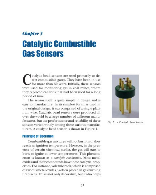
<strong>Catalytic</strong> bead sensors are used primarily to detect<br />
combustible gases. They have been in use<br />
for more than 50 years. Initially, these sensors<br />
were used for monitoring gas in coal mines, where<br />
they replaced canaries that had been used for a long<br />
period of time.<br />
The sensor itself is quite simple in design and is<br />
easy to manufacture. In its simplest form, as used in<br />
the original design, it was comprised of a single platinum<br />
wire. <strong>Catalytic</strong> bead sensors were produced all<br />
over the world by a large number of different manufacturers,<br />
but the performance and reliability of these<br />
sensors varied widely among these various manufacturers.<br />
A catalytic bead sensor is shown in Figure 1.<br />
Principle of Operation<br />
Combustible gas mixtures will not burn until they<br />
reach an ignition temperature. However, in the presence<br />
of certain chemical media, the gas will start to<br />
burn or ignite at lower temperatures. This phenomenon<br />
is known as a catalytic combustion. Most metal<br />
oxides and their compounds have these catalytic properties.<br />
For instance, volcanic rock, which is comprised<br />
of various metal oxides, is often placed in gas burning<br />
fireplaces. This is not only decorative, but it also helps<br />
Fig. 1<br />
A <strong>Catalytic</strong> <strong>Bead</strong> <strong>Sensor</strong><br />
37
D.C. POWER<br />
Hazardous Gas Monitors<br />
Reference <strong>Bead</strong><br />
OUTPUT<br />
Active <strong>Bead</strong><br />
R B<br />
R B<br />
R 1<br />
Fig. 2 A catalytic bead sensor<br />
Wheatstone bridge–a circuit for<br />
measuring an unknown resistance<br />
by comparing it with known<br />
resistances.<br />
the combustion process and results in cleaner and<br />
more efficient burning in the fireplace. Platinum,<br />
palladium, and thoria compounds are also excellent<br />
catalysts for combustion. This explains why the automobile<br />
exhaust system is treated with platinum compounds<br />
and is called a catalytic converter. This kind<br />
of gas sensor is made on the basis of the catalytic principle,<br />
and therefore is called the catalytic gas sensor.<br />
A gas molecule oxidizes on the catalyzed surface<br />
of the sensor at a much lower temperature than its<br />
normal ignition temperature. All electrically conductive<br />
materials change their conductivity as temperature<br />
changes. This is called the coefficient of temperature<br />
resistance (Ct). It is expressed as the percentage of<br />
change per degree change in temperature.<br />
Platinum has a large Ct in comparison to other<br />
metals. In addition, its Ct is linear between 500°C to<br />
1000°C, which is the temperature range at which the<br />
sensor needs to operate. Because the signal from the<br />
sensor is linear, this means that the concentration of<br />
gas readings are in direct proportion to the electrical<br />
signal. This improves the accuracy and simplifies the<br />
electronic circuitry. Also, platinum possesses excellent<br />
mechanical properties. It is physically strong and<br />
can be transformed into a fine wire which can be processed<br />
into small sensor beads.<br />
Furthermore, platinum has excellent chemical<br />
properties. It is corrosion resistant and can be operated<br />
at elevated temperatures for a long period of time<br />
without changing its physical properties. It is capable<br />
of producing a constant reliable signal over an extended<br />
period of time.<br />
The electrical circuit used to measure the output<br />
of catalytic sensors is called a Wheatstone bridge, in honor<br />
of English physicist and inventor Sir Charles Wheatstone<br />
(1802-75). Wheatstone bridges are commonly<br />
used in many electrical measurement circuits. As<br />
shown in Figure 2, four circuit branches are arranged<br />
38
Chapter 3<br />
<strong>Catalytic</strong> Combustible Gas <strong>Sensor</strong>s<br />
in a square. The source of the electrical current is connected,<br />
and between the other pair of opposite corners,<br />
the output measurement circuit is connected.<br />
In operation, R 1<br />
is the trim resistor that keeps the<br />
bridge balanced. A balanced bridge has no output signal.<br />
Resistor value R B<br />
and trim pot R 1<br />
are selected with<br />
relatively large resistance values to ensure proper function<br />
of the circuit. When the gas burns on the active<br />
sensor surface, the heat of combustion causes the temperature<br />
to rise, which in turn changes the resistance<br />
of the sensor. As the bridge is unbalanced, the offset<br />
voltage is measured as the signal. It is important that<br />
the reference sensor or bead maintains a constant resistance<br />
during the exposure to the combustible gas;<br />
otherwise, the measured signal will be inaccurate.<br />
Evolution of the sensor. The original catalytic sensor<br />
was a coil-shaped platinum wire. The coiled shape,<br />
illustrated in Figure 3, was used to obtain a compact<br />
geometry for efficient heating and to produce a strong<br />
enough signal to function as a gas sensor. Unfortunately,<br />
despite the excellent physical and chemical<br />
properties of platinum, it is a poor catalyst for combustion<br />
of hydrocarbon gases.<br />
For the proper detection of hydrocarbon gases,<br />
the sensor requires a heated surface temperature between<br />
900°C and 1000°C so that the sensor can properly<br />
react with gases at a sufficiently high and stable<br />
rate. At this temperature, however, the platinum starts<br />
to evaporate. The evaporation rate increases as the<br />
gas molecules start to react with the sensor and as the<br />
sensor temperature increases. This causes a reduction<br />
in the cross-section of the platinum wire, and, as<br />
a result, the resistance increases. This affects the<br />
sensor’s operating temperature, which shows up as zero<br />
and span drifts.<br />
The reference wire ideally should be the same as<br />
the active wire, with the same geometry and operating<br />
temperature, but should be nonreactive with the<br />
Fig. 3 Hot Wire <strong>Sensor</strong><br />
39
Hazardous Gas Monitors<br />
gas. This is not practically possible, however. A compromise<br />
is made by operating the reference wire at a<br />
temperature that is substantially lower so that no oxidation<br />
takes place in the presence of hydrocarbons.<br />
In addition, the reference wire is chemically treated<br />
to reduce the catalytic property of the platinum. This<br />
may also be achieved by coating platinum wire with a<br />
non-catalytic metal, such as gold.<br />
Another problem with hot platinum wire is that it<br />
becomes very soft at a temperature of 1000°C. Therefore,<br />
it is difficult to maintain its coil shape. Also, the<br />
coefficient of thermal resistance becomes less linear<br />
as the temperature increases. This situation also results<br />
in poor zero and span quality of the sensor, as<br />
well as a relatively short operating life.<br />
One way to improve stability of the sensor is to<br />
coat the platinum wire with suitable metal oxides.<br />
Thus, the final step is to treat the finished sensor or<br />
bead with a catalyst, such as platinum, palladium or<br />
thoria compounds. Figure 4, shows the sensor bead.<br />
CATALYTICALLY-TREATED<br />
METAL OXIDE<br />
PLATINUM WIRE<br />
Fig. 4<br />
A <strong>Catalytic</strong> <strong>Bead</strong> <strong>Sensor</strong><br />
The construction of the catalytic sensor bead is<br />
analogous to constructing a building by using reinforced<br />
concrete. The coating makes the sensor physically<br />
very rugged. The sensor becomes a very small<br />
40
Chapter 3<br />
<strong>Catalytic</strong> Combustible Gas <strong>Sensor</strong>s<br />
mass which helps make it resistant to shock and vibrations.<br />
Most importantly, the catalyst coating reduces<br />
the temperature needed to achieve a stable signal for<br />
hydrocarbons between 400°C and 600 o C.<br />
The use of fine diameter wire not only reduces<br />
the size of the sensor, but it also increases the signal,<br />
because finer wire has a higher magnitude of resistive<br />
value and the signal output is the percentage change<br />
of total wire resistance. This also reduces power consumption.<br />
The reference sensor can be constructed in the<br />
same way as the active sensor, with the exception that<br />
the catalyst chemical is eliminated. The bead can be<br />
further treated with chemicals, such as potassium, to<br />
prevent the reference bead from reacting with the gas.<br />
A near perfectly compensated pair of sensors is now<br />
possible. The sensor is called a “catalytic” sensor because<br />
the use of the catalyst is the main ingredient<br />
involved in the proper functioning of the sensor. The<br />
catalytic sensor is stable, reliable, accurate, and rugged,<br />
and has a long operating life. The output is linear<br />
because the platinum wire has a good linear coefficient<br />
of thermal resistance.<br />
Characteristics<br />
The sensor’s output is directly in proportion to<br />
the rate of oxidation. The maximum output of the<br />
signal occurs at about the stoichiometric 1 mixture of<br />
the gas, or it is based on the theoretical combustion<br />
reaction formula. Methane, for example:<br />
1<br />
Pertaining to substances that are in the<br />
exact proportions required for a given reaction.<br />
CH 4<br />
+ 2O 2<br />
+ 8N 2<br />
→ CO 2<br />
+ 2H 2<br />
O + 8N 2<br />
It takes 10 moles of air for one mole of methane<br />
to complete the reaction, assuming there is one part<br />
of oxygen and four parts of nitrogen in air.<br />
Therefore, for a theoretical combustion to take<br />
place, one part of methane will require 10 parts of air<br />
41
Hazardous Gas Monitors<br />
to complete the combustion, or theoretically 9.09%<br />
of methane in a mixture of air.<br />
For a sensor to detect methane, the signal output<br />
will respond linearly from 0–5% of methane<br />
(which is 100%LEL). As the concentration reaches<br />
close to the stoichiometric value of 9%, the signal<br />
increases very rapidly and peaks at around 10%. The<br />
signal starts to drop slowly as the concentration of<br />
gas passes approximately 20%; after 20% it drops<br />
straight down to a level that reflects no output as the<br />
concentration of gas reaches 100%. Figure 5, illustrates<br />
this effect.<br />
0-3%: NEARLINEAR; 3-5%: SLIGHTLY LESS LINEAR<br />
LEL<br />
UEL<br />
10<br />
8<br />
<strong>Sensor</strong> Output<br />
in volts<br />
6<br />
4<br />
2<br />
0<br />
5 10 15 20 40 60 80 100<br />
% Methane Gas Concentration<br />
Fig. 5 <strong>Sensor</strong> Output vs. Gas Concentration<br />
Consider another example, propane. The reaction<br />
formula for propane is:<br />
C 3<br />
H 8<br />
+ 5O 2<br />
+ 20 N 2<br />
→ 3CO 2<br />
+4H 2<br />
O + 20N 2<br />
or one part of propane per 25 parts of air for theoretical<br />
combustion of propane. The actual theoretical<br />
combustion concentration for propane is 3.85%.<br />
The LEL for methane is 5% and for propane is<br />
2.1%. This value is near half of the theoretical combustion<br />
value. There is a safety factor of 2 added to<br />
ensure safety.<br />
42
Chapter 3<br />
<strong>Catalytic</strong> Combustible Gas <strong>Sensor</strong>s<br />
<strong>Sensor</strong> Operation Factors<br />
There are several factors affecting the operation<br />
of the catalytic sensor.<br />
1. Catalyst Poisoning: There are chemicals which<br />
will deactivate the sensor and cause the sensor to lose<br />
sensitivity and eventually become totally nonresponsive<br />
to gases. The most common chemicals that can<br />
poison catalytic sensors are those that contain silicon,<br />
such as the common oil and lubricants with silicon<br />
compounds used as additives in machinery. Sulfur<br />
compounds, which are often released with gases, chlorine,<br />
and heavy metals also cause the poisoning of the<br />
sensor.<br />
The exact cause of this poisoning is very difficult<br />
to identify. Some chemicals, with very small concentrations,<br />
will totally destroy the sensor. There have been<br />
instances in which the silicon contained in simple<br />
hand lotions has caused problems with catalytic sensors.<br />
2. <strong>Sensor</strong> Inhibitors: Chemicals such as halogen<br />
compounds, which are used in fire extinguishers and<br />
Freon used in refrigerants, will inhibit the catalytic<br />
sensor and cause it to temporarily lose the ability to<br />
function.<br />
Normally, after 24 or 48 hours of exposure to ambient<br />
air, the sensor starts to function normally. These<br />
are just a few typical chemicals that inhibit the sensor<br />
performance and are by no means to be considered<br />
as the sole possible inhibitors.<br />
3. <strong>Sensor</strong> Cracking: The sensor, when exposed<br />
to excessive concentration of gases, excessive heat,<br />
and the various oxidation processes that take place<br />
on the sensor surface, may eventually deteriorate.<br />
Sometimes this will change the zero and span setting<br />
of the sensor.<br />
4. Correction Factors: <strong>Catalytic</strong> sensors are most<br />
43
Hazardous Gas Monitors<br />
Relative Sensitivity<br />
As an example for a typical sensor<br />
calibrated for 100% LEL methane<br />
gas, the relative sensitivity to<br />
other gases is as follows:<br />
Gas<br />
Reading<br />
Methane 100%<br />
Propane 60%<br />
n-Butane 60%<br />
n-Pentane 50%<br />
n-Hexane 45%<br />
Methanol 100%<br />
Ethanol 70%<br />
iso-Propyl Alcohol 60%<br />
Acetone 60%<br />
Methyl Ethyl Ketone 50%<br />
Toluene 45%<br />
commonly calibrated to methane for 0-100% LEL full<br />
scale range.<br />
The manufacturers generally provide a set of correction<br />
factors that allow the user to measure different<br />
hydrocarbons by simply multiplying the reading by<br />
the appropriate correction factor to obtain the reading<br />
of a different gas. The reason for using methane<br />
as the primary calibration gas is that methane has a<br />
saturated single bond that requires the sensor to operate<br />
at the highest temperature in comparison to<br />
other hydrocarbons. For instance, a typical catalytic<br />
sensor for methane gas may require a 2.5-volt bridge<br />
voltage to obtain a good signal, while the same sensor<br />
will only need 2.3 volts for butane gas. Therefore, if<br />
the sensor is set to read butane, it will not read methane<br />
properly.<br />
In addition, methane gas is a very common gas<br />
and is often encountered in many applications. Furthermore,<br />
it is also easy to handle and has the ability<br />
to be mixed into different concentrations easily.<br />
However, it should be noted that the correction factors<br />
are a set of numbers that should be used with<br />
great care. The correction factors can vary from sensor<br />
to sensor, and they can even change on the same<br />
sensor as the sensor ages. Therefore, the best way to<br />
obtain precise readings for a specific gas is to actually<br />
calibrate the sensor to the gas of interest directly.<br />
5. Percent LEL for Mixtures of Hydrocarbons:<br />
For combustion to take place, the following requirements<br />
must be present:<br />
a. Combustible mixture<br />
b. Oxygen<br />
c. Ignition source<br />
This is sometimes referred to as the combustion<br />
triangle. But in real life, the process of igniting a combustible<br />
mixture is much more complicated. The en-<br />
44
Chapter 3<br />
<strong>Catalytic</strong> Combustible Gas <strong>Sensor</strong>s<br />
vironmental conditions, such as pressure, temperature,<br />
temperature of the ignition source, and even<br />
humidity can have an affect on the combustible mixture<br />
concentration.<br />
If two or more chemicals are involved, it is not even<br />
possible to calculate and determine the combustion<br />
range of the mixture. Therefore, it is best to consider<br />
the worst-case scenario and calibrate the sensor accordingly.<br />
Furthermore, a sensor calibrated at a percentage<br />
LEL for one gas cannot necessarily be used<br />
for other gases. Many instruments on the market today<br />
have a scale unit as a percentage of LEL without<br />
indicating that the unit is calibrated on methane.<br />
Therefore, if the unit is used for some other gas or<br />
mixture of gases, the data can be totally meaningless.<br />
For example, a catalytic sensor calibrated on methane<br />
produces lower readings when exposed to hydrocarbons<br />
of higher carbon content, while infrared instruments<br />
will produce much higher readings if exposed<br />
to a higher carbon content gas. This is a very<br />
common mistake made by many users of gas detection<br />
equipment.<br />
Summary<br />
A catalytic sensor is relatively easy to manufacture.<br />
However, the quality of the sensor varies quite drastically<br />
from one manufacturer to another.<br />
The overall technology of making a sensor for<br />
the market is more of an art than a predictable scientific<br />
event. This is particularly true in selecting,<br />
preparing and processing all the chemicals needed<br />
to make the final sensor. There are too many variables<br />
in the process that inhibit the making of a predictable<br />
final product. Therefore, most users of catalytic<br />
sensors select their sensors based on the reputation<br />
of the manufacturer.<br />
Typical Specifications<br />
for <strong>Catalytic</strong> <strong>Sensor</strong>s<br />
<strong>Sensor</strong> Type: Diffusion catalytic bead<br />
Temperature Range: –40 o C to +60 o C<br />
Response Time: 10 to 15 sec. to 90% of<br />
reading<br />
Accuracy: ±5%<br />
Repeatability: 2%<br />
Drift: 5–10% per year<br />
Life Expectancy: Up to 3 years; depending<br />
on application<br />
<strong>Sensor</strong>s can be remotely mounted up to<br />
2,000-3,000 meters, depending on the<br />
manufacturer and cable size used to wire<br />
the sensor.<br />
45