Pro Series Ii - Schnitz Racing
Pro Series Ii - Schnitz Racing
Pro Series Ii - Schnitz Racing

You also want an ePaper? Increase the reach of your titles
YUMPU automatically turns print PDFs into web optimized ePapers that Google loves.
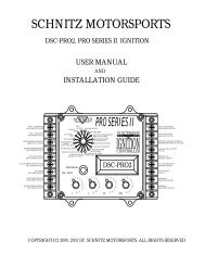
SCHNITZ MOTORSPORTS<br />
DSC-PRO2, PRO SERIES II IGNITION<br />
USER MANUAL<br />
AND<br />
INSTALLATION GUIDE<br />
<strong>Pro</strong>per Testing <strong>Pro</strong>cedures are included at the back of this manual.<br />
Failure to Follow these <strong>Pro</strong>cedures May and/or Will Damage the<br />
Controller and the Warranty will be Void!<br />
IMPORTANT - Read Technical Bulletins at the Back of this Manual<br />
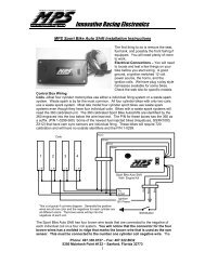
COIL 1,4 (OPTIONAL)<br />
16GA YELLOW, PAGE 23<br />
COIL 1,4 NEGATIVE<br />
16GA WHITE, PAGE 23<br />
FUEL SOLENOID (GROUND)<br />
GREEN 16GA , PAGE 25<br />
NOS SOLENOID (GROUND)<br />
16GA ORANGE, PAGE 25<br />
ACTIVATION INPUT<br />
20GA ORANGE, PAGE 25<br />
CLUTCH SWITCH INPUT (2-STEP)<br />
20GA YELLOW, PAGE 25<br />
KILL INPUT<br />
20GA GRAY, PAGE 26<br />
10<br />
11<br />
12<br />
13<br />
14<br />
15<br />
16<br />
ENGINE KILL TIME<br />
SCHNITZ<br />
MOTORSPORTS<br />
RUN<br />
OR VOLTS<br />
HIGH<br />
RPM<br />
LAUNCH<br />
RPM<br />
SHIFT RPM<br />
TRANSMISSION<br />
TYPE &<br />
SHIFT COUNTER<br />
TIMING ADVANCE RPM<br />
IGNITION TIMING<br />
RETARD & ADVANCE<br />
PROGRAM<br />
DSC-PRO2<br />
DIAGNOSTICS<br />
ENGINE RPM<br />
PRO SERIES II<br />
NOS 100% POWER DELAY<br />
TIME IN SECONDS<br />
NOS DELAY TIME<br />
IN SECONDS<br />
NOS START PERCENT<br />
NOS FINAL PERCENT<br />
NOS BUILD TIME<br />
IN SECONDS<br />
RETARD BUILD TIME<br />
IN SECONDS<br />
ELECTRONIC<br />
IGNITION<br />
CONTROLLER<br />
DSC-PRO2<br />
9 COIL 2,3 (OPTIONAL)<br />
16GA PURPLE, PAGE 23<br />
8<br />
7<br />
6<br />
5<br />
4<br />
3<br />
COIL 2,3 NEGATIVE<br />
16GA BLUE, PAGE 23<br />
GROUND, 14GA BLACK, PAGE 23<br />
TRIGGER (GROUND), 20GA BLACK<br />
ANALOG DATA OUTPUT<br />
PAGE 27<br />
TRIGGER +12V<br />
20GA RED, PAGE 23<br />
+12 VOLTS SWITCHED<br />
16GA RED, PAGE 23<br />
TACH OUTPUT<br />
PAGE 27<br />
SHIFT LIGHT GROUND<br />
20GA BROWN, PAGE 26<br />
17<br />
0<br />
1<br />
0<br />
1<br />
0<br />
1<br />
0<br />
1<br />
2<br />
TRIGGER 2,3<br />
20GA BLUE, PAGE 23<br />
2 3<br />
4<br />
5<br />
2 3<br />
4<br />
5<br />
2 3<br />
4<br />
5<br />
2 3<br />
4<br />
5<br />
SHIFT SOLENOID GROUND<br />
20GA GREEN, PAGE 26<br />
18 1<br />
1<br />
6<br />
7<br />
9<br />
8<br />
.1<br />
7<br />
8<br />
9<br />
6<br />
.01<br />
7<br />
8<br />
9<br />
6<br />
.001<br />
7<br />
8<br />
9<br />
6<br />
TRIGGER 1,4<br />
20GA WHITE, PAGE 23<br />
COPYRIGHT (C) 2000, 2001 BY, SCHNITZ MOTORSPORTS, ALL RIGHTS RESERVED<br />
1
IMPORTANT<br />
Stock Crankshaft Trigger will NOT work with this Controller.<br />
Use only DYNA PRO SERIES ® Trigger.<br />
Use only a Dual Magnet Rotor for Crankshaft Trigger.<br />
Use only .7ohm High Energy Ignition Coils. Part #DC9-1, DC9-2<br />
Use only Static Suppression Spark-plug Wires. Part #DW-800<br />
An Ignition Tester is available to simulate a running engine, Part #DCS-T01<br />
All items listed above are available from <strong>Schnitz</strong> <strong>Racing</strong>. 1-219-728-9730<br />
Notice of Copyright<br />
Copyright (C) 2000 <strong>Schnitz</strong> Motorsports, Decatur, Indiana. All rights reserved. Copyright<br />
law protects this document. It is unlawful to make copies, modify, or distribute without written<br />
consent from <strong>Schnitz</strong> Motorsports. It is the responsibility of the purchaser to follow all guidelines<br />
and safety procedures supplied with this product and any other manufactures product used with<br />
this product. It is also the responsibility of the purchaser to determine compatibility of this<br />
device with the vehicle and other components.<br />
<strong>Schnitz</strong> Motorsports assumes no responsibility for damages resulting from accident,<br />
improper installation, misuse, abuse, improper operation, lack of reasonable care, or all<br />
previously stated reasons due to incompatibility with other manufacturer's products.<br />
<strong>Schnitz</strong> Motorsports assumes no responsibility or liability for damages incurred from<br />
the use of products manufactured or sold by <strong>Schnitz</strong> Motorsports on vehicles used for<br />
competition racing.<br />
<strong>Schnitz</strong> Motorsports neither recommends nor approves the use of products<br />
manufactured or sold by <strong>Schnitz</strong> Motorsports on vehicles which may be driven on public<br />
highways or roads, and assumes no responsibility for damages incurred from such use.<br />
It is the purchaser’s responsibility to check the state and local laws pertaining to the use<br />
of Nitrous Oxide for racing applications. <strong>Schnitz</strong> Motorsports does not recommend nor condone<br />
the use of its products for illegal street racing.<br />
Caution<br />
Follow all recommended safety guidelines from this and other manufacturer installation<br />
guidelines. Never install any device, which pulsates nitrous solenoids without a safety solenoid<br />
installed. Static suppression ignition wires must be used with this unit! Mount the Ignition<br />
Controller as far away from secondary ignition components (ignition coils, ignition wires, etc.)<br />
As is physically possible.<br />
Installation of <strong>Schnitz</strong> Motorsports products signifies that you have read this<br />
document and agree to the terms stated within.<br />
Software updates are available. Software cost is $38.95 for all controllers that are more<br />
than 90 days old. Original sales receipt will be required for free software<br />
updates(controller less than 90 days old).<br />
Software Updates:<br />
MAXOP Version 6.2 - Re-calibrated Dwell Bias Voltage.<br />
MAXOP Version 6.3 - Improved Launch RPM.<br />
MAXOP Version 6.4 - Support for Remote Launch RPM Adjust Switch.<br />
MAXOP Version 6.5 - Made Shift Delay for 1-2 Shift Adjustable.<br />
MAXOP Version 7.0 - Precision Launch RPM Control, Calculated Ignition Retard Display.<br />
MAXOP Version 7.1 - Added Support for 1-2-3-4 Automatic Transmission.<br />
MAXOP Version 7.2 - Removed Support for Voltage Monitor.<br />
MAXOP Version 7.3 - Added Option for Pulsed or 100% Fuel Solenoid Output with Fuel Timer<br />
MAXOP Version 7.4 - Made Sequential Shift increment by RPM in Auto modes only.<br />
MAXOP Version 7.5 – Included support for NEW STYLE Stick Coils, .6 to 1.3 ohm resistance.<br />
2
<strong>Pro</strong> <strong>Series</strong> II<br />
Overview<br />
Description:<br />
The <strong>Pro</strong> <strong>Series</strong> II Ignition Controller is a highly integrated Digital Ignition System with<br />
innovative features that enable today’s racing technology to be utilized to its maximum potential.<br />
The system was designed to be simple while maintaining focus on features. This design<br />
technique has led to a controller that can be installed in hours not days, provided other<br />
operational systems have already been installed or are existing on the motorcycle.<br />
Features:<br />
A - Ignition System<br />
1 - The controller uses digital circuitry to precisely monitor and control the Inductive Type ignition<br />
drivers. This design enables precise and consistent ignition timing control from High Energy<br />
Ignition Coils. The High-Energy design ensures ignition performance for today’s technology.<br />
2 – Ignition Timing Control is integrated into the controller. A Timing Advance Feature has been<br />
added, This Feature can be turned on or off. The amount of Timing Advance as well as Advance<br />
RPM Range is fully adjustable. The Ignition Timing can be controlled either direction of Static<br />
Timing. You may Retard the Timing more than you advance it. There are three stages and types of<br />
timing retard available. The first stage or Initial Retard can range from 0 to 12 degrees. This stage is<br />
activated immediately when the <strong>Pro</strong>gressive Nitrous Timer System is activated. The second stage<br />
was designed with a progressive timer that applies timing control over a period of time. This stage<br />
is activated when the Nitrous Delay Timer times out. The second stage of retard can range from 0<br />
to 22 degrees and the <strong>Pro</strong>gressive Retard Timer can be programmed from .200 to 9.900 seconds.<br />
The third type of Timing Retard is a Start Retard function. The Start Retard can be set from 0 to 30<br />
degrees of Ignition Retard and is Only Active during Initial Engine Startup. This allows high<br />
compression engines to start easily and the Timing can be set to a point that will allow the engine<br />
to idle correctly. Read Start Retard <strong>Pro</strong>gramming Section for Important Information.<br />
IMPORTANT – The first and second stages of retard are added together when used<br />
together. Example: 1 st stage at 4 degrees and 2 nd stage at 12 degrees would provide a total<br />
of 16 degrees of timing retard.<br />
B – Features based on Engine RPM Control<br />
1 – High RPM, This selection enables the user to program an Upper RPM Limit for the engine.<br />
Valid RPM Range is from 3,000 to 16,000 RPM in 100-RPM Increments.<br />
2 – Launch RPM, This selection enables the user to program the RPM at which the engine and/or<br />
motorcycle leave starting line with. Applying +12V signal activates this stage of RPM control.<br />
Valid RPM Range is from 3,000 to 16,000 RPM in 100-RPM Increments.<br />
3 – Sequential Shift RPM, This selection enables the user to program the RPM at which the Shift<br />
Light Output becomes active and/or Auto Shifting can occur. A different RPM can <strong>Pro</strong>grammed<br />
for each gear, this is Sequential Shifting. The controller sequences through the User <strong>Pro</strong>grammed<br />
Shift Points. Shift Sequencing begins when the Activation terminal is ON. The Shift Light Output is<br />
ON any time engine RPM is above the Shift RPM Setting, and OFF whenever engine RPM falls<br />
below the Shift RPM. The Auto-Shift System is very flexible and can be configured for all popular<br />
transmission styles. There is an adjustable delay timer built in for the 1-2 shift, this helps to control<br />
short shifts due to wheel spin off the line. A built-in and adjustable shift counter keeps track of<br />
gear position and engine kill requirements. The shift counter also stops false shifting in top gear<br />
position. The shift system can programmed for automatic or manual shifting. The rider can do a<br />
manual or Shift Override at any time, even while in auto mode. The shift counter is updated<br />
internally when manual shifts occur also.<br />
Note - The Auto-Shift Function will NOT work with Air over Air Systems as<br />
Required for All <strong>Pro</strong> Classes.<br />
3
C – Integrated <strong>Pro</strong>gressive Nitrous System and <strong>Pro</strong>grammable Digital Timer System<br />
1 – The <strong>Pro</strong>gressive Nitrous System enables the user to adjust the NOS power curve for track<br />
and/or performance conditions.<br />
A – NOS Delay Timer, This selection enables the user to program a delay for the<br />
Start of NOS. The delay time can be set from 0.000 to 9.999 seconds. This delay<br />
Timer also determines when the 2 nd stage of ignition timing retard begins.<br />
B – NOS Starting Percent, This selection determines the amount of NOS that is delivered<br />
to the engine at the start of Nitrous Injection. By lowering the amount of Nitrous<br />
introduced into the engine initially, traction problems can be controlled to match track<br />
conditions. Range is from 0% (OFF), 10% to 100% in 1% increments.<br />
C – NOS Final Percent#1 and Final #2, This selection determines the final amount of<br />
Nitrous that will be delivered to the engine. By using Multiple Final Percentages a Dual<br />
Ramp can be Created giving much Greater Control of the Nitrous Power Curve. The<br />
Nitrous Power can Ramp Up or Down or Both Directions as needed. Range is from<br />
0%(OFF), 10% to 100% in 1% increments for both.<br />
D – NOS Build Time #1 and #2, This selection allows the user to adjust the amount of<br />
time it takes the Nitrous to go from Start Power to Final Power. A short time setting will<br />
make the Nitrous Power Curve very aggressive. And a longer setting would make the<br />
power curve less aggressive. The 2 nd Build Time begins after the 1 st Build Time has<br />
Finished. The Second Build Time can be Turned OFF by Setting it to 0.000 or Final% #2 at<br />
0%. Power Build Time ranges from .200 to 9.900 seconds.<br />
E - NOS 100% Power Digital Timer, This selection allows the user to select a point when<br />
the Nitrous System will go to 100%. By using a Third Timer the NOS can be <strong>Pro</strong>grammed<br />
to have Triple Power Ramps using 1 Stage of Nitrous. Please refer to the Section on<br />
<strong>Pro</strong>gramming the NOS 100% POWER DELAY for detailed examples.<br />
F - NOS Minimum and Maximum Activation RPM, This allows the user to set a RPM<br />
Range that the NOS is active in. These settings will shut off the NOS if the engine Bogs or<br />
is approaching the Rev Limiter<br />
G - NOS Shift Counter, This allows the user to Determine which Gear the Nitrous will<br />
Become Active. The NOS Shift Counter is Incremented each time the Sequential Shift<br />
Counter is Updated(Shift Light On and Back Off) or the Shift Input is Activated Signaling<br />
an Engine Kill Request. All Shifts are Counted after the Activation Terminal has had +12<br />
volts applied, even if the Activation Signal is Removed During Operation(User lets Off<br />
Throttle). This Function can be set to OFF and 2 nd to 6 th Gear.<br />
H - Pulsed or 100% Nitrous Fuel Output Option, This allows the user to tailor the<br />
Operation of the Fuel Solenoid Output to enhance fuel delivery characteristics. There is a<br />
Timer available for this option for Improved Tuning. Default setting is Fuel Solenoid<br />
Output pulsates and NOS Fuel 100% Timer is OFF.<br />
D – Diagnostics<br />
1 – The Diagnostics Menu allows the user to perform various tests on activation circuits and<br />
ignition coil output. The Static or Base ignition timing must be set using Diagnostic Mode. When the engine<br />
is running the Diagnostic selection automatically becomes a Digital Tachometer. This can be used to check<br />
Actual Launch RPM and adjust the settings as needed.<br />
2 - Enhanced Diagnostics that inform the user of potential problems. These include Crankshaft<br />
Trigger problems and Activation Switch Errors. Example - If a Trigger is producing an intermittent signal<br />
the Controller will Display an Error message on the screen. The Controller will also display an Error Code if<br />
one the Inputs become Erratic (i.e. - If the 2-step or Throttle switch is malfunctioning with the engine<br />
running the Controller will Warn the user of this condition and confirm which Input or Switch the Error<br />
occurred at.).<br />
3 - The Battery Voltage Monitor has been removed. This is to improve the controllers resistance to<br />
voltage spikes that may occur.<br />
E - Analog Data Output<br />
A - An Analog Output is provided for Data Logging Computers. This Output can be configured to<br />
provide information for the Ignition Timing or NOS Percent.<br />
4
Table of Contents<br />
Important Information and Cautions Page 2<br />
Overview of Controller and Features Page 3, 4<br />
Section 1, Setting Controller Parameters<br />
1.0 - The Basics of Setting Controller Parameters Page 6<br />
1.1 - Setting HIGH RPM, Upper RPM Limit Page 7<br />
1.2 - Setting LAUNCH RPM Page 7<br />
1.3 - Setting ENGINE KILL TIME for Air Shift Applications Page 7<br />
1.4 - Setting SHIFT RPM, SHIFT STYLE & SHIFT COUNTER Page 8<br />
1.5 - Setting 1-2 SHIFT DELAY TIMER Page 9<br />
1.6 - Setting IGNITION TIMING, RETARD and ADVANCE Page 9, 10<br />
1.7 - Setting Ignition TIMING ADVANCE RPM Page 10, 11<br />
1.8 - Setting RETARD BUILD TIME Page 12<br />
1.9 - Setting NOS 100% POWER DELAY TIME Page 12, 13<br />
1.10 - Setting NOS DELAY TIME Page 13<br />
1.11 - Setting NOS START PERCENT Page 13<br />
1.12 - Setting NOS FINAL PERCENT #1 Page 14<br />
1.13 - Setting NOS FINAL PERCENT #2 Page 14<br />
1.14 - Setting NOS BUILD TIME #1 Page 14<br />
1.15 - Setting NOS BUILD TIME #2 Page 15<br />
1.16 - Setting NOS MINIMUM ACTIVATION RPM Page 15<br />
1.17 - Setting NOS MAXIMUM ACTIVATION RPM Page 15<br />
1.18 - Setting NOS SHIFT COUNTER Page 16<br />
1.19 - Setting and Using the NOS FUEL OUTPUT OPTIONS Page 16<br />
Section 2, Diagnostics<br />
2.0 - Description of Diagnostic Functions Page 17<br />
2.1 - Ignition Coil Output Test Page 17<br />
2.2 - Testing ACTIVATION Input Page 17<br />
2.3 - Testing CLUTCH Switch Input (Launch RPM Control) Page 17<br />
2.4 - Testing KILL, SHIFT Input Page 17<br />
2.5 - Setting Ignition STATIC TIMING Page 18<br />
2.6 - Additional Information about Static Timing the Ignition Page 19<br />
2.7 - Setting the NOS FUEL OUTPUT OPTION Page 20<br />
2.8 - Setting the TACH OUTPUT FREQUENCY Page 20<br />
2.9 - Setting the ANALOG DATA Type Page 20<br />
2.10 - Testing the SELECT and DATA Switches Page 20<br />
2.11 - Error Codes Explained and Clearing Error Codes Page 21<br />
Section 3, Wiring Diagrams and Installation Instructions<br />
3.0 - Overview and Important Installation Instructions Page 22<br />
3.1 - Connecting the Ignition Components Page 23<br />
3.2 - Special Instructions for 4 Coil Systems Page 24<br />
3.3 - Connecting the Nitrous Oxide System Page 25<br />
3.4 - Connecting the Shift Light , Shift Solenoid Page 26<br />
3.5 - Electrical Specifications Page 27<br />
Tech Tips<br />
4.0 - How to Run without NOS Page 28<br />
4.1 - Testing the Auto-Shift System Page 28<br />
Warranty Information<br />
5.0 - Warranty Page 28<br />
5
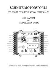
1.0 - The Basics of Setting Controller Parameters<br />
1 - Select Switch<br />
SCHNITZ<br />
MOTORSPORTS<br />
RUN<br />
OR VOLTS<br />
HIGH<br />
RPM<br />
LAUNCH<br />
RPM<br />
SHIFT RPM<br />
TRANSMISSION<br />
TYPE &<br />
SHIFT COUNTER<br />
ENGINE KILL TIME<br />
TIMING ADVANCE RPM<br />
IGNITION TIMING<br />
RETARD & ADVANCE<br />
PRO SERIES II<br />
DIAGNOSTICS<br />
ENGINE RPM<br />
NOS 100% POWER DELAY<br />
TIME IN SECONDS<br />
NOS DELAY TIME<br />
IN SECONDS<br />
NOS START PERCENT<br />
NOS FINAL PERCENT<br />
NOS BUILD TIME<br />
IN SECONDS<br />
RETARD BUILD TIME IN<br />
SECONDS<br />
ELECTRONIC<br />
IGNITION<br />
CONTROLLER<br />
TIMER DURATION<br />
PROGRAM<br />
DSC-PRO2<br />
DSC-PRO2<br />
0<br />
1<br />
0<br />
1<br />
0<br />
1<br />
0<br />
1<br />
1<br />
2<br />
3<br />
4<br />
5<br />
6<br />
7<br />
9<br />
8<br />
.1<br />
2<br />
3<br />
4<br />
5<br />
6<br />
7<br />
9<br />
8<br />
.01<br />
2<br />
3<br />
4<br />
5<br />
6<br />
7<br />
9<br />
8<br />
.001<br />
2<br />
3<br />
4<br />
5<br />
6<br />
7<br />
9<br />
8<br />
2 - <strong>Pro</strong>gramming Switch 3 - Data Switches<br />
Switch Descriptions and Functions<br />
1 - Switch #1 is the FUNCTION SELECT SWITCH, This switch is used<br />
to select which parameter is displayed and also selects that<br />
parameter for programming.<br />
2 - Switch #2 is the PROGRAM SWITCH, When this switch is pressed<br />
down and held for 2-seconds the DATA switches will be read and<br />
the settings will be programmed into the controller. If an<br />
INVALID setting is read the controller will NOT save the setting and<br />
will display an INVALID message on the display.<br />
3 - Data Switches #3 are for entering RPM Data, Ignition Retard Data,<br />
NOS Control Data, and for selecting various options as described<br />
in the following pages.<br />
Example <strong>Pro</strong>gramming Sequence<br />
Function Select Switch(#1) set to HIGH RPM (Switch pointing to HIGH RPM)<br />
Data Switch 1 set at 1, .01 at 2, .001 at 5, .001 at 0<br />
Data Switch 1 x 10,000 RPM<br />
Data Switch .1 x 1,000 RPM<br />
Data Switch .01 x 100 RPM<br />
Data Switch .001 is Ignored<br />
Pressing and holding PROGRAM Switch for 2-seconds will set the HIGH RPM<br />
at 12,500 RPM.<br />
Please refer to each of the following sections for setting all Functions.<br />
6
1.1 Setting HIGH RPM, Upper RPM Limit<br />
Set SELECT Switch to HIGH RPM.<br />
Example that would set HIGH RPM at 10,400<br />
1 set at 1<br />
.1 set at 0<br />
.01 set at 4<br />
.001 set at 0<br />
Press PROGRAM Button until the display reads PROGRAM. Release the button and the<br />
display will now read 10,400. HIGH RPM is now set at 10,400 RPM.<br />
Valid RPM range 3,000 to 16,000 RPM in 100-RPM Increments.<br />
Setting HIGH RPM to 0 will turn this function off.<br />
1.2 - Setting LAUNCH RPM<br />
Set SELECT Switch to LAUNCH RPM.<br />
Example that would set LAUNCH RPM at 7,200<br />
1 set at 0<br />
.1 set at 7<br />
.01 set at 2<br />
.001 set at 0<br />
Press PROGRAM Button until the display reads PROGRAM. Release the button and the<br />
display will now read 7,200. LAUNCH RPM is now set at 7,200 RPM.<br />
Valid RPM range 3,000 to 16,000 RPM in 100-RPM Increments.<br />
Setting LAUNCH RPM to 0 will turn this function off.<br />
1.3 – Setting ENGINE KILL TIME<br />
Set SELECT Switch to ENGINE KILL TIME<br />
Example that would set ENGINE KILL TIME at 85 milliseconds<br />
1 set at 0<br />
.1 set at 0<br />
.01 set at 8<br />
.001 set at 5<br />
Press the PROGRAM button until the display reads PROGRAM. Display will now read<br />
.085 and ENGINE KILL TIME is set at 85 milliseconds. Valid Time range .020 to .120<br />
second in .001 increments.<br />
7
1.4 – Setting SHIFT RPM, SHIFT STYLE & SHIFT COUNTER<br />
NOTE All Shift RPM’s MUST BE +/- 1,000 RPM of 1 st Shift RPM!<br />
Set SELECT Switch to the SHIFT RPM this is the 1 st Shift RPM<br />
When a NEW 1 st Shift RPM is <strong>Pro</strong>grammed all Shift RPM’s will be set to the 1 st Shift RPM Setting<br />
Automatically.<br />
Example that would set SHIFT RPM at 9,800<br />
1 set at 0<br />
.1 set at 9<br />
.01 set at 8<br />
.001 set at 0<br />
Press PROGRAM Button until the display reads PROGRAM. Release the button and the display will now read<br />
9,800. SHIFT LIGHT RPM is now set at 9,800 RPM. NOTE, IF the 1 st Shift RPM is <strong>Pro</strong>grammed it will take a<br />
couple of Seconds to Update the Following Shift RPM’s. Valid RPM range 3,000 to 16,000 RPM in 100-RPM<br />
Increments.<br />
NOTE: Only the 1 st SHIFT RPM will be used until the ACTIVATION Terminal is Activated.. This is done with a<br />
+12 volt signal. Please refer the next section for more information on the Auto-Shift System and its use.<br />
NOTE: Additional Shift RPM’s are set as follows.<br />
Set the SELECT Switch to TRANSMISSION TYPE & SHIFT COUNTER Use the .001 DATA Switch to Select the<br />
Desired Shift RPM to Set. You must turn the .001 DATA Switch to #2 to #5 positions to access the Sequential Shift<br />
RPM Settings. The Display will show the which Shift Point you have selected. After Selecting the Desired Shift<br />
RPM, It can be <strong>Pro</strong>grammed by using the Additional DATA Switches as outlined above.<br />
The Auto-Shift is NOT activated until the Activation terminal is armed. Applying +12 volts to the terminal does<br />
this. At this time of activation a 1-second timer will begin, NO AUTO SHIFTS will occur until this 1-second timer<br />
is done. This prevents sudden shifts due to wheel spin at the initial launch. A shift override may be activated at<br />
any time by applying +12V to the SHIFT Terminal. This is done with a shift button. A shift override will be<br />
counted by the AUTO-SHIFT shift counter. Ignition KILL for the shifts are controlled automatically by the<br />
controller. To use the SHIFT COUNTER with Manual shifting set the SHIFT STYLE as outline below. Auto Shift<br />
must be ACTIVATED for SHIFT COUNTER to work even when using MANUAL SHIFT Modes.<br />
SHIFT STYLE options are as follows:<br />
LITE<br />
No AUTO SHIFTING. Engine kill for all shifts. Manual Shift Only.<br />
1-2 LITE No AUTO SHIFTING. Will NOT kill for 1-2 shift. Manual Shift Only.<br />
1-2-3 LITE No AUTO SHIFTING. Will NOT kill for 1-2, 2-3 shifts. Manual Shift Only.<br />
1-2-3-4 LITE No AUTO SHIFTING. Will NOT kill for 1-2, 2-3, 3-4 shifts. Manual Shift Only.<br />
AUTOLITE No AUTO SHIFTING. Will NOT kill for all shifts. Manual Shift Only.<br />
STANDARD AUTO SHIFT ON. Will kill for all gears.<br />
1-2 AUTO AUTO SHIFT ON. Will NOT kill ignition for 1-2 shift.<br />
1-2-3 AUTO AUTO SHIFT ON. Will NOT kill ignition for 1-2-3 shifts.<br />
1-2-3-4 AUTO AUTO SHIFT ON. Will NOT kill ignition for 1-2-3-4 shifts.<br />
FUL AUTO AUTO SHIFT ON. Will NOT kill ignition for all shifts.<br />
NOTE - The shift counter, kill pattern will only increment to the next position by RPM when in Auto modes of<br />
operation. When used with an Air over Air system an auto mode must be selected to recognize gear changes by RPM.<br />
When in manual modes of operation a Shift-Kill input must be recognized before the shift counter will increment to the next<br />
gear position.<br />
To change the SHIFT STYLE setting set the SELECT Switch to SHIFT STYLE & SHIFT COUNTER. Set the .001<br />
DATA switch to 0. Pressing the PROGRAM button at this time will select the next option available. All option<br />
may be viewed by pressing the PROGRAM button repeatedly.<br />
SHIFT COUNTER options are as follows:<br />
2-SPEED<br />
No Auto-Shifts after 1 to 2 shift.<br />
3-SPEED<br />
No Auto-Shifts after 2 to 3 shift.<br />
4-SPEED<br />
No Auto-Shifts after 3 to 4 shift.<br />
5-SPEED<br />
No Auto-Shifts after 4 to 5 shift.<br />
6-SPEED<br />
No Auto-Shifts after 5 to 6 shift.<br />
To change the SHIFT COUNTER setting set the SELECT Switch to SHIFT STYLE & SHIFT COUNTER. Set the .001<br />
DATA switch to 1. Pressing the PROGRAM button at this time will select the next option available. All options<br />
may be viewed by pressing the PROGRAM button repeatedly.<br />
8
1.5 – Setting 1-2 SHIFT DELAY TIMER<br />
Set SELECT Switch to TRANSMISSION TYPE & SHIFT COUNTER<br />
Note - #.001 Data Switch must be set at 6<br />
Example that would set 1-2 SHIFT DELAY TIMER to .200 second.<br />
1 set at 0<br />
.1 set at 2<br />
.01 set at 0 - Not Used<br />
.001 set at 6 - Used to Select Shift Delay Function<br />
Press PROGRAM button until the display reads PROGRAM. Display will now read 0.200 and the<br />
SHIFT DELAY TIMER is .200 seconds. Valid range is 0.000 to 1.000 second in .100 increments.<br />
1.6 – Setting IGNITION TIMING, RETARD and ADVANCE<br />
Note - Initial RETARD and Build RETARD Settings are Added together for Amount of Total Ignition Timing<br />
RETARD.<br />
Setting INITIAL RETARD<br />
Set SELECT Switch to IGNITION TIMING, RETARD and ADVANCE<br />
Note - #1 Data Switch must be at 0<br />
Example that would set INITIAL RETARD to 6 degrees<br />
1 set at 0 - Used to select Timing Option<br />
.1 set at 0 (not used)<br />
.01 set at 0<br />
.001 set at 6<br />
Press PROGRAM button until the display reads PROGRAM. Display will now read INIT 6 and<br />
INITIAL RETARD is set to 6 degrees. Valid range 1 to 12 Degrees, 1Degree Increments. Setting to 0<br />
will turn this function/ OFF. NOTE: This retard stage will turn on immediately when the NOS<br />
Activation is turned on. (+12volts applied). The ignition retard will remain active until the NOS<br />
system resets.<br />
Setting Ignition Timing BUILD RETARD, 2 nd Stage of Retard<br />
Set SELECT Switch to IGNITION TIMING, RETARD and ADVANCE<br />
Note - #1 Data Switch must be set at 1<br />
Example that would set BUILD RETARD to 14 degrees<br />
1 set at 1 - Used to select Timing Option<br />
.1 set at 0 (not used)<br />
.01 set at 1<br />
.001 set at 4<br />
Press PROGRAM button until the display reads PROGRAM. Display will now read BUILD 14 and<br />
BUILD RETARD is set to 14 degrees. Valid range 1 to 22 Degrees, 1 Degree Increments. Setting to 0<br />
will turn this function OFF.<br />
NOTE: This retard stage will turn on when the NOS Delay Timer has timed out and the NOS<br />
Solenoids have been turned on. The retard will progressively come on based on the RETARD<br />
BUILD TIME setting.<br />
Viewing TOTAL Amount of Ignition Retard<br />
Set SELECT Switch to IGNITION TIMING, RETARD and ADVANCE<br />
Note - #1 Data Switch must be set at 2<br />
At this time the Display will show the Total amount of Ignition Timing Retard that will be<br />
applied when the NOS System is Activated.<br />
Viewing Calculated Ignition Timing Retard - This setting will display the actual Retard Calculated<br />
by the MCU when the NOS has been activated.<br />
Set SELECT Switch to IGNITION TIMING, RETARD and ADVANCE<br />
Note - #1 Data Switch must be turned to 5 to turn Option On. This option will remain in<br />
effect until power is removed from the controller. The display will show the Current Calculated<br />
Retard on the display anytime the NOS is activated regardless of the switch settings.<br />
9
Setting START RETARD<br />
Set SELECT Switch to IGNITION TIMING, RETARD and ADVANCE<br />
Note - #1 Data Switch must be at 4<br />
Example that would set START RETARD to 12 degrees<br />
1 set at 0 - Used to select Timing Option<br />
.1 set at 0 (not used)<br />
.01 set at 1<br />
.001 set at 2<br />
Press PROGRAM button until the display reads PROGRAM. Display will now read S RET: 12 and<br />
START RETARD is set to 12 degrees. Valid range 0 to 30 Degrees, 1Degree Increments. Setting to 0<br />
will turn this function OFF. NOTE: This retard stage is only Active During Engine Starting.<br />
Caution - If the Engine is Cranking Extremely Slow the Controller can NOT Calculate the proper Start Retard.<br />
In this case use the method outline below!<br />
Note - If the Start Retard is set to 34 degrees the Ignition will NOT Fire until the opposite side of the 2 nd Rotor<br />
Magnet. Guaranteed 34 Degrees of Start Retard. Please refer to Page 18.<br />
Setting Ignition Timing Degrees of ADVANCE<br />
NOTE - This Setting Does NOT have to be used(Set to 0). The Controller can adjust the Timing<br />
either direction(retard or advance) of Static Timing. Please Refer to Next Section regarding Timing<br />
Advance RPM Control.<br />
Set SELECT Switch to IGNITION TIMING<br />
Note - #1 Data Switch must be set at 3<br />
Example that would set ADVANCE to 10 degrees<br />
1 set at 3 - Used to select Timing Option<br />
.1 set at 0 (not used)<br />
.01 set at 1<br />
.001 set at 0<br />
Press PROGRAM button until the display reads PROGRAM. Display will now read ADV 10 and<br />
Timing ADVANCE is set to 10 degrees. Valid range 0 to 34 Degrees, 1 Degree Increments. Setting to<br />
0 will turn this function OFF.<br />
Note - The Degrees of Advance will be Added to the Static Timing of the Engine. Example - If the<br />
Static Timing is at 25 and Timing Advance Set at 10 the Total Ignition Timing Advance would be<br />
35 Degrees. The RPM at which the Timing Advance works is Fully <strong>Pro</strong>grammable and is<br />
Explained in the Next Section.<br />
1.7 – Setting Ignition TIMING ADVANCE RPM (Advance Curve)<br />
Note - These Settings along with Degrees of Timing Advance will Determine the Ignition Timing<br />
Advance Curve.<br />
Setting IGNITION TIMING BEGINNING ADVANCE RPM<br />
Set SELECT Switch to TIMING ADVANCE RPM<br />
Note - #.001 Data Switch must be set at 0<br />
IMPORTANT - The Beginning Advance RPM MUST be at Least 1,000 RPM Lower than the Full<br />
Timing Advance RPM. It may be necessary to Set the Full Timing Advance RPM First so the<br />
Timing Advance Beginning RPM can be set to the Desired Value.<br />
Example that would set TIMING ADVANCE Beginning RPM at 1,800 rpm<br />
1 set at 0<br />
.1 set at 1<br />
.01 set at 8<br />
.001 set at 0 - Used to Select Beginning and Full Timing Advance RPM<br />
Press PROGRAM button until the display reads PROGRAM. Display will now read 1,800 and<br />
TIMING ADVANCE Beginning RPM is set at 1,800 RPM. Valid RPM range 1,600 to 15,000 RPM in<br />
100-RPM Increments.<br />
10
Setting FULL TIMING ADVANCE RPM<br />
Set SELECT Switch to TIMING ADVANCE RPM<br />
Note - #.001 Data Switch must be set at 1<br />
IMPORTANT - This setting will determine the RPM at which Full Timing Advance is<br />
Reached.<br />
Example that would set FULL TIMING ADVANCE RPM at 4,800 rpm<br />
1 set at 0<br />
.1 set at 4<br />
.01 set at 8<br />
.001 set at 0 - Used to Select Beginning and Full Timing Advance RPM<br />
Press PROGRAM button until the display reads PROGRAM. Display will now read<br />
4,800 and FULL TIMING ADVANCE RPM is set at 4,800 RPM. Valid RPM range 2,600 to<br />
16,000 RPM in 100-RPM Increments.<br />
IMPORTANT INFORMATION: This setting is used along with DEGREES OF TIMING<br />
ADVANCE to adjust the Advance Curve for the ignition timing. The following<br />
information can be used to build almost any desired timing curve.<br />
CAUTION: Setting the Advance to High can Cause DETONATION which WILL HARM<br />
the engine. If you do not know where to set the ignition timing and advance setting<br />
then contact YOUR engine builder to obtain basic ignition timing information.<br />
Formula to Determine Advance Curve:<br />
Advance RPM Range = Full Timing Advance RPM - Timing Advance Beginning RPM<br />
RPM for 1 Degree of Advance = Advance RPM Range / Degrees of Timing Advance<br />
Degrees of Advance Per 1,000 RPM = 1000 / RPM for 1 Degree<br />
Example: ADVANCE BEGINING RPM = 1,800 rpm<br />
FULL TIMING ADVANCE RPM = 4,800 rpm<br />
DEGREES OF TIMING ADVANCE = 16 degrees<br />
Static Engine Timing = 20 degrees<br />
Total Timing Advance = 36 degrees<br />
4,800 - 1,800 = 3,000 (Advance RPM Range)<br />
3,000 / 16 = 187.5 (Every 187.5 RPM Increase will Advance Timing 1 Degree)<br />
1000 / 187.5 = 5.35 (Ignition Timing will Advance 5.35 Degrees every 1,000 RPM)<br />
Graph of Example Ignition Timing Curve<br />
DEGREES OF ADVANCE<br />
40<br />
35<br />
30<br />
25<br />
20<br />
15<br />
10<br />
5<br />
1,000 2,000 3,000 4,000 5,000 6,000 7,000 8,000 9,000 10,000<br />
ENGINE RPM<br />
11
1.8 - Setting RETARD BUILD TIME<br />
Set SELECT Switch to RETARD BUILD TIME IN SECONDS<br />
Example that would set RETARD BUILD TIME at 2.400 seconds<br />
1 set at 2<br />
.1 set at 4<br />
.01 set at 0 (not used)<br />
.001 set at 0 (not used)<br />
Press PROGRAM button until the display reads PROGRAM. Display will now read 2.400 and<br />
RETARD BUILD TIME is set at 2.400 seconds. Valid Time Range .200 to 9.900 seconds, .1 second<br />
Increments.<br />
Note: This setting determines the Ramp of IGNITION TIMING RETARD. A low setting i.e. (.200)<br />
will make the TIMING RETARD very aggressive. A high setting i.e. (9.900) will make the TIMING<br />
RETARD gradual.<br />
1.9 - Setting NOS 100% POWER DELAY TIME<br />
Set SELECT Switch to NOS 100% POWER DELAY TIME IN SECONDS<br />
Example that would set NOS 100% POWER DELAY at 4.000 seconds<br />
1 set at 4<br />
.1 set at 0<br />
.01 set at 0<br />
.001 set at 0<br />
Press PROGRAM button until the display reads PROGRAM. Display will now read 4.000 and NOS<br />
100% POWER DELAY is set to 4.000 seconds. Valid range 0.000 to 9.999 seconds in .001 second<br />
increments. Setting this to 0.000 turns off the NOS 100% POWER Function OFF.<br />
Example NOS Setups using <strong>Pro</strong>gressive and 100% Power Timers<br />
Example 1<br />
PERCENT OF NITROUS<br />
100<br />
90<br />
80<br />
70<br />
60<br />
50<br />
40<br />
30<br />
20<br />
10<br />
NOS DELAY<br />
NOS 100%<br />
POWER<br />
NOS PROGRESSIVE<br />
RAMP<br />
0.000 1.000 2.000 3.000 4.000 5.000 6.000 7.000 8.000 9.000<br />
TIME IN SECONDS<br />
NOS DELAY TIME = 0.500<br />
NOS FINAL% #1 = 80%<br />
NOS FINAL% #2 = OFF (0%)<br />
NOS BUILD TIME #1 = 8.000<br />
NOS BUILD TIME #2 = OFF (0.000)<br />
NOS 100% POWER DELAY = 5.000<br />
12
Example 2<br />
PERCENT OF NITROUS<br />
100<br />
90<br />
80<br />
70<br />
60<br />
50<br />
40<br />
30<br />
20<br />
10<br />
NOS DELAY<br />
NOS RAMP1<br />
NOS RAMP2<br />
0.000 1.000 2.000 3.000 4.000 5.000 6.000 7.000 8.000 9.000<br />
TIME IN SECONDS<br />
NOS DELAY TIME = 1.000<br />
NOS START% = 10%<br />
NOS FINAL% #1 = 30%<br />
NOS FINAL% #2 = 100%<br />
NOS BUILD TIME #1 = 4.000<br />
NOS BUILD TIME #2 = 2.000<br />
NOS 100% POWER DELAY = 0.000(OFF)<br />
1.10 – Setting NOS DELAY TIMER<br />
Set SELECT Switch to NOS DELAY TIME IN SECONDS<br />
Example that would set NOS DELAY TIME at 1.250 seconds<br />
1 set at 1<br />
.1 set at 2<br />
.01 set at 5<br />
.001 set at 0<br />
Press PROGRAM button until the display reads PROGRAM. Display will now read 1.250 and NOS<br />
DELAY TIME is set to 1.250 seconds.<br />
Valid range 0.000 to 9.999 seconds in .001 second increments.<br />
Note: This is timer to delay the start of NOS. A time of 0.000 will allow the NOS to start immediately<br />
when activated. Also the Ignition Timing BUILD Retard will NOT begin until this Delay Timer has<br />
timed out.<br />
1.11 – Setting the NOS START PERCENT<br />
Set SELECT Switch to NOS START PERCENT<br />
Example that would set NOS START PERCENT at 34%<br />
1 set at 0 (not used)<br />
.1 set at 0<br />
.01 set at 3<br />
.001 set at 4<br />
Press PROGRAM button until the display reads PROGRAM. Display will now read 34% and NOS<br />
START PERCENT is set at 34%. Valid Percentage Range 10 to 100% in 1% increments. Setting to 0%<br />
will turn NOS OFF even if NOS is Activated.<br />
Note: This setting allows the starting POWER developed from the NOS to be controlled for traction<br />
and other reasons.<br />
13
1.12 – Setting NOS FINAL PERCENT #1<br />
Set SELECT Switch to NOS FINAL PERCENT<br />
Example that would set NOS FINAL PERCENT #1 at 60%<br />
1 set at 0 - Used to Select Final% #1 or Final% #2<br />
1 set at 0<br />
.01 set at 6<br />
.001 set at 0<br />
Press PROGRAM button until the display reads PROGRAM. Display will now read 60%<br />
and NOS FINAL PERCENT #1 is set at 60%. Valid Percentage Range 10 to 100%, 1%<br />
Increments. Setting to 0% will turn NOS OFF even if NOS is Activated.<br />
1.13 – Setting NOS FINAL PERCENT #2<br />
Set SELECT Switch to NOS FINAL PERCENT<br />
Example that would set NOS FINAL PERCENT #2 at 100%<br />
1 set at 1 - Used to Select Final% #1 or Final% #2<br />
1 set at 1<br />
.01 set at 0<br />
.001 set at 0<br />
Press PROGRAM button until the display reads PROGRAM. Display will now read 100%<br />
and NOS FINAL PERCENT #1 is set at 100%. Valid Percentage Range 10 to 100%, 1%<br />
Increments. Setting Final% #2 to 0% will Disable the 2 nd Nitrous Ramp.<br />
1.14– Setting NOS BUILD TIME #1<br />
Set SELECT Switch to NOS BUILD TIME IN SECONDS<br />
Note: .001 Data Switch MUST be set at 0 to Set this Function.<br />
Example that would set NOS BUILD TIME #1 at 3.500 seconds<br />
1 set at 3<br />
.1 set at 5<br />
.01 set at 0 (not used)<br />
.001 set at 0 - Not used for Time Setting<br />
Press PROGRAM button until the display reads PROGRAM. Display will now read 3.500<br />
and NOS BUILD TIME #1 is set at 3.500 seconds. Valid Time Range .200 to 9.900 seconds<br />
in .1 second Increments.<br />
Note: This setting determines how fast the NOS goes from START PERCENT to FINAL<br />
PERCENT #1. A shorter BUILD TIME will make the NOS Power Curve more<br />
Aggressive.<br />
14
1.15 – Setting NOS BUILD TIME #2<br />
Set SELECT Switch to NOS BUILD TIME IN SECONDS<br />
Note: .001 Data Switch MUST be set at 1 to Set this Function.<br />
Example that would set NOS BUILD TIME #2 at 2.000 seconds<br />
1 set at 2<br />
.1 set at 0<br />
.01 set at 0 (not used)<br />
.001 set at 1 - Not used for Time Setting<br />
Press PROGRAM button until the display reads PROGRAM. Display will now read 2.000 and NOS<br />
BUILD TIME #2 is set at 2.000 seconds. Valid Time Range .200 to 9.900 seconds in .1 second<br />
Increments. Setting this Function to 0.000 will Turn OFF the 2 nd Nitrous <strong>Pro</strong>gressive Ramp.<br />
Note: This setting determines how fast the NOS goes from FINAL PERCENT #1 to FINAL<br />
PERCENT #2. A shorter BUILD TIME will make the NOS Power Curve more Aggressive.<br />
1.16 – Setting NOS MINIMUM ACTIVATION RPM<br />
Set SELECT Switch to NOS BUILD TIME IN SECONDS<br />
Note: .001 Data Switch MUST be set at 2 to Set this Function.<br />
Example that would set NOS MINIMUM ACTVATION RPM at 7,200<br />
1 set at 0<br />
.1 set at 7<br />
.01 set at 2<br />
.001 set at 2 - Not used for RPM Setting<br />
Press PROGRAM Button until the display reads PROGRAM. Release the button and the display will<br />
now read 7,200. NOS will now be Disabled when RPM is below 7,200.Valid RPM range 3,000 to<br />
16,000 RPM in 100-RPM Increments.<br />
1.17 – Setting NOS MAXIMUM ACTIVATION RPM<br />
Set SELECT Switch to NOS BUILD TIME IN SECONDS<br />
Note: .001 Data Switch MUST be set at 3 to Set this Function.<br />
Example that would set NOS MAXIMUM ACTVATION RPM at 11,200<br />
1 set at 1<br />
.1 set at 1<br />
.01 set at 2<br />
.001 set at 3 - Not used for RPM Setting<br />
Press PROGRAM Button until the display reads PROGRAM. Release the button and the display will<br />
now read 11,200. NOS will now be Disabled when RPM is over 11,200.Valid RPM range 3,000 to<br />
16,000 RPM in 100-RPM Increments.<br />
Note: This Setting should be set to RPM that is Lower than the High RPM Setting. This will allow the<br />
NOS to turn OFF before the Engine Rev Limiter is active.<br />
15
1.18 – Setting NOS SHIFT COUNTER<br />
Set SELECT Switch to NOS BUILD TIME IN SECONDS<br />
Note: .001 Data Switch MUST be set at 4 to Set this Function.<br />
The Display will read the Current NOS SHIFT COUNTER position. If the Display Reads OFF the<br />
NOS SHIFT COUNTER Function is Disabled and will NOT have any effect on the NOS System. If<br />
the Display Indicates a Gear Position then the NOS Timers will NOT begin Until the Shift Counter<br />
Has Reached the Selected Gear.<br />
To Turn OFF or Select the Desired Gear Position Press the PROGRAM Button until the display reads<br />
PROGRAM. Release the button and the NOS SHIFT COUNTER will Increment to the next Option.<br />
Note: The NOS SHIFT COUNTER must NOT be Set to a Higher Gear Position then the Shift<br />
Counter for the Sequential Shift Light Function or the NOS Timers will NOT become Active.<br />
1.19 – Setting and Using the NOS Fuel Output Options<br />
The NOS Fuel Solenoid Output can be configured to provide better tuning of the Fuel<br />
delivery. Below is a list of the possible combinations that can be programmed.<br />
1 - Fuel Solenoid is pulsed the same as the Nitrous Solenoid - Factory Default Setting<br />
2 - Fuel Solenoid goes to 100% immediately when the Start Percent begins.<br />
3 - Fuel Solenoid starts at 100% and begins pulsating after a pre-set time period.<br />
4 - Fuel Solenoid starts as normal(pulsating) and goes to 100% after a pre-set time period.<br />
Please refer to section 2.7 - Setting the NOS Fuel Output Option to Enable or<br />
Disable the Fuel 100% Start Option. The NOS Fuel 100% Timer can be used to<br />
control the NOS Fuel Solenoid Output as outlined below.<br />
Setting the NOS Fuel 100% Timer<br />
Set SELECT Switch to NOS BUILD TIME IN SECONDS<br />
Note: .001 Data Switch MUST be set at 5 to Set this Function.<br />
Example that would set NOS Fuel 100% Timer at 1.000 seconds<br />
1 set at 1<br />
.1 set at 0<br />
.01 set at 0 (not used)<br />
.001 set at 1 - Not used for Time Setting<br />
Press PROGRAM button until the display reads PROGRAM. Display will now read 1.000<br />
and NOS Fuel 100% Timer is set at 1.000 seconds. Valid Time Range 0.000 to 9.900 seconds<br />
in .1 second Increments.<br />
If the Fuel Output Option is set at PULSATE then the Fuel Solenoid will Pulsate with the<br />
Nitrous Solenoid until the NOS Fuel 100% Timer has elapsed and it will then go to 100%<br />
for the rest of the NOS Cycle.<br />
If the Fuel Output Option is set at 100% then the Fuel Solenoid will Start at 100% and<br />
begin pulsating with the Nitrous Solenoid when the NOS Fuel 100% Timer has elapsed.<br />
Setting this Function to 0.000 will Turn OFF the 100% Fuel Timer and the Fuel Solenoid<br />
Output will either Pulsate the entire NOS Cycle or the Fuel Output will immediately go to<br />
100% depending on the Setting of the Fuel Output Option in the Diagnostics Menu.<br />
16
Section 2, Diagnostics<br />
2.0 – Description of Diagnostic Functions<br />
The Diagnostics Functions will allow the user to test the output of the ignition coils, static time the<br />
ignition system, and test the activation inputs. These functions are only available if NO crankshaft<br />
movement has occurred. If the engine is running or has been turned over the diagnostics functions<br />
cannot be accessed. When the engine is running this selection automatically displays engine RPM on<br />
the display.<br />
2.1 – Ignition Coil Output Test<br />
Set the SELECT Switch to DIAGNOSTICS<br />
Press and HOLD the PROGRAM Switch until display reads RELEASE. Release the PROGRAM Switch at this<br />
time. The controller is now in the diagnostic mode.<br />
To perform an ignition coil output test set the .001 switch to 0.<br />
Press and release the PROGRAM switch. Each coil will be fired one time.<br />
Caution: The ignition coils will produce a high voltage spark. Use appropriate methods for testing.<br />
To exit diagnostics turn the .001 switch to 9. Then press and release the PROGRAM switch.<br />
2.2– Testing the ACTIVATION Input<br />
Set the SELECT Switch to DIAGNOSTICS<br />
Press and HOLD the PROGRAM Switch until display reads RELEASE. Release the PROGRAM Switch at this<br />
time. The controller is now in the diagnostic mode.<br />
To perform ACTIVATION Input test set the .001 switch to 2.<br />
At this time the DISPLAY will read ACTIVATE. If +12 volts is connected to the ACTIVATION terminal the<br />
Display will flash the message ACTIVE. Use this test to verify the ACTIVATION switche(s) on the bike.<br />
To exit diagnostics turn the .001 switch to 9. Then press and release the PROGRAM switch.<br />
2.3 - Testing the CLUTCH Switch Input<br />
Set the SELECT Switch to DIAGNOSTICS<br />
Press and HOLD the PROGRAM Switch until display reads RELEASE. Release the PROGRAM Switch at this<br />
time. The controller is now in the diagnostic mode.<br />
To perform CLUTCH (2-step) Input test set the .001 switch to 3.<br />
At this time the DISPLAY will read CLUTCH. If +12 volts is connected to the CLUTCH input terminal the<br />
Display would flash the message ACTIVE. Use this test to verify clutch/2-step switches on the bike.<br />
To exit diagnostics turn the .001 switch to 9. Then press and release the PROGRAM switch.<br />
2.4 – Testing KILL, SHIFT Input<br />
Set the SELECT Switch to DIAGNOSTICS<br />
Press and HOLD the PROGRAM Switch until display reads RELEASE. Release the PROGRAM Switch at this<br />
time. The controller is now in the diagnostic mode.<br />
To perform Engine Kill, Shift Input test set the .001 switch to 4.<br />
At this time the DISPLAY will read SHIFT. If +12 volts is connected to the SHIFT terminal the Display will flash<br />
the message ACTIVE. Use this test to verify the Shift switch.<br />
To exit diagnostics turn the .001 switch to 9. Then press and release the PROGRAM switch.<br />
17
2.5 – Setting Ignition Static Timing<br />
Set the SELECT Switch to DIAGNOSTICS<br />
Press and HOLD the PROGRAM Switch until display reads RELEASE. Release the<br />
PROGRAM Switch at this time. The controller is now in the diagnostic mode.<br />
To set the Static Timing set the .001 switch to 1.<br />
The display will read one of the following messages.<br />
STATIC - This shows the controller is in Static Timing Mode<br />
FIRE 1,4 - This shows when 1,4 cylinder will fire.<br />
FIRE 2,3 - This shows when 2,3 cylinder will fire.<br />
Note: Never Static Time the engine from the first trigger magnet. Only use the second<br />
magnet 90 degrees past the first magnet. Rotate the engine in the same direction as when<br />
running. The firing point for the spark is at the point where the display changes to the<br />
message FIRE *, *.<br />
To exit diagnostics turn the .001 switch to 9. Then press and release the PROGRAM switch.<br />
IMPORTANT: This is the BASE TIMING for the ignition. If you do NOT understand this<br />
setting, then contact YOUR engine builder for help.<br />
18
2.6 - STATIC TIMING SHEET - SCHNITZ IGNITIONS<br />
*** IMPORTANT INFORMATION ***<br />
SETTING IGNITION STATIC TIMING<br />
1 - INSTALL A DEGREE WHEEL AND LOCATE TOP DEAD CENTER AS<br />
OUTLINED WITH THE DEGREE WHEEL INSTRUCTIONS.<br />
IF YOU DO NOT HAVE A DEGREE WHEEL SCHNITZ RACING<br />
CARRIES THIS ITEM.<br />
THIS IS THE MOST ACCURATE WAY TO SET THE IGNITION<br />
TIMING. IF YOU DO NOT KNOW THE IGNITION TIMING SPECIFICATIONS<br />
FOR YOUR ENGINE, CONTACT YOUR ENGINE BUILDER FOR ASSISTANCE.<br />
2 - ENTER DIAGNOSTIC MODE AS OUTLINED IN THE INSTRUCTION<br />
MANUAL. SET THE .001 DATA SWITCH TO 1, THIS IS THE STATIC<br />
TIMING MODE.<br />
IMPORTANT: NEVER SET IGNITION TIMING BY ANY OTHER METHOD<br />
THAN THAT WHICH IS OUTLINED BY THIS INSTRUCTION SHEET.<br />
3 - AT THIS TIME THE DISPLAY SHOULD READ ONE OF THE FOLLOWING.<br />
STATIC - INDICATING STATIC TIMING MODE.<br />
FIRE 1,4 - THIS INDICATES #1,4 TRIGGER IS ACTIVE.<br />
FIRE 2,3 - THIS INDICATES #2,3 TRIGGER IS ACTIVE.<br />
TURN THE ENGINE THE DIRECTION OF NORMAL ROTATION.<br />
NOTE: THERE ARE 2 MAGNETS ON THE TRIGGER ROTOR. THE DISPLAY<br />
WILL INDICATE WHEN BOTH OF THESE MAGNETS ARE ALIGNED WITH<br />
THE TRIGGER. YOU MUST USE THE SECOND MAGNET, THE SECOND<br />
MAGNET IS THE ONE THAT FIRES THE IGNITION COIL.<br />
PLEASE NOTE THAT THE DISPLAY WILL INDICATE THE PRECISE<br />
TIME WHEN THE TRIGGER IS ACTIVATED BY THE ROTOR MAGNET. ADJUST<br />
THE TRIGGER PLATE OR TRIGGER ASSEMBLY TO OBTAIN THE CORRECT<br />
IGNITION TIMING.<br />
EXAMPLE SHOWING 1ST AND 2ND TIMING MAGNETS<br />
AT THIS TIME THE DISPLAY WOULD READ: FIRE 1,4<br />
ROTATION<br />
Ignition will fire here with Start Retard at 34 Degrees even<br />
if engine is cranking extremely slow.<br />
#2,3 ROTOR<br />
2ND<br />
#1,4<br />
Caution - The Engine Must Crank Over at a Moderate<br />
Speed for the Start Retard to Function <strong>Pro</strong>perly. If the<br />
Battery and/or Starter is Weak you must set the Start<br />
Retard to 34 degrees to insure proper Igntion Retard.<br />
1ST<br />
TRIGGER PLATE ASSEMBLY<br />
Leading Edge of 2nd Magnet. This is where the Static<br />
Ignition Timing is Set.<br />
19
2.7 - Setting the NOS Fuel Output Option<br />
Set the SELECT Switch to DIAGNOSTICS<br />
Press and HOLD the PROGRAM Switch until display reads RELEASE. Release the PROGRAM<br />
Switch at this time. The controller is now in the diagnostic mode.<br />
Set the .001 switch to 5. At this time the display will read one of the following.<br />
PULSATE - This setting indicates that the NOS Fuel Solenoid Output will Pulsate. The Optional NOS<br />
Fuel 100% Timer can be used to turn the Fuel Solenoid on to 100% before the NOS Build Time has<br />
finished(before the Nitrous Solenoid goes to 100%)<br />
100% - This setting indicates that the NOS Fuel Solenoid will start at 100%. The Optional NOS Fuel<br />
100% Timer can be used to start the Fuel Solenoid Pulsating after a pre-set amount time. It will then<br />
be at the same percentage as the Nitrous Solenoid and will go to the same Final Percent as the<br />
Nitrous Solenoid.<br />
NOTE – To toggle between the Options press and release the PROGRAM button.<br />
To exit diagnostics turn the .001 switch to 9. Then press and release the PROGRAM switch.<br />
2.8 – Setting the TACH OUTPUT FREQUENCY<br />
Set the SELECT Switch to DIAGNOSTICS<br />
Press and HOLD the PROGRAM Switch until display reads RELEASE. Release the PROGRAM<br />
Switch at this time. The controller is now in the diagnostic mode.<br />
Set the .001 switch to 6. At this time the display will read one of the following.<br />
TACH X2 - This setting indicates that the TACH OUTPUT will provide 2 output signals per<br />
revolution of the engine.<br />
TACH X1 - This setting indicates that the TACH OUTPUT will provide 1 output signal per<br />
revolution of the engine.<br />
NOTE – To toggle between X2 and X1 press and release the PROGRAM button.<br />
To exit diagnostics turn the .001 switch to 9. Then press and release the PROGRAM switch.<br />
2.9- Setting the ANALOG DATA Type<br />
Set the SELECT Switch to DIAGNOSTICS<br />
Press and HOLD the PROGRAM Switch until display reads RELEASE. Release the PROGRAM<br />
Switch at this time. The controller is now in the diagnostic mode.<br />
Set the .001 switch to 7, At this time the display will read one of the following.<br />
TIMING - This setting indicates that the ANALOG OUTPUT will provide an Analog Voltage that is<br />
proportional to the Current Ignition Timing. Refer to Specifications for Output Details.<br />
NOS - This setting indicates that the ANALOG OUTPUT will provide an Analog Voltage that is<br />
proportional to the Current NOS Percentage. Refer to Specifications for Output Details.<br />
NOTE – To toggle between Data Types press and release the PROGRAM button.<br />
To exit diagnostics turn the .001 switch to 9. Then press and release the PROGRAM switch.<br />
2.10- Testing the SELECT and DATA Switches<br />
Set the SELECT Switch to DIAGNOSTICS<br />
Press and HOLD the PROGRAM Switch until display reads RELEASE. Release the PROGRAM<br />
Switch at this time. The controller is now in the diagnostic mode.<br />
Set the .001 switch to 8. At this time the display will read SWITCH.<br />
To perform the Test, Press and Release the PROGRAM Button. The display will at first show<br />
Copyright Information and the Date of <strong>Pro</strong>gramming. After this these messages the display will<br />
show the current states of the Select and Data Switches. The switches may rotated at this time to<br />
verify that they are reading correctly. To exit diagnostics turn the .001 switch to 9. Then press and<br />
release the PROGRAM switch.<br />
20
2.11- Error Codes Explained and Clearing Error Codes<br />
The <strong>Pro</strong>-<strong>Series</strong> II Controller was designed with Self Diagnostics Features.<br />
These have been incorporated to Help the User Troubleshoot Wiring and/or<br />
Signal <strong>Pro</strong>blems. The Error Codes are Numbered and Each Code when Set will be<br />
Shown on the Display with a brief Description of the <strong>Pro</strong>blem Encountered. All<br />
Error Codes will Remain Until Cleared by the User. The Codes are Stored even if<br />
the Power is Removed from the Controller.<br />
IMPORTANT - If an Error Code is Set during Operation the Controller will Still<br />
Perform ALL Functions Except for <strong>Pro</strong>gramming. If the Controller can NOT Calculate<br />
Important Parameters needed for Ignition and/or RPM Related Functions Limited<br />
Operation will Result. NOS <strong>Pro</strong>gressive and Retard Timers are NOT Reset if an Error<br />
Occurs. RPM Related Functions will Resume After a Trigger Error if NO other Trigger<br />
Errors Occur.<br />
NOTE - If an Error Code is Set During Diagnostic Testing(Switch Input Test) follow<br />
the <strong>Pro</strong>cedure for Clearing the Code. The Code can be Set Inadvertently during<br />
Diagnostic Testing.<br />
List of Error Codes<br />
IGX-2001, Crankshaft Trigger 1,4 Sync Error - This Code indicates that the #1,4<br />
Crankshaft Trigger Signal was Intermittent while the Engine was Running. This Error<br />
Code could be caused by a Malfunctioning Trigger Assembly or Faulty Wiring and/or<br />
Connections.<br />
IGX-2002, Crankshaft Trigger 2,3 Sync Error - This Code indicates that the #2,3<br />
Crankshaft Trigger Signal was Intermittent while the Engine was Running. This Error<br />
Code could be caused by a Malfunctioning Trigger Assembly or Faulty Wiring and/or<br />
Connections.<br />
IGX-2003, Clutch Input Erratic - This Code indicates that the Clutch Input has Went from<br />
ON to OFF in a Erratic Pattern Indicating a Faulty Switch and/or Wiring.<br />
IGX-2004, Activation Input Erratic - This Code indicates that the Activation Input has<br />
Went from ON to OFF in a Erratic Pattern Indicating a Faulty Switch and/or Wiring. This<br />
Input is Most Commonly Controlled by a Wide Open Throttle Switch.<br />
IGX-2005, Shift Input Erratic - This Code indicates that the Clutch Input has Went from<br />
ON to OFF in a Erratic Pattern Indicating a Faulty Switch and/or Wiring. This Error Code<br />
can sometimes be set by a Poor Quality Switch such as a Factory Horn Button Used to<br />
Activate the Shift Solenoid and Engine Kill. It is Possible for this Code to be set by a<br />
malfunctioning Relay Used in the Air Shift System.<br />
Clearing Error Codes<br />
To Clear Stored Error Codes just Press the <strong>Pro</strong>gram Button until the Message RELEASE is<br />
shown on the Display. At this time the Error Code that was Stored in Memory is Cleared.<br />
NOTE - Multiple Error Codes are NOT Stored. Only the Most Recent Code is Stored and<br />
Displayed .<br />
21
Section 3, Wiring Diagrams and Installation Instructions<br />
3.0 – Overview and Important Installation Instructions<br />
Please read and follow all instructions carefully. It is important that the<br />
installation guidelines be followed for maximum performance.<br />
IMPORTANT - Do NOT mount the controller on rubber bushings. This only<br />
increases the vibration of the controller and can cause premature wear to the<br />
internal connections. If mounted to panels the panel should be connected to the<br />
frame close to and under the controller location.<br />
Guidelines:<br />
1 - If Stock Ignition Switch is used a SEPARATE POWER SOURCE for the<br />
NOS System is HIGHLY recommended. Please refer to NOS Instructions.<br />
2 - Use a good quality wire of recommended size.<br />
3 - Solder all connectors to the wire when professional crimp tools are not<br />
available.<br />
4 - Use shrink wrap to protect exposed terminals/wires.<br />
5 - Install the proper FUSE where required.<br />
6 - Use only the Required Ignition components.<br />
7 - Use quality switches.<br />
8 - Follow other manufacturer guidelines and recommendations when<br />
installing related components.<br />
9 - NEVER disregard SAFETY and/or CAUTION Warnings!<br />
10 - Mount all components correctly.<br />
Related Components Needed for Installation and Operation<br />
1 - Ignition Coils, DYNA (r) .7 ohm blue coils.<br />
2 - Static Suppression Ignition Wires ONLY!<br />
3 - Crankshaft Trigger, DYNA (s) or PRO SERIES (r)<br />
(DUAL magnet rotor ONLY!)<br />
4 - Nitrous System, Recommended NOS Kit (optional).<br />
(Use genuine NOS components for best results)<br />
5 – Throttle with Switch built in. Activation switches as needed.<br />
6 - Electric over air shift components (optional).<br />
IMPORTANT INFORMATION - The Controller will NOT turn on the NOS or<br />
SEQUENTIL-SHIFT Systems if the CLUTCH Input is Active(2-Step is ON). Installation<br />
of this Controller Requires a Throttle Switch even if the NOS System is NOT being<br />
used. This is to provide an Accurate Activation Signal to the Controller. Activate the<br />
Clutch Input(2-step) before opening the throttle all the way to provide the<br />
ACTIVATION Signal! Set the LAUNCH RPM to 0,000 (OFF) to Disable the Launch<br />
RPM if this Function is NOT Needed.<br />
22
KEEP ALL COIL WIRES SEPERATE FROM OTHER WIRING!<br />
COIL 1,4 NEGATIVE TERMINAL(4 COIL SYSTEM ONLY), YELLOW 16 GA<br />
COIL 1,4 NEGATIVE TERMINAL, WHITE 16 GA<br />
3.1 - Connecting the Ignition Components<br />
COIL 1,4(OPTIONAL)<br />
COIL 1,4 NEGATIVE<br />
FUEL SOLENOID (GROUND)<br />
PAGE 25<br />
NOS SOLENOID (GROUND)<br />
PAGE 25<br />
ACTIVATION INPUT<br />
PAGE 25<br />
CLUTCH SWITCH INPUT(2-STEP)<br />
PAGE 25<br />
KILL INPUT<br />
PAGE 26<br />
SHIFT LIGHT GROUND<br />
PAGE 26<br />
SHIFT SOLENOID GROUND<br />
PAGE 26<br />
NOTICE: If Installing a 4-Coil System READ PAGE 24<br />
10<br />
11<br />
12<br />
13<br />
14<br />
15<br />
16<br />
17<br />
18<br />
LEFT<br />
TERMINAL<br />
1ST COIL<br />
.7 OHM BLUE COIL<br />
2ND COIL<br />
.7 OHM BLUE COIL<br />
(OPTIONAL)<br />
LAUNCH<br />
RPM<br />
SCHNITZ<br />
MOTORSPORTS<br />
RUN<br />
OR VOLTS<br />
HIGH<br />
RPM<br />
IGNITION SWITCH<br />
PART# SCH-0048<br />
16 GA TO BATTERY + TERMINAL<br />
16 GA<br />
FUSE 10A<br />
FUSE 20A<br />
PRO SERIES II<br />
DIAGNOSTICS<br />
ENGINE RPM<br />
NOS 100% POWER DELAY<br />
TIME IN SECONDS<br />
NOS DELAY TIME<br />
IN SECONDS<br />
SHIFT RPM<br />
TRANSMISSION<br />
TYPE &<br />
NOS START PERCENT<br />
SHIFT COUNTER<br />
ENGINE KILL TIME<br />
NOS FINAL PERCENT<br />
NOS BUILD TIME<br />
TIMING ADVANCE RPM<br />
IN SECONDS<br />
IGNTION TIMING RETARD BUILD TIME IN<br />
RETARD & ADVANCE SECONDS<br />
PROGRAM<br />
DSC-PRO2<br />
0 1 2<br />
3<br />
4<br />
5<br />
6<br />
7<br />
8<br />
1 9<br />
0 1 2<br />
3<br />
4<br />
5<br />
6<br />
7<br />
8<br />
.1 9<br />
0 1 2<br />
3<br />
4<br />
5<br />
6<br />
7<br />
8<br />
.01 9<br />
POS+ NEG<br />
12 VOLT<br />
BATTERY<br />
RIGHT<br />
TERMINAL<br />
RED WIRE, 16GA, +12V FROM IGNITION SWITCH<br />
T1<br />
T3<br />
FUSE 20A<br />
TRIGGER 1,4 WHITE 20GA<br />
T4<br />
CAUTION: REMOVE COIL 20A FUSE(S)<br />
WHEN NOT IN USE. COILS MAY BE<br />
WIRED THROUGH IGNITION SWITCH<br />
ALSO, HOWEVER, THE METHOD SHOWN<br />
IS PREFERRED FOR EXTREME RACE<br />
CONDITIONS.<br />
ELECTRONIC<br />
IGNITION<br />
CONTROLLER<br />
DSC-PRO2<br />
.001<br />
0 1 2<br />
3<br />
4<br />
5<br />
6<br />
7<br />
9<br />
8<br />
IMPORTANT: MUST USE A DUAL MAGNET<br />
ROTOR AND .7 OHM (BLUE) IGNITION COILS!<br />
USE ONLY DYNA(R) DW-800 SUPPRESSION WIRES!<br />
INPUT<br />
OUTPUT<br />
TECH TIP - RUN GROUND WIRE FROM CONTROLLER<br />
STRAIGHT TO THE BATTERY NEG. USE ONLY ONE<br />
GROUND WIRE TO ENGINE. WHEN CONNECTING A<br />
GROUND LEAD FOR ITEMS NOT CONNECTED TO<br />
CONTROLLER ROUTE THE GROUND WIRE DIRECTLY<br />
TO THE BATERY NEG. TERMINAL.<br />
TRIGGER 2,3 BLUE 20GA<br />
BLACK<br />
T2<br />
IF CONTROLLER CASE IS NOT MOUNTED ON FRAME<br />
GROUND THEN A JUMPER WIRE SHOULD BE RAN<br />
FROM #7 TO MOUNTING BOLT<br />
DYNA S (R)<br />
PICKUP GROUND<br />
BLACK. 20GA<br />
COIL 2,3 (OPTIONAL)<br />
COIL 2,3 NEGATIVE<br />
GROUND<br />
TRIGGER GROUND<br />
+12 VOLTS SWITCHED<br />
WHITE<br />
NOTE:<br />
RED WIRING FOR PRO SERIES(R) PICKUP<br />
T1 - RED (+12V)<br />
T2 - BLACK (PICKUP GND)<br />
T3 - WHITE (TRIGGER 1,4)<br />
T4 - BLUE (TRIGGER 2,3)<br />
ENGINE GROUND<br />
ONE GROUND WIRE TO ENGINE<br />
9<br />
8<br />
7<br />
6<br />
5<br />
4<br />
3<br />
2<br />
1<br />
TRIGGER +12V, RED 20GA<br />
COIL POSITIVE, RED 16 GA<br />
1ST COIL<br />
.7 OHM BLUE COIL<br />
2ND COIL<br />
.7 OHM BLUE COIL<br />
(OPTIONAL)<br />
ANALOG DATA OUTPUT<br />
PAGE 27<br />
TRIGGER +12V<br />
TACH OUTPUT<br />
PAGE 27<br />
TRIGGER 2,3<br />
TRIGGER 1,4<br />
GROUND, BLACK 14 GA<br />
COIL 2,3 NEGATIVE TERMINAL, BLUE 16 GA<br />
KEEP ALL COIL WIRES SEPERATE FROM OTHER WIRING!<br />
COIL 2,3 NEGATIVE TERMINAL(4 COIL SYSTEM ONLY), PURPLE 16 GA<br />
23
3.2 - Special Instructions for 4 Coil Systems<br />
IMPORTANT<br />
Use Only Carbon Core Ignition Wires<br />
With a Resistance of 3000 Ohms<br />
Per Foot Minimum.<br />
On Dual Plug Systems, Never Connect BOTH<br />
OUTPUTS(Sparkplug Wires) to One Cylinder.<br />
Example: Do NOT Connect 1st Coil 1,4 Both<br />
Wires to Cylinder #1.<br />
The CORRECT Way To Wire the Ignition<br />
Coils is Shown Below.<br />
1st Coil, Cyl. 1,4<br />
2nd Coil, Cyl. 1,4<br />
.7 Ohm Blue Coil<br />
1st Coil 1,4 WHITE<br />
.7 Ohm Blue Coil<br />
2nd Coil 1,4 YELLOW<br />
Cylinder #2 Cylinder #3<br />
Cylinder #1<br />
Cylinder #4<br />
1st Coil, Cyl. 2,3<br />
2nd Coil, Cyl. 2,3<br />
.7 Ohm Blue Coil<br />
1st Coil 2,3 BLUE<br />
.7 Ohm Blue Coil<br />
2nd Coil 2,3 PURPLE<br />
24
CLUTCH SWITCH INPUT(2-STEP), YELLOW 20 GA<br />
3.3 - Connecting the Nitrous Oxide System<br />
NOTICE: ALL DIODES, CAPACITORS, AND FILTERS FROM PREVIOUS NOS INSTALLATIONS MUST BE<br />
REMOVED! FAILURE TO DO SO WILL RESULT IN UNDISIRABLE OPERATION OF THIS CONTROLLER.<br />
COIL 1,4 (OPTIONAL)<br />
PAGE 23<br />
COIL 1,4 NEGATIVE<br />
PAGE 23<br />
FUEL SOLENOID (GROUND)<br />
NOS SOLENOID (GROUND)<br />
ACTIVATION INPUT<br />
CLUTCH SWITCH INPUT (2-STEP)<br />
KILL INPUT<br />
PAGE 26<br />
SHIFT LIGHT GROUND<br />
PAGE 26<br />
SHIFT SOLENOID GROUND<br />
PAGE 26<br />
NOTE: NOS TIMERS WILL NOT BEGIN UNTIL 2-STEP IS OFF. THIS ALLOWS THE SYSTEM TO OPERATE<br />
WITHOUT RELAYS. IF +12 VOLTS IS APLLIED TO THE ACTIVATION TERMINAL WITHOUT THE<br />
CLUTCH INPUT ACTIVATED THE NOS, TIMER, AND SHIFT SYSTEMS WILL TURN ON.<br />
10<br />
11<br />
12<br />
13<br />
14<br />
15<br />
16<br />
17<br />
LAUNCH<br />
RPM<br />
SHIFT RPM<br />
RUN<br />
OR VOLTS<br />
HIGH<br />
RPM<br />
TRANSMISSION<br />
TYPE &<br />
SHIFT COUNTER<br />
ENGINE KILL TIME<br />
TIMING ADVANCE RPM<br />
SCHNITZ<br />
MOTORSPORTS<br />
IGNITION TIMING<br />
RETARD & ADVANCE<br />
PROGRAM<br />
DSC-PRO2<br />
0<br />
1 2<br />
3<br />
4<br />
5<br />
6<br />
7<br />
8<br />
1 9<br />
PRO SERIES II<br />
DIAGNOSTICS<br />
ENGINE RPM AND<br />
ELECTRONIC<br />
NOS 100% POWER DELAY<br />
TIME IN SECONDS<br />
IGNITION<br />
NOS DELAY TIME<br />
IN SECONDS<br />
NOS START PERCENT<br />
NOS FINAL PERCENT<br />
NOS BUILD TIME<br />
IN SECONDS CONTROLLER<br />
RETARD BUILD TIME IN<br />
SECONDS<br />
0<br />
1 2<br />
3<br />
4<br />
5<br />
6<br />
7<br />
8<br />
.1 9<br />
DSC-PROS2<br />
0<br />
1 2<br />
3<br />
4<br />
5<br />
6<br />
7<br />
8<br />
.01 9<br />
0<br />
1 2<br />
3<br />
4<br />
5<br />
6<br />
7<br />
8<br />
.001 9<br />
18 1<br />
9<br />
8<br />
7<br />
6<br />
5<br />
4<br />
3<br />
2<br />
COIL 2,3 (OPTIONAL)<br />
PAGE 23<br />
COIL 2,3 NEGATIVE<br />
PAGE 23<br />
GROUND & TRIGGER GROUND<br />
PAGE 23<br />
ANALOG DATA OUTPUT<br />
PAGE 27<br />
TRIGGER +12V<br />
PAGE 23<br />
+12 VOLTS SWITCHED<br />
PAGE 23<br />
TACH OUTPUT<br />
PAGE 27<br />
TRIGGER 2,3<br />
PAGE 23<br />
TRIGGER 1,4<br />
PAGE 23<br />
2-STEP BUTTON<br />
CONNECT TO IGNTION SWITCH OUTPUT<br />
PAGE 18<br />
16GA BLACK<br />
FUEL SOLENOID (GROUND), GREEN 16GA<br />
NOS SOLENOID (GROUND), ORANGE 16GA<br />
ACTIVATION INPUT, ORANGE 20 GA<br />
16GA RED<br />
THROTTLE ACTIVATED MICROSWITCH<br />
SWITCH ON ONLY WHEN THROTTLE<br />
IS WIDE OPEN. SWITCHED THROTTLE<br />
POS+ NEG<br />
12 VOLT<br />
BATTERY<br />
FUSE 20A<br />
FUSE 20A<br />
16GA RED<br />
ENGINE GROUND<br />
SEE PAGE 18<br />
NOS ARMING SWITCH<br />
DOUBLE POLE, SINGLE THROW<br />
NOTE - THIS SYSTEM IS DESIGNED TO BE USED WITH A THROTTLE SWITCH EVEN IF<br />
NOS SYSTEM IS NOT CONNECTED. IF NO NOS SYSTEM IS INSTALLED USE A TOGGLE<br />
SWITCH TO ARM THE ACTVATION SYSTEM(PROVIDES +12V FOR THROTTLE SWITCH).<br />
BY USING A THROTTLE SWITCH NO RELAYS ARE NEEDED. CONTROLLER IGNORES<br />
OTHER INPUTS WHILE 2-STEP IS ON(CLUTCTH INPUT ACTIVE).<br />
16GA RED<br />
NOS<br />
FUEL<br />
PUMP<br />
NEGATIVE<br />
POSITIVE<br />
NOTE: NOS SYSTEM CAN BE TURNED OFF BY<br />
SETTING EITHER START% OR FINAL% T0 0%<br />
THIS WILL ALLOW THE TIMER AND SHIFT<br />
SYSTEM TO BE ACTIVATED FROM THROTTLE<br />
SWITCH EVEN WHEN NO NOS IS DESIRED.<br />
FUEL<br />
SOLENOID<br />
NOS<br />
SOLENOID<br />
SAFETY<br />
SOLENOID<br />
GROUND<br />
25
3.4 - Connecting the Shift Light, Shift Solenoid<br />
NOTE: TIMERS WILL NOT BEGIN UNTIL 2-STEP IS OFF. THIS ALLOWS THE SYSTEM TO OPERATE<br />
WITHOUT RELAYS. IF +12 VOLTS IS APLLIED TO THE ACTIVATION TERMINAL WITHOUT THE<br />
CLUTCH INPUT ACTIVATED THE NOS, TIMER, AND SHIFT SYSTEMS WILL TURN ON.<br />
COIL 1,4 (OPTIONAL)<br />
PAGE 23<br />
COIL 1,4 NEGATIVE<br />
PAGE 23<br />
FUEL SOLENOID (GROUND)<br />
PAGE 25<br />
NOS SOLENOID (GROUND)<br />
PAGE 25<br />
ACTIVATION INPUT<br />
PAGE 25<br />
10<br />
11<br />
12<br />
13<br />
14<br />
HIGH<br />
RPM<br />
LAUNCH<br />
RPM<br />
SHIFT RPM<br />
TRANSMISSION<br />
TYPE &<br />
SHIFT COUNTER<br />
ENGINE KILL TIME<br />
TIMING ADVANCE RPM<br />
SCHNITZ<br />
MOTORSPORTS<br />
RUN<br />
OR VOLTS<br />
IGNITION TIMING<br />
RETARD & ADVANCE<br />
PRO SERIES II<br />
DIAGNOSTICS<br />
ENGINE RPM<br />
NOS 100% POWER DELAY<br />
TIME IN SECONDS<br />
NOS DELAY TIME<br />
IN SECONDS<br />
NOS START PERCENT<br />
NOS FINAL PERCENT<br />
NOS BUILD TIME<br />
IN SECONDS<br />
RETARD BUILD TIME IN<br />
SECONDS<br />
ELECTRONIC<br />
IGNITION<br />
CONTROLLER<br />
9<br />
8<br />
7<br />
6<br />
5<br />
COIL 2,3 (OPTIONAL)<br />
PAGE 23<br />
COIL 2,3 NEGATIVE<br />
PAGE 23<br />
GROUND & TRIGGER GROUND<br />
PAGE 23<br />
ANALOG DATA OUTPUT<br />
PAGE 27<br />
TRIGGER +12V<br />
PAGE 23<br />
CLUTCH INPUT(2-STEP)<br />
PAGE 25<br />
KILL INPUT<br />
SHIFT LIGHT GROUND<br />
15<br />
16<br />
17<br />
PROGRAM<br />
DSC-PRO2<br />
0<br />
1<br />
0<br />
1<br />
DSC-PRO2<br />
0<br />
1<br />
0<br />
1<br />
4<br />
3<br />
2<br />
+12VOLTS SWITCHED<br />
PAGE 23<br />
TACH OUTPUT<br />
PAGE 27<br />
TRIGGER 2,3<br />
PAGE 23<br />
SHIFT SOLENOID GROUND<br />
18<br />
1<br />
2<br />
3<br />
4<br />
5<br />
6<br />
7<br />
9<br />
8<br />
.1<br />
2<br />
3<br />
4<br />
5<br />
6<br />
7<br />
9<br />
8<br />
.01<br />
2<br />
3<br />
4<br />
5<br />
6<br />
7<br />
8<br />
9<br />
.001<br />
2<br />
3<br />
4<br />
5<br />
6<br />
7<br />
8<br />
9<br />
1<br />
TRIGGER 1,4<br />
PAGE 23<br />
IGNITION KILL INPUT, GRAY 20 GA<br />
LEFT<br />
RIGHT<br />
SEE PAGE 24 FOR ACTIVATION INPUT DETAILS<br />
NOTE - THIS SYSTEM IS DESIGNED TO BE USED WITH A THROTTLE SWITCH EVEN IF<br />
NOS SYSTEM IS NOT CONNECTED. BY USING A THROTTLE SWITCH NO RELAYS<br />
ARE NEEDED. THE CONTROLLER IGNORES OTHER INPUTS WHILE 2-STEP IS<br />
ON(CLUTCTH INPUT ACTIVE). USE A TOGGLE SWITCH TO ARM THE THROTTLE SWITCH.<br />
CONNECT TO IGNITION SWITCH OUTPUT<br />
FUSE 5A<br />
SHIFT LIGHT POSITIVE, 20 GA RED<br />
MANUAL SHIFT SWITCH<br />
NORMALY OPEN PUSBUTTON<br />
RECOMMEND MPS PRO SERIES<br />
SOLENOID GROUND, 20 GA GREEN<br />
AIR SHIFT<br />
SOLENOID<br />
SHIFT LIGHT<br />
SHIFT LIGHT GROUND, 20 GA BROWN<br />
SHIFT SOLENOID NOISE SUPPRESSION DIODE IS NOT NEEDED<br />
IF SOLENOID IS CONNECTED TO PROPER TERMINAL. IF THE<br />
SOLENOID IS CONNECTED DIRECTLY TO SWITCH A NOISE<br />
SUPPRESSION DIODE MUST BE USED!<br />
26
3.5- Electrical Specifications<br />
Power Requirements:<br />
Ignition Current Draw:<br />
+11V to 14.5V Supply Voltage<br />
Negative Ground<br />
Minimum of 8 volts while cranking engine.<br />
2 amps at 5,000 RPM(Double for Qaud Coils)<br />
5 amps at 10,000 + RPM(Double for Qaud Coils)<br />
Maximum Ignition Coil Primary Voltage: +850 Volts DC, 1,400 Volts AC<br />
Note: If Battery Voltage falls below 11 volts the controller will increase the Amperage to<br />
the Coils to provide Maximum Spark Energy. The controller will shut off if Battery<br />
Voltage continues to drop below 6 volts.<br />
Activation Input:<br />
Clutch Input:<br />
Kill Input:<br />
+12 volts at 5mA<br />
+12 volts at 5mA<br />
+12 volts at 5mA<br />
Note: All inputs have active clamp circuitry. This suppresses flyback energy from relays<br />
and solenoids that are connected in-line with the activation signal.<br />
NOS Solenoid Output:<br />
Fuel Solenoid Output:<br />
30 Amp Maximum Current Draw for 20seconds.<br />
Output provides a ground signal for the NOS Solenoid.<br />
Active Noise Suppression components are internal and<br />
NO external filters are needed.<br />
30 Amp Maximum Current Draw for 20seconds.<br />
Output provides a ground signal for the Fuel Solenoid.<br />
Active Noise Suppression components are internal and<br />
NO external filters are needed.<br />
Note: NOS and Fuel Outputs will Turn OFF if the Activation Signal is removed During<br />
Operation. The NOS Timers will wait during this period Including the NOS 100% Power Timer.<br />
Shift Light Output:<br />
Shift Solenoid Output:<br />
Tach Output:<br />
2 Amp Maximum Current Draw, <strong>Pro</strong>vides Ground Signal.<br />
Warning - Never connect any Relays or Solenoids to this<br />
Output. Permanent Damage may Occur to Controller!<br />
2 Amp Maximum Current Draw, <strong>Pro</strong>vides Ground Signal.<br />
30mA Maximum Current with 200 Ohm Output<br />
Impedance.<br />
Analog Data Output: 5mA Maximum Current with 1k Ohm Output Impedance.<br />
Timing Voltage: 1.700 volts = Static Timing<br />
+.05 volt for each 1 Degree of Advance<br />
-.05 volt for each 1 Degree of Retard<br />
NOS Voltage: .04 Volt increase for each 1% of NOS<br />
Note - A Volt Meter can be connected to this terminal to check that the Ignition<br />
Retard is coming on. See Diagnostics Menu about setting the Analog Output to<br />
Timing Function.<br />
Tech Tips<br />
27
4.0 - How to Run without NOS<br />
1 - To disable the NOS system. <strong>Pro</strong>gram either the Start or Final NOS Percent #1 to 0. The Display<br />
will then read OFF when set to Start %or End %. Be SURE to turn OFF the Ignition Retard also. This is done<br />
by Setting the Initial and Build Retard Degree’s to 0. By setting the NOS and Retard to OFF the user can still<br />
activate the Auto-Shift System and operate with no NOS.<br />
2 - Be sure to Set the NOS 100% POWER DELAY Timer to OFF.<br />
4.1 - Testing the Auto-Shift System and Some Shift Tech Tips<br />
Note - An Ignition Tester is available(DCS-T01) that will simulate a running engine and<br />
allows testing of all RPM related functions without the Engine Actually Running. The Tester<br />
also provides a way of checking the Ignition Output and Coils.<br />
1 - The Auto-Shift System can be Tested with the Motorcycle Stationary. Remove the Shift Cylinder<br />
Linkage from the Shift Shaft. You MUST DO THIS! Verify that there is Air Pressure in the System. Raise the<br />
Back Tire off from the ground and support the motorcycle in a safe manner.<br />
2 - Verify that the Desired Shift Style is selected. To help detect engine kill set the Kill Time to .150<br />
Second. Set the Shift RPM to a low Setting i.e.(5,000 RPM). Prepare the Motorcycle for Starting. Make sure<br />
Fuel and Oil are OK, Have the Starter Handy. Turn on the Controller and all other Arming Switches needed<br />
for Auto-Shift Activation. At this time Twist the Throttle wide open to Arm the Auto-Shift System. If your<br />
bike does not use a Throttle switch then use the correct Arming Switch for your application. Be sure to<br />
release the throttle and Start the Engine. At this time you can give the throttle a quick twist and verify that<br />
the Shift Light and Shift Cylinder work for each gear change. You should be able to hear the Engine Kill<br />
when it is needed for the gear change. This is based on the Shift Style Setting. The Controller will RESET the<br />
Auto-Shift System after 20 seconds. This is why you must be prepared to run this test.<br />
3 - After testing the System re-connect the Shift Cylinder Linkage, Set the <strong>Pro</strong>per Shift RPM , and<br />
Engine Kill Time.<br />
Note - Some tracks are to rough to use the Auto-Shift System. When the rear bounces under acceleration the<br />
Engine will Rev Quickly and cause false Shifts to Occur. These will increment the shift counter also. This<br />
can cause the Engine Kill sequence to be altered and NOT function properly. Also the Final Shift will NOT<br />
be performed because the controller thinks that it has already shifted all the gears.<br />
If you are having trouble with the Auto-Shifter and you are also having a great deal of wheel spin off from<br />
the line you will need to correct the wheel spin problem. The controller cannot correct for this type error<br />
conditions.<br />
Please Note that if you are Manual shifting and using the shift counter the Counter will Increment when<br />
you push the shift button. The Counter will NOT Increment if the Shift Light is on when you push the<br />
button and the Engine RPM Does NOT fall below the Next Shift RPM. If you Push the Shift Button before<br />
the Shift Light comes on(short shift) the counter will be incremented regardless of the Engine RPM. Even if<br />
the Transmission does NOT shift due to wheel spin or other error conditions. The Engine Kill Pattern will<br />
follow the Shift Counter.<br />
Warranty Information<br />
5.0 – Warranty<br />
<strong>Schnitz</strong> Motorsports warrants to the original purchaser that the Electronic<br />
Ignition Controller shall be free from defects in parts and workmanship under normal<br />
use for 90 days from the date of purchase.<br />
<strong>Schnitz</strong> Motorsports obligation under this warranty is limited to the repair or<br />
replacement of any component found to be defective when returned postpaid to <strong>Schnitz</strong><br />
Motorsports. The Controller must be returned with evidence of place and date of<br />
purchase or warranty will be void. The warranty will not apply if the Electronic Ignition<br />
Controller has been installed incorrectly, repaired, damaged, or tampered with by<br />
misuse, negligence or accident.<br />
Phone 1-260-728-9457<br />
28
<strong>Pro</strong>-<strong>Series</strong> “II” Technical Bulletin 2.0, NOS Configuration<br />
Important!<br />
Fuel Solenoid Behavior with Separate Nitrous and Fuel Solenoid Drivers.<br />
1 - With the Old Style <strong>Pro</strong>gressive Controllers the Nitrous and Fuel Solenoids<br />
were Connected together. This method caused the Fuel Solenoid to go to 100% almost<br />
immediately after Activation. Even at Low Start Percentages.<br />
2 - When the Solenoids are Connected to Separate Outputs the Fuel Solenoid will<br />
Pulse Much Longer and May Create a Lean Condition due to the Extra Fuel Not being<br />
delivered to the Engine in beginning of the NOS <strong>Pro</strong>gression.<br />
3 - The Fuel Solenoid Output can be programmed to overcome this. See Sections<br />
1.19 and 2.7 for configuring the Fuel Solenoid Output.<br />
Setting the NOS <strong>Pro</strong>gressive Timers <strong>Pro</strong>perly.<br />
1 - If the Dual Ramp NOS Feature is NOT being used the Final Percent2 must be<br />
set to OFF(0%).<br />
2 - The NOS Build Time2 is Ignored if the Final Percent2 is set to OFF.<br />
3 - The NOS <strong>Pro</strong>gressive Timers will NOT Function if the Either the Start or<br />
Final Percent1 is set OFF(0%).<br />
4 - The NOS 100% Power Delay Timer will Function even if the <strong>Pro</strong>gressive<br />
Timers are set to OFF.<br />
Verifying that NOS Solenoid is Opening at Low Percentage Settings.<br />
1 - All Solenoids have different operating characteristics and this can lead to<br />
problems at Low NOS Start Percentages.<br />
2 - Some Solenoids will NOT Open below 20%. At 900psi and higher bottle<br />
pressures the Usable Start Percentage may even be Higher depending on the Solenoid.<br />
3 - Always Test the NOS Solenoid to ensure that it operates correctly at the Start<br />
Percentage you have <strong>Pro</strong>grammed into the Controller. If the Solenoid does NOT Open<br />
immediately after Activation a Higher Start Percentage will have to be used.<br />
29