Pictorial Installation : Schnitz 685cc piston kit for ... - Schnitz Racing
Pictorial Installation : Schnitz 685cc piston kit for ... - Schnitz Racing
Pictorial Installation : Schnitz 685cc piston kit for ... - Schnitz Racing

You also want an ePaper? Increase the reach of your titles
YUMPU automatically turns print PDFs into web optimized ePapers that Google loves.
- 1 -<br />
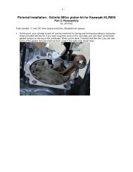
<strong>Pictorial</strong> <strong>Installation</strong> : <strong>Schnitz</strong> <strong>685cc</strong> <strong>piston</strong> <strong>kit</strong> <strong>for</strong> Kawasaki KLR650<br />
Part 1: Disassembly<br />
by: JeremyZ<br />
Note: This pictorial was conducted on a non-Cali<strong>for</strong>nia, US model 2009 KLR650. On Cali<strong>for</strong>nia and<br />
Australian models, there are slight differences, which are pointed out in the manuals. When I refer to<br />
“right” or “left”, I mean as you sit on the bike.<br />
1) Buy the <strong>piston</strong> <strong>kit</strong> and a service manual. I bought both the factory and Clymer<br />
manuals. I compared the manuals <strong>for</strong> the first few steps, and found that I greatly<br />
prefer the Clymer manual. It seems to have been written by a human being<br />
instead of a robot, and warns the would-be mechanic of any pitfalls ahead of<br />
time. new factory gaskets. (head gasket, cam chain tensioner gasket)
2) Remove the side fairings. This photo shows two of the three bolts that must be<br />
removed.<br />
2
Here’s the third bolt. This photo is looking up at the underside of the fairing, next to the<br />
left <strong>for</strong>k tube. (left as you’re sitting on the bike)<br />
3
4<br />
When that last bolt, note that this bolt also holds on the grille which covers the radiator.<br />
The grille has two nubs on the left side (as you look at it in this photo) that fit into holes<br />
in the radiator mounting flange.
5<br />
Repeat the same thing on the other side. The outside bolts are in the same places. The<br />
inside one is a little higher, and really tucked under there:
6<br />
3) Take off the side covers, near below the seat, on each side. In the photo below,<br />
the red circles show the bolt locations that hold on the side cover. The blue circle<br />
shows where the side covers snap in at the bottom. The green circle shows the<br />
bolts that holds the seat down. These locations are the same on the right side of<br />
the bike. After you remove the seat, also disconnect the negative battery<br />
terminal, which is also visible in the photo below. If you don’t, there is a high<br />
probability you will accidentally short it out later.
7<br />
4) The next step is to pull the fuel tank. (See pg. 3-26 in the factory service manual)<br />
Turn the fuel tap to OFF, then remove the two hoses going to it.
8<br />
5) After turning off and disconnecting the petcock, remove the drain hose (green)<br />
and the fuel tank bolts (pink) these are 10mm. Then, lift up a bit and gently slide<br />
the tank backwards off the frame. Put it somewhere it won’t get knocked over. It<br />
will sit on its own without damaging the petcock.
9<br />
6) Next, remove the cover <strong>for</strong> the starter relay by removing the Phillips screw.<br />
7) Then, remove the screws that hold the starter relay bracket to the bike. Notice<br />
that when I remove screws & bolts, I immediately replace them into the holes<br />
they came from.
8) Next, pull the skid plate. There are four screws holding it on, symmetrically<br />
placed on each side, as indicated below.<br />
10
11<br />
9) Time to drain the coolant. First, remove the coolant drain plug from the bottom of<br />
the coolant pump enclosure on the right-hand side of the engine, shown below.<br />
The coolant will start to trickle out. I used my oil pan, but first, I cleaned it by<br />
putting some rubbing alcohol on a paper towel and cleaning it out.
12<br />
10) Once the coolant starts flowing out, go around to the left side of the bike, hold it<br />
vertical, and remove the radiator cap from the radiator. The coolant will come out<br />
like mad after that. When it is done draining, put the bike back down, come<br />
around to the right side of the bike, and lean it towards yourself to get the last few<br />
ounces out.
13<br />
11) Next, drain the coolant from the coolant reservoir tank. You’ll need to take off the<br />
guard <strong>for</strong> it first:
14<br />
12) Now, it’s time to empty the coolant reservoir tank. Take off the overflow hose, by<br />
loosening the spring clip. The four bolts holding it on are in green, and the<br />
overflow hose and spring clip are circled in red. On mine, the top left one had<br />
vibrated itself out and was lost, so when you put this back on later, I suggest<br />
using blue thread locker. Once these are all removed, take off the cap, maneuver<br />
the tank around so you can dump it into the drain pan that contains the rest of the<br />
coolant.
15<br />
13) Next, remove the thermostat housing, and pull the thermostat out of the engine. If<br />
there is an accumulation of rubber particles on the thermostat, there’s probably a<br />
hose somewhere in the cooling system that is coming apart. Replace the bolts in<br />
their holes.
16<br />
14) Time to pull the carburetor. Disconnect the vacuum switch hose from the carb.<br />
Remove the clamps from the air filter housing duct and intake duct by removing<br />
the Phillips screws, rotating them around and working them off. Also, remove the<br />
cable holder screw. Rotate the cables down so they can be pulled out the slot.<br />
The cable holder assembly is now hanging loose. I used a cable tie to tie it up to<br />
another cable tie on the main frame and keep it out of the way. If the cable holder<br />
screw is too tight, don’t pound on it or use an impact driver, or you risk<br />
cracking the carb, which is BIG bucks, <strong>for</strong> such a cheap pot metal thing. In that<br />
case, remove the cables instead, and mark their positions. Since my ’09 is nearly<br />
new, this screw hadn’t frozen up.
17<br />
15) This is about the point where I started bagging and labeling parts. Up to this<br />
point, I could simply put the bolts back in the holes that came out of, and it would<br />
be obvious later. After this photo was taken, I started overlapping the edges of<br />
the bags, so it was obvious in which order the parts had come off.
18<br />
16) Next, remove the overflow hose from the other side (left) of the carb. This one<br />
doesn’t have a clamp; fine with me! All the same, it is on pretty tight. I had to pry<br />
the end of it with a flat-head screwdriver to help work it off.
17) Work the air filter housing duct off the rear of the carb, as such:<br />
19
20<br />
18) Then, push the carb back and pry the intake duct off the front of the carb. Rotate<br />
the carb so you can get to the choke plunger. You may have to temporarily<br />
remove a hose so you can get a 12 mm open-end wrench on the choke plunger.<br />
With this done, remove the carb. from the right side of the bike.<br />
19) As you progress, fill the holes with paper towels to keep junk from getting in<br />
there. I started labeling all the hoses too. Masking tape will work, I only had<br />
painter’s tape on hand.
21<br />
20) Get a 3 mm socket head (“Allen”) wrench, and take the carb over to the gas tank.<br />
Open the gas tank, and loosen the float chamber drain screw to drain the<br />
remaining gas out of the carb and back into your gas tank.<br />
21) Now, to remove the exhaust pipe. Remove the rear brake reservoir cover. It is<br />
held on with two #3 Phillips screws here:
22<br />
22) Get your 6 mm allen wrench and loosen (no need to remove) the exhaust pipe<br />
clamp bolt. It is the lower circle in this pic. Since I don’t have any ball allen<br />
wrenches, I had to also remove the bolt holding on the rear brake reservoir. (no<br />
biggie, upper circle) Loosely replace the screws back through the bracket that<br />
held the cover on, indicated by the arrows. I bagged & labeled the cover. There’s<br />
starting to be a lot of covers & panels laying around…<br />
23) Remove the exhaust pipe bracket bolt:
23<br />
24) Next, remove the exhaust pipe retaining acorn nuts, on the front of the engine. If<br />
they’re corroded or stubborn, first apply a penetrating oil, let it soak in, and work<br />
the nuts back & <strong>for</strong>th a bit to break the corrosion loose. After this step, you can<br />
work the exhaust pipe off.<br />
25) Look at all that soot, and in only 3330 miles! I’m glad I’m doing this, and I’m<br />
hopeful that the <strong>685cc</strong> <strong>kit</strong> will fix this.
24<br />
26) Be<strong>for</strong>e proceeding, I scraped off some of the caked-on soot here, stuffed paper<br />
towels in the exhaust opening, and replaced the acorn nuts back on the studs. By<br />
the way, Clymer recommends a new exhaust gasket when re-assembling. I didn’t<br />
notice this until I was putting my bike back together, and didn’t have it. So I reused<br />
the old one. If it isn’t running right one day, I’ll have to remember this…<br />
Since you’re just taking the bike apart, you have time to order one now.
25<br />
27) Now, remove the fan. Unplug the fan connector. (green circle) It is tight, because<br />
it is sealed with an O-ring. Then, remove the fan mounting bolts. (red circles)
26<br />
28) I tied the fan up and out of the way with a cable tie to the handlebar.<br />
29) Pull the spark plug cap, straight up and off. If you want, this is a good time to<br />
check the gap spacing and cleanliness of the gap. Mine was kind of sooty, but<br />
not too bad.
30) Next, disconnect the coolant temperature sending unit connector. It’s just a<br />
quick-connect. Pull it straight up to get it off.<br />
27
28<br />
31) Disconnect the intake hose from the Clean Air System vacuum switch, (green)<br />
then remove the bolts that hold the vacuum pipe and remove the pipe. (red)<br />
32) Remove the four valve cover bolts:<br />
on the left.<br />
Make a note on the baggie that the shorter ones go
29<br />
33) Remove the left fuel tank rubber mounting pad. Here’s where it came from; just<br />
pull it straight out.<br />
34) Lift up the valve cover, and pull the gasket from the bottom of it. You’ll need that<br />
space to maneuver the valve cover out from under the frame. It is a tight fit.<br />
Looking at the cam lobes, we can tell that the crankshaft is not at top dead center<br />
(TDC) to check the valve clearances. We’d be silly not to, since we’re in here<br />
anyway.
30<br />
35) Now, we need to get the cams crankshaft to TDC. Remove the timing plug (top)<br />
and rotor bolt plug. I put a quarter in the slots, and turned it loose with a regular<br />
old slip-joint pliers. Watch out so you don’t lose either of those O-rings. Then, get<br />
your ratchet and, short extension, and 19 mm socket on the crank bolt.<br />
Make sure the bike is in neutral. Look through the timing hole as you slowly turn<br />
the crank CCW. When the T-mark lines up with the cut-out in the bottom of the<br />
timing hole, check the cam lobes. If the lobes are pointing out from the center of<br />
the cylinder, you’re at TDC. If not, turn the engine over again, CCW, until the T<br />
mark lines up with the cut-out at the bottom of the timing hole. All four cam lobes<br />
should be pointing outward from the cylinder center, like so:
31<br />
36) Now that we have the cams in the right position, we check the valve clearances<br />
with our feeler gauge set. Starting with 0.004”, slide the feeler gauges between<br />
the cam and the shim so slight pressure is needed to get it between. Either it will<br />
fit or not. If it fits, try to get the next bigger one in. If the next bigger one won’t fit,<br />
the thickness of that feeler gauge is your clearance. If the next bigger one will fit,<br />
keep going until one won’t fit. The one be<strong>for</strong>e that is your clearance.<br />
The specs are as follows:<br />
Intake: 0.004 – 0.008” (0.10 – 0.20 mm)<br />
Exhaust: 0.006 – 0.010” (0.15 – 0.25 mm)
32<br />
37) Ideally, we want them to be more toward the top of the spec. Mine were<br />
bordering on too tight. I’m going to order or trade <strong>for</strong> thinner shims tomorrow, and<br />
I should have them by the time we are ready to re-assemble the engine. Write<br />
down the measurements. I recorded mine in the back of my Clymer manual.<br />
Later, when the camshafts are out, we can easily pull the shims to finish up this<br />
data. (i.e. – Which shim thicknesses were on which lifters, so we know which way<br />
to go with regards to shim thicknesses.)<br />
38) Now, let’s pull the cam chain tensioner. It is on the left side of the engine, about<br />
halfway down the cylinder. Loosen the center bolt a bit, but don’t remove it.<br />
(green) Then, remove the top and bottom bolts. (red)<br />
There’s no going back now. Once those mounting bolts are loosened, the cam<br />
chain tensioner must be removed & reset. The manual has more details on this.
33<br />
The manual also recommends getting a new copper gasket <strong>for</strong> this too. Order<br />
one now, along with the exhaust gasket.<br />
39) Now, it is time to pull the camshafts. The first part to this is to stuff clean shop<br />
rags around the cam chain to prevent us from accidentally dropping stuff down in<br />
the<br />
crankcase.<br />
40) Then, loosen the eight camshaft cap bolts, circled above. Do this equally and in<br />
several steps. There are hollow steel dowels underneath that will only allow the<br />
caps to be pulled off from exactly straight up. Do the right intake & exhaust cam<br />
caps first. The left ones are joined by an oil supply pipe, so it is easier to remove<br />
them both at the same time.
34<br />
41) I took a couple of close-ups of the cam caps, so that if I mix them up, I can still<br />
get it back together later:<br />
The exhaust cam has a mechanism on the end of it.
35<br />
42) To remove the upper cam chain guide, double check that the cam chain tunnels<br />
are all stuffed with clean shop towels. Dropping a bolt down in there will induce<br />
cursing. Remove the three bolts holding on the guide. (8 mm) You’ll need an<br />
extension. (I pulled one of the rags out after I got them out <strong>for</strong> photo clarity)<br />
43) By now, the perceptive reader will have noticed that I’m a big fan of using cable<br />
ties to hold stuff out of my way. The cam chain is no exception, and this also<br />
serves to keep it from falling into the crankcase. (edit: string is better, since it<br />
must be removed anyway when the head is taken off.)
36<br />
44) Finally, remove the camshafts from under the cam chain. Your engine top end<br />
should now look like the photo below. Double-check that the cam chain opening<br />
remains properly covered. This photo was taken after I popped the shims off from<br />
the top of the valve lifters. You can see that the edge of each lifters has a cut-out.<br />
The purpose of this is to allow us to stick the edge of a small screwdriver blade or<br />
pick in there to pop the shims loose. I did this, and wrote down which shim<br />
number was on each lifter in the back of my manual. If the cut-out doesn’t line up<br />
with the upper-most part of the lifter, just rotate it with the tip of your screwdriver;<br />
they are loose.
45) Remove the engine mounting bolt (bottom) and engine mounting bracket bolts<br />
(upper) circled below, then remove the brackets.<br />
37
38<br />
46) Remove the banjo bolt (circled) and associated seal washers from the oil pipe.<br />
The seal washers are bronze. When you pull the banjo bolt out of the fitting,<br />
you’ll see why it has a special name; it is a pretty elegant design. (Clymer<br />
recommends getting new gaskets <strong>for</strong> the banjo fitting too)
39<br />
47) Remove the acorn nut from the rear of the cylinder head:<br />
48) Remove the acorn nut and allen bolt from the front of the cylinder head:
40<br />
49) WARNING: Use high-quality, tight-fitting sockets <strong>for</strong> this next step. Craftsman 12-<br />
pt. Sockets will likely strip the heads of the bolts by the time you apply enough<br />
torque to break these loose. (voice of experience) After stripping the head of one<br />
of them, I went out and bought a set of Popular Mechanics Grip-Tite metric<br />
sockets from Sears. ($25) These sockets grab the bolt head by the flats, rather<br />
than the corners, like conventional sockets. Also, on my newish KLR, I needed to<br />
put a pipe on the ratchet handle to get enough torque. Careful not to pull the bike<br />
off the sidestand when you loosen these. They’re ungodly tight.
41<br />
50) Stuff the cam chain tunnel with clean shop rags, so you don’t drop anything down<br />
into the crankcase. Remove the four cylinder head bolts inside the cylinder head.<br />
Here’s where the left ones were.<br />
51) Here’s where the right ones are:
42<br />
52) Use a mallet to tap around the base of the cylinder head to loosen it up. A dead<br />
blow mallet would work, as would a plastic or rubber headed one.<br />
53) When you lift off the cylinder head, watch out that you don’t drop the locating<br />
dowels. (circled) Note all the carbon from the burnt oil. (arrow) Hard to believe<br />
this is a four-stroke and there are only 3300 miles on it. Also, in this shot, the<br />
head gasket is still stuck to the head. Gently chip off any carbon with a<br />
screwdriver.
43<br />
54) Here’s what the top of the <strong>piston</strong> looked like. Not. Cool.<br />
55) Remove the head gasket from the bottom of the cylinder head or the top of the<br />
cylinder. I was able to get a fingernail under it, then gently pry it up with a putty<br />
knife.
44<br />
56) At this point, I tied the cam chain to the shift lever, so I don’t drop it in the<br />
crankcase.<br />
57) Now, it’s time to pull the cylinder. Remove the coolant hose from the front of the<br />
cylinder, by loosening the hose clamp, breaking it loose, and sliding it up the<br />
hose.
45<br />
58) The Clymer manual doesn’t say this, but you’ll need to remove the starter motor<br />
to get good access to the next couple bolts. Remove bolts (1), which hold the<br />
starter motor in place. Then, remove the rubber boot (2) and disconnect the<br />
positive lead from the starter motor. Replace the nut. Then, twist the motor back<br />
and <strong>for</strong>th (3) and pull it out. It is held in place by friction with an O-ring. Lastly,<br />
remove the oil pipe retainer bolt. (4)
46<br />
59) Now, it’s time to remove the cylinder head. The first bolt is under the cam chain<br />
guide. Just pull it up, and take care to note how it goes together.<br />
60) Here’s the bolt:
47<br />
61) Remove the cylinder mounting nut from the rear of the cylinder:<br />
62) Remove the front cylinder mounting nut:
48<br />
63) As be<strong>for</strong>e, tap around the base of the cylinder with your mallet. Gently lift it up.<br />
It’ll be a little snug, because of the friction of the <strong>piston</strong> rings on the cylinder bore.<br />
Also, as be<strong>for</strong>e, there are two locating dowels. Don’t let them drop into the<br />
crankcase. I bagged & labeled mine. Remove the coolant fitting and bolts prior to<br />
shipping out the cylinder <strong>for</strong> boring & honing.<br />
64) Removing the stock base gasket will go easier with gasket remover chemical.<br />
Note that the larger diameter valve cutouts on the <strong>piston</strong> are towards the rear of<br />
the engine.
49<br />
65) Pop the circlips (one on each side) out of the edge of the <strong>piston</strong>. I gently pried<br />
them out using the tip of a small flat head screwdriver where the arrow is<br />
pointing. Once both circlips are removed, you should be able to push out the<br />
<strong>piston</strong> pin with your finger and remove the <strong>piston</strong> assembly from the connecting<br />
rod.<br />
66) Put a clean shop rag in the gaping hole in the top of the crankcase to keep junk<br />
out. What’s left of your engine should look like this:
67) I overlapped my pieces and laid them out in the order in which I remove them.<br />
My workbench wound up looking like this:<br />
50