Dynamic Lifter® Pressure Relief Valve - Singer Valve Inc.
Dynamic Lifter® Pressure Relief Valve - Singer Valve Inc.
Dynamic Lifter® Pressure Relief Valve - Singer Valve Inc.

You also want an ePaper? Increase the reach of your titles
YUMPU automatically turns print PDFs into web optimized ePapers that Google loves.
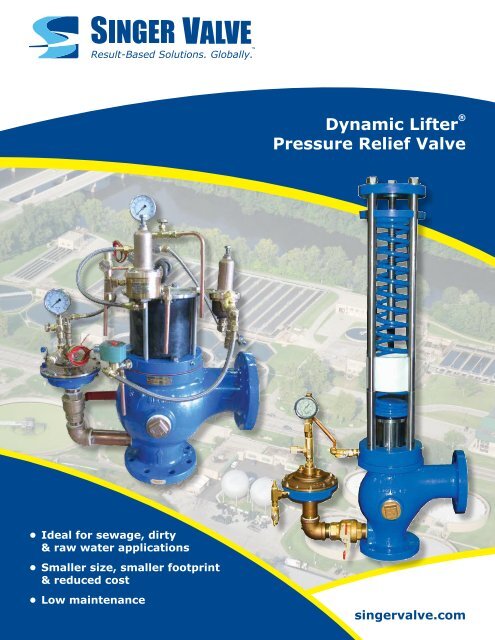
<strong>Dynamic</strong> Lifter ®<br />
<strong>Pressure</strong> <strong>Relief</strong> <strong>Valve</strong><br />
• Ideal for sewage, dirty<br />
& raw water applications<br />
• Smaller size, smaller footprint<br />
& reduced cost<br />
• Low maintenance<br />
singervalve.com
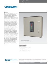
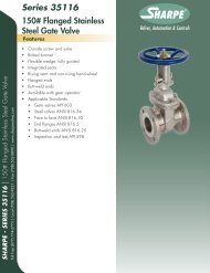
<strong>Dynamic</strong> Lifter ® <strong>Pressure</strong> <strong>Relief</strong> <strong>Valve</strong><br />
Outsmart surges!<br />
The patented <strong>Dynamic</strong> Lifter ® is a direct-acting spring-loaded<br />
relief valve that opens when the inlet pressure exceeds the<br />
set-point. It closes drip-tight when pressure falls below the<br />
set-point. The valve can be serviced easily by applying external<br />
pressure (such as a hand pump) to the test connection, opening<br />
the valve for routine maintenance. Available in two versions:<br />
Spring or Air Operated. The air actuated design is used for<br />
higher relief pressures or when pressurized air actuation is<br />
preferred. Also, because of its smaller profile, it is ideal for<br />
applications with space limitations.<br />
Region of York (Nobleton) installation<br />
Ontario, Canada<br />
Model A-106-DL | <strong>Dynamic</strong> Lifter ® Spring <strong>Pressure</strong> <strong>Relief</strong> <strong>Valve</strong><br />
Traditional design of relief valves for sewage<br />
service has not changed for many years. The<br />
<strong>Singer</strong> <strong>Valve</strong> <strong>Dynamic</strong> Lifter ® is an established and<br />
patented product, designed for minimum (hygienic)<br />
maintenance with assurance that it will open quickly<br />
and consistently when needed.<br />
• Operating oil is separated from sewage by the<br />
chamber and diaphragm isolator (2).<br />
• System pressure is applied to piston (1A) by<br />
mineral oil and isolator (2).<br />
• Piston and closing speed controls operate in clean<br />
non-contaminating environment.<br />
Benefit: Low maintenance.<br />
• System (over) pressure is applied to the opening<br />
piston (1A) throughout the full stroke.<br />
• Allows more relief flow as it does not lose opening<br />
force as the inner valve leaves the seat.<br />
Benefit: Smaller size and reduced cost.<br />
• By closing valve (4), external pressure may be<br />
applied through port (9) and on to piston (1A) by<br />
the mineral oil opening of the <strong>Dynamic</strong> Lifter (1).<br />
• Even a tire pump or compressed air may be used<br />
to open the valve and check the relief setting or<br />
flush stringy material from the seat.<br />
Benefit: Hygienic and minimal time to flush and<br />
test operations.<br />
• Where conventional spring<br />
operated valves allow buildup<br />
of waste-water residue<br />
(dry pack) on the valve’s<br />
downstream and exhaust pipe<br />
to sump, <strong>Singer</strong>’s A106-DL can<br />
easily be opened fully, through<br />
the actuator, to flush out these<br />
unwanted build-ups.<br />
Benefit: Ease of maintenance.<br />
Clients Who Use the <strong>Dynamic</strong> Lifter<br />
• Public Service Commission, Tijuana, Mexico<br />
• Halifax Regional Municipality, Nova Scotia,<br />
Canada<br />
• Hamilton, and Regions of Halton and Peel,<br />
Ontario, Canada<br />
• Borough of Phoenixville, Pennsylvania<br />
A106-DL<br />
• Heat fused, heavy epoxy coating inside and out,<br />
316 stainless steel seat (1C) and stem (1B). The<br />
stem is also oxy-nitride coated to reduce mineral<br />
or debris build-up.<br />
Benefit: Premium materials and coating reduce<br />
maintenance and provide the lowest long-term cost<br />
of ownership.<br />
singervalve.com<br />
2
<strong>Dynamic</strong> Lifter ® <strong>Pressure</strong> <strong>Relief</strong> <strong>Valve</strong><br />
Optional<br />
Component<br />
14<br />
7<br />
Fill<br />
Oil<br />
Factory<br />
Filled<br />
HEADER<br />
9<br />
Option<br />
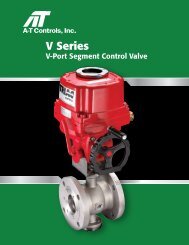
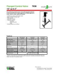
1. Model A106-DL - body<br />
(1A) Piston, (1B) Stem, (1C) Seat<br />
2. Chamber and diaphragm isolator<br />
3. Closing speed control needle valve<br />
4. Isolating valve<br />
5. Oil fill isolating valve<br />
6. <strong>Pressure</strong> gauge<br />
7. Isolating valve<br />
8. Swing check valve<br />
9. Isolating valve – external pressure for<br />
test and flush cycle<br />
10. 3/8" NPT flexible hose<br />
11. Isolating valve<br />
12. (Optional) Field connection by others<br />
13. Model 852B gauge cock<br />
14. Limit Switch (optional)<br />
Sewage Area<br />
Typical Application<br />
Application drawing is applicable to both A-106-DL and A-106-DL-Air.<br />
Check<br />
valves<br />
<strong>Singer</strong> <strong>Valve</strong><br />
<strong>Dynamic</strong> Lifter Spring<br />
<strong>Pressure</strong> <strong>Relief</strong> <strong>Valve</strong><br />
Sewage<br />
pumps<br />
singervalve.com<br />
3
<strong>Dynamic</strong> Lifter ® <strong>Pressure</strong> <strong>Relief</strong> <strong>Valve</strong><br />
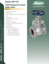
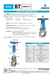
Model A-106-DL-Air | <strong>Dynamic</strong> Lifter ® Air Operated <strong>Pressure</strong> <strong>Relief</strong> <strong>Valve</strong><br />
Model A-106-DL-Air-ET | Surge Anticipating Electronically Timed DL<br />
<strong>Pressure</strong> <strong>Relief</strong> <strong>Valve</strong><br />
A compact sewage relief valve that is suitable for<br />
high pressures, responds very quickly and retains<br />
all the features and benefits of the Spring–Hydraulic<br />
version. It is an attractive solution to what may<br />
be otherwise a difficult application due to higher<br />
pressures or space (height) limitations.<br />
• Operates using separate compressed air supply<br />
• An inexpensive 120 psi (8.3 bar) air compressor<br />
may be used for 200 psi (13.8 bar) or higher relief<br />
pressures by using a large diameter closing piston<br />
(1A).<br />
Benefit: Inexpensive Control Source for large<br />
pressure range.<br />
• Using a chamber and diaphragm isolator (8),<br />
an accurate hydraulic pilot (4) opens reliably and<br />
repeatedly at its set pressure (gauge 5A).<br />
• Full operational (including pilot) check is quickly<br />
and cleanly performed by closing valve (7) and<br />
applying pressure at (2C). For quick flush open<br />
(3B).<br />
Benefit: Operation check of all components with<br />
flushing is quick and sanitary.<br />
10<br />
Compressed Air<br />
3B 5B 100 psi / 6.9 bar -<br />
150 psi / 10.35 bar<br />
4<br />
6 9 2B<br />
11<br />
5A<br />
3A<br />
Mineral<br />
Oil<br />
2D<br />
8<br />
2C<br />
2A<br />
1A<br />
1B<br />
12<br />
14<br />
7 1<br />
Sewage Area<br />
Optional<br />
Components<br />
13<br />
• As an option, two 3-way<br />
solenoids (12, 13) may<br />
be included to force the<br />
valve open on power<br />
failure. A backup control<br />
panel is required to time<br />
the reclosure.<br />
Benefit: The solenoids convert<br />
the relief valve function to a surge<br />
anticipating valve if needed,<br />
particularly if there is a risk of the<br />
system going sub-atmospheric.<br />
Air pressure through solenoid (13)<br />
holds the valve open until closed<br />
by the electrical controls.<br />
A106-DL-ET<br />
• The check valve (9) maintains air in the operating<br />
cylinder (1B) should the air supply fail.<br />
• Provided the air supply is above minimum,<br />
variations in pressure do not affect the valve<br />
operation, which is controlled independently by the<br />
accurate pilot (4).<br />
The main valve (1) is constructed of the same<br />
premium materials as the Hydraulic <strong>Dynamic</strong> Lifter ®<br />
for long life and minimum maintenance.<br />
1. Model A106-DL-Air - body<br />
(1A) Piston, (1B) Cylinder<br />
2A, 2B, 2C, 2D, Isolating <strong>Valve</strong>s<br />
3A, 3B, Needle <strong>Valve</strong><br />
4. <strong>Relief</strong> Pilot: 81-RP<br />
5A, 5B, <strong>Pressure</strong> Gauge<br />
6. Fixed Restriction<br />
7. Isolating <strong>Valve</strong> – Sewage<br />
8. Chamber and Diaphragm Isolator<br />
9. Check <strong>Valve</strong>, J0040A<br />
10. Bleed <strong>Valve</strong><br />
11. Air Supply<br />
12. Optional Solenoid<br />
13. Optional Solenoid<br />
14. Optional Limit Switch Assembly<br />
Note: Alternate orientation option available—consult with factory.<br />
singervalve.com<br />
4
<strong>Dynamic</strong> Lifter ® <strong>Pressure</strong> <strong>Relief</strong> <strong>Valve</strong><br />
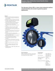
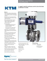
<strong>Dynamic</strong> Lifter Sizing Graph Curve: 3 in / 80 mm - 8 in / 200 mm<br />
Conventional relief valves for sewage are typically sized “larger” than a <strong>Singer</strong> <strong>Valve</strong> <strong>Dynamic</strong> Lifter due to opening forces being lost<br />
as the inner valve leaves the seat.<br />
L/S<br />
1262<br />
1000<br />
900<br />
USGPM<br />
20000<br />
8"<br />
(200 mm)<br />
800<br />
700<br />
600<br />
10000<br />
9000<br />
6"<br />
(150 mm)<br />
500<br />
8000<br />
7000<br />
400<br />
6000<br />
300<br />
5000<br />
4000<br />
4"<br />
(100 mm)<br />
Q- Pipeline Maximum Flow<br />
Q-Pipeline Maximum Flow<br />
200<br />
100<br />
90<br />
80<br />
70<br />
60<br />
50<br />
40<br />
30<br />
3000<br />
2000<br />
1000<br />
900<br />
800<br />
700<br />
600<br />
500<br />
3"<br />
(80 mm)<br />
<strong>Valve</strong> Size Selection<br />
<strong>Valve</strong> Size Selection<br />
400<br />
20<br />
300<br />
200<br />
10<br />
6.3<br />
100<br />
10 20 30 40 50 60 70 80 90 100<br />
200 Psi<br />
1 2<br />
3 4 5 6 7 8 9 10 13.8 bar<br />
∆P - Minimum pressure drop across dynamic lifter.<br />
Consult <strong>Singer</strong> <strong>Valve</strong> for<br />
higher pressures.<br />
Examples of valve size selection:<br />
1) <strong>Relief</strong> setting 80 psi / 5.5 bar - discharge to atmosphere: Max. flow in main pipeline 1,200 USGPM / 75.7 l/s - Find intersect of<br />
P - Mimumum <strong>Pressure</strong> Drop Across <strong>Dynamic</strong> Lifter<br />
80 psi / 5.5 bar ∆P and 1200 USGPM / 75.7 l/s flow. Select next larger size <strong>Dynamic</strong> Lifter, for example, 3 in / 80 mm size.<br />
2) <strong>Relief</strong> setting 55 psi / 3.8 bar - discharge 20 psi / 1.38 bar back pressure: Max. flow in main pipeline 4,000 USGPM / 252.4 l/s<br />
Find intersect of 55 psi – 20 = 35 psi / 2.4 bar ∆P and 4000 USGPM / 252.4 l/s flow. Select next larger size <strong>Dynamic</strong> Lifter,<br />
for example, 6 in / 150 mm size.<br />
Note:<br />
• If the discharge was to atmosphere, ∆P = 55 psi / 3.8 bar and 4 in / 100 mm size would be selected.<br />
• This graph is based on current practice for standard applications. It is intended to be a guide only and no selection guarantee is<br />
implied or intended.<br />
singervalve.com<br />
5
<strong>Dynamic</strong> Lifter ® <strong>Pressure</strong> <strong>Relief</strong> <strong>Valve</strong><br />
<strong>Valve</strong> Sizing and Measurements<br />
A106-DL ANSI DATA (US UNITS) SINGLE SPRING STACK DOUBLE SPRING STACK<br />
Size 3 in 4 in 6 in 8 in 6 in 8 in<br />
<strong>Relief</strong> Settings (psi)<br />
Min Max Min Max Min Max Min Max Min Max Min Max<br />
Spring Specific Ranges<br />
25 90 20 65 15 30 10 15 40 90 30 50<br />
70 200 60 145 25 60 15 30 90 160 50 80<br />
Other ranges available, consult with <strong>Singer</strong> <strong>Valve</strong><br />
Lift / Opening 2 in 2 in 2 1/2 in 3 in 2 1/2 in 3 in<br />
Dimension A 9 in 10 in 11.5 in 14 in 11.5 in 14 in<br />
Dimension B 38.5 in 39.5 in 43.75 in 45.75 in 25.25 in 26.75 in<br />
Dimension C 30.5 in 30.5 in 32 in 32 in 32 in 32 in<br />
Dimension D 4.75 in 5.75 in 7.5 in 10 in 15.25 in 18.25 in<br />
A106-DL ANSI DATA (METRIC UNITS) SINGLE SPRING STACK DOUBLE SPRING STACK<br />
Size 80 mm 100 mm 150 mm 200 mm 150 mm 200 mm<br />
<strong>Relief</strong> Settings (bar)<br />
Min Max Min Max Min Max Min Max Min Max Min Max<br />
Spring Specific Ranges<br />
1.72 6.21 1.38 4.48 1.03 2.07 0.69 1.03 2.76 6.21 2.07 3.45<br />
4.83 13.79 4.14 10.00 1.72 4.14 1.03 2.07 6.21 11.03 3.45 5.52<br />
Other ranges available, consult with <strong>Singer</strong> <strong>Valve</strong><br />
Lift / Opening 50 mm 50 mm 64 mm 76 mm 64 mm 76 mm<br />
Dimension A 229 mm 254 mm 292 mm 356 mm 292 mm 356 mm<br />
Dimension B 978 mm 1004 mm 1112 mm 1162 mm 641 mm 680 mm<br />
Dimension C 775 mm 775 mm 813 mm 813 mm 813 mm 813 mm<br />
Dimension D 121 mm 146 mm 191 mm 254 mm 387 mm 464 mm<br />
A106-DL ANSI DATA (US UNITS)<br />
AIR OPERATED<br />
Size 3 in 4 in 6 in 8 in<br />
<strong>Relief</strong> Settings (psi)<br />
<strong>Pressure</strong> Ranges<br />
Options Available up to 200 psi, consult with <strong>Singer</strong> <strong>Valve</strong><br />
Lift / Opening 2 in 2 in 2 1/2 in 3 in<br />
Dimension A 9 in 10 in 11.5 in 14 in<br />
Dimension B* 22.5 in 23.5 in 25.5 in 28.88 in<br />
Dimension C 30.5 in 30.5 in 32 in 32 in<br />
Dimension D 4.75 in 5.75 in 7.5 in 10 in<br />
A106-DL ANSI DATA (METRIC UNITS)<br />
AIR OPERATED<br />
Size 80 mm 100 mm 150 mm 200 mm<br />
<strong>Relief</strong> Settings (bar)<br />
<strong>Pressure</strong> Ranges<br />
Options Available up to 13.8 bar, consult with <strong>Singer</strong> <strong>Valve</strong><br />
Lift / Opening 50 mm 50 mm 64 mm 76 mm<br />
Dimension A 229 mm 254 mm 292 mm 356 mm<br />
Dimension B* 572 mm 597 mm 648 mm 734 mm<br />
Dimension C 775 mm 775 mm 813 mm 813 mm<br />
Dimension D 121 mm 146 mm 191 mm 254 mm<br />
A Variety of Models to Choose From<br />
Pneumatic<br />
operational ranges<br />
up to 200 psi / 13.8 bar.<br />
Consult your local<br />
representative, or factory,<br />
for higher pressures.<br />
This area allows for<br />
pilot system components<br />
'B' DIM<br />
'B' DIM<br />
'B' DIM<br />
'D' DIM<br />
(DOUBLE)<br />
'D' DIM<br />
(SINGLE)<br />
'A DIM<br />
'A' DIM<br />
'A' DIM<br />
'C' DIM<br />
(CONFIRM LOCATION)<br />
'A' DIM<br />
Pneumatic<br />
(All <strong>Pressure</strong> Ranges<br />
Plus Excessive <strong>Pressure</strong>s)<br />
A' DIM<br />
Single Spring Stack<br />
(Lower <strong>Pressure</strong> Ranges)<br />
'D' DIM<br />
Double Spring Stack<br />
(Higher <strong>Pressure</strong> Ranges)<br />
Assembly Clearance<br />
(Applicable To All Models)<br />
singervalve.com<br />
6
<strong>Dynamic</strong> Lifter ® <strong>Pressure</strong> <strong>Relief</strong> <strong>Valve</strong><br />
Specifications<br />
A106-DL Spring<br />
The sewage pressure relief valve shall be direct<br />
acting spring loaded angle style and shall open fully<br />
and quickly when the system pressure exceeds the<br />
valve set point.<br />
The closing speed shall be adjustable. The valve is to<br />
close drip tight when pressure is below the set point.<br />
A separation chamber and diaphragm shall transmit<br />
pressure to an opening piston to assist the<br />
opening forces.<br />
Provision shall be made to readily connect external<br />
pressure and test cycle the valve opening to confirm<br />
the opening and closing, and the relief pressure. It<br />
will flush out materials that may be clogging the valve<br />
flow or causing a sticking stem or preventing drip<br />
tight closing. It shall assist in flushing dry pack on<br />
the downstream side of the valve. The maintenance<br />
test is to be clean and sanitary.<br />
The construction is to be suitable for long life when<br />
used in a raw sewage environment.<br />
Prior to shipping the standard factory test shall include<br />
cycling at full stroke at the requested relief setting,<br />
drip tight leakage test and over pressure shell test.<br />
The Sewage <strong>Relief</strong> <strong>Valve</strong> shall be ANSI Class 150 / PN<br />
16 flanges size __ in / __ mm. Spring range __ psi /<br />
__ bar to __ psi / __ bar factory set at __ psi / bar.<br />
The valve shall have all the features and functions of<br />
the <strong>Singer</strong> Model A106-DL or approved equal.<br />
A106-DL-Air<br />
The sewage pressure relief valve shall be compressed<br />
air actuated, angle style and open fully and quickly<br />
when the system pressure exceeds the valve set<br />
point. The closing speed is to be adjustable. The<br />
valve shall close drip tight when system pressure is<br />
below the valve set point.<br />
A separation chamber and diaphragm shall transmit<br />
the system pressure (using mineral oil) to an<br />
accurate but easily adjustable hydraulic pilot.<br />
Compressed air will be supplied by others at a<br />
pressure exceeding 100 psi / 6.9 bar to actuate a<br />
piston to close the valve.<br />
Sewage system pressure above the set point shall<br />
cause the pilot to release air from the chamber that<br />
holds the sewage relief valve closed.<br />
For a complete maintenance check it shall be possible<br />
to apply pressure to the separation chamber and<br />
check the opening pressure of the hydraulic pilot<br />
and the main valve.<br />
A separate means of lowering the air pressure in<br />
the main chamber is to be provided for a quick<br />
flush cycle. It shall assist in flushing dry pack on<br />
the downstream side of the valve. The maintenance<br />
testing is to be clean and sanitary.<br />
The construction is to be suitable for long life when<br />
used in a raw sewage environment.<br />
Prior to shipping the standard factory tests shall<br />
include cycling at full stroke at the requested relief<br />
setting, drip tight leakage test and over pressure<br />
shell test of both the valve and air chamber.<br />
The Sewage <strong>Relief</strong> <strong>Valve</strong> shall be ANSI Class 150<br />
(PN 16) flanges, Size ___ in / ___ mm. Operating<br />
relief range ___ psi / ___ bar to ___ psi / ___ bar<br />
with air supply between 100 psi / 7 bar and 150 psi<br />
/ 10.4 bar. Factory relief setting ___ psi / ___ bar.<br />
The valve shall have all the features and functions<br />
of the <strong>Singer</strong> Model A106-DL-Air or approved equal.<br />
Region of Peel installation - Ontario, Canada<br />
singervalve.com<br />
7
Canada Head Office<br />
12850 – 87th Avenue<br />
Surrey, BC V3W 3H9<br />
Canada<br />
Tel: (604) 594 5404<br />
Fax: (604) 594 8845<br />
Toll Free Fax (Canada & USA):<br />
1 800 663 7266<br />
singer@singervalve.com<br />
USA Office<br />
Mailing Address<br />
<strong>Singer</strong> <strong>Valve</strong> LLC<br />
PO Box 668588<br />
Charlotte, NC 28266<br />
Shipping Address<br />
1873 Scott Futrell Drive<br />
Charlotte, NC 28208<br />
Tel: (704) 391 5785<br />
Fax: (704) 391 5768<br />
Toll Free (USA):<br />
1 888 764 7858<br />
mark@singervalve.com<br />
United Arab Emirates Office<br />
<strong>Singer</strong> <strong>Valve</strong> Middle East FZE<br />
PO Box 121326<br />
SAIF Free Zone<br />
Q3 – Unit 94<br />
Sharjah International Airport<br />
FREE ZONE<br />
Sharjah, UAE<br />
Tel: +971 6 557 8116<br />
Fax: +971 6 557 8117<br />
canadian@singervalve.com<br />
Malaysia Office<br />
SVM Water Controls Sdn. Bhd.<br />
No 6, Jalan MJ 4, Medan Maju Jaya,<br />
Batu 7, Jalan Kelang Lama<br />
46200 Petaling Jaya<br />
Selangor Darul Ehsan, Malaysia<br />
Tel: 603 7784 4043 / 7784 4044<br />
Fax: 603 7781 8312<br />
svmwc@tm.net.my<br />
China Office<br />
<strong>Singer</strong> <strong>Valve</strong> (Taicang) Company Ltd.<br />
No.88 East Dalian Road,<br />
Taicang, Jiangsu, China<br />
Tel: 86 512 5320 6188<br />
Fax: 86 512 5320 6099<br />
lijun@singervalve.com<br />
RCM-2013<br />
singervalve.com