MFJ-434B Instruction Manual Voice Keyer 1 ... - SK6AW
MFJ-434B Instruction Manual Voice Keyer 1 ... - SK6AW
MFJ-434B Instruction Manual Voice Keyer 1 ... - SK6AW

Create successful ePaper yourself
Turn your PDF publications into a flip-book with our unique Google optimized e-Paper software.
<strong>MFJ</strong>-<strong>434B</strong> <strong>Instruction</strong> <strong>Manual</strong><br />
<strong>Voice</strong> <strong>Keyer</strong><br />
INTRODUCTION<br />
The <strong>MFJ</strong>-<strong>434B</strong> was designed by contesters and optimized to perform under the toughest<br />
operating conditions. You don't need to be a contest superstar to appreciate what the <strong>MFJ</strong>-<strong>434B</strong><br />
can do. Even casual operators will discover the <strong>MFJ</strong>-<strong>434B</strong> is packed with user-friendly features<br />
that make operating, both in and out of contests, more enjoyable and fun. Set it up, and you'll be<br />
amazed how quickly it becomes part of your operating routine.<br />
Before you begin, please read this manual thoroughly. It contains important information you'll<br />
need to know before attempting to interface the <strong>MFJ</strong>-<strong>434B</strong> with your transceiver. We'll start<br />
with a brief introduction to the special features that make your <strong>Voice</strong> <strong>Keyer</strong> an important<br />
addition to any station, and an absolute necessity for any serious contest station:<br />
Easy Selection: Large soft-touch switches select up to five pre-recorded messages.<br />
Big Memory: Up to 75 seconds accumulated storage.<br />
Dual Front Panel Microphone Connectors: Connect an 8 pin round or RJ-45 modular<br />
connector equipped microphone.<br />
Endless-Loop Timer: Convenient front panel controls adjust repeat-message interval of 0.5-50<br />
seconds or 5-500 seconds. Timing cycle begins at the end of your message.<br />
Built-in Mic Interface: Internal jumpers for connection to transceivers including Yaesu, Icom,<br />
and Kenwood/Alinco radios.<br />
Automatic Message Stop: Microphone PTT switch automatically halts outgoing messages.<br />
<strong>Manual</strong> Message Stop: Prominent red STOP button halts outgoing messages.<br />
Built-in Amplifier/Speaker: Monitors outgoing messages and previews stored messages.<br />
Two Microphone Sources: Record from your station microphone for seamless audio<br />
continuity, or use the built-in electret microphone.<br />
External Microphone Power Select: Adjust internal jumpers to select the proper microphone<br />
power level appropriate for your external microphone.<br />
Off-Air Recording: Capture signals from your receiver's audio jack for review or replay.<br />
RFI Proof Circuitry: Extensive suppression and line isolation virtually eliminates RF feedback,<br />
hum, and distortion. Isolation transformer prevents mic circuit ground loops.<br />
Dual-Level Gain: Spreads adjustment range for more precise mic gain settings.<br />
Transparent Audio: <strong>Keyer</strong> electronics won't color your station's normal audio quality.<br />
User-Friendly Panel: Intuitive controls for easy operation under pressure.<br />
External Control: Fully buffered TTL or CMOS level control lines available at rear panel for<br />
external PC or remote control interface. Works with popular logging programs like CT or NA.<br />
Power Flexibility: Power from external filtered 9-15 Vdc external source, or power temporarily<br />
with internal 9V battery.<br />
Rugged Construction: Tough all aluminum cabinet and surface mount construction means DXpedition<br />
survivability, RF immunity, and years of reliable operation.<br />
1
<strong>MFJ</strong>-<strong>434B</strong> <strong>Instruction</strong> <strong>Manual</strong><br />
<strong>Voice</strong> <strong>Keyer</strong><br />
Once again, this manual contains important technical information and operating instructions<br />
you'll need to know before using your keyer. Please read it thoroughly, and enjoy operating to<br />
the fullest!<br />
POWERING YOUR <strong>MFJ</strong>-<strong>434B</strong><br />
Important Note: We recommend turning your radio on before powering up the voice keyer.<br />
When some transceivers are turned off, the PTT line may be held low. This might cause the<br />
keyer to boot up improperly and enter the self-test mode.<br />
External Power: Use any well filtered power source capable of supplying 9-15 Vdc @100 mA<br />
(minimum operating voltge is 8 Vdc under full load, sources exceeding 16 Vdc may permanently<br />
damage this product). The keyer's external power jack accepts a standard 2.1mm coaxial power<br />
plug (spares are available from Radio Shack). The power plug's center pin must be positive (+)<br />
and ground-isolated. The outer shell is negative (-) and may be grounded or floated at the<br />
supply. When connecting to a high current (more than one ampere) supply, we strongly<br />
recommend fuse protecting both positive and negative supply leads with ½ ampere to 1 ampere<br />
fast-blow fuses.<br />
-<br />
+<br />
1-A<br />
1-A<br />
-<br />
+<br />
Power Supply<br />
WARNING: Never insert the power plug with power applied—an accidental short from<br />
(+) to chassis ground may result. Also, never allow keyer supply voltage to exceed 16<br />
Vdc. Connections to high current power sources must be fuse protected!<br />
<strong>MFJ</strong>-1312B Power Supply: The <strong>MFJ</strong>-1312B wall adapter is also suitable for powering your<br />
voice keyer. It comes with a 2.1mm power plug pre-installed, and is available directly from <strong>MFJ</strong><br />
or through your local <strong>MFJ</strong> dealer.<br />
Internal Power: Use any fresh 9-volt battery for this application. Because current drain is<br />
relatively high (15 mA on idle and 65 mA on transmit), battery life is typically quite short.<br />
Continuous or prolonged operation on internal battery power is not recommended.<br />
Important Note: <strong>MFJ</strong> does not recommend powering your unit with a 9-volt battery unless a<br />
suitable external supply is unavailable. To install the internal 9-volt battery, remove the keyer's<br />
cover and locate the battery snap inside. Note the plastic insulating sleeve covering the snap<br />
terminals—this sleeve prevents the contacts from shorting to the case or other components. Slip<br />
the sleeve down onto the wires so it won't become misplaced, and install the battery. Mount the<br />
battery in its retainer on the back panel.<br />
2
<strong>MFJ</strong>-<strong>434B</strong> <strong>Instruction</strong> <strong>Manual</strong><br />
<strong>Voice</strong> <strong>Keyer</strong><br />
IMPORTANT WARNING: Remove the 9-volt battery when storing the keyer for extended<br />
periods. Remember to reinstall the insulating sleeve on the snap clip.<br />
CONNECTING AND OPERATING THE <strong>MFJ</strong>-<strong>434B</strong><br />
Front Panel:<br />
STOP MSG 1 MSG 2 MSG 3 MSG 4 MSG 5<br />
MESSAGES<br />
EXTERNAL<br />
MIC.<br />
INTERNAL<br />
MIC.<br />
<strong>MFJ</strong> <strong>Voice</strong> <strong>Keyer</strong><br />
INT. ON RECORD<br />
ON<br />
X10<br />
<strong>MFJ</strong> -<strong>434B</strong><br />
EXT.<br />
MIC<br />
OFF<br />
XMIT<br />
REC<br />
PLAY<br />
PLAY<br />
VOLUME<br />
OFF<br />
POWER<br />
REPEAT<br />
DELAY<br />
X1<br />
External Mic Jacks<br />
Internal Mic<br />
Mic Int./Ext.<br />
Xmit On/Off<br />
Record (LED)<br />
Record/Play<br />
Play LED<br />
Volume<br />
Power On/Off<br />
Repeat Delay<br />
X1/X10<br />
Stop<br />
Messages<br />
Plugs for 8 pin round or modular microphone connectors<br />
Built-in electret microphone location<br />
Selects internal (in), or external (out) microphone<br />
Disables transmitter PTT line when reviewing messages<br />
Illuminates in record mode, flashes during recording (red)<br />
Selects record mode (in), or play mode (out)<br />
Illuminates when selector is in play mode (green)<br />
Controls volume of monitor speaker (and audio out jack)<br />
Main power switch--on (in), off (out)<br />
Varies message-repeat interval (0.5-50 secs or 5-500 secs)<br />
Multiplies message-repeat interval by x1 (out) or x10 (in)<br />
Halts message, cancels endless-loop function<br />
Selects message slots 1-5 and starts record or playback<br />
3
<strong>MFJ</strong>-<strong>434B</strong> <strong>Instruction</strong> <strong>Manual</strong><br />
<strong>Voice</strong> <strong>Keyer</strong><br />
Rear Panel:<br />
<strong>MFJ</strong> ENTERPRISES, INC.<br />
STARKVILLE, MS USA<br />
POWER<br />
12VDC<br />
AUDIO<br />
OUT<br />
OUTPUT<br />
LEVEL<br />
CONTROL<br />
AUDIO<br />
IN<br />
REMOTE<br />
STOP<br />
MSG1<br />
MSG2<br />
MSG3<br />
MSG4<br />
MSG5<br />
/XMIT<br />
GND<br />
TO<br />
RADIO<br />
MIC.<br />
- +<br />
Power<br />
Audio Out<br />
Output Level Control<br />
Audio In<br />
Remote Port<br />
To Radio Mic<br />
Ground<br />
Requires 9-16 Vdc @ 100mA<br />
Monitor audio output, ~500 mW max<br />
Adjusts microphone output level to radio<br />
600 Ohm input jack for recording external signals<br />
Remote access to messages and transmit busy lines<br />
Audio/PTT (RJ-45) output for radio's microphone input<br />
Ground terminal to station's ground buss<br />
Microphone Connections<br />
IMPORTANT WARNING: Never connect more than one microphone at once to the the<br />
<strong>MFJ</strong>-<strong>434B</strong>. Damage may occur to the voice keyer or other connected equipment.<br />
The <strong>MFJ</strong>-<strong>434B</strong> comes with a standard 8 pin round microphone connector and a RJ-45 modular<br />
connector located on the front panel. These are the same types used by most transceiver<br />
manufacturers. Since manufacturers wire these 8 pin connectors differently, the <strong>MFJ</strong>-<strong>434B</strong><br />
provides a convenient jumper interface to program its connectors for use with different<br />
transceivers. This feature eliminates the need for re-wiring jacks or adding adapter cables. At<br />
the <strong>MFJ</strong> factory, the interface is set for Yaesu transceivers with modular microphone connectors<br />
(FT-817, FT-857, FT-897). If you operate one of these Yaesu transceivers, you may disregard<br />
this section and use your keyer without resetting the interface jumpers. Jumper configurations<br />
for other Yaesu radios are also located in the appendix. If you use a radio made by a different<br />
manufacturer, or different connector refer to the section below.<br />
An internal jumper (J6) selects external microphone voltage. Some microphones require<br />
external voltage to operate. This jumper supplies 0, 1.5, 5, or 8 volts.<br />
4
<strong>MFJ</strong>-<strong>434B</strong> <strong>Instruction</strong> <strong>Manual</strong><br />
<strong>Voice</strong> <strong>Keyer</strong><br />
IMPORTANT WARNING: The <strong>MFJ</strong>-<strong>434B</strong>'s internal jumpers are factory set for<br />
compatibility with Yaesu transceivers (FT-817, FT-857, FT-897) using conventional<br />
dynamic or crystal microphones. When using Icom or Kenwood/Alinco products,<br />
internal jumpers must be reset for the correct manufacturer and microphone voltage.<br />
Microphone Jumper Configuration (Icom, Kenwood, Yaesu)<br />
1. Disconnect any 12VDC source from the <strong>MFJ</strong>-<strong>434B</strong>.<br />
2. Next remove the screws from the sides and top of the voice keyer enclosure. Remove the<br />
cover, being carful not to stress the monitor speaker wires.<br />
3. Use Appendix A at the end of this manual to locate the jumper configuration specific to<br />
your Icom, Kenwood, or Yaesu radio. If your radio is not included in the appendix use<br />
the section below titled Microphone Jumper Configurations (Other Radios).<br />
4. JMP2-9: On the left side of the circuit board, locate the set of headers JMP2-9. There<br />
are 8 possible configurations on each row of jumpers 2-9. See the jumper diagram below.<br />
JMP 9<br />
JMP 8<br />
JMP 7<br />
JMP 6<br />
JMP 5<br />
JMP 4<br />
JMP 3<br />
JMP 2<br />
1 2 3 4 5 6 7 8<br />
Mic<br />
Mic Gnd<br />
PTT<br />
PTT Gnd<br />
Direct<br />
Mic<br />
Mic Gnd<br />
5. Remove the jumpers on JMP2-9 ONLY.<br />
6. Replace the jumpers on JMP2-9 using the diagram specific to your radio located in the<br />
Appendix of this manual. If your radio is not listed use the following section for<br />
determining the jumper settings for other radios.<br />
7. Replace the cover and screws when you have completed the configuration.<br />
PTT<br />
Microphone Jumper Configuration (Other Radios)<br />
1. If your radio is not included in the appendix, the <strong>MFJ</strong>-<strong>434B</strong> can be configured by<br />
obtaining a copy of the wiring diagram specific to your radio microphone.<br />
2. Use the microphone wiring diagram to determine which microphone pins are used for<br />
PTT, PTT Gnd, Mic, Mic Gnd. The front panel view of the microphone connectors<br />
below can be used to determine how the pins will need to be configured.<br />
5
<strong>MFJ</strong>-<strong>434B</strong> <strong>Instruction</strong> <strong>Manual</strong><br />
<strong>Voice</strong> <strong>Keyer</strong><br />
Front Panel View<br />
2<br />
1<br />
8<br />
7<br />
6<br />
3<br />
4<br />
5<br />
87654321<br />
3. JMP4 and JMP9 (Mic): Place jmp 4 and jmp 9 on the corresponding pin number<br />
required by your microphone. This pin number can be determined from the front panel<br />
view above. For example if your radio has Mic input on pin 1 a jumper will be placed on<br />
jmp9 pin 1 and jmp4 pin 1.<br />
4. JMP3 and JMP8 (Mic Gnd): Place jmp 3 and jmp 8 on the pin number required by<br />
your microphone. This pin number can be determined from the front panel view above.<br />
For example if your radio has Mic Gnd on pin 7 a jumper will be placed on jmp3 pin 7<br />
and jmp8 pin 7.<br />
5. JMP2 and JMP7 (PTT): Place jmp 2 and jmp 7 on the pin number required by your<br />
microphone. This pin number can be determined from the front panel view above. For<br />
example if your radio has Mic Gnd on pin 5 a jumper will be placed on jmp2 pin 5 and<br />
jmp7 pin 5.<br />
6. JMP5 and JMP6 (PTT GND): This is often refered to as Ground in some radio<br />
manuals. Place jmp 5 and jmp 6 on the pin number required by your microphone<br />
configuration. This pin number can be determined from the front panel view above. For<br />
example if your radio has PTT Grnd on pin 6 a jumper will be placed on jmp5 pin 6 and<br />
jmp6 pin 6.<br />
7. JMP5 (Direct): Place jumpers on jmp5 (direct) on remaining lines not configured above.<br />
These pins will control up/dn, +VDC, squelch, AF, and other functions commonly found<br />
on transceivers. By placing a jumper on jmp5 the <strong>MFJ</strong>-<strong>434B</strong> circuit is by-passed on the<br />
corresponding pins.<br />
8. JMP6 (Mic Voltage): There are four jumper pins near the front of the circuit board(to<br />
the rear of the green LED), labeled JMP6 with 8V, 5V, 1.5V, and 0V markings. This<br />
jumper is normally set at 0V, which is compatible with Yaesu and other standard<br />
dynamic and crystal microphones that do not require external voltage. If you are using a<br />
microphone that does require external voltage, or if your microphone does not record to<br />
the voice keyer but works normally when connected to the voice keyer, consult the<br />
specifications for your microphone. Place the jumpers in the setting that most closely<br />
matches the voltage specified by your microphone manufacturer.<br />
6
<strong>MFJ</strong>-<strong>434B</strong> <strong>Instruction</strong> <strong>Manual</strong><br />
<strong>Voice</strong> <strong>Keyer</strong><br />
IMPORTANT WARNING: Do not inadvertently change the jumper on HD1. This jumper is<br />
set on pins 7-8 and should not be moved.<br />
Other Internal Adjustments<br />
Please note two other important internal settings while the cover is off and the pc board visible:<br />
1. Dual Gain Control, R29: This trimpot, located next to the audio isolation transformer,<br />
sets the overall adjustment range of the Output Level Control located on the rear panel.<br />
If you find the back panel gain control must be adjusted to an extreme setting (high or<br />
low) to provide the correct levels to your radio, you may reset R29 to bring the Output<br />
Level Control back into its center range.<br />
2. PTT Automatic Override, JMP1: This jumper plug enables the Automatic Override<br />
feature that stops outgoing messages whenever the PTT switch is pressed. When the plug<br />
is removed, the automatic override function is disabled.<br />
Audio Lines<br />
Audio In: This 3.5mm jack accepts audio signals from a receiver or other low impedance<br />
monaural source for recording. Maximum input level is 0 dBm at 600 Ohms (2 Vpp), and the<br />
minimum usable level is –23 dBm into 600 Ohms (0.15 Vpp). Inserting a plug automatically<br />
disconnects the keyer's internal electret mic. Both jack terminals float with respect to ground to<br />
permit connecting balanced or unbalanced sources. If you experience station microphone hum<br />
with an external audio source plugged in, install a 600 Ohm 1:1 audio isolation transformer in<br />
the external audio line (RadioShack RS273-1374). All audio lines, balanced or unbalanced,<br />
should be grounded at one end only.<br />
Audio 680<br />
Omit for Hi-Z source<br />
Stereo Plug<br />
Mono Plug<br />
Audio<br />
Tip Ring Sleeve Tip Sleeve<br />
Audio<br />
IMPORTANT WARNING: Never exceed 3 Vdc or 3 Vpp input on the “Audio In” jack. If<br />
recorded audio is distorted, either reduce the external audio level control or add external<br />
attenuation to reduce level. When using stereo plugs, connect the ring terminal to the<br />
sleeve for 600-Ohm lines, or leave open for hi-Z audio sources.<br />
Audio Out: This 3.5mm jack provides a low impedance monaural output signal from the<br />
keyer's monitor amplifier, disconnecting the internal speaker when a plug is inserted. Output is<br />
unbalanced, and the monitor amplifier delivers a maximum undistorted signal level of<br />
approximately 4Vpp into 4 ohms (or about 500 mW RMS). The jack's tip lead is "hot" and the<br />
sleeve is connected to both signal and chassis ground. When using stereo plugs, do not wire to<br />
the ring terminal (see input jack diagram above). Note that stereo headphones will not function<br />
properly when plugged into this jack.<br />
Remote Port Connections<br />
7
<strong>MFJ</strong>-<strong>434B</strong> <strong>Instruction</strong> <strong>Manual</strong><br />
<strong>Voice</strong> <strong>Keyer</strong><br />
Remote message control lines are provided at the back panel via a male 8-pin IDC plug. This<br />
provides individual access to all five memory lines (MSG1-MSG5) plus the stop message line<br />
(Stop). All lines are isolated by a buffer, and are CMOS and TTL level compatible.<br />
A special output line provides 12 Vdc at low current when the voice keyer is not transmitting.<br />
This line goes logic low when the keyer transmits (Xmit), and can sink more than 20 mA.<br />
Another pin provides a control voltage ground (Gnd), for the control system return path.<br />
These lines are clearly labeled on the back panel for your convenience. The Remote Port IDC<br />
connector may be used to add a remote control box or to provide an interface point for PC driven<br />
message activation. <strong>Instruction</strong>s for constructing a simple remote control switch box and an<br />
external PC interface are provided later in the manual.<br />
Initial Setup<br />
Before powering up your voice keyer, double-check all connections to your transceiver,<br />
microphone, etc. Be especially certain the power source is wired properly and delivering 9-15<br />
Vdc with the center pin positive, and that the supply can handle at least 100 mA. If the supply is<br />
larger than 1 ampere, be sure you fuse the positive and negative lines. Pre-set your keyer's<br />
controls as follows:<br />
Mic Int./Ext: Set as needed--Int for built-in mic or Ext for station's PTT mic.<br />
Xmit: Off (out).<br />
Rec/Play: Play (out).<br />
Volume: 10 o'clock position.<br />
Power: Off (out). Remember to power your transceiver before turning on the keyer.<br />
Repeat Delay: Fully counter-clockwise (CW) for minimum delay.<br />
X10/X1: X1 (out).<br />
Recording A Message<br />
1. Press POWER to ON: The green Play LED should illuminate.<br />
2. Press REC/PLAY switch to REC: The red Rec LED should illuminate and the green Play<br />
LED should extinguish.<br />
3. Choose Audio Source: Audio is available for recording from three sources--the internal mic,<br />
external station mic, and line level Audio In jack. Select as follows:<br />
A. Built-In Electret Mic: Set Mic switch to Int and speak normally about one foot away<br />
from the front panel. Don't crowd the mic element, or distortion may result. Note that<br />
installing a plug into the Audio In jack disables the electret mic. Remove any plug<br />
connected to the Audio In jack before attempting to use the internal mic.<br />
B. Station Mic: Set the Mic switch to Ext and speak normally. Most station mics will not<br />
require PTT activation to record. However, mics with switched audio lines will. In this<br />
event, it's okay to press the PTT switch and speak (your radio will key up, but no audio<br />
will be sent out over the air). If PTT keying poses a problem, disconnect the voice keyer<br />
cable from your radio until recording is completed.<br />
8
<strong>MFJ</strong>-<strong>434B</strong> <strong>Instruction</strong> <strong>Manual</strong><br />
<strong>Voice</strong> <strong>Keyer</strong><br />
C. Off-Air or External Audio Source: Set Mic switch to Int and plug a line level audio<br />
source into the Audio In jack on the rear panel. Installing a plug in the Audio In jack<br />
disables the electret mic. Line level sources should not exceed 0-dBm.<br />
4. Select A Message Slot: Choose from MSG1-MSG5 on the front panel. Press your selection<br />
and watch the Rec LED (it should flash within about two seconds). The first flash indicates<br />
recording has begun. To avoid recording "dead air", begin speaking the moment the red Rec<br />
LED starts flashing.<br />
5. Record Your Message: The voice memory IC will record for as long as the memory button<br />
is held in, but no longer than the memory's capacity. The Rec LED will begin flashing<br />
rapidly to notify you when the memory time in each message block is nearly expired. To<br />
conserve memory and prevent accidental over writing, release the memory button<br />
immediately after your last word.<br />
Message Memories<br />
The MSG storage space is actually one continuous block of memory with start cues inserted at 5<br />
points along its span. These form 5 message slots. To use all 5 slots, each entry must not exceed<br />
the times specified below:<br />
MSG1 MSG2 MSG3 MSG4 MSG5<br />
32 Seconds 10 Seconds 10 Seconds 10 Seconds 13 Seconds<br />
The time line chart below illustrates how a series of short recorded messages might be<br />
distributed in the memory:<br />
MSG1<br />
MSG2<br />
MSG3<br />
MSG4<br />
MSG5<br />
Slot Size in Seconds<br />
32 10 10 10 13<br />
0 32 42 52 62 75<br />
Total Time in Seconds<br />
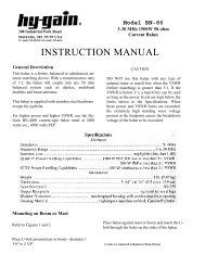
The next chart illustrates a message recorded under MSG1 that exceeds its allotted 32 second<br />
limit. Note that MSG1 continues to record beyond the partition, purging the previous contents of<br />
MSG2. When called up, all of MSG1 will play back without interruption. However, when<br />
MSG2 is called up, only that part of MSG1 falling in the MSG2 slot will play.<br />
9
<strong>MFJ</strong>-<strong>434B</strong> <strong>Instruction</strong> <strong>Manual</strong><br />
<strong>Voice</strong> <strong>Keyer</strong><br />
MSG1<br />
MSG2<br />
MSG3<br />
MSG4<br />
MSG5<br />
Slot Size in Seconds<br />
32 10 10 10 13<br />
0 32 42 52 62 75<br />
Total Time in Seconds<br />
This feature enables you to load up to a 75 second message in MSG1, should you need a long<br />
recording (progressively fewer slots are available as your message grows in length). When the<br />
memory limit is reached, the red Rec LED will stop blinking and the record function will stop<br />
automatically. With a little practice, you can use this protocol to extend your unit's flexibility.<br />
Message Playback<br />
Until you become fully familiar with your <strong>Voice</strong> <strong>Keyer</strong>'s operation, we suggest practicing with it<br />
disconnected from your transceiver. This will prevent accidental on air interference.<br />
1. Previewing Recorded Messages: Whenever the Xmit button is Off (out), you may<br />
select any message (MSG) in memory and listen to it on the monitor speaker without<br />
transmitting it over the air. Monitor playback level is adjusted via the Volume control<br />
on the keyer's front panel.<br />
2. Transmitting Recorded Messages: Whenever the Xmit button is On (in), any<br />
message (MSG) you select will be transmitted over the air.<br />
3. Single Play of a Recorded Message: To preview or transmit a message one time only, press<br />
the desired MSG switch briefly and release.<br />
4. Endless Loop Playback of a Recorded Message: To preview or transmit a message in<br />
endless loop mode, press and hold the desired MSG button for two seconds--until the green<br />
Play LED begins blinking. When you release the MSG button, the first playback will start. It<br />
will then repeat at the interval set by the Repeat Delay controls until halted.<br />
5. Adjusting the Endless Loop Delay Interval: The repeat interval begins at the end of the<br />
recorded message. The front panel knob labeled Repeat Delay adjusts the interval from 0.5-<br />
50 seconds in the X1 switch position and from 5-500 seconds in the X10 switch position. We<br />
recommend checking the interval time in preview mode (Xmit switch Off) before putting your<br />
message on air.<br />
6. Halting Playback of a Recorded Message: Any of the following actions will stop message<br />
playback immediately:<br />
A. Press the red Stop button to halt the message in progress.<br />
B. Press the PTT switch on your mic to halt the message in progress.<br />
10
<strong>MFJ</strong>-<strong>434B</strong> <strong>Instruction</strong> <strong>Manual</strong><br />
<strong>Voice</strong> <strong>Keyer</strong><br />
C. Press any other MSG button to halt the current message and start a new one.<br />
7. Adjusting the Output Level Control: Before attempting to transmit recordings on air, you<br />
must set the Output Level control on the back panel for your keyer. Begin by recording a test<br />
message into one of the MSG memories, being careful to speak at normal levels. Preview this<br />
message after recording to make sure it's okay before proceeding.<br />
Note that your transceiver's mic gain should be set to the position where you normally run it.<br />
The Output Level control is then adjusted to match the audio level produced by your station<br />
microphone. If possible, use a dummy load during this adjustment procedure to avoid generating<br />
needless on-the-air interference.<br />
A. Establish Normal Mic Level: Press the PTT and speak normally into your station mic,<br />
noting the average RF output level and ALC reading on the transceiver's meters.<br />
Important Note: Do not readjust transmitter Mic Gain during the following procedure. The<br />
<strong>Voice</strong> <strong>Keyer</strong>'s output level should be set to match the normal output level of your station<br />
microphone.<br />
B. Play Message: Make sure the keyer is in Play mode, and activate the Xmit switch (in).<br />
Now, activate your test message by pressing the appropriate MSG button. The radio should<br />
key automatically when the message begins, and drop out when it stops.<br />
C. Set Output Level Control: Find the Output Level screwdriver adjustment on the back panel<br />
and adjust it so the transceiver's meter readings approximate those from live speech. If your<br />
final adjustment falls in the bottom or top 1/4 of the pot's control range, we recommend<br />
resetting R29. To do this, first set the Output Level for its 12:00 o’clock (mid range) setting.<br />
Then, adjust R29 for the correct transmit level. This adjustment centers the Output Level<br />
control range, making fine level adjustments easier. See Other Internal Adjustments for<br />
more details on locating and setting R29.<br />
Self Test Mode<br />
The <strong>MFJ</strong>-434 features a self test mode for confirming correct operation. This sequence evaluates<br />
several functions, including all MSG buttons, remote port functions, LED’s, PTT function, repeat<br />
delay pot, and delay range switch.<br />
1. To start the self test, release all buttons (out position) and turn the Repeat Delay pot fully<br />
clockwise. Next, press Stop while turning Power on.<br />
2. The green LED should send a copyright message and software version number in Morse<br />
Code. To skip the copyright message and go straight to test, briefly press and release the<br />
MSG1 button.<br />
11
<strong>MFJ</strong>-<strong>434B</strong> <strong>Instruction</strong> <strong>Manual</strong><br />
<strong>Voice</strong> <strong>Keyer</strong><br />
3. Press the following buttons in the sequence shown. The green LED should blink once per<br />
operation.<br />
STOP → GREEN<br />
MSG1 → GREEN<br />
MSG2 → GREEN<br />
MSG3 → GREEN<br />
MSG4 → GREEN<br />
MSG5 → GREEN<br />
X1/X10 → GREEN<br />
STOP (REMOTE) → GREEN<br />
MSG1 (REMOTE) → GREEN<br />
MSG2 (REMOTE) → GREEN<br />
MSG3 (REMOTE) → GREEN<br />
MSG4 (REMOTE) → GREEN<br />
MSG5 (REMOTE) → GREEN<br />
PTT → GREEN<br />
4. Turn the Repeat Delay pot fully counter-clockwise, then fully clockwise. The green LED<br />
should blink once at each end of the pot.<br />
5. Press the Play/Rec button. The red LED should illuminate.<br />
6. If the unit passes this test, the red LED illuminates steadily. If there is an error, a failure<br />
message describing the problem will be sent through the LED using Morse code.<br />
External Control Circuits<br />
Lines available at the Remote IDC port permit installing an external remote control switch or PC<br />
computer interface. This feature provides external control of voice keyer message buttons<br />
MSG1-MSG5 and Stop. In addition, a transmit warning line (Xmit) is available to signal external<br />
devices when the keyer is activating the transmitter. Xmit is a 12 volt signal line sourced<br />
through a 10K resistor that goes low during transmit. Each memory control line (MSG1-MSG5<br />
and Stop) is a 5 volt open circuit that must be pulled to within 0.2 volts of ground to reliably<br />
activate or halt any message.<br />
Simple <strong>Manual</strong> Remote Switch<br />
The remote box shown below requires six (6) normally open momentary contact switches, a<br />
length of shielded 8 conductor cable, a 8 pin IDC connector, and a small box to hold the<br />
switches. The control line ground should be connected only at the remote port on the voice<br />
12
<strong>MFJ</strong>-<strong>434B</strong> <strong>Instruction</strong> <strong>Manual</strong><br />
<strong>Voice</strong> <strong>Keyer</strong><br />
keyer. The shield of the 8 conductor cable is connected to both the switch box chassis and voice<br />
keyer chassis. Do not connect the shield to the signal ground at either end, or erratic operation<br />
may result.<br />
REMOTE BOX<br />
IDC PLUG<br />
STOP<br />
MSG1<br />
MSG2<br />
MSG3<br />
MSG4<br />
MSG5<br />
NC<br />
XMIT<br />
GND (signal)<br />
Shield<br />
Computer Interface<br />
The <strong>MFJ</strong>-434 selects memories through a buffered CMOS or TLL compatible interface. While<br />
this interface is relatively immune to ground loops (it takes almost 3 V RMS ripple to cause<br />
erratic control), it is still a good idea to use careful wiring techniques.<br />
We recommend using the interface circuit shown below to protect the computer from external<br />
RF. Each 2N3904 transistor should be driven into saturation for reliable control. This normally<br />
requires at least 5 mA of base current.<br />
Locate the driver transistors at the computer, and fully shield all circuitry. Be sure to ground the<br />
emitters to the keyer's signal ground on the <strong>Voice</strong>-<strong>Keyer</strong>’ IDC plug only! Keep chassis ground<br />
and signal ground separate, or erratic operation may result.<br />
13
<strong>MFJ</strong>-<strong>434B</strong> <strong>Instruction</strong> <strong>Manual</strong><br />
<strong>Voice</strong> <strong>Keyer</strong><br />
Abort<br />
MEM1<br />
MEM2<br />
MEM3<br />
MEM4<br />
MEM5<br />
SW RET<br />
Computer<br />
Parts List<br />
R1-R6 470 Ohm<br />
R7-R12 1 K<br />
C1-C6 .01 uF<br />
Q1-Q6 2N3904<br />
R1<br />
R2<br />
R3<br />
R4<br />
R5<br />
R6<br />
Ground<br />
Shielded<br />
Multi-Conductor<br />
Cable<br />
R7<br />
C1<br />
R8<br />
C2<br />
R9<br />
C3<br />
R10<br />
C4<br />
R11<br />
C5<br />
Q1<br />
Q2<br />
Q3<br />
Q4<br />
Q5<br />
<strong>Voice</strong> <strong>Keyer</strong><br />
Stop<br />
MSG1<br />
MSG2<br />
MSG3<br />
MSG4<br />
MSG5<br />
XMIT<br />
Signal Ground<br />
Chassis Ground<br />
R12<br />
Q6<br />
C6<br />
following is a cross reference for NA software:<br />
The<br />
NA<br />
<strong>MFJ</strong><br />
ABORT STOP<br />
MEM (1-5) MSG (1-5)<br />
SW RET GND (Control Ground)<br />
GROUND Shield or Chassis Ground<br />
Trouble Shooting Guide<br />
<strong>Keyer</strong> Won't Power Up: Check power connections and cables. Also, check the voltage and<br />
polarity of your power source--it must be capable of providing 9-15 Vdc @ 100 mA. If running<br />
on 9V internal battery, check battery condition.<br />
XMIT Function and Station Mic PTT Function won't work: Check internal microphone<br />
jumper interface--does it match the type of transceiver you are using?<br />
Station Mic won’t work: Check the External Microphone Power Select. Internal jumpers<br />
(JMP6) must be set to the voltage that is closest to that specified by your microphone<br />
manufacturer.<br />
Station Mic Won't Record: Press the PTT switch—the mic element may be switched.<br />
Low or Excessive Transmit Audio on Playback: Has the Output Level Control been set for<br />
the transmitter currently in use? Does internal trimpot R29 need to be reset to bring the Output<br />
Level Control within the transceiver's drive range?<br />
14
<strong>MFJ</strong>-<strong>434B</strong> <strong>Instruction</strong> <strong>Manual</strong><br />
<strong>Voice</strong> <strong>Keyer</strong><br />
Distorted Recordings from Audio In Jack: Are levels from your audio source exceeding the<br />
keyer's 0-dBm maximum input rating? If so, they must be attenuated.<br />
Weak or Noisy Recordings from Audio In Jack: Are levels from your audio source below the<br />
-23 dBm minimum operating level? If so, they must be boosted in some way.<br />
<strong>Voice</strong> <strong>Keyer</strong> Won't Activate PTT line on Playback: Check XMIT switch position.<br />
Pre-recorded Messages Lost: Were higher numbered message slots accidentally overwritten<br />
when recording an excessively long message in a lower numbered slot? Also, check the status of<br />
the REC/PLAY switch. Was message playback attempted with the switch in REC mode? If so,<br />
the memories may have been purged by "dead air".<br />
No Monitor Audio: Is a jack plugged into the Audio Out connector on back? If so, the internal<br />
monitor speaker will be disconnected.<br />
MSG Control Erratic: Check remote jack and any remote control devices attached to it. Was<br />
the remote control ground line connected to chassis ground at some point?<br />
PTT Switch Fails to Halt Message Playback: Check JMP1--a shorting plug must be installed<br />
for the PTT override function to work.<br />
Hum and Distortion: In ham stations where several pieces of equipment are interconnected,<br />
unwanted hum, audio distortion, regeneration, and even sustained AF oscillations may result.<br />
This condition may be caused by RF feedback, but it's more likely an audio system groundloop<br />
(your keyer is heavily protected against RFI). To eliminate RF feedback as the cause, place the<br />
transmitter on a dummy load and run tests at full power level. If the audio problem disappears,<br />
it's probably RF related. If not, there's probably one or more groundloops in your station setup.<br />
Groundloops happen when signal grounds (mic lines, audio output lines, etc) are inadvertently<br />
connected to chassis grounds, or when audio patch cables between units are grounded at both<br />
ends creating multiple return paths. To solve the problem, begin by looking for multiple ground<br />
routes and for interconnected signal and chassis grounds. If eliminating these faults fails to<br />
resolve the condition, try installing isolation transformers on problematic audio lines. The more<br />
audio related equipment you interconnect, the more careful you have to be!<br />
TECHNICAL ASSISTANCE<br />
If you have any problem with this unit first check the appropriate section of this manual. If the<br />
manual does not reference your problem or your problem is not solved by reading the manual,<br />
you may call <strong>MFJ</strong> Technical Service at 662-323-0549 or the <strong>MFJ</strong> Factory at 662-323-5869.<br />
You will be best helped if you have your unit, manual and all information on your station handy<br />
so you can answer any questions the technicians may ask.<br />
You can also send questions by mail to <strong>MFJ</strong> Enterprises, Inc., 300 Industrial Park Road,<br />
Starkville, MS 39759; by Facsimile (FAX) to 662-323-6551; or by email to<br />
techinfo@mfjenterprises.com. Send a complete description of your problem, an explanation of<br />
exactly how you are using your unit, and a complete description of your station.<br />
15
<strong>MFJ</strong>-<strong>434B</strong> <strong>Instruction</strong> <strong>Manual</strong><br />
<strong>Voice</strong> <strong>Keyer</strong><br />
NOTES<br />
16
<strong>MFJ</strong>-<strong>434B</strong> <strong>Instruction</strong> <strong>Manual</strong><br />
<strong>Voice</strong> <strong>Keyer</strong><br />
APPENDIX<br />
-At the <strong>MFJ</strong> factory, the interface is set for Yaesu transceivers with modular microphone<br />
connectors (FT-817, FT-857, FT-897).<br />
Icom IC-703<br />
IC-706<br />
(modular)<br />
Icom IC-718<br />
IC-725<br />
IC-746<br />
IC-756<br />
(8-pin round)<br />
Kenwood TS-50<br />
TS-570<br />
TS-870<br />
TS-2000<br />
(8-pin round)<br />
Kenwood TS-480<br />
(modular)<br />
JMP 9<br />
JMP 8<br />
JMP 7<br />
JMP 6<br />
JMP 5<br />
JMP 4<br />
JMP 3<br />
JMP 2<br />
JMP 9<br />
JMP 8<br />
JMP 7<br />
JMP 6<br />
JMP 5<br />
JMP 4<br />
JMP 3<br />
JMP 2<br />
JMP 9<br />
JMP 8<br />
JMP 7<br />
JMP 6<br />
JMP 5<br />
JMP 4<br />
JMP 3<br />
JMP 2<br />
JMP 9<br />
JMP 8<br />
JMP 7<br />
JMP 6<br />
JMP 5<br />
JMP 4<br />
JMP 3<br />
JMP 2<br />
1 2 3 4 5 6 7 8<br />
1 2 3 4 5 6 7 8<br />
1 2 3 4 5 6 7 8<br />
1 2 3 4 5 6 7 8<br />
Mic<br />
Mic Gnd<br />
PTT<br />
PTT Gnd<br />
Direct<br />
Mic<br />
Mic Gnd<br />
PTT<br />
Mic<br />
Mic Gnd<br />
PTT<br />
PTT Gnd<br />
Direct<br />
Mic<br />
Mic Gnd<br />
PTT<br />
Mic<br />
Mic Gnd<br />
PTT<br />
PTT Gnd<br />
Direct<br />
Mic<br />
Mic Gnd<br />
PTT<br />
Mic<br />
Mic Gnd<br />
PTT<br />
PTT Gnd<br />
Direct<br />
Mic<br />
Mic Gnd<br />
PTT<br />
JMP 9<br />
Y aesu FT-817 JMP 8<br />
JMP 7<br />
FT-857<br />
JMP 6<br />
FT-897<br />
JMP 5<br />
JMP 4<br />
(modular)<br />
JMP 3<br />
JMP 2<br />
1 2 3 4 5 6 7 8<br />
Mic<br />
Mic Gnd<br />
PTT<br />
PTT Gnd<br />
Direct<br />
Mic<br />
Mic Gnd<br />
PTT<br />
Y aesu FT-847<br />
(8-pin round)<br />
JMP 9<br />
JMP 8<br />
JMP 7<br />
JMP 6<br />
JMP 5<br />
JMP 4<br />
JMP 3<br />
JMP 2<br />
1 2 3 4 5 6 7 8<br />
Mic<br />
Mic Gnd<br />
PTT<br />
PTT Gnd<br />
Direct<br />
Mic<br />
Mic Gnd<br />
PTT<br />
17
<strong>MFJ</strong>-<strong>434B</strong> <strong>Instruction</strong> <strong>Manual</strong><br />
<strong>Voice</strong> <strong>Keyer</strong><br />
Schematic<br />
18
<strong>MFJ</strong>-<strong>434B</strong> <strong>Instruction</strong> <strong>Manual</strong><br />
<strong>Voice</strong> <strong>Keyer</strong><br />
19
<strong>MFJ</strong>-<strong>434B</strong> <strong>Instruction</strong> <strong>Manual</strong><br />
<strong>Voice</strong> <strong>Keyer</strong><br />
20
<strong>MFJ</strong>-<strong>434B</strong> <strong>Instruction</strong> <strong>Manual</strong><br />
<strong>Voice</strong> <strong>Keyer</strong><br />
21