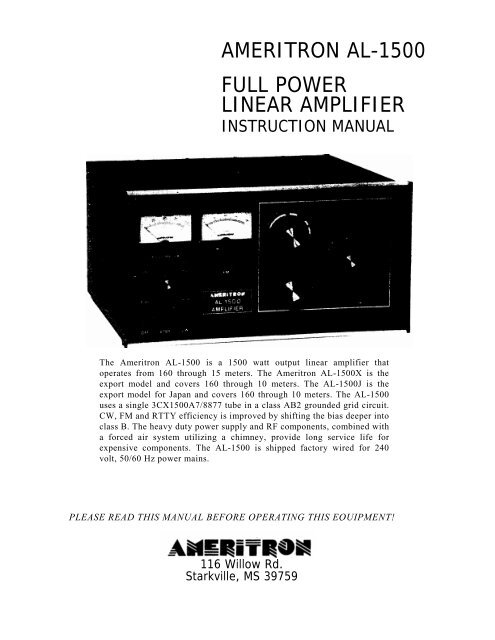
AMERITRON AL-1500 FULL POWER LINEAR AMPLIFIER - QRZCQ
AMERITRON AL-1500 FULL POWER LINEAR AMPLIFIER - QRZCQ
AMERITRON AL-1500 FULL POWER LINEAR AMPLIFIER - QRZCQ

Create successful ePaper yourself
Turn your PDF publications into a flip-book with our unique Google optimized e-Paper software.
<strong>AMERITRON</strong> <strong>AL</strong>-<strong>1500</strong><br />
<strong>FULL</strong> <strong>POWER</strong><br />
<strong>LINEAR</strong> <strong>AMPLIFIER</strong><br />
INSTRUCTION MANU<strong>AL</strong><br />
The Ameritron <strong>AL</strong>-<strong>1500</strong> is a <strong>1500</strong> watt output linear amplifier that<br />
operates from 160 through 15 meters. The Ameritron <strong>AL</strong>-<strong>1500</strong>X is the<br />
export model and covers 160 through 10 meters. The <strong>AL</strong>-<strong>1500</strong>J is the<br />
export model for Japan and covers 160 through 10 meters. The <strong>AL</strong>-<strong>1500</strong><br />
uses a single 3CX<strong>1500</strong>A7/8877 tube in a class AB2 grounded grid circuit.<br />
CW, FM and RTTY efficiency is improved by shifting the bias deeper into<br />
class B. The heavy duty power supply and RF components, combined with<br />
a forced air system utilizing a chimney, provide long service life for<br />
expensive components. The <strong>AL</strong>-<strong>1500</strong> is shipped factory wired for 240<br />
volt, 50/60 Hz power mains.<br />
PLEASE READ THIS MANU<strong>AL</strong> BEFORE OPERATING THIS EQUIPMENT!<br />
116 Willow Rd.<br />
Starkville, MS 39759
UNPACKING INSTRUCTIONS<br />
1. Carefully remove the amplifier, transformer, and tube from their shipping cartons.<br />
Inspect each item for visible damage. If any damage occurred during shipment,<br />
notify the transportation company immediately.<br />
2. Save all packing materials in case you need to return your <strong>AL</strong>-<strong>1500</strong>(X/J) for factory<br />
service. The cartons have been designed to give maximum protection for this<br />
amplifier. Any units returned without proper packing may be damaged and shipping<br />
claims cannot be made. Contact the factory before returning any units.<br />
3. Remove the screws that hold the cover to the amplifier. Slide the cover back and<br />
remove it from the amplifier. There is a small bag that contains the fuses, fuse caps<br />
and the remainder of the chassis screws wrapped in the packing material around the<br />
anode connector.<br />
4. Please read the GENER<strong>AL</strong> INFORMATION and SPECIFICATIONS sections before<br />
attempting to install the transformer and tube. Please note that the tube chimney comes<br />
factory installed around the tube socket. Go to the INST<strong>AL</strong>LATION section on page 4<br />
to begin installing the transformer and tube.<br />
5. This amplifier must always be disconnected from the power mains before removing<br />
the cover. See the precaution on page 10. Please read the entire manual to become<br />
familiar with the operation of the <strong>AL</strong>-<strong>1500</strong>(X/J) amplifier.<br />
NOTE: The <strong>AL</strong>-<strong>1500</strong>J is the Japanese export version of the <strong>AL</strong>-<strong>1500</strong> amplifier. The<br />
<strong>AL</strong>-<strong>1500</strong>J utilizes a special power transformer for use with 200V AC, 50 Hz. The<br />
<strong>AL</strong>-<strong>1500</strong>J will perform to specifications with the special transformer installed and<br />
will cover 24 and 28 MHz.
FEATURES<br />
1. High performance tube: the <strong>AL</strong>-<strong>1500</strong> uses a single rugged<br />
3CX<strong>1500</strong>A7/8877 tube.<br />
2. High power gain: the 3CX<strong>1500</strong>A7/8877 features high<br />
power gain. As little as 65 watts of drive power will pr<br />
vide <strong>1500</strong> watts of output power.<br />
3. SSB/CW switch: the bias voltage is switched to provide<br />
the best linearity on SSB or the lowest dissipation on CW<br />
operation.<br />
4. <strong>AL</strong>C Indicator: the drive level is detected to provide a<br />
control voltage for the exciter. <strong>AL</strong>C prevents overdriving<br />
of the linear and reduces distortion from excessive drive<br />
power.<br />
5. Vernier Plate and Load Adjustments: both tuning controls<br />
have vernier 6:1 reduction drives for smooth tuning.<br />
6. Two Illuminated Panel Meters: the <strong>AL</strong>-<strong>1500</strong> has two illuminated<br />
panel meters. The Grid Current meter provides<br />
a continuous reading of grid current and indicates<br />
proper operation of the amplifier. The other meter reads<br />
Plate Voltage (HV), Plate Current (IP), Peak RF Watts<br />
(PO) and <strong>AL</strong>C.<br />
7. Operate/Standby Switch: filament and plate voltages are<br />
maintained while allowing the amplifier to be bypassed<br />
for "barefoot" operation.<br />
8.12 Volt Auxiliary Jack: 12 volts at 100 mA is provided for<br />
accessories such as the ATR-15 Antenna tuner.<br />
9. XMT Indicator LED: provides a front panel indication of<br />
proper amplifier keying by the exciter during operation.<br />
10. Grid Overload Circuit: this amplifier has a circuit that<br />
protects the tube from excessive grid current. If 175 mA of<br />
peak grid current is reached the "OPR" LED will no longer<br />
light and the amplifier will go into a bypass condition. This<br />
overload condition can be reset by momentarily putting the<br />
STBY/OPR switch in the STBY position.<br />
Caution: This amplifier must be disconnected from the power<br />
mains before removing the cover. See the warning on page<br />
10.<br />
TECHNIC<strong>AL</strong> SPECIFICATIONS <strong>AL</strong>-<strong>1500</strong><br />
Input:<br />
Circuit type: Pi-network, slug tuned coils Maximum VSWR<br />
at resonance: 1.3:1 Minimum 2:1 VSWR bandwidth: 20% of<br />
center frequency Maximum drive power permissable: 100<br />
watts Typical drive for full power output: 65 watts<br />
Output:<br />
Circuit type: Pi-L, Pi<br />
/2 hour continuous carrier: <strong>1500</strong> watts 30 second<br />
continuous carrier: 2500 watts<br />
1/2 hour PEP two-tone test: 2500 watts plus 30 second<br />
PEP two-tone test: 2500 watts plus<br />
Power Supply:<br />
Circuit type: full wave bridge, capacitor input<br />
No load voltage: 3600 V<br />
Full load voltage: 3300 V<br />
Full load current: 1 amp<br />
Regulation: 10% typical<br />
Transformer: 34 lbs., hypersil<br />
Capacitors: 26 mfd total, computer grade<br />
Maximum draw at rated output: 15 amps at 240V AC 50/60 Hz<br />
Tube:<br />
Type:(1) 3CX<strong>1500</strong>A7/8877<br />
Continuous dissipation: <strong>1500</strong> Watts<br />
Warm-up time: 180 seconds<br />
Metering:<br />
Multimeter: Plate current, plate voltage, drive/<strong>AL</strong>C, power<br />
output (PEP watts)<br />
Grid: Grid current<br />
<strong>AL</strong>C: Negative going, 0-20V, adjustable, phono jack<br />
Efficiency CW: 65% typical<br />
Efficiency SSB (envelope crest): 62%<br />
MARS/WARC: yes, set to nearest highest amateur band<br />
Keying: Requires relay closure or sinking to ground of t 12V<br />
DC at 100 mA, phono jack<br />
RF Connectors: S0239<br />
Line Connector: NEMA 6-15P, 240V style<br />
Dimensions: 18 1/2 D x 17 W x 10 H<br />
Weight: 77 lbs.<br />
Frequency Coverage: (<strong>AL</strong>-<strong>1500</strong>)-1.8, 3.5, 7, 14, 18 and 21<br />
MHz. User modified models cover 24 and 28 MHz. (<strong>AL</strong>-<br />
<strong>1500</strong>X/J) Export models-1.8, 3.5,7, 14, 18, 21, 24 and 28<br />
MHz.<br />
Third Order IMD at Rated Output: -36 dB
SAFETY INTERLOCK<br />
While the Amplifier's top cover is in place, the interlock switch<br />
closes to allow AC line voltage to reach the power transformer.<br />
When the top cover is removed, the interlock opens and<br />
disconnects the line voltage. This does not discharge the bank<br />
of power supply filter capacitors. Be sure to allow the filter<br />
capacitors to discharge before you touch anything inside the<br />
Amplifier. You can select the High Voltage function of the<br />
Multimeter to check the high voltage potential. Never attempt to<br />
defeat the safety interlock. WARNING- Never remove the cover<br />
of this amplifier with the unit plugged into the power line.<br />
DRIVING <strong>POWER</strong><br />
This Amplifier is designed to operate at full ratings when it is<br />
driven by an exciter that has approximately 65 watts of RF<br />
output. You can use an exciter that has lower output power, but<br />
the Amplifier's output will be less. If you use an exciter that<br />
delivers more than 100 watts, carefully adjust the driving power<br />
to avoid "over drive" and the creation of spurious signals, which<br />
create needless interference to other operators. We highly<br />
recommend that you use a monitor scope for continuous output<br />
monitoring. The display on an oscilloscope is the best way of<br />
determining the amplitude of the voice peaks which, if<br />
excessive. can cause "flat topping" and splatter. This amplifier<br />
has a circuit that protects the tube from excessive grid current. If<br />
175 mA of peak grid current is reached, the "OPR" LED will no<br />
longer light and the amplifier will go into a bypass condition.<br />
This overload condition can be reset by momentarily putting the<br />
STBY/OPR switch in the STBY position.<br />
IMPORTANT: In no case should you advance the power output<br />
control of your exciter beyond the point where the Amplifier's<br />
Power Output indication ceases to increase. If you turn the<br />
control past this point, nonlinear operation may occur.<br />
FILAMENT SUPPLY<br />
The filament circuit of this amplifier satisfies all requirements<br />
of the tube manufacturer related to tube performance and life.<br />
Inrush current is controlled by the transformer internal<br />
resistance and impedance, filament choke resistance and<br />
filament wiring resistance. To insure maximum life of the tube<br />
never replace any circuit components or wiring with substitute<br />
parts.<br />
GENER<strong>AL</strong> INFORMATION<br />
mal continuous amateur operation at <strong>1500</strong> watt levels. Power is<br />
applied through RLY2 when the 12V DC low voltage supply is<br />
activated. A 10 ohm resistor limits the line current during the<br />
filter capacitor charge time to lower the stress on components.<br />
When the primary voltage approahces the full line value, RLY3<br />
shorts the 10 ohm resistor and applies the full line voltage to the<br />
plate transformer. The 10 ohm resistor acts as a fuse during<br />
start-up if the high voltage supply has a short.<br />
TIMER OVERLOAD BOARD<br />
The <strong>AL</strong>-<strong>1500</strong> has a circuit board mounted on the front panel<br />
side of the filter capacitor board that provides time delay to<br />
insure the cathode of the 3CX<strong>1500</strong>A7/8877 has reached proper<br />
operating temperature before high voltage and RF drive power<br />
can be applied. This board also samples the peak grid current<br />
and removes drive if the grid current is excessive.<br />
The timer portion if this circuit board uses IC1A as a comparator<br />
to drive the complimentary darlington 01 and 02. When<br />
twelve (12) volts is first applied to terminal "Y" diode D3<br />
provides a regulated 5.1 volt reference. Divider R8 and R7<br />
reduces the reference voltage to 3.7 volts. C9 charges from<br />
current supplied by R9. After approximately three minutes, the<br />
comparator output (pin 1) goes high. Q3's collector goes low<br />
and turns on Q2 and Q1. If the 12 volt supp!y is momentarily<br />
interrupted diode D1 discharges C9 through R6, R7, and R8.<br />
Any interruption of more than a few seconds requires a<br />
complete timing cycle to begin again.<br />
The grid overload circuit compares the voltage developed<br />
across the grid shunt (.3V equals 200mA) to the .256V reference<br />
provided by R5 and R11. This sets the grid trip at 175 mA. Pin 7<br />
of IC 18 will go high and turn 04 on if the grid current reaches<br />
175 mA. This will cause RLY 1 to latch on and remove the 12<br />
volts from the antenna transfer relay in the amplifier. The circuit<br />
is reset by putting the amplifier on standby momentarily. This<br />
removes the voltage that holds RLY 1 locked on. NOTE: The<br />
grid overload circuit will respond much faster than the grid meter<br />
can indicate grid current. if the overload continuously trips, the<br />
likely cause is excessive peak grid current. This is caused by the<br />
loading control being set too low (counter-clockwise) for the<br />
peak drive power applied to the amplifier.<br />
EXPORT MODIFICATIONS<br />
The low voltage tap on the filament transformer primary provides<br />
the ability to operate the blower at slower speeds for<br />
reduced noise. Normal amateur operation in CW and SSB will<br />
not cause heat damage to components on any recommended tap.<br />
It is always advisable to use the maximum speed (air flow) that<br />
the level of noise permits to extend component life. Wiring<br />
information for the blower is shown in the "Transformer<br />
Connections" instructions.<br />
A simple modification will allow operation on frequencies<br />
above 15 meters. Instructions for this modification are available<br />
by sending a written request for "Export Modification<br />
Instructions" along with a copy of a valid amateur license.<br />
There is no charge for this information. Export models are<br />
shipped with this modification and have an "X or J" following<br />
the serial number. Standard frequency coverages are indicated<br />
in the chart following the tuning instructions on page 10.<br />
PLATE SUPPLY<br />
The plate supply has a full wave bridge rectifier and a 1.8 KVA<br />
CCS rated tape wound hypersil transformer. Filtering is<br />
accomplished by a bank of high quality capacitors totaling 26<br />
mfd (additional capacitance will not improve supply<br />
performance). The Plate Supply will not be harmed by nor
METERING FUNCTIONS<br />
The <strong>AL</strong>-<strong>1500</strong> has two illuminated meters. The Grid Current meter<br />
provides a continuous indication of the 3CX<strong>1500</strong>/8877 grid<br />
current. This exclusive feature of Ameritron amplifiers indicates<br />
proper amplifier operation better than any other parameter. Do<br />
not exceed 75 mA on this meter during normal operation of this<br />
amplifier. The other meter reads Plate Voltage (HV), Plate<br />
Current (IP), Peak RF Watts (PO) and <strong>AL</strong>C. These functions are<br />
selected with the Multimeter Switch.<br />
Plate Voltage (HV): Read DC Plate Voltage on the 4000 volt<br />
scale. This scale is 100 volts per division. Normal voltages are<br />
3600 volts no load, 3300 volts full load.<br />
Plate Current (Ip): Read DC Plate Current on the 1000 mA scale.<br />
This scale is 25 mA per division.<br />
Peak RF Watts (PO): Read Peak RF Watts on the 2000 watt<br />
scale. This scale has 50 watt divisions below 1000 watts and 100<br />
watt divisions above 1000 watts.<br />
NOTE: This circuit uses an emitter follower to charge a<br />
capacitor to the peak envelope voltage detected by the<br />
<strong>AL</strong>C/Power Board. Accurate peak envelope power readings are<br />
given when the amplifier is connected to a 50 ohm nonreactive<br />
load. If the amplifier is used with a mismatched load, the power<br />
meter will read higher or lower than normal by a ratio up to the<br />
value of the SWR. Potentiometer<br />
R5 on the Meter Board (50-01140-1) adjusts the calibration of the<br />
power meter.<br />
<strong>AL</strong>C: Indicates a relative drive level (average, not PEP) that can<br />
be estimated by dividing the Peak RF Watts scale by 10.<br />
TECHNIC<strong>AL</strong> ASSISTANCE<br />
Technical assistance is available during our normal business<br />
hours on weekdays. The following information is required to<br />
assist you with operational problems:<br />
1. Model and Serial Number<br />
2. Date of purchase and dealer<br />
3. An accurate description of the problem<br />
Meter readings at all stages of the tuning proceedure are very<br />
important along with a complete description of the other<br />
equipment used with our product.<br />
Written assistance is also available. Due to time delays in<br />
processing mail, please allow at least three weeks for a writ<br />
ten reply.<br />
<strong>AMERITRON</strong> 116<br />
Willow Road<br />
Starkville, MS 39759<br />
Tel: (662) 323-8211<br />
Fax: (662) 323-6551<br />
PERIODIC MAINTENANCE<br />
The high voltage present on the plate choke and air variable<br />
capacitors attracts dust and dirt out of the air stream. It is<br />
particularly important that the high voltage areas at the bottom of<br />
the plate choke and the insulators on the air variable capacitors be<br />
dust free. These areas should be inspected every few months if<br />
the amplifier is operated in a dusty environment. Unplug the line<br />
cord, and wait about 90 seconds until the power supply capacitors<br />
discharge. Check the HV scale for zero voltage before removing<br />
the cover. Remove the cover. You must first connect a jumper<br />
wire from ground or chassis to the anode connection of the tubes.<br />
NOTE: This is a safety wire that must be installed when<br />
beginning service work. After service is complete, reverse the<br />
procedure to remove the safety wire. Remove the wire from the<br />
anode connection first and then from ground.<br />
Use a soft bristle brush dipped in alcohol to clean areas mentioned<br />
previously. In the event that cleaning is required at<br />
frequent intervals, place a low restriction air filter material over<br />
the air inlet holes on the left front side of the cabinet near the<br />
filter capacitors. Most hardware stores stock suitable materials<br />
that are used as replacement filters for window air conditioners.<br />
TRANSFORMER INST<strong>AL</strong>LATION<br />
Remove the cover of the amplifier. Remove the small package<br />
that is wrapped around the anode connector. This is the fuse pack<br />
and contains the fuses, fuse caps and the remainder of the chassis<br />
screws. Remove the top 7/16" nuts from the four transformer<br />
mounting bolts inside of the amplifier. Carefully remove the<br />
transformer from its shipping carton.<br />
Place the transformer on the four 1 /4-20 mounting bolts. Use care<br />
because the transformer is heavy. The side with the two high<br />
voltage secondary RED leads must be adjacent to<br />
INST<strong>AL</strong>LATION<br />
the center panel(see Fig. 1). Now place a 7/16" nut on each bolt<br />
(see Fig. 2). Snug the nuts down manually. Do not tighten with a<br />
ratchet wrench.<br />
Remove the brass 1 /4" hex nuts and the top flat washer from the<br />
two 6-32 screws on the rectifier board (see Fig. 1). Install the<br />
RED lead ring terminals on the screws and replace the flat<br />
washers and 1 /4" hex nuts. Position the wires so that the black<br />
insulated areas are at least 1 /4" from each other and any metal<br />
objects. Now tighten the 1 /4" hex nuts.
TRANSFORMER INST<strong>AL</strong>LATION Cont.<br />
For 240V Operation (factory wired):<br />
Fig. 3<br />
The four primary leads have colored plastic insulating boots<br />
over the quick disconnect terminals. Slide these back prior to<br />
installing the leads. !nstall the color coded boots as<br />
follows:(see Fig. 1) Note: Japanese export model (<strong>AL</strong>-<strong>1500</strong>J)<br />
should follow the 240V operation steps to properly connect<br />
their transformers. The <strong>AL</strong>-<strong>1500</strong>J is supplied with a special<br />
transformer for 200V operation.<br />
1. BLUE (Brown wire) to the top relay terminal<br />
2. YELLOW (Black/White) to the top terminal of terminal<br />
block<br />
3. CLEAR (Black wire) to the second terminal of terminal<br />
block<br />
4. RED (Brn/Wht) to the bottom terminal of terminal block<br />
Now slide the colored insulating boots back over the terminals.<br />
Note: The green wire is not used for 240V operation.<br />
There is no green wire on the <strong>AL</strong>-<strong>1500</strong>J export model<br />
transformer.<br />
Important: The leads must be in the positions indicated by<br />
the color coded insulating boots(see Fig. 1) for 240V operation.<br />
Or for 200V operation in Japan. Caution: Do not use<br />
the 220V wiring unless the line voltage is always below 220<br />
VAC. The Standard USA voltage is 240 VAC, not 220.<br />
TUBE INST<strong>AL</strong>LATION<br />
Note that one of the tube pins is larger in diameter. This<br />
larger pin "keys" the tube base and socket. Install the tube by<br />
aligning the tube pins with the socket contact terminals, then<br />
seat the tube with vertical pressure ONLY. Do not "rock" or<br />
"twist" the tube. Also the chimney is already mounted inside<br />
the <strong>AL</strong>-<strong>1500</strong> amplifier.<br />
After the tube is installed, attach the anode connector as<br />
follows: (Refer to the Fig. 4)<br />
. Remove screw "A" that holds the anode connector<br />
to the 500pf blocking capacitors.<br />
2. Attach the anode connector to the tube anode.<br />
3. Insert screw "A" into the 500pf capacitors and<br />
snug it down.<br />
Fig. 4<br />
For 220V operation (see Fig. 3), follow the first three steps<br />
above, then follow the steps below:<br />
1. Slide the RED boot back on the BRN/WHT<br />
wire.<br />
2. Clip the terminal connector off the wire and slide<br />
the RED boot off.<br />
3. Remove the restraint from the GRN wire and<br />
slide the RED boot on to the wire.<br />
4- Solder the terminal connector to the GRN wire.<br />
5. Tape up the BRN/WHT wire because it will 5<br />
not be used.<br />
Top View of <strong>1500</strong> Tube
Caution: This page is only valid for transformers that contain these exact color codes for the primary winding. Early<br />
production units did not contain a multiple tap transformer. If the terminal strip has all these color coded wires, then the<br />
unit has the multiple tap transformer.<br />
FILAMENT/BLOWER WIRING INSTRUCTIONS<br />
The <strong>AL</strong>-<strong>1500</strong> and <strong>1500</strong>(X) amplifiers come prewired for 240V line voltage and with the blower prewired for medium<br />
high fan speed. NOTE: The <strong>AL</strong>-<strong>1500</strong>J Japanese export model is prewired for 208V line voltage. This page gives filament<br />
transformer connection details for various line voltages and blower speeds. The five lug terminal strip and the single lug<br />
terminal strip are located immediatgly behind the ON/OFF rocker switch inside the unit. The drawing below shows the<br />
connection of transformer leads and their purpose.<br />
This chart shows the color code of the transformer leads and their purpose. The number in parenthesis<br />
indicates the number of the terminal lug that the transformer lead is connected to. The<br />
number three (3) lug is not used to change the filament or blower wiring. Do not add or remove any<br />
wires from the number three (3) lug. Refer to the drawing above. Use the lug numbers above when<br />
referring to both of the Filament connection chart and the Blower connection chart below.<br />
FILAMENT TRANSFORMER LINE VOLTAGE T h ere<br />
are two wires that connect to the terminal lugs which<br />
determine the Filament Line Voltage. The BLACK wire<br />
from the power switch and WHITE wire from rear of the<br />
unit connect to different terminal lugs depending on the<br />
voltage desired. The <strong>AL</strong>-<strong>1500</strong> and <strong>1500</strong>(X) come prewired<br />
for 240V operation*. <strong>AL</strong>-<strong>1500</strong>J comes prewired for 200V<br />
operation**. Refer to the chart below. The voltage listed in<br />
the chart below is the maximum line voltage that should be<br />
applied to a given tap. Operation with line voltage in<br />
excess of 'he tan voltage selected can result in a reduction<br />
of tube life<br />
BLOWER CONNECTIONS<br />
The GREEN and WHITE wires from the rear of the unit<br />
connect to the terminal lugs to control the air speed of the<br />
fan. The <strong>AL</strong>-<strong>1500</strong>/X/J are prewired for the medium high<br />
speed setting*. Refer to the char below. The blower<br />
connections can be moved to lower speed taps if air noise<br />
is excessive. Ameritron recommends using the highest<br />
speed tap that noise considerations permit. The lowest<br />
speed tap will develop sufficient air flow for standard<br />
amateur SSB and CW full power operation. The highest<br />
speed taps should be used for contest or RTTY operation.
INTERCONNECTION<br />
S<br />
1. Connect the RF output of the exciter to the RF IN connector<br />
on the rear of the <strong>AL</strong>-<strong>1500</strong> with 50 ohm coax. Use any good<br />
quality 50 ohm cable long enough to connect the amplifier to<br />
the exciter. The amplifier uses a standard SO-239 female that<br />
will mate to a PL-259 male connector on the cable.<br />
2. Connect the existing station antenna system to the RF OUT<br />
connector on the rear of the <strong>AL</strong>-<strong>1500</strong> with RG-8 type coax.<br />
This connection uses PL-259 connectors.<br />
3. Use shielded audio type cable with standard male phono plugs<br />
to connect to the RELAY jack on the <strong>AL</strong>-<strong>1500</strong>. This jack<br />
has positive 12V DC open circuit and supplies<br />
100mA of current when pulled to ground.<br />
4. Connect a short ground lead from a good earth and RF ground<br />
to the GND terminal.<br />
5. The 12V connection on the rear panel provides 12V DC at 100<br />
mA maximum to operate external dial lamps or accessories<br />
such as the ATR-15 Antenna Tuner.<br />
6. DO NOT CONNECT THE "<strong>AL</strong>C OUT" SOCKET ON THE<br />
<strong>AMPLIFIER</strong> TO THE "<strong>AL</strong>C" SOCKET ON THE<br />
TRANSMITTER UNTIL INSTRUCTED TO DO SO IN<br />
THE TUNE UP PROCEDURE. This jack provides up to 20<br />
Volts of negative voltage for transmitter gain control.
LOCATION<br />
-Do not operate the Amplifier in excessively warm locations<br />
or near heating vents or radiators. Be sure air can circulate<br />
freely around and through the Amplifier cabinet. Provide an<br />
unobstructed air inlet for the blower. Do NOT place anything<br />
that will impede the free flow of air within 2 inches of the<br />
cabinet ventilation holes.<br />
INST<strong>AL</strong>LATION Cont.<br />
<strong>POWER</strong> CONNECTIONS<br />
The <strong>AL</strong>-<strong>1500</strong> is supplied with a NEMA 6-15P plug for 240V<br />
AC operation. Operation with power main voltages below<br />
200 volt is not recommended. Special transformers are required<br />
for 200V, 50/60 Hz operation (see NOTE on page 1).<br />
Refer to the "Transformer Installation" section on pages 4<br />
and 5 for the correct wiring for 220 to 240 volt operation.<br />
VENTILATION<br />
The <strong>AL</strong>-<strong>1500</strong> ventilation system has been designed and<br />
tested to maintain tube seal temperature safely below the<br />
tube manufacturer's rating at <strong>1500</strong> watts output with a 100%<br />
duty cycle when properly tuned. The blower in the <strong>AL</strong>-<strong>1500</strong><br />
is a permanently lubricated type that requires no maintainence<br />
in normal operation. To insure proper ventilation in<br />
your installation, observe the following:<br />
1. Do not block or unduly restrict the ventilation holes in<br />
the cover. Be sure that the amplifier is located in an area<br />
so the vent holes have open air circulation.<br />
2. The exhaust air flow is over 30 CFM. Do not "assist" the<br />
air flow unless the fan exceeds the <strong>AL</strong>-<strong>1500</strong> blower<br />
CFM by a factor of 2:1.<br />
3. Do not mount additional fans on the <strong>AL</strong>-<strong>1500</strong> cabinet.<br />
4. The exhaust air will become quite warm at higher power<br />
levels. Do not place any heat sensitive objects in the<br />
exhaust air stream.<br />
NEVER REWIRE THE <strong>POWER</strong> SUPPLY TO BOOST<br />
THE HIGH VOLTAGE ABOVE 3700 VOLTS.<br />
The wiring between the fuse box and the amplifier AC outlet<br />
must be No. 12 gauge or larger in order to supply the current<br />
required (13 amperes) without a significant drop in the line<br />
voltage. The outlet should be fused for 20 amperes.<br />
GROUNDING<br />
Connect a good RF and earth or water pipe ground to the<br />
ground post on the rear panel of the Amplifier. Use the<br />
heaviest and shortest connection possible.<br />
Before you use a water pipe ground, inspect the connections<br />
around the water meter and make sure that no plastic or rubber<br />
hose connections are used. These connections interrupt<br />
electrical continuity to the water supply line. Install a jumper<br />
around any insulating water connections you may find. Use<br />
heavy copper wire and pipe clamps. It is best to ground all<br />
equipment to one point at the operating position and then<br />
ground this point as described above.<br />
Proper tuning of a grounded grid linear amplifier is best<br />
accomplished with an understanding of what each control<br />
does and what the meters are telling the operator about the<br />
condition of TUNE.<br />
TUNING INSTRUCTIONS<br />
ing operation. Excessive grid current, distortion on SSB or<br />
arcing in the tank components occurs when full drive power<br />
is applied to the amplifier without the "LOAD"' set for<br />
enough clockwise (higher loading).<br />
The tuning controls function as follows:<br />
PLATE: This control tunes the amplifier output circuit to the<br />
operating frequency. It should always be adjusted for<br />
maximum output power or maximum grid current. Due to<br />
interaction with the ''LOAD" control, a "touch-up" should be<br />
performed after any load adjustments.<br />
LOAD: This control adjusts the coupling of amplifier to the<br />
antenna or load. It should be adjusted to keep the grid<br />
current in the proper operating range. As the loading<br />
capacitance is reduced (by rotating the control to a higher<br />
front panel number), the coupling is increased. An increase<br />
in coupling will reduce grid current and increase the amount<br />
of drive the amplifier will accept without component<br />
damage.<br />
A common mistake in tuning is to adjust the "LOAD"<br />
control at low drive powers and apply more drive dur<br />
It is important to remember the loading must be set properly<br />
for the PEAK power the amplifier is expected to develop. 50<br />
watts PEP will be the maximum drive the amplifier will<br />
safely handle if the output of the amplifier is tuned with 50<br />
watts of carrier drive. Any attempt to go beyond the amount<br />
of drive power the amplifier was originally tuned at will<br />
result in a rapid increase in grid current, splatter and even<br />
damage to components.<br />
The "LOAD" control should be adjusted for maximum<br />
output power without exceeding the recommended grid<br />
current. DO NOT USE THE LOAD CONTROL TO<br />
REDUCE <strong>POWER</strong> IN A GROUNDED GRID <strong>AMPLIFIER</strong>.<br />
The drive from the exciter should be reduced if the amplifier<br />
plate current or output power is excessive. The "LOAD"<br />
setting should be increased if grid current is excessive. Any<br />
errors in adjusting this control should be made in favor of a<br />
higher load setting (clockwise).
CW PROCEDURE<br />
Follow these instructions in numerical order. If the various meter<br />
readings are different than indicated, check the connections from<br />
the exciter to the amplifier and make sure they are correct.<br />
Consult the manual for the exciter.<br />
Be sure the transformer is correctly installed and wired for your<br />
line voltage. See the "Transformer Installation" section on page 4<br />
and 5 for wiring details.<br />
1. Set the <strong>AL</strong>-<strong>1500</strong> front panel switches as follows:<br />
<strong>POWER</strong> TO OFF<br />
OPR-STBY TO STBY<br />
SSB-CW TO CW<br />
MULTIMETER TO HV<br />
2. Plug the AC line cord into the proper voltage outlet.<br />
3. Set the Power Switch to the ON position. The grid meter<br />
should light and the blower should start. After three minutes,<br />
the plate meter should light and the multimeter should read<br />
3600 volts nominal and absolutely no more than 3700 volts<br />
HV.<br />
4. With the amplifier still on STANDBY. tune the exciter into a<br />
normal 50 ohm load according to the manufacturer's<br />
instructions. Turn the exciter drive fully down after tuning.<br />
5. Place the amplifier mode switch in the CW position, the<br />
bandswitch on the same band as the exciter, the PLATE<br />
control in the dial range for the band selected and the load<br />
control as indicated:<br />
6. With exciter drive still at zero, place the MULTIMETER<br />
switch in the Ip position. Observe the 1000 mA scale. The<br />
meter should read zero (0). Place the STBYOPR switch in<br />
the OPR position.<br />
7. Key the exciter (no drive) and observe the plate current on the<br />
1000 mA scale. It should be 75 mA. Place the CW-SSB<br />
switch in the SSB position. Plate current should now read<br />
250 mA. Return the CW-SSB switch to the CW position.<br />
Note: The no drive currents will vary up to 25% due to<br />
component and line voltage tolerences.<br />
8. Apply only enough drive to indicate a grid current of 50 mA or<br />
an Ip of no more than 500mA. Tune the PLATE control for<br />
maximum output power or grid current. It is normal for the<br />
plate current to dip at this point. If the grid current<br />
goes over 100 mA. reduce the drive at once. Unkey the<br />
exciter. NOTE: This amplifier has a circuit that protects<br />
the tube from excessive grid current. If 175 mA of peak grid<br />
current is reached, the "OPR" LED will no longer light and<br />
the amplifier will go into a bypass condition. This overload<br />
condition can be reset by momentarily putting the<br />
STBY/OPR switch in the STBY position. Repeated tripping<br />
of the grid overload circuit usually indicates that the loading<br />
control is set too far counterclockwise for the amount of<br />
drive being applied to the amplifier or that something in the<br />
antenna system is changing impedance (arching) during<br />
9. Place the MULTIMETER switch in the PO position and<br />
observe the 2000 Peak RF Watts scale. Increase the drive<br />
until 100 mA of grid current is indicated. Adjust the LOAD<br />
and PLATE controls for maximum output. The grid current<br />
may be lower now.<br />
10. Advance the drive to 100 mA of grid current. Adjust the<br />
LOAD and PLATE controls for maximum output power. The<br />
output should be over 1000 watts now.<br />
11. Apply full drive without exceeding 100 mA of grid current.<br />
The final grid current should be around 50 mA and the plate<br />
current below 1000 mA.
<strong>AL</strong>C (Automatic Level Control)<br />
The primary use of the <strong>AL</strong>C is to reduce the input drive power<br />
to a safe level for the <strong>AL</strong>-<strong>1500</strong>. The maximum drive that the<br />
<strong>AL</strong>-<strong>1500</strong> will tolerate is approximately 100 watts. At this drive<br />
level the output of the <strong>AL</strong>-<strong>1500</strong> may be in excess of 2000 watts<br />
when properly tuned. The <strong>AL</strong>C should be connected and<br />
adjusted after ;he amplifier is properly tuned on CW. Use a<br />
shielded audio-type cable with a standard male phono connector<br />
to connect the 0-20 volt negative <strong>AL</strong>C voltage to the exciter<br />
<strong>AL</strong>C input. Consult the exciter manual for proper connection<br />
details.<br />
Setting the <strong>AL</strong>C ADJ Control<br />
Proper adjustment of the rear panel <strong>AL</strong>C control can be<br />
achieved by the following steps:<br />
1. Load the amplifier according to the tune-up instructions<br />
(with the <strong>AL</strong>C disconnected from the exciter) to the desired<br />
maximum power.<br />
2. Connect the <strong>AL</strong>C line and rotate the <strong>AL</strong>C control fully<br />
clockwise looking at the rear of the unit.<br />
3. Set the MULTIMETER switch to the PO position or observe<br />
an external PEP meter or oscilloscope<br />
4. Set the transmitter audio control about 20 0 16 higher than<br />
normal.<br />
5. Speak in the microphone in a normal tone of voice and<br />
observe the reading on the 2000 RF Watts scale<br />
6. Adjust the <strong>AL</strong>C ADJ control on the rear panel until the<br />
amplifier output is no more than the desired maximum<br />
power obtained in step 1.<br />
The exciter internal <strong>AL</strong>C will maintain linearity<br />
the amplifier<br />
<strong>AL</strong>C will prevent over-power operation.<br />
SSB PROCEDURE<br />
Tune the Exciter and Amplifier as described in "TUNE-UP CW<br />
PROCEDURE".<br />
1. Place the SSB-CW switch in the SSB position.<br />
2. Adjust the exciter gain control to permit voice peaks to reach<br />
the same value the peak output meter read on CW when<br />
fully loaded. The plate and grid currents should remain well<br />
below 50% of the CW values during normal modulation.<br />
SSTV, FM, RTTY, PACKET, AMTOR:<br />
The plate current should be limited to 800 mA maximum. The<br />
grid current should be limited to 50 mA. Tune the amplifier for<br />
peak output power with the drive reduced to the grid and plate<br />
current below the ratings given.<br />
NOTE:<br />
Some exciters will put out short duration high power RF pulses<br />
when first keyed. Exciter power output peaks may reach or<br />
exceed full output level even if the exciter's power control has<br />
been adjusted to deliver reduced power under "keydown"<br />
conditions.<br />
The amplifier loading control must be set high enough<br />
(clockwise) to prevent extremely high energy levels from<br />
developing in the plate and grid circuits of the amplifier. DO<br />
NOT "UNDERLOAD" THE <strong>AMPLIFIER</strong> TO REDUCE<br />
<strong>POWER</strong>. Never "retune" the amplifier to produce higher efficiency<br />
with reduced drive. Poor linearity, splatter or even<br />
damage to components may result from failure to follow these<br />
instructions. Repeated tripping of the grid current circuit<br />
usually indicates that the loading control is set too far counterclockwise<br />
for the amount of drive being applied to the amplifier<br />
or that something in the antenna system is :hanging impedance<br />
(arcing) during peaks.<br />
WARNING!!<br />
MAKE NO ATTEMPT TO PUT THIS <strong>AMPLIFIER</strong> IN SERVICE WITH THE COVER REMOVED!<br />
CONTACT WITH VOLTAGES INSIDE THIS <strong>AMPLIFIER</strong> CAN BE FAT<strong>AL</strong>! <strong>AL</strong>WAYS<br />
DISCONNECT THE <strong>AMPLIFIER</strong> FROM THE <strong>POWER</strong> MAINS AND WAIT FOR THE FILTER<br />
CAPACITORS TO DISCHARGE BEFORE REMOVING THE COVER.<br />
1
PARTS LIST