AMERITRON AL-1500 FULL POWER LINEAR AMPLIFIER - QRZCQ
AMERITRON AL-1500 FULL POWER LINEAR AMPLIFIER - QRZCQ
AMERITRON AL-1500 FULL POWER LINEAR AMPLIFIER - QRZCQ

You also want an ePaper? Increase the reach of your titles
YUMPU automatically turns print PDFs into web optimized ePapers that Google loves.
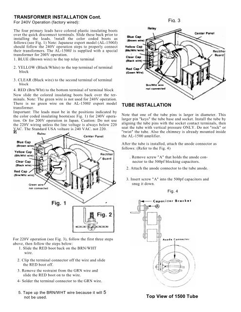
TRANSFORMER INST<strong>AL</strong>LATION Cont.<br />
For 240V Operation (factory wired):<br />
Fig. 3<br />
The four primary leads have colored plastic insulating boots<br />
over the quick disconnect terminals. Slide these back prior to<br />
installing the leads. !nstall the color coded boots as<br />
follows:(see Fig. 1) Note: Japanese export model (<strong>AL</strong>-<strong>1500</strong>J)<br />
should follow the 240V operation steps to properly connect<br />
their transformers. The <strong>AL</strong>-<strong>1500</strong>J is supplied with a special<br />
transformer for 200V operation.<br />
1. BLUE (Brown wire) to the top relay terminal<br />
2. YELLOW (Black/White) to the top terminal of terminal<br />
block<br />
3. CLEAR (Black wire) to the second terminal of terminal<br />
block<br />
4. RED (Brn/Wht) to the bottom terminal of terminal block<br />
Now slide the colored insulating boots back over the terminals.<br />
Note: The green wire is not used for 240V operation.<br />
There is no green wire on the <strong>AL</strong>-<strong>1500</strong>J export model<br />
transformer.<br />
Important: The leads must be in the positions indicated by<br />
the color coded insulating boots(see Fig. 1) for 240V operation.<br />
Or for 200V operation in Japan. Caution: Do not use<br />
the 220V wiring unless the line voltage is always below 220<br />
VAC. The Standard USA voltage is 240 VAC, not 220.<br />
TUBE INST<strong>AL</strong>LATION<br />
Note that one of the tube pins is larger in diameter. This<br />
larger pin "keys" the tube base and socket. Install the tube by<br />
aligning the tube pins with the socket contact terminals, then<br />
seat the tube with vertical pressure ONLY. Do not "rock" or<br />
"twist" the tube. Also the chimney is already mounted inside<br />
the <strong>AL</strong>-<strong>1500</strong> amplifier.<br />
After the tube is installed, attach the anode connector as<br />
follows: (Refer to the Fig. 4)<br />
. Remove screw "A" that holds the anode connector<br />
to the 500pf blocking capacitors.<br />
2. Attach the anode connector to the tube anode.<br />
3. Insert screw "A" into the 500pf capacitors and<br />
snug it down.<br />
Fig. 4<br />
For 220V operation (see Fig. 3), follow the first three steps<br />
above, then follow the steps below:<br />
1. Slide the RED boot back on the BRN/WHT<br />
wire.<br />
2. Clip the terminal connector off the wire and slide<br />
the RED boot off.<br />
3. Remove the restraint from the GRN wire and<br />
slide the RED boot on to the wire.<br />
4- Solder the terminal connector to the GRN wire.<br />
5. Tape up the BRN/WHT wire because it will 5<br />
not be used.<br />
Top View of <strong>1500</strong> Tube