AMERITRON AL-1500 FULL POWER LINEAR AMPLIFIER - QRZCQ
AMERITRON AL-1500 FULL POWER LINEAR AMPLIFIER - QRZCQ
AMERITRON AL-1500 FULL POWER LINEAR AMPLIFIER - QRZCQ

You also want an ePaper? Increase the reach of your titles
YUMPU automatically turns print PDFs into web optimized ePapers that Google loves.
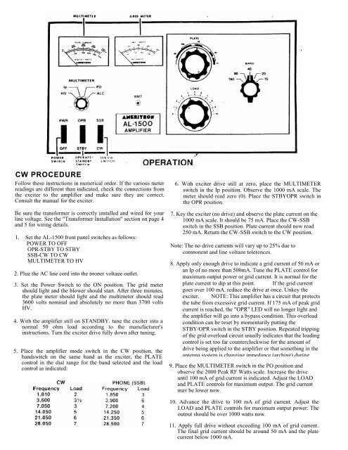
CW PROCEDURE<br />
Follow these instructions in numerical order. If the various meter<br />
readings are different than indicated, check the connections from<br />
the exciter to the amplifier and make sure they are correct.<br />
Consult the manual for the exciter.<br />
Be sure the transformer is correctly installed and wired for your<br />
line voltage. See the "Transformer Installation" section on page 4<br />
and 5 for wiring details.<br />
1. Set the <strong>AL</strong>-<strong>1500</strong> front panel switches as follows:<br />
<strong>POWER</strong> TO OFF<br />
OPR-STBY TO STBY<br />
SSB-CW TO CW<br />
MULTIMETER TO HV<br />
2. Plug the AC line cord into the proper voltage outlet.<br />
3. Set the Power Switch to the ON position. The grid meter<br />
should light and the blower should start. After three minutes,<br />
the plate meter should light and the multimeter should read<br />
3600 volts nominal and absolutely no more than 3700 volts<br />
HV.<br />
4. With the amplifier still on STANDBY. tune the exciter into a<br />
normal 50 ohm load according to the manufacturer's<br />
instructions. Turn the exciter drive fully down after tuning.<br />
5. Place the amplifier mode switch in the CW position, the<br />
bandswitch on the same band as the exciter, the PLATE<br />
control in the dial range for the band selected and the load<br />
control as indicated:<br />
6. With exciter drive still at zero, place the MULTIMETER<br />
switch in the Ip position. Observe the 1000 mA scale. The<br />
meter should read zero (0). Place the STBYOPR switch in<br />
the OPR position.<br />
7. Key the exciter (no drive) and observe the plate current on the<br />
1000 mA scale. It should be 75 mA. Place the CW-SSB<br />
switch in the SSB position. Plate current should now read<br />
250 mA. Return the CW-SSB switch to the CW position.<br />
Note: The no drive currents will vary up to 25% due to<br />
component and line voltage tolerences.<br />
8. Apply only enough drive to indicate a grid current of 50 mA or<br />
an Ip of no more than 500mA. Tune the PLATE control for<br />
maximum output power or grid current. It is normal for the<br />
plate current to dip at this point. If the grid current<br />
goes over 100 mA. reduce the drive at once. Unkey the<br />
exciter. NOTE: This amplifier has a circuit that protects<br />
the tube from excessive grid current. If 175 mA of peak grid<br />
current is reached, the "OPR" LED will no longer light and<br />
the amplifier will go into a bypass condition. This overload<br />
condition can be reset by momentarily putting the<br />
STBY/OPR switch in the STBY position. Repeated tripping<br />
of the grid overload circuit usually indicates that the loading<br />
control is set too far counterclockwise for the amount of<br />
drive being applied to the amplifier or that something in the<br />
antenna system is changing impedance (arching) during<br />
9. Place the MULTIMETER switch in the PO position and<br />
observe the 2000 Peak RF Watts scale. Increase the drive<br />
until 100 mA of grid current is indicated. Adjust the LOAD<br />
and PLATE controls for maximum output. The grid current<br />
may be lower now.<br />
10. Advance the drive to 100 mA of grid current. Adjust the<br />
LOAD and PLATE controls for maximum output power. The<br />
output should be over 1000 watts now.<br />
11. Apply full drive without exceeding 100 mA of grid current.<br />
The final grid current should be around 50 mA and the plate<br />
current below 1000 mA.