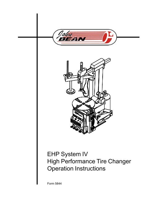
EHP System IV High Performance Tire Changer Operation Instructions
EHP System IV High Performance Tire Changer Operation Instructions
EHP System IV High Performance Tire Changer Operation Instructions
You also want an ePaper? Increase the reach of your titles
YUMPU automatically turns print PDFs into web optimized ePapers that Google loves.
<strong>EHP</strong> <strong>System</strong> <strong>IV</strong><br />
<strong>High</strong> <strong>Performance</strong> <strong>Tire</strong> <strong>Changer</strong><br />
<strong>Operation</strong> <strong>Instructions</strong><br />
Form 5844
(BLANK PAGE)
COPYRIGHT NOTICE<br />
The information contained in this document is property of John Bean,<br />
division of Snap-on Incorporated. It or any of the information contained<br />
within shall not be used, copied, or reproduced without express written<br />
consent of John Bean or its holding company.<br />
TRADEMARK NOTICE<br />
John Bean is a trademark of Snap-on Incorporated.
(BLANK PAGE)
<strong>EHP</strong> <strong>System</strong> <strong>IV</strong> <strong>Operation</strong> <strong>Instructions</strong><br />
SAFETY INFORMATION<br />
For your safety, read this manual thoroughly<br />
before operating the <strong>EHP</strong> <strong>System</strong> <strong>IV</strong> <strong>Tire</strong> <strong>Changer</strong><br />
The <strong>System</strong> <strong>IV</strong> Series <strong>Tire</strong> <strong>Changer</strong>s are intended for use by properly trained automotive<br />
technicians. The safety messages presented in this section and throughout the<br />
manual are reminders to the operator to exercise extreme care when changing tires<br />
with these products.<br />
There are many variations in procedures, techniques, tools, and parts for changing tires,<br />
as well as the skill of the individual doing the work. Because of the vast number of wheel<br />
and tire applications and potential uses of the product, the manufacturer cannot possibly<br />
anticipate or provide advice or safety messages to cover every situation. It is the automotive<br />
technician's responsibility to be knowledgeable of the wheels and tires being<br />
changed. It is essential to use proper service methods and change tires in an appropriate<br />
and acceptable manner that does not endanger your safety, the safety of others in<br />
the work area or the equipment or vehicle being serviced.<br />
It is assumed that, prior to using the <strong>System</strong> <strong>IV</strong> Series <strong>Tire</strong> <strong>Changer</strong>s, the operator has<br />
a thorough understanding of the wheels and tires being changed. In addition, it is assumed<br />
he has a thorough knowledge of the operation and safety features of the rack, lift,<br />
or floor jack being utilized, and has the proper hand and power tools necessary to service<br />
the vehicle in a safe manner.<br />
Before using the <strong>System</strong> <strong>IV</strong> Series <strong>Tire</strong> <strong>Changer</strong>s, always refer to and follow the safety<br />
messages and service procedures provided by the manufacturers of the equipment<br />
being used and the vehicle being serviced.<br />
IMPORTANT !! SAVE THESE INSTRUCTIONS -- DO NOT DISCARD !!<br />
- Page 5 -
SAFETY INSTRUCTIONS<br />
IMPORTANT!! SAVE THESE INSTRUCTIONS<br />
Overinflated tires or rims mounted on the wrong sized rims can explode producing<br />
hazardous flying debris.<br />
• Read Operator’s Manual before using this <strong>Tire</strong> <strong>Changer</strong>.<br />
• Never mount tire on rim with different sized diameter.<br />
• Never exceed maximum inflation pressure listed on tire sidewall.<br />
• Always use safety restraint arm to hold wheel in place while<br />
inflating.<br />
• Always use attached air hose to inflate tires.<br />
Exploding tires can cause death or serious injury.<br />
Risk of electrical shock.<br />
• Do not operate equipment with a damaged power cord or if the<br />
equipment has been dropped or damaged, until it has been<br />
examined by a qualified service person.<br />
• If an extension cord is necessary, a cord with a current rating equal<br />
to or greater than that of the equipment should be used. Cords<br />
rated for less current than the equipment can overheat.<br />
• Unplug equipment from electrical outlet when not in use. Never<br />
use the cord to pull the plug from the outlet. Grasp plug and pull to<br />
disconnect.<br />
• Do not expose the equipment to rain. Do not use on wet surfaces.<br />
• Plug unit into correct power supply.<br />
• Do not remove or bypass grounding pin.<br />
Contact with high voltages can cause death or serious injury.<br />
Risk of electrical shock. <strong>High</strong> voltages are present within the base unit.<br />
• There are no user serviceable items within the unit.<br />
• Service on the unit must be performed by qualified personnel.<br />
• Do not open any part of the base cabinet.<br />
• Turn power switch off and unplug the unit before servicing.<br />
Contact with high voltages can cause death or serious injury.<br />
- Page 6 -
<strong>EHP</strong> <strong>System</strong> <strong>IV</strong> <strong>Operation</strong> <strong>Instructions</strong><br />
Warning !<br />
Risk of crushing. Stand clear of bead breaker arm during operation.<br />
• Read and understand the operation instructions before using this<br />
tire changer.<br />
• Become familiar with all controls before proceeding with operation.<br />
• Stand away from the bead breaker arm when in operation.<br />
• Apply air to breaker in bursts if necessary to control arm depth.<br />
• Keep all persons clear of tire changer.<br />
Contact with moving parts could cause injury.<br />
Warning !<br />
Risk of pinching or crushing hands and fingers when mounting and demounting.<br />
• Read and understand the operation instructions before using this<br />
tire changer.<br />
• Keep hands and fingers clear of rim edge during demounting and<br />
mounting process.<br />
• Keep hands and fingers clear of mount/demount head during operation.<br />
• Keep hands and other body parts away from moving surfaces.<br />
• Do not use tools other than those supplied with tire changer.<br />
• Do not bypass any safety features.<br />
• Use proper tire lubricate to prevent tire binding.<br />
Contact with moving parts could cause injury.<br />
Risk of eye injury. Flying debris, dirt, and fluids may be discharged during bead<br />
seating and inflation process.<br />
• Remove any debris from tire tread, wheel surfaces.<br />
• Remove excess tire lubricant before inflating.<br />
• Wear approved safety glasses during mount and demount<br />
procedures.<br />
Debris, dirt, and fluids can cause serious eye injury.<br />
Risk of injury. Tools may break or slip if improperly used or maintained.<br />
• Read and understand the operation instructions before using this<br />
tire changer.<br />
• Use only the mount-demount tire tool supplied with the tire changer.<br />
• Frequently inspect, clean, and lubricate (if recommended) where<br />
designated.<br />
• Follow procedures when instructed in this manual.<br />
Tools that break or slip can cause injury.<br />
IMPORTANT !! SAVE THESE INSTRUCTIONS -- DO NOT DISCARD !!<br />
- Page 7 -
<strong>Tire</strong>s and Rims that are not the same diameter are mismatched.<br />
• NEVER attempt to mount or inflate any tire and rim that are mismatched.<br />
• ALWAYS check to see that tire and rim diameters are the same.<br />
A mismatched tire and rim will explode causing death or serious personal injury<br />
Over-pressurized tires can explode causing flying debris.<br />
• Read and understand Operator’s Manual before operating.<br />
• Keep bystanders away from work area.<br />
• ALWAYS wear Safety Goggles.<br />
• ALWAYS check to see that <strong>Tire</strong> and Rim diameters are the same.<br />
• NEVER attempt to mount or inflate any <strong>Tire</strong> and Rim with different<br />
diameters.<br />
• Inspect tires, NEVER inflate tires that are damaged, rotten or worn.<br />
• NEVER inflate ‘Split Rim Wheels’ on this tire changer, remove them and<br />
use only an approved safety inflation cage designed for this purpose.<br />
• Lock turntable Clamp on inside of rim before attempting to inflate tire.<br />
• Use approved tire bead lubricant before removing or installing tire on<br />
rim.<br />
• ALWAYS position the “Safety Restraint Arm” over the wheel to hold it<br />
to the turntable while inflating if so equipped.<br />
• If a tire explodes on this tire changer, STOP using it until the "Safety<br />
Restraint Arm" has been replaced, which must be done even if no<br />
damage is seen.<br />
• NEVER place head or body over a tire during inflation process.<br />
• Use short bursts of air to seat tire beads, check tire air pressure<br />
frequently. NEVER exceed tire manufacturer’s pressure limits.<br />
• NEVER attempt to bypass or alter the built in air pressure limiter. Only<br />
inflate tire with air hose supplied with tire changer. NEVER use shop<br />
inflation hose to inflate a tire.<br />
• <strong>Tire</strong> <strong>Changer</strong> must be anchored to concrete floor if equipped with a<br />
“Safety Restraint Arm”<br />
Exploding <strong>Tire</strong>s can cause serious injury.<br />
- Page 8 -
<strong>EHP</strong> <strong>System</strong> <strong>IV</strong> <strong>Operation</strong> <strong>Instructions</strong><br />
TABLE OF CONTENTS<br />
SAFETY STATEMENTS Page 5-8<br />
TABLE OF CONTENTS Page 9<br />
1.0 Introduction Page 10<br />
1.1 Specifications and Features Page 10<br />
1.2 Nomenclature Page 10<br />
1.3 Dimensions of the Machine Page 12<br />
1.4 Standard Accessories Page 12<br />
1.5 Optional Accessories Page 13<br />
1.6 General Precautions Page 14<br />
2.0 Installation Page 14<br />
2.1 Electric Installation Page 14<br />
2.2 Bead Breaker Installation Page 15<br />
2.3 Air Installation Page 15<br />
3.0 Controls Page 16<br />
4.0 Mounting and Demounting-precautions Page 17<br />
4.1 Demounting Tubeless <strong>Tire</strong>s Page 17<br />
4.2 Mounting Tubeless <strong>Tire</strong>s Page 20<br />
4.3 Inflating Tubeless <strong>Tire</strong>s Page 21<br />
5.0 Demounting Tube Type <strong>Tire</strong>s Page 23<br />
5.1 Mounting Tube Type <strong>Tire</strong>s Page 23<br />
5.2 Inflating Tube Type <strong>Tire</strong>s Page 24<br />
6.0 Mounting/Demounting Motorcycle <strong>Tire</strong>s Page 24<br />
7.0 Maintenance Page 25<br />
8.0 Optional Bead Assist Attachment Page 26<br />
- Page 9 -
1.0 INTRODUCTION<br />
Congratulations on purchasing the JBC <strong>System</strong> <strong>IV</strong> electric/air<br />
tire changer. This tire changer is designed for<br />
ease of operation, safe handling of rims, reliability and<br />
speed. This combination of features means more profit<br />
and added versatility for your shop, enabling you to work<br />
with aluminum or magnesium alloy wheels without damaging<br />
customer’s rims. With a minimum of maintenance<br />
and care your JBC <strong>System</strong> <strong>IV</strong> <strong>Tire</strong> <strong>Changer</strong> will provide<br />
many years of trouble-free operation.<br />
Please read this manual thoroughly before operating the<br />
unit. <strong>Instructions</strong> on use, maintenance and operational requirements<br />
of the machine are covered in this manual.<br />
Jaw and Air<br />
Jet Detail<br />
7<br />
8<br />
15<br />
1.1 SPECIFICATIONS<br />
<strong>Operation</strong> temperature range +41/+122 F (+5/50 C)<br />
<strong>Tire</strong> changers for car, light commercial vehicle and motorcycle<br />
tires designed for one-piece rims.<br />
<strong>System</strong> <strong>IV</strong> Series<br />
Shipping Weight - <strong>System</strong> <strong>IV</strong><br />
517 lbs.<br />
8996 567 lbs.<br />
8996inr<br />
597 lbs.<br />
Rim Clamping Capacity-outside: 10" to 20"(254-<br />
508mm)<br />
Rim Clamping Capacity-inside: 12" to 22"(305-<br />
559mm)<br />
Maximum Rim Width:<br />
15" (381mm)<br />
Maximum <strong>Tire</strong> Diameter:<br />
40" (1016mm)<br />
Bead Breaker Force:<br />
3,300 lbs. @ 150 PSI<br />
Bead Breaker Opening:* ADJ. (2.5"-12.5") or (3" - 15")<br />
Air Pressure Required: 110 to 170 psi (8-12bar)<br />
Electrical Requirements:(air/elect models)<br />
110V 60Hz Single Phase<br />
*<strong>Tire</strong> profile may effect machines ability to completely break<br />
bead. Specification given is opening between breaker pad<br />
and breaker blade only.<br />
1.2 NOMENCLATURE<br />
Before installing and using the JBC <strong>System</strong> <strong>IV</strong> <strong>Tire</strong><br />
<strong>Changer</strong> it is suggested that you become familiar with<br />
the nomenclature of the machine’s components.<br />
1 Vertical slide<br />
2 Diameter Slide<br />
3 Diameter Lock Button<br />
4 Diameter Slide Handle<br />
5 Mount/demount head<br />
6 Tower or column<br />
7 Turntable<br />
8 Clamping Jaws<br />
9 Bead breaker arm<br />
10 Bead breaker blade<br />
11 Bead breaker pads<br />
12 Foot pedal controls<br />
13 Inflation gauge<br />
14 Bead seater/inflator pedal<br />
15 Inflation jets<br />
16 Safety restraint arm<br />
(Optaional)<br />
17 Safety restraint positioning knob<br />
(Optional)<br />
18 Inflation hose<br />
19 Lube bottle<br />
20 Mount/Demount Tool<br />
21 Safety Restraint Arm Anti-rotation Lock<br />
827a<br />
Figure 1<br />
- Page 10 -
<strong>EHP</strong> <strong>System</strong> <strong>IV</strong> <strong>Operation</strong> <strong>Instructions</strong><br />
TURNTABLE & CABINET FEATURES<br />
<strong>System</strong> <strong>IV</strong> Series<br />
TURNTABLE AND CABINET FEATURES<br />
RACING/HIGH PERFORMANCE MODIFICATIONS<br />
* ROUND OVERSIZED 22" TURNTABLE PLATFORM -<br />
Provides superior support and capacity to change up to 22” high<br />
performance tires.<br />
* INTEGRATED BEAD SEATING JETS - Air inflation jets are<br />
integrated into the turntable clamping jaws to insure full bead<br />
seating force directly into the tire cavity regardless of tire diameter.<br />
* TWIN CYLINDER CLAMPING POWER - Two 3" clamping<br />
cylinders provide uniform clamping pressure throughout the<br />
stroke (regardless of rim sizes) as well as providing 25% more<br />
clamping power than most single clamping cylinder tire changers.<br />
Additionally two smaller cylinders reduce the critical turntable to<br />
cabinet distance, reducing the stress on the transmission.<br />
* HIGH TORQUE 1HP MOTOR -<br />
Industrial strength high torque turntable drive motor ensures<br />
smooth, quiet operation.<br />
* PNEUMATIC OPERATED DOUBLE LOCK - Unique design<br />
provides the ultimate in mount/demount head rigidity by<br />
pneumatically locking the arm at two separate points, with the<br />
push of a thumb activated button.<br />
* INCREASED TOWER STRENGTH - Square Mount/Demount<br />
tower has increased steel thickness (.24"), increased horizontal<br />
arm (2"x2 3/4") to minimize any flex while mounting high<br />
performance tires.<br />
SAFETY RESTRAINT ARM<br />
* WHEEL CLAMPS<br />
UNIQUE SIX POINT CONTACT CLAMPS<br />
Provide better gripping capability regardless of dirt and<br />
moisture.<br />
REDUCED ANGLE CLAMPS<br />
Increases clamping contact area with rim insuring no<br />
slippage when clamping from outside.<br />
NYLON INSERT SOFT TOUCH CLAMPS<br />
Single sided nylon insert in the clamping jaws provides nonmetal<br />
touch in critical customer visible areas.<br />
* WATER SEPARATOR AND AUTOMATIC OILER<br />
Lubricates all air used for machine operation, does not lubricate<br />
air used for tire inflation, as do some competitive models.<br />
* INCOMING AIR PRESSURE GAUGE<br />
Ergonomically located air gauge allows easy monitoring of<br />
incoming air pressure<br />
* INTEGRATED PRESSURE LIMITER<br />
Integrated safety pressure limiter stops air flow once pressure<br />
has reached 55 PSI preventing accidental tire over-inflation.<br />
MOUNT/DEMOUNT ARM ASSEMBLY<br />
* PNEUMATIC TOWER TILT - Mount/Demount tower automatically<br />
tilts back with the single push of a foot operated pedal.<br />
* TIRE/RIM ASSEMBLY RESTRAINT - Safety Restraint Arm<br />
positively restrains tire and rim assembly to the tire machine<br />
during the inflation process reducing potential for injury caused by<br />
the unlikely event of catastrophic tire or rim failure.<br />
* SIMPLE SWING ARM DESIGN - SRA arm easily swings to<br />
the left when not in use allowing the technician to quickly and<br />
safely perform the inflation process without disrupting the tire<br />
changing procedure.<br />
* GRAVITY LOCK - SRA lock mechanism operates without any<br />
mechanical cam system eliminating the possibility of system<br />
deterioration or mis-adjustment from mechanical wear.<br />
* POSITIONING SAFETY INTERLOCK SWITCH - Integrated<br />
switch insures that SRA arm is centered on the tire/rim assembly<br />
before the inflation process can begin.<br />
* ANTI-ROTATION LOCK - Prevents SRA from rotating during<br />
inflation process.<br />
CONSTRUCTION DESIGNED FOR DURABILITY<br />
* RUST PROOF VALVES AND CYLINDERS - Critical bead<br />
breaking cylinder is lined with rustproof polyfiber liner for years of<br />
rust free operation.<br />
* LIFETIME LUBRICATED POLYMER VALVES - Critical<br />
footvalves fabricated from glass/fiber self lubricating material<br />
providing years of maintenance free operation.<br />
* ADJUSTABLE SLIDEWAY - Unique adjustable mount/<br />
demount shaft slideway allows for easy operator adjustment to<br />
compensate for any cumulative wear in the slideway causing<br />
mount/demount head movement.<br />
* NON-SCRATCH NYLON INSERT - Integrated into the mount/<br />
demount head is a scratch resistent nylon insert protecting<br />
against accidental rim contact.<br />
- Page 11 -
1.3 MACHINE DIMENSIONS<br />
1.4 STANDARD ACCESSORIES<br />
87111 - Mount /Demount Tool (Fig.3)<br />
Figure 3<br />
294<br />
Inflation Gauge is mounted on the Inflation Column.<br />
(Not shown)<br />
Air Filter and Air Lubricator, (Fig.4)<br />
Figure 2<br />
827<br />
Figure 4<br />
539<br />
Incoming Air Pressure Gauge<br />
Located on the air filter and the air lubricator<br />
Lubrication Bottle<br />
Lubrication Applicator<br />
Replacement Mount/Demount Head Inserts (4)<br />
- Page 12 -
<strong>EHP</strong> <strong>System</strong> <strong>IV</strong> <strong>Operation</strong> <strong>Instructions</strong><br />
1.5 OPTIONAL ACCESSORIES<br />
66735 - Bead Holding Clamp (Fig.7)<br />
87435 - Motorcycle Adapter (Fig.5)<br />
Figure 7<br />
315<br />
Figure 5<br />
320<br />
87436 - 8" Wheel Adapter (Fig.6)<br />
Figure 6<br />
316<br />
87434 - Mount/Demount Assisant (Fig 5a)<br />
Figure 5a<br />
- Page 13 -
1.6 GENERAL CAUTIONS<br />
A. DURING THE USE AND MAINTENANCE OF THE MA-<br />
CHINE IT IS MANDATORY TO COMPLY WITH ALL LAWS<br />
AND REGULATIONS FOR ACCIDENT PREVENTION.<br />
B. THE ELECTRICAL POWER SOURCE MUST HAVE A<br />
GROUND CABLE AND THE GROUND CABLE OF THE<br />
MACHINE MUST BE CONNECTED TO THE GROUND<br />
CABLE OF THE POWER SOURCE.<br />
C. BEFORE ANY MAINTENANCE OR REPAIRS ARE AC-<br />
COMPLISHED THE MACHINE MUST BE DISCON-<br />
NECTED FROM THE AIR AND ELECTRICAL SUPPLY.<br />
D. NEVER WEAR TIES, CHAINS OR OTHER LOOSE<br />
ARTICLES WHEN USING, MAINTAINING OR REPAIR-<br />
ING THE MACHINE. LONG HAIR IS ALSO DANGER-<br />
OUS AND SHOULD BE KEPT UNDER A HAT. THE<br />
USER MUST WEAR PROPER SAFETY ATTIRE -<br />
GLOVES, SAFETY SHOES AND GLASSES.<br />
2.1 ELECTRICAL INSTALLATION<br />
BUILDING ELECTRICAL INSTALLATION MUST<br />
BE MADE BY A LICENSED ELECTRICIAN.<br />
Check that the electrical specifications of the power source<br />
are the same of the machine. The machine uses 110v, 60<br />
hz, single phase 20 amp source. Electric specifications<br />
are clearly marked on a label at the rear of the machine.<br />
FAILURE TO PROVIDE PROPER ELECTRICAL<br />
SUPPLY AND GROUNDING WILL CREATE A<br />
SHOCK HAZARD TO THE OPERATOR.<br />
2.0 INSTALLATION<br />
Your new JBC <strong>System</strong> <strong>IV</strong> <strong>Tire</strong> <strong>Changer</strong> requires a simple<br />
installation procedure requiring only a few moments.<br />
Follow these instructions carefully to insure proper and<br />
safe operation.<br />
The <strong>Tire</strong> <strong>Changer</strong> is delivered mounted to a wooden skid.<br />
Remove tire changer from its mounts carefully, taking care<br />
to avoid any back strain.<br />
Place <strong>Changer</strong> where proper operation will be unobstructed<br />
to all sides. Install the machine in a covered and dry place.<br />
2.0.1 Models with SRA attached (Optional)<br />
Once placed in the desired location the tire changer must be<br />
bolted to the floor using only the rear two mounting holes.<br />
Mounting anchors are provided with those machines with a<br />
Safety Restraint Arm. Concrete must be a minimum of four<br />
inches commercial grade, 3500-4000 PSI, with a cure time of<br />
at least 28 days. Steel mesh reinforced.<br />
<strong>Tire</strong> <strong>Changer</strong> must be anchored to concrete floor<br />
if equipped with a “Safety Restraint Arm”<br />
540<br />
- Page 14 -
<strong>EHP</strong> <strong>System</strong> <strong>IV</strong> <strong>Operation</strong> <strong>Instructions</strong><br />
2.2 BEAD BREAKER INSTALLATION<br />
The side mounted Bead Breaker is shipped from the<br />
factory dismounted for a more compact shipping package.<br />
A. Cut the plastic tie strap which secures the Breaker<br />
Arm to the cabinet pivot.<br />
B. Remove the “C” clip from the top of the pivot pin, slip<br />
the pin out of the hole.<br />
C. Place the Breaker Arm into position and insert the<br />
pivot pin through the top and bottom holes.<br />
D. Replace the “C” clip retainer onto the pivot pin.<br />
E. Locate the spring located at the rear of the pivot mount.<br />
Place the free end of the spring onto the “ear” located on<br />
the Breaker Arm just forward of the pivot.<br />
WARNING!<br />
BEFORE CONNECTING THE<br />
MACHINE TO THE AIR SUP-<br />
PLY BE SURE ALL PERSON-<br />
NEL ARE CLEAR OF THE MA-<br />
CHINE AND NO ITEMS ARE<br />
LEFT ON THE TURNTABLE.<br />
B. It is recommended that an air valve shut-off be installed<br />
between the shop air supply and the tire changer<br />
in case of air line or filter failure.<br />
C. Should you install any optional accessories, please<br />
refer to the relevant instructions.<br />
D. Ensure the functional ability of the air lubricator by<br />
ensuring that the glass site bowl is filled with air lubricant.<br />
TIP: You may tie a small rope or cord onto the free end of<br />
the spring, run the cord through the hole. Pull the spring<br />
end toward the ear and loop free end over.<br />
2.3 AIR INSTALLATION<br />
THE AIR INSTALLATION MUST BE MADE ONLY<br />
BY QUALIFIED PERSONNEL.<br />
EXCESS<strong>IV</strong>E AIR PRESSURE CAN SERIOUSLY<br />
INJURE PERSONNEL AND DAMAGE THE MA-<br />
CHINE.<br />
Ensure that the line pressure is within the limits required<br />
by the machine. If the pressure exceeds 170 psi (12 bar) it<br />
is mandatory to install a pressure regulator before the air<br />
inlet of the machine.<br />
If the air pressure is lower than the minimum required of<br />
110 psi (8 bar) the clamping power of the turntable and the<br />
bead breaker power may be insufficient for certain tires<br />
and substantially reduces tire changer performance.<br />
It is suggested that the air supply be equipped with a water<br />
separator/dryer type modification for maximum performance.<br />
After ensuring all the above proceed as follows:<br />
A. Connect the machine to the air supply with a rubber<br />
hose (rated for the pressure) with an internal diameter<br />
of no less than 1/2" (12.5mm).<br />
- Page 15 -
E<br />
A<br />
541a<br />
542a<br />
WARNING!<br />
WATCH YOUR FINGERS AND LEGS!<br />
C<br />
B<br />
D<br />
3.0 CONTROLS<br />
Figure 8<br />
Before operating the machine, take time to familiarize yourself<br />
with the operation and function of all controls.<br />
A<br />
B<br />
C<br />
D<br />
E<br />
Press down the first pedal from the left, the tower will<br />
pneumatically move into position. Press again to make<br />
the tower move back.<br />
Press down and release the second pedal (1) from<br />
the left: the jaws of the turntable will retract. Do it<br />
again: the jaws will expand. If you press the pedal<br />
prior to the end of the stroke and release, the jaws<br />
may be stopped in any position.<br />
Open the bead breaker arm. Press down and hold<br />
the second pedal (2) from the left: by doing this you<br />
operate the bead breaker blade and the arm will move<br />
towards the machine. Release the pedal: the bead<br />
breaker blade will retract.<br />
Press down the first pedal (3) from the right: the turntable<br />
turns clockwise. Placing your foot under the<br />
pedal and lift, the turntable turns counterclockwise.<br />
Press the diameter lock button to lock the diameter<br />
slide, press again to release the diameter slide.<br />
554<br />
F<br />
G<br />
Press bead-seater pedal on left side of the machine<br />
(6 ) half way down: air will come out from inflation<br />
hose end.<br />
Press bead-seater pedal (6) all the way down swiftly<br />
to get air blast from the inflator jets in the clamping<br />
jaws. Air simultaneously comes out of inflator hose.<br />
ATTENTION!<br />
WHEN OPERATING THE BEAD SEATER IT IS MANDA-<br />
TORY TO WEAR SAFETY GLASSES TO PROTECT<br />
EYES.<br />
Standard Model with SRA<br />
H Safety Restraint Arm (7) swings to center of the turntable.<br />
I Lift upward on the restraint positioning knob (8) to position<br />
over tire/wheel assembly for inflation, at the<br />
same time push down on the Anti-rotation Lock Arm<br />
to release lock. (9) You may now swing the safety restraint<br />
arm to position on the center of the wheel.<br />
Lower the restraint until the rubber pad on the restraint<br />
disc is resting on the rim center. The SRA is a gravity<br />
lock which will automatically lock if any force other<br />
than the restraint position knob is lifted. You are now<br />
ready for the inflation process.<br />
NOTE: the air supply will not function until the safety<br />
arm is centered over the turntable.<br />
- Page 16 -
<strong>EHP</strong> <strong>System</strong> <strong>IV</strong> <strong>Operation</strong> <strong>Instructions</strong><br />
4.0 MOUNTING AND DEMOUNTING PRECAUTIONS<br />
IMPORTANT!<br />
BEFORE MOUNTING A TIRE ON A RIM, PAY ATTEN-<br />
TION TO THE FOLLOWING:<br />
A. THE RIM MUST BE CLEAN AND IN GOOD CONDI-<br />
TION: IF NECESSARY CLEAN IT AFTER REMOVING<br />
ALL WHEEL-WEIGHTS INCLUDING ‘TAPE WEIGHTS’<br />
INSIDE THE RIM.<br />
B. THE TIRE MUST BE CLEAN AND DRY, WITHOUT<br />
ANY DAMAGE TO THE BEAD.<br />
C. REPLACE THE RUBBER VALVE STEM WITH A NEW<br />
ONE OR REPLACE THE ‘O’ RING IF THE VALVE STEM<br />
IS MADE OF METAL.<br />
D. IF THE TIRE REQUIRES A TUBE, MAKE SURE THE<br />
TUBE IS DRY AND IN GOOD CONDITION.<br />
E. LUBRICATION IS NECESSARY TO MOUNT THE<br />
TIRE CORRECTLY AND GET A PROPER CENTERING.<br />
BE SURE YOU ARE USING APPROVED LUBRICANT<br />
ONLY.<br />
F. MAKE SURE THE TIRE IS THE CORRECT SIZE FOR<br />
THE RIM.<br />
4.1 DEMOUNTING TUBELESS TIRES<br />
A. Remove all wheel-weights from the rim. Remove the<br />
valve stem or valve stem core and deflate the tire (Fig.11).<br />
Pay extra attention during this operation as it is easy to<br />
mistakenly keep your foot on the bead breaking pedal too<br />
long. This could potentially result in bead or rim damage<br />
(Fig.12)<br />
Fig.12<br />
NOTICE !<br />
ON CHEVROLET CORVETTE WHEELS WITH THE OP-<br />
TIONAL LOW PRESSURE SENSOR INSTALLED,<br />
BREAK THE BEAD AT 90 DEGREES OFFSET FROM<br />
THE VALVE STEM. DAMAGE TO THE WHEEL AND/OR<br />
SENSOR WILL RESULT IF THE BEAD IS BROKEN AT<br />
ANY OTHER POINT ON THE RIM.<br />
536<br />
C. Set the rim clamps to the proper position: retract clamps<br />
to clamp the wheel from the outside and expand clamps<br />
to clamp from the inside.<br />
When clamping small wheels (14" or smaller) from the<br />
outside, set the clamps at a diameter nearly equal to the<br />
rim diameter, before placing the wheel on the clamps. This<br />
will help avoid the possibility of pinching the tire as the<br />
clamps retract.<br />
NOTICE !<br />
TO MINIMIZE THE RISK OF SCRATCHING ALLOY OR<br />
CLEAR COATED RIMS, THESE RIMS SHOULD BE<br />
CLAMPED FROM THE OUTSIDE.<br />
Fig.11<br />
535a<br />
B. Break both beads.<br />
Hold open the Bead Breaker, roll the tire/rim into the<br />
Breaker area (Fig. 12). Ensure that the <strong>Tire</strong>/rim assembly<br />
is against the rubber breaker pads on the side of the machine.<br />
Make certain that the bead breaker blade is not<br />
over the top of any portion of the rim. Now activate the<br />
bead breaker pedal. As soon as the bead dislodges from<br />
the rim, release the breaker foot pedal. It may be necessary<br />
to rotate the tire 90 degrees and repeat the above<br />
procedure to dislodge all beads.<br />
- Page 17 -
D. Liberally lubricate both beads. Place the wheel WITH<br />
DROP CENTER UP (Fig.13a) on the turntable, and clamp<br />
in position. Hold the tire and wheel down while clamping.<br />
1/16”<br />
Fig.14<br />
332<br />
Fig.13 Fig. 13a<br />
E. Gently position the mount/demount head in contact with<br />
rim edge, now manually push the lock button and lock it<br />
into place. The tool automatically moves vertically up and<br />
away from the rim edge.<br />
331<br />
NOTE:<br />
EVERY MACHINE IS EQUIPPED WITH SEVERAL RE-<br />
PLACEMENT PLASTIC INSERTS (INSIDE STANDARD<br />
EQUIPMENT PACK). THE PLASTIC INSERTS WILL<br />
HELP AVOID DAMAGE FROM ACCIDENTAL CONTACT<br />
BETWEEN THE MOUNT/DEMOUNT HEAD AND THE<br />
RIM. THE PLASTIC INSERTS WILL NEED TO BE PE-<br />
RIODICALLY REPLACED.<br />
MAINTENANCE NOTE:<br />
IF THE MOUNT/DEMOUNT HEAD NYLON INSERTS<br />
ARE WEARING OUT PREMATURELY, THE CAUSE IS<br />
THE OPERATORS FAILURE TO CORRECTLY SET THE<br />
SWING ARM ADJUSTMENT KNOB, CAUSING THE IN-<br />
SERT TO INCORRECTLY CONTACT THE RIM.<br />
NOTE:<br />
ONCE THE MOUNT/DEMOUNT HEAD IS POSITIONED<br />
PROPERLY, IDENTICAL WHEELS MAY BE CHANGED<br />
WITHOUT HAVING TO RESET THE HEAD.<br />
F. Insert the mount/demount tool under the bead and over<br />
the support of the mount/demount head. Lift the bead onto<br />
the mount/demount head. To make this operation easier,<br />
insure that the bead of the tire, directly across from the<br />
mount/demount head, is in the drop center of the wheel.<br />
Push the tire into the drop center with your hand or bead<br />
depressor tool if necessary.<br />
If desired, the mount/demount tool can be removed after<br />
lifting the bead onto the mount/demount head (Fig.15), or<br />
you may remove the tool after the bead has been removed.<br />
- Page 18 -
<strong>EHP</strong> <strong>System</strong> <strong>IV</strong> <strong>Operation</strong> <strong>Instructions</strong><br />
333<br />
Fig.15<br />
G. Rotate the turntable clockwise (pedal down) and, at the<br />
same time, push down on the tire sidewall to move the<br />
bead into the drop center of the rim (Fig.16).<br />
335<br />
Fig.17<br />
334<br />
Fig.16<br />
H. Repeat the process for removing the lower bead.<br />
This time, lift the bead opposite to the mount/demount head<br />
to keep it in the drop center (Fig.17).<br />
Move the swing arm aside and remove the tire.<br />
- Page 19 -
4.2 MOUNTING TUBELESS TIRES<br />
A. Clean entire rim surface (Fig.18).<br />
NOTICE!<br />
THESE LUBRICATION OPERATIONS ARE<br />
NECESSARY TO MOUNT THE TIRE CORRECTLY<br />
AND GET A PROPER CENTERING ON THE RIM. BE<br />
SURE YOU ARE USING APPROVED LUBRICANT<br />
ONLY.<br />
Fig.18<br />
Liberally lubricate both beads of the tire with approved tire<br />
lubricant (Fig.19).<br />
336<br />
DANGER!! Keep hands<br />
and fingers clear of<br />
mount-demount head<br />
during operation.<br />
Fig.19<br />
337<br />
- Page 20 -
<strong>EHP</strong> <strong>System</strong> <strong>IV</strong> <strong>Operation</strong> <strong>Instructions</strong><br />
NOTICE!<br />
SOME TIRES HAVE A COLOR DOT THAT IS TO BE<br />
KEPT ON THE OUTSIDE OF THE WHEEL AND IS TO<br />
BE ALIGNED WITH THE VALVE STEM. IF THIS IS THE<br />
CASE BE SURE TO ATTAIN PROPER ALIGNMENT<br />
PRIOR TO TIRE INFLATION.<br />
B. Lock the rim to the turntable and rotate it so that the<br />
valve is at the 2 o’clock position. Place the tire to be<br />
mounted on the rim. Move the mount/demount head toward<br />
it s forward working position. (Fig. 20) Engage the<br />
lower bead OVER the mount/demount head and UNDER<br />
the mounting finger of the mount/demount head (Fig.20).<br />
Turn the wheel clockwise (right pedal down) while simultaneously<br />
pushing the tire down into the drop center, opposite<br />
to the mount/demount head.<br />
4.3 INFLATION OF TUBELESS TIRES.<br />
Make sure that both beads are properly lubricated.<br />
BEAD SEATING IS THE MOST DANGEROUS PART OF<br />
MOUNTING A TIRE.<br />
NEVER STAND OVER TIRE WHEN ATTEMPTING TO<br />
SEAT BEADS OR DURING INFLATION<br />
IT IS POSSIBLE TO INCORRECTLY MOUNT TIRES<br />
THAT ARE 1/2" SMALLER IN DIAMETER THAN THE<br />
RIM THAT THEY ARE MOUNTED ON. WHILE THESE<br />
BEADS WILL SEAL, IT IS IMPOSSIBLE TO GET THEM<br />
TO SEAT IN THEIR PROPER POSITION.<br />
EXPLOSION OF A TIRE MAY CAUSE SEVERE INJURY<br />
OR DEATH.<br />
Inflate tire according to manufacturers recommendations.<br />
SAFETY RESTRAINT ARM MUST BE IN PLACE PRIOR<br />
TO ATTEMPTING BEAD SEATING OR INFLATION.<br />
338<br />
NEVER EXCEED THE MAXIMUM PRESSURE AL-<br />
LOWED BY THE TIRE MANUFACTURER.<br />
THE RIM MUST BE UNCLAMPED WHEN INFLATING<br />
BUT ONLY AFTER THE BEADS HAVE BEEN SEATED.<br />
Fig.20<br />
C. Mount the upper bead following the directions in section<br />
B. With low profile tires the bead holding clamp (option<br />
66735 Fig.21) can help to prevent the top bead from<br />
prematurely seating during the mounting cycle.<br />
NOTE: Bead Holding Clamp must be removed prior to<br />
coming full circle and impacting the mount/demount head.<br />
THE OPERATOR MUST STAND CLEAR FROM THE<br />
WHEEL WHEN INFLATING, AND PRESSURE MUST BE<br />
MONITORED FREQUENTLY TO AVOID OVER INFLA-<br />
TION.<br />
BEFORE INFLATING A TIRE, CHECK THE CONDITION<br />
OF THE TIRE AND THE RIM.<br />
Due to unusual configurations or the stacking of tires the<br />
inflation process may be difficult. To assist with this problem<br />
the JBC <strong>System</strong> <strong>IV</strong> <strong>Tire</strong> <strong>Changer</strong>s are equipped<br />
with bead seater jets integrated into the table top.<br />
To utilize the bead seater proceed as follows:<br />
A. Position the safety restraint arm over center of wheel<br />
assembly. The safety arm is lifted upward by grasping the<br />
safety restraint position knob and lifting upward while simultaneously<br />
depressing the anti-rotation lock arm. Swing<br />
safety arm assembly so the circular retainer is centered<br />
over the rim. Note that air pressure to the inflation hose<br />
will not flow until the arm is centered over the rim.<br />
B. If possible lock the wheel from inside. Outside locking<br />
reduces efficiency.<br />
Fig.21<br />
39<br />
C. Connect the inflation hose to the valve stem.<br />
- Page 21 -
D. Lift the tire with both hands so that the upper bead is<br />
sealed to the rim edge (Fig.21).<br />
NEVER STAND OVER TIRE WHEN<br />
ATTEMPTING TO SEAT BEADS OR DURING<br />
INFLATION<br />
Fig.22<br />
340<br />
E. Press the inflation pedal down swiftly to the end of its<br />
travel to activate the bead seater jets. (#6 Fig.10)<br />
The top bead is already sealed by the lifting motion. Therefore,<br />
the air from the bead seater jets will enter the tire<br />
impacting on the top sidewall and rebound into the bottom<br />
sidewall driving it into place and creating a seal.<br />
WHEN OPERATING THE BEAD SEATER, ALWAYS<br />
WEAR SAFETY GLASSES TO AVOID INJURY TO EYES.<br />
F. Install valve core, if removed. Complete inflation to manufacturers<br />
suggested pressure. Never exceed pressure<br />
listed on tire sidewall.<br />
- Page 22 -
<strong>EHP</strong> <strong>System</strong> <strong>IV</strong> <strong>Operation</strong> <strong>Instructions</strong><br />
5.0 DEMOUNTING TUBE-TYPE TIRES<br />
A. For breaking the bead operate as described for the<br />
tubeless tires in section 4.1.A to 4.1.F.<br />
C. Inflate the tube slightly: if held with the index finger it<br />
should bend a little (Fig.24).<br />
In this case the valve is part of the tube.<br />
NOTICE!<br />
BE CAREFUL NOT TO DAMAGE THE TUBE DURING<br />
THE BEAD-BREAKING OPERATION. THE VALVE<br />
SHOULD BE OPPOSITE TO THE BLADE OF THE BEAD<br />
BREAKER.<br />
B. To demount the first bead, place the valve at 2 o’clock<br />
position.<br />
NOTICE!<br />
BE CAREFUL NOT TO CATCH THE TUBE WITH THE<br />
MOUNT/DEMOUNT TOOL, WHEN LIFTING THE BEAD<br />
ON THE MOUNTING FINGER.<br />
After demounting the first bead carefully, remove the tube<br />
before demounting the second bead, as described in section<br />
4.1.<br />
5.1 MOUNTING TUBE-TYPE TIRES<br />
A. Perform steps described in section 4.2.A.<br />
DO NOT lubricate the tube. Talc can be used to assist<br />
with tire positioning if necessary.<br />
B. Confirm that the tube is the correct size for the tire to<br />
be mounted. (Fig.23).<br />
Fig.24<br />
D. Mount the first bead as described in section 4.2.B.<br />
Put the tube inside the tire and connect the inflation air line<br />
to the tube valve to hold the tube in place. (Fig.25). Mount<br />
the top bead following the directions above.<br />
342<br />
Fig.23<br />
341<br />
Fig.25<br />
343<br />
- Page 23 -
5.2 INFLATING TUBE-TYPE TIRES.<br />
Make sure that both beads are properly lubricated.<br />
BEAD SEATING IS THE MOST DANGEROUS PART OF<br />
MOUNTING A TIRE.<br />
NEVER STAND OVER TIRE WHEN ATTEMPTING TO<br />
SEAT BEADS OR DURING INFLATION<br />
IT IS POSSIBLE TO MOUNT TIRES THAT ARE 1/2"<br />
SMALLER IN DIAMETER THAN THE RIM THAT THEY<br />
ARE MOUNTED ON. WHILE THESE BEADS WILL SEAL,<br />
IT IS IMPOSSIBLE TO GET THEM TO SEAT IN THEIR<br />
PROPER POSITION.<br />
EXPLOSION OF A TIRE MAY CAUSE SEVERE INJURY<br />
OR DEATH.<br />
SAFETY RESTRAINT ARM MUST BE IN PLACE PRIOR<br />
TO ATTEMPTING BEAD SEATING OR INFLATION.<br />
NEVER EXCEED THE MAXIMUM PRESSURE<br />
ALLOWED BY THE TIRE MANUFACTURER.<br />
THE RIM MUST BE UNCLAMPED WHEN INFLATING<br />
BUT ONLY AFTER THE BEADS HAVE BEEN SEATED.<br />
THE OPERATOR MUST STAND CLEAR FROM THE<br />
WHEEL WHEN INFLATING, AND PRESSURE MUST BE<br />
MONITORED FREQUENTLY TO AVOID OVER<br />
INFLATION.<br />
BEFORE INFLATING A TIRE, CHECK THE CONDITION<br />
OF THE TIRE AND THE RIM.<br />
To inflate the tire unlock the rim and start inflating while<br />
pressing the valve towards the inside (this is necessary to<br />
avoid air pockets forming between tube and the tire)<br />
(Fig.26).<br />
Ensure that the tire is correctly centered on the rim and<br />
complete inflation.<br />
6.0 MOUNTING AND DEMOUNTING MOTORCYCLE<br />
TIRES<br />
To mount and demount motorcycle tires it is necessary to<br />
utilize the optional four motorcycle adaptors (part number<br />
87435).<br />
The bead-breaking, mounting and demounting technique<br />
is the same as per the car, tubeless or tube-type tires.<br />
NOTICE!<br />
MOTORCYCLE RIMS MUST ALWAYS BE CLAMPED<br />
FROM THE OUTSIDE. SUPPLY AIR PRESSURE TO<br />
THE CHANGER MUST NOT EXCEED 110 PSI (8 BAR)<br />
WHEN CLAMPING MOTORCYCLE RIMS.<br />
Fig.26<br />
537<br />
- Page 24 -
<strong>EHP</strong> <strong>System</strong> <strong>IV</strong> <strong>Operation</strong> <strong>Instructions</strong><br />
7.0 MAINTENANCE<br />
BEFORE STARTING ANY MAINTENANCE OPERATION<br />
ENSURE THAT THE MACHINE IS DISCONNECTED<br />
FROM THE AIR AND ELECTRIC SUPPLY.<br />
A. Periodically clean the vertical hexagonal rod with<br />
nonflammable liquid detergent.<br />
After this immediately lubricate with a light lubricating oil<br />
(Fig.27).<br />
F. Periodically wash all plastic parts with cold water and<br />
soap or window cleaner.<br />
G. Check the bead breaker pads. Replace if worn.<br />
H. Discharge water from air filter every day.!! (Do this by<br />
turning the knob “B” clockwise and upward. Water will<br />
automatically be discharged.) (see ‘B’ at Fig.29).<br />
I. Check the automatic air lubricator oil level weekly.<br />
When adding oil to the lubricator, disconnect the air<br />
supply first, remove the fill screw ‘A’, and add oil as<br />
needed. Make sure seals are in place when replacing<br />
the cap.<br />
Fig.27<br />
B. Periodically clean all moving metal parts and lubricate<br />
with oil.<br />
C. Weekly clean the teeth of the clamps (1) with a wire<br />
brush, check the nylon clamping jaw insert and (2) replace<br />
if worn (Fig.28).<br />
Automatic Air Oiler<br />
Fig.29<br />
Water Separator Filter<br />
NOTICE!<br />
USE ONLY OILS FOR AIR DEVICES, DO NOT USE<br />
BRAKE FLUID OR OTHER NON SUGGESTED<br />
LUBRICANTS.<br />
553<br />
Suggested oils for the filter/lubricator unit:<br />
1 2<br />
TAMOIL: WHITE MINERAL OIL 15<br />
SHELL: ONDINA OIL 15<br />
BP: ENERGOL WT 3<br />
TOTAL: LOBELIA SB 15<br />
ESSO: MARCOL 82<br />
7.0 MOVING THE MACHINE<br />
Do not move the machine by attaching onto the bead<br />
assistant device. Attach sling to the turntable if to be<br />
lifted by hoist.<br />
Fig.28<br />
D. Inspect and replace as necessary the plastic mount/<br />
demount head insert. The insert is held in place by a<br />
small roll pin. Drive the pin out with a punch, replace<br />
after new insert is installed.<br />
E. Lubricate piston rods of turntable air cylinders with<br />
oil as needed.<br />
8.0 PUTTING THE MACHINE OUT OF SERVICE<br />
In case the machine is not be used for a long period of<br />
time (6 months or more) it is necessary to disconnected<br />
air and power service, protect all parts that may<br />
be damaged from environmental intrusion.<br />
When putting the machine back in operation, check the<br />
condition of all previously protected parts, and check<br />
for correct functioning of all devices before using the<br />
machine again.<br />
- Page 25 -
87434 BEAD ASSIST ATTACHMENT (IF FIELD RETROFITTING NON EQUIPPED UNITS)<br />
1.1 INTRODUCTION<br />
The model 87434 Bead Assist Attachment is intended<br />
to be used to ease the mounting and demounting of<br />
car tires.<br />
The 87434 can be used only in conjunction with<br />
John Bean <strong>System</strong> <strong>IV</strong> Series <strong>Tire</strong> <strong>Changer</strong>s.<br />
The 87434 should be used only as intended and instructed<br />
so within this manual.<br />
Any other use shall be considered as improper and not<br />
reasonable.<br />
In particular, the installation on machines not allowed<br />
can result in hazardous conditions.<br />
The manufacturer shall not be considered liable for<br />
damages caused by improper, wrong or, unreasonable<br />
use.<br />
This manual is a part of the product.<br />
Read carefully all warnings and instructions of this<br />
manual since they provide important information concerning<br />
the safety and maintenance of the 87434 .<br />
1.2 GENERAL SAFETY INSTRUCTIONS<br />
<strong>Operation</strong> of this device should be restricted to only<br />
personnel who are properly trained.<br />
Any deviation or modification of this device or of its<br />
parts or components not previously authorized by the<br />
manufacturer waive the manufacturer from any damage<br />
consequent or related to the above mentioned deviations.<br />
Removing or modifying safety devices or warning labels<br />
of the machine is in violation of safety regulations.<br />
The use of this device is allowed only in locations with<br />
no explosion or fire hazard.<br />
Only original accessories are to be used in conjunction<br />
with this device. Any repair or routine maintenance<br />
items should include only original spare parts<br />
and accessories.<br />
The installation should be performed by qualified personnel<br />
and within respect of the instructions provided<br />
for within this manual.<br />
If a malfunctioning condition is detected, stop using the<br />
machine and call the authorized JBC Representative for<br />
assistance.<br />
The raise-descent speed of the movable column is limited<br />
to 0.2 m/sec to prevent compression hazards.<br />
The lower bead-push device is free to rotate around<br />
the horizontal and vertical axis to prevent entrapping<br />
and compression hazards against the self-centering<br />
chuck of the machine on which the device is being<br />
mounted.<br />
2.0 HANDLING INSTRUCTIONS<br />
ALWAYS WEAR GLOVES WHEN UNCRATING THE<br />
MACHINE TO PREVENT SCRATCHES OR ABRA-<br />
SIONS DUE TO CONTACT WITH PACKING MATERI-<br />
ALS.<br />
The shipping box is mounted in a steady wooden pallet.<br />
The machine should be transported only with an<br />
appropriate lifting device (fork lift) Fig.1.<br />
Uncrating: Pay attention when cutting the banding or<br />
during any other operation which may be hazardous.<br />
After removing the carton check for any visible damage<br />
to the machine and its components, notify the carrier<br />
immediately of any damage.<br />
For installation assistance call your JBC Representative.<br />
2.1 PACKAGING REMOVAL<br />
The material of the packing (plastic bags, polystyrene,<br />
nails, screws, wood etc.) shall not be left behind and<br />
shall not be left at childrens reach since they may be<br />
possible hazards.<br />
Place the above mentioned materials in proper trash<br />
container and dispose following any local regulations.<br />
Figure 1.<br />
Check for possible dangerous conditions during the<br />
operation of the machine. In such a case. Cease operation<br />
immediately.<br />
- Page 26 -
<strong>EHP</strong> <strong>System</strong> <strong>IV</strong> <strong>Operation</strong> <strong>Instructions</strong><br />
3.0 PRE-INSTALLATION INSTRUCTIONS<br />
Check that the machine onto which this device is to be<br />
mounted is installed in work area large enough to<br />
acomodate the additionof this device.<br />
The installation of this device increases the changers<br />
footprint requirment only slightly.<br />
Insure that enough space is left around the machine to<br />
prevent compression or entrapping hazards.<br />
A<br />
Make sure that from the operating position, the operator<br />
can see all the machine and the surrounding area.<br />
The operator shall forbid the presence of non authorized<br />
persons and of objects which may create possible<br />
hazards.<br />
THE AIR INSTALLATION MUST BE MADE ONLY BY<br />
LICENSED PERSONNEL IF LOCAL RESTRICTIONS<br />
APPLY.<br />
Figure 1 - Place template/spacer, mark location and<br />
drill holes.<br />
Ensure that the input line pressure is within the<br />
minumum/maximum limits (110-170psi) required by the<br />
machine.<br />
If air pressure is lower than the minimum required of<br />
110 psi, the force of the device may be insufficient for<br />
certain types of tires.<br />
After checking all the above proceed as follows:<br />
DISCONNECT ELECTRIC AND AIR SUPPLY FROM<br />
THE CHANGER BEFORE INSTALLATION OF THIS<br />
DEVICE.<br />
3.1 INSTALLATION INSTRUCTIONS<br />
A. Place the drilled template/spacer plate “A” as shown<br />
in Figure 1. The square angle must be in contact with<br />
the side wall of the Cabinet and with the reinforcement<br />
welds.<br />
IMPORTANT! THE DRILLED PLATE (“A” FIGURE 1)<br />
MUST BE LEFT AS A SPACER BETWEEN THE DE-<br />
VICE AND THE BEAD BREAKER BEAM.<br />
Bolts, washers and<br />
nuts in four places<br />
2<br />
4<br />
3<br />
1<br />
B. Drill 4 (1/2") holes all the way through the bead<br />
breaker beam using plate “A” as a template.<br />
C. Lift the device with an appropriate lifting device,<br />
(engine hoist, fork lift) and a sling belt of sufficient<br />
capacity - 1100 lbs. Attach the device ( #1 in Figure<br />
2) to the bead breaker beam (#2) with the bolts (#3),<br />
washers (#4) and nuts (#5) supplied.<br />
4<br />
5<br />
Figure 2 - With template/spacer in position, place the<br />
device onto the breaker arm beam. Secure with<br />
supplied hardware.<br />
- Page 27 -
3.1 AIR INSTALLATION<br />
A. Remove the left side panel from the changer.<br />
B. Locate the air hose coming from the oiler side of<br />
the filter/oiler assembly which is mounted on the rear<br />
of the cabinet. See Figure 3 hose #1.<br />
C. Cut the air hose (#1) coming from the air filter/<br />
lubricator and attach “Tee” fitting #2 as shown in Figure<br />
3.<br />
D. Route the air feed hose (#3) from the Bead Assist<br />
Attachment through the same hole in the rear of the<br />
cabinet as hose #1.<br />
E. Attach the hose #3 to the Tee fitting (#2) on hose<br />
#1.<br />
F. Close the side panel of the tire changer and secure<br />
with the lock screw.<br />
4.0 NOMENCLATURE<br />
Before using the 87434 Bead Assist Attachment, it is<br />
suggested that you become familiar with the nomenclature<br />
of components (Figure 4).<br />
1. Raise/Descent control<br />
2. Roller<br />
3. Handle<br />
4. Roller release lever<br />
5. Horizontal arm<br />
6. Lower bead-push device<br />
7. Movable column<br />
8. Mounting column<br />
9. Mounting plate<br />
4.1 CONTROLS<br />
1<br />
Filter/oiler assembly<br />
3<br />
4<br />
1<br />
2<br />
2<br />
5<br />
3<br />
6<br />
7<br />
Figure 3 - Air Installation detail<br />
9<br />
8<br />
Figure 4 - Nomenclature<br />
- Page 28 -
<strong>EHP</strong> <strong>System</strong> <strong>IV</strong> <strong>Operation</strong> <strong>Instructions</strong><br />
Before operating the machine ensure that you have well<br />
understood the operation and function of all controls.<br />
A. Press the raise button (#2 Fig. 4) to raise the column<br />
and consequently the roller and the lower beadpush<br />
device.<br />
B. Press the descent button (#1 Fig. 4) to lower the<br />
mobile column and consequently the roller and the lower<br />
bead-push device.<br />
C. Operate the unlock lever to release the roller arm.<br />
Slide the horizontal arm all the way to the rear and<br />
swing the roller arm to bring the roller at rest position.<br />
Repeat the opposite operations to bring the roller into<br />
the working position.<br />
5.0 USE AS A DEMOUNTING ASSISTANT<br />
A. Position the roller approximately. 3/4” (2 cm ) from<br />
the rim edge. Press the descent button to depress the<br />
side wall of the tire to ease the insertion of the tire iron<br />
(Figure - 5). Raise the column and move the roller to<br />
rest position. Demount the first bead as described in<br />
the tire changer operator’s manual.<br />
B. Loser the column, position the lower bead-push device<br />
next to the lower rim edge. Hold the handle firmly,<br />
press the raise button and at the same time rotate the<br />
turntable (Figure 6). This operation allows to loosen the<br />
bead if this is stuck and helps lifting the tire.<br />
NOTE:<br />
A CERTAIN EFFORT ON THE HANDLE OF THE<br />
Figure 6 -<br />
LOWER BEAD-PUSH DEVICE IN A RADIAL DIREC-<br />
TION IS NORMAL TO COUNTER THE ACTION OF THE<br />
TURNTABLE THAT PUSHES THE DEVICE OFF CEN-<br />
TER WHEN ROTATING.<br />
NOTE:<br />
THE LOWER BEAD-PUSH DEVICE CANNOT BE<br />
LOCKED BECAUSE OF SAFETY REASONS.<br />
5.1 USE AS A MOUNTING ASSISTANT<br />
A. Mount the lower bead.<br />
B. Position the roller as shown in Figure 5. During the<br />
mounting operation the roller pressure helps keeping<br />
the bead in the drop center. Move the roller to rest<br />
position.<br />
NOTE:<br />
The Lower bead-push device is not designed to<br />
break the lower bead. Beads should be broken<br />
with the side mounted breaker prior to demountremount.<br />
The lower bead-push device is designed<br />
to assist the demount operation by holding the tire<br />
up while demounting the lower bead<br />
Figure 5 -<br />
- Page 29 -
(BLANK PAGE)
(BLANK PAGE)
USA<br />
John Bean<br />
309 Exchange Avenue<br />
Conway, Arkansas 72032<br />
Tel.: (800) 362-8326 or (501) 450-1500<br />
Fax: (501) 450-1585<br />
Notice: The information contained in this document is subject to change without notice. John Bean<br />
makes no warranty with regard to this material. John Bean shall not be liable for errors contained<br />
herein or for incidental consequential damages in connection with furnishings, performance, or use of<br />
this material.<br />
This document contains proprietary information which is protected by copyright and patents. All rights<br />
are reserved. No part of this document may be photocopied, reproduced, or translated without prior<br />
written consent of John Bean or its holding company.<br />
is a trademark of John Bean and Snap-on Incorporated<br />
Form 5844...02/20/02...wdc...copyright 2002 Snapon Technologies....<br />
Printed in the USA


