

EEAC321A - Snap-on Equipment
EEAC321A - Snap-on Equipment
EEAC321A - Snap-on Equipment

You also want an ePaper? Increase the reach of your titles
YUMPU automatically turns print PDFs into web optimized ePapers that Google loves.
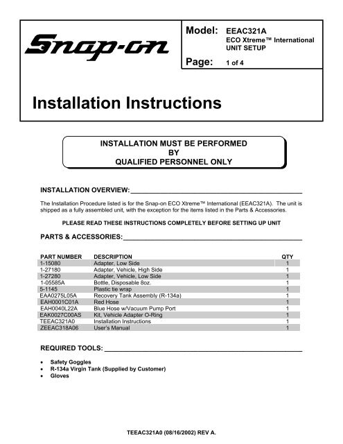
Model: <str<strong>on</strong>g>EEAC321A</str<strong>on</strong>g><br />
ECO Xtreme Internati<strong>on</strong>al<br />
UNIT SETUP<br />
Page: 1 of 4<br />
Installati<strong>on</strong> Instructi<strong>on</strong>s<br />
INSTALLATION MUST BE PERFORMED<br />
BY<br />
QUALIFIED PERSONNEL ONLY<br />
INSTALLATION OVERVIEW:______________________________________________<br />
The Installati<strong>on</strong> Procedure listed is for the <str<strong>on</strong>g>Snap</str<strong>on</strong>g>-<strong>on</strong> ECO Xtreme Internati<strong>on</strong>al (<str<strong>on</strong>g>EEAC321A</str<strong>on</strong>g>). The unit is<br />
shipped as a fully assembled unit, with the excepti<strong>on</strong> for the items listed in the Parts & Accessories.<br />
PLEASE READ THESE INSTRUCTIONS COMPLETELY BEFORE SETTING UP UNIT<br />
PARTS & ACCESSORIES:________________________________________________<br />
PART NUMBER DESCRIPTION QTY<br />
1-15080 Adapter, Low Side 1<br />
1-27180 Adapter, Vehicle, High Side 1<br />
1-27280 Adapter, Vehicle, Low Side 1<br />
1-05585A Bottle, Disposable 8oz. 1<br />
5-1145 Plastic tie wrap 1<br />
EAA0275L05A Recovery Tank Assembly (R-134a) 1<br />
EAH0001C01A Red Hose 1<br />
EAH0040L22A Blue Hose w/Vacuum Pump Port 1<br />
EAK0027C00AS Kit, Vehicle Adapter O-Ring 1<br />
T<str<strong>on</strong>g>EEAC321A</str<strong>on</strong>g>0 Installati<strong>on</strong> Instructi<strong>on</strong>s 1<br />
ZEEAC318A06 User’s Manual 1<br />
REQUIRED TOOLS: _____________________________________________________<br />
• Safety Goggles<br />
• R-134a Virgin Tank (Supplied by Customer)<br />
• Gloves<br />
T<str<strong>on</strong>g>EEAC321A</str<strong>on</strong>g>0 (08/16/2002) REV A.
Page 2 of 4<br />
!<br />
THIS UNIT MUST BE PLUGGED INTO A PROPER AC OUTLET FOR UNIT<br />
TO OPERATE CORRECTLY. REFER TO THE UNIT ID PLATE LOCATED<br />
ON BACK OF UNIT. EXTENSION CORDS ARE NOT RECOMMENDED,<br />
BUT IF AN EXTENSION CORD MUST BE USED, USE A CORD THAT IS<br />
LESS THAN 50 FEET WITH A 16 AWG, OR ABOVE 50 FEET AND LESS<br />
THAN 100 FEET WITH A 14 AWG.<br />
!<br />
USE STANDARD REFRIGERANT HANDLING<br />
SAFETY PROCEDURES WHEN PERFORMING INSTALLATION<br />
ALWAYS WEAR SAFETY GOGGLES, DON’T SPILL OR TOUCH LIQUID<br />
REFRIGERANT, AVOID FLAMES, AND EXCESSIVE HEAT. USE ONLY IN<br />
WELL VENTILATED AREA.<br />
PARTS & ACCESSORIES SETUP__________________________________________<br />
1. Remove the Blue and Red Hoses from the box, al<strong>on</strong>g with the plastic-tie-wrap. Remember to<br />
OIL the seals <strong>on</strong> each end of the hoses.<br />
2. C<strong>on</strong>nect the high (red) and low (blue) couplers to their respective hoses. Rotate coupler knobs<br />
fully CCW (closed).<br />
3. Route both hoses in-between the master filter bracket and the hose that c<strong>on</strong>nects to the filter.<br />
4. Attach other end of the (red) hose to upper, red labeled (high side) port <strong>on</strong> the back panel of the<br />
Eco Xtreme unit.<br />
5. Attach other end of the blue hose to lower, blue labeled (low side) port <strong>on</strong> the back panel of the<br />
Eco Xtreme unit.<br />
6. The plastic-tie wrap will be used later, to secure the hoses to the master filter bracket. (Page 4,<br />
line 12).<br />
7. Install plastic oil bottle (1-05585A) to the white cap mounted in the fr<strong>on</strong>t of the unit.<br />
8. Remove the User's Manual from the box. Hand this item to the Owner or Manager.<br />
9. Remove Recovery Tank (EAA0275L05A) from its box. Remove cardboard wrap from Recovery<br />
Tank and set <strong>on</strong> floor.<br />
T<str<strong>on</strong>g>EEAC321A</str<strong>on</strong>g>0 (08/16/2002) REV A.
Page 3 of 4<br />
PREPARING RECOVERY TANK: __________________________________________<br />
1. Referring to FIGURE 1, open the BLUE valve <strong>on</strong><br />
Recovery Tank to release ALL COMPRESSED AIR.<br />
2. Gently set the Recovery Tank <strong>on</strong> the scale.<br />
3. Place the strap around the recovery tank.<br />
4. Positi<strong>on</strong> the Temperature Probe between the tank and<br />
the strap.<br />
5. Install the supplied tank adapter 1-15080 <strong>on</strong> the Low<br />
(blue) side of the recovery tank.<br />
6. Attach the blue vehicle hose w/adapter to the Low side<br />
of the tank.<br />
7. Plug AC Cord to a proper AC outlet. And turn-<strong>on</strong> the<br />
unit by the rear panel switch.<br />
FIGURE 1 RECOVERY TANK<br />
NOTE: In the unlikely event, the LCD screen is<br />
unreadable up<strong>on</strong> power up, adjust LCD c<strong>on</strong>trast. Refer to the users manual for c<strong>on</strong>trast<br />
adjustment.<br />
8. Press the Down arrow, Arrow <strong>on</strong> display will be pointing to “VACUUM”.<br />
a. Press .<br />
b. Press the Down arrow until desired amount of vacuum time is displayed.<br />
c. Turn the fr<strong>on</strong>t panel low panel valve to VACUUM.<br />
d. Press Start butt<strong>on</strong>, vacuum pump should turn ON in about 5 sec<strong>on</strong>ds.<br />
9. The low side gauge shows vacuum increasing.<br />
10. M<strong>on</strong>itor low side gauge until a minimum of 25 inches has been reached.<br />
11. Once completed, close the Recovery Tank valve (BLUE). Close the R-134a Coupler.<br />
12. Press EXIT butt<strong>on</strong>. The pump will shut-off.<br />
13. Remove the blue service hose from the tank.<br />
NOTE: Remove the R-134a tank adapter, (1-15080) and place in the storage tray.<br />
14. Identify the three hoses leading from the bottom of the unit. C<strong>on</strong>nect<br />
the yellow hose to the tank purge port. See figure to the right.<br />
Rotate the tank so the valves face towards the rear of the unit.<br />
15. Identify the blue hose leading from the bottom of the unit.<br />
C<strong>on</strong>nect hose with the anti-blowback valve to the blue (liquid) valve.<br />
16. If you are going to c<strong>on</strong>tinue with Gravity refrigerant transfer<br />
(found <strong>on</strong> page 4), leave the red hose disc<strong>on</strong>nected.<br />
Otherwise identify the red hose leading from the bottom of<br />
the unit. C<strong>on</strong>nect hose with the anti-blowback valve to the red (vapor) valve.<br />
17. Open both red and blue valves <strong>on</strong> tank unless c<strong>on</strong>tinuing with Gravity Transfer method.<br />
18. If you are going to c<strong>on</strong>tinue with Gravity refrigerant transfer, do not attach plastic –tie. Using the<br />
plastic-tie wrap (5-1145) route the tie through the hole in the bracket, wrap around the hoses and<br />
tie.<br />
Refer to the users manual for pre-charging tanks.<br />
Refer to next page for first time fast charge.<br />
INSTALLATION COMPLETE<br />
Purge<br />
Port<br />
T<str<strong>on</strong>g>EEAC321A</str<strong>on</strong>g>0 (08/16/2002) REV A.
Page 4 of 4<br />
PRE-CHARGING RECOVERY TANKS USING GRAVITY METHOD:<br />
NOTE: THIS PROCEDURE IS USED TO SETUP THE UNIT FOR CHARGING. RECOVERY TANK<br />
SHOULD HAVE AT LEAST A 25” VACUUM. THIS PROCEDURE IS DONE WHEN<br />
RECOVERY TANK IS ON THE SCALE<br />
1. Plug unit in and turn <strong>on</strong>, go into Charge screen to<br />
m<strong>on</strong>itor tank weight.<br />
2. Be sure Recovery Tank valves (B) are closed and<br />
tank is in vacuum <strong>on</strong> scale. Refer to FIGURE 2.<br />
3. Disc<strong>on</strong>nect the Red hose from the Recovery Tank.<br />
4. Disc<strong>on</strong>nect and Re-Oil both the seals <strong>on</strong> blue hose<br />
(C). C<strong>on</strong>nect the <strong>on</strong>e side of the blue Hose w/<br />
adapter (1-15080) to the Virgin Tank (A).<br />
5. C<strong>on</strong>nect the other end of the blue Hose to the Red<br />
Valve <strong>on</strong> the Recovery Tank (B).<br />
6. Open the Red Valve <strong>on</strong> the Recovery Tank.<br />
7. Raise the Virgin Tank to a higher level than the<br />
Recovery Tank. Invert the Virgin Tank (A) and open<br />
valve.<br />
8. Gravity and vacuum will transfer the liquid refrigerant<br />
to the Recovery Tank faster than recovering it.<br />
NOTE: DO NOT OVER CHARGE TANK. THE<br />
SAFE AMOUNT TO CHARGE IS AROUND 15 LBS.<br />
9. After the desired amount of refrigerant has been<br />
transferred, close valves <strong>on</strong> Virgin Tank first, pause<br />
to allow refrigerant to flow into tank, then close<br />
recovery tank valve. Set Virgin Tank <strong>on</strong> ground<br />
upright.<br />
B<br />
10. Disc<strong>on</strong>nect blue hose, and adapter from both Tanks.<br />
11. Re-Oil seals <strong>on</strong> anti-blow back valve <strong>on</strong> the Red<br />
Hose from unit and c<strong>on</strong>nect to Recovery Tank.<br />
Open both Recovery Tank valves.<br />
FIGURE 2 CHARGING TANK<br />
12. Re-Oil seals <strong>on</strong> red and blue hoses. To c<strong>on</strong>nect the<br />
hoses, route both in-between the master filter bracket and the hose that c<strong>on</strong>nects to the filter.<br />
C<strong>on</strong>nect the open end of the Blue hose to the Low side bulkhead fitting and Red Hose to the high<br />
side bulkhead fitting. Using the plastic-tie wrap route the tie through the hole in the bracket, wrap<br />
around the hoses and tie.<br />
13. Unit is ready to recover and charge refrigerant.<br />
A<br />
C<br />
REMEMBER TO OIL O-RINGS AND SEALS<br />
WHEN ATTACHING HOSES OR FITTINGS<br />
T<str<strong>on</strong>g>EEAC321A</str<strong>on</strong>g>0 (08/16/2002) REV A.


