Torqeedo Ultralight 402
Torqeedo Ultralight 402
Torqeedo Ultralight 402

Create successful ePaper yourself
Turn your PDF publications into a flip-book with our unique Google optimized e-Paper software.
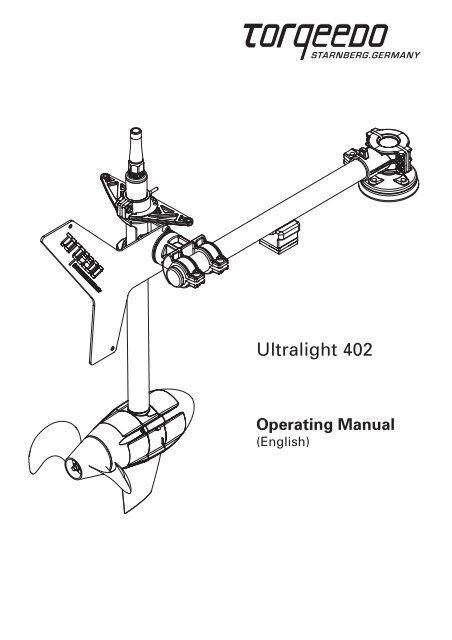
<strong>Ultralight</strong> <strong>402</strong><br />
Operating Manual<br />
(English)
1. Contents<br />
1. Contents<br />
2. Important safety and operating instructions ..................................................................4<br />
3. Introduction .......................................................................................................................6<br />
4. About this operating manual ...........................................................................................7<br />
5. Conformity declaration ....................................................................................................7<br />
6. Warranty conditions .........................................................................................................8<br />
6.1 Extent of warranty ...................................................................................................8<br />
6.2 Warranty process .....................................................................................................9<br />
7. Equipment and operating elements .............................................................................10<br />
7.1 Supply scope ..........................................................................................................10<br />
7.2 Plan of operating elements ...................................................................................11<br />
8. Starting up ......................................................................................................................12<br />
8.1 Attaching and aligning the outboard motor to the kayak ...................................12<br />
8.2 Commissioning the tilting device..........................................................................19<br />
8.3 Attaching the steering ...........................................................................................19<br />
8.4 Connecting the remote throttle control<br />
with the integrated display and magnetic key......................................................20<br />
8.5 Connecting the battery pack .................................................................................20<br />
9. Operation.........................................................................................................................21<br />
9.1 Battery pack and power supply unit......................................................................21<br />
9.2 Tilting device and lock ...........................................................................................22<br />
9.3 Remote throttle with integrated display and magnetic key ...............................23<br />
9.4 Pylon .......................................................................................................................28<br />
9.5 Ideal depth of immersion ......................................................................................29<br />
10. Disassembly ....................................................................................................................29<br />
11. Storage and care instructions .......................................................................................30<br />
11.1 Corrosion protection ..............................................................................................30<br />
11.2 Caring for the battery ............................................................................................30<br />
11.3 Changing the propeller ..........................................................................................31<br />
11.4 Other care instructions ..........................................................................................31<br />
12. Troubleshooting .............................................................................................................32<br />
13. Technical data .................................................................................................................33<br />
14. Disposal instructions ......................................................................................................34<br />
15. Accessories .....................................................................................................................34<br />
16. <strong>Torqeedo</strong> Service Centers...............................................................................................36<br />
Operating Manual <strong>Ultralight</strong> <strong>402</strong><br />
3
2. Important safety and operating instructions<br />
Important safety instructions<br />
<strong>Torqeedo</strong> motors are designed to operate safely and reliably as long as they are used<br />
according to the operating manual. Please read this manual carefully before you start<br />
the motor. Ignoring the instructions in this operating manual can cause damage or<br />
personal injury. <strong>Torqeedo</strong> accepts no liability for any damage caused by actions that<br />
contradict this operating manual.<br />
To ensure safe operation of the motor:<br />
• Familiarize yourself with all the motor controls. For instance, you should be able to<br />
stop the motor quickly if necessary.<br />
• Only allow adults who have been instructed on how to operate the motor or have<br />
read the operating instructions to run it.<br />
• Never operate the motor if someone is in the water close to the boat. Stop the motor<br />
immediately if someone goes overboard.<br />
• Always take a paddle with you on board.<br />
• Check the status and function of the device before each tour.<br />
• Note that the on-board computer does not include changes to currents and wind<br />
conditions in the range calculation. If you are moving with the wind or current the<br />
remaining range is calculated assuming you continue going with the wind or current.<br />
If you change direction or if wind/current change, your remaining range may be<br />
significantly lower. Therefore note the effect that the wind and current along your<br />
route have on your range.<br />
• Never use the motor as a fixing point for your kayak; never use the motor as a handle<br />
for lifting or carrying.<br />
• Do not open the battery casing; protect the battery pack from mechanical damage.<br />
• Do not short circuit the battery pack.<br />
• Avoid submerging the battery pack and remote throttle for longer periods of time.<br />
• If the error code E46 is shown in the display or if you changed the fuse of the battery<br />
the information in the dispaly is not accurate any more. After a complete charge of the<br />
battery, the information dispalyed is reliable again.<br />
• The battery of your <strong>Ultralight</strong> motor has been declared a hazardous item in UN Class 9.<br />
Private transportation is not critical. If shipped by a transport company the relevant<br />
statutory provisions must be observed.<br />
• Keep the magnetic key supplied at least 50 cm / 20 inches away from pacemakers.<br />
• Keep the supplied magnetic key away from magnetic information media (e.g. debit/<br />
credit cards, music cassettes, magnetic tapes etc.). The magnet integrated in the key<br />
has enough strength to make the saved data unusable.<br />
4 Operating Manual <strong>Ultralight</strong> <strong>402</strong>
2. Important safety and operating instructions<br />
Important operating instructions<br />
There follows a selection of the most important instructions for handling <strong>Torqeedo</strong><br />
<strong>Ultralight</strong> motors. Apart from these instructions, please observe the complete operating<br />
instructions to prevent damage to your motor.<br />
• Only run the motor when the propeller is under water. If it is run in the air for longer<br />
periods, the shaft sealant rings that seal the motor to the drive shaft may become<br />
damaged. If the motor is run in air for a longer period, the motor itself can overheat.<br />
• The <strong>Ultralight</strong> product range, the associated remote throttle, battery pack, and all electric,<br />
plug-in connections are protected against dirt and water in line with protection type IP68.<br />
• The <strong>Ultralight</strong> has an integrated protective device that switches the motor off when<br />
it reaches a particular slope (90°). This prevents the propeller from turning if the boat<br />
capsizes or tilts.<br />
• After use, always take the motor out of the water.<br />
• After operation in salty or brackish water, wash all components in fresh water.<br />
• Occasionally use contact spray to care for all electronic contacts. If you use the motor in<br />
salt or brackish water, we recommend applying contact spray once a month.<br />
• You extend the life of your battery if you do not expose it for longer than necessary to<br />
a very hot environment. In order to guarantee that the life of the battery is as long as<br />
possible the battery should be stored for longer period of time (e.g. over the winter) at<br />
around 50 % charge and between 0 °C and +15 °C / +32 °F and +60 °F.<br />
• Only charge the battery at environmental temperatures between 0 °C and +45 °C /<br />
+32 °F and +113 °F.<br />
• Store the motor, battery pack, and remote throttle in the waterproof travel bag only<br />
when dry. If storing the items for longer periods of time in the travel bag, do not close it<br />
so it is airtight.<br />
• Only use the travel bag for transportation not for shipping the motor. The motor stored<br />
in the travel bag must not be adversely affected by heavy objects.<br />
• If the motor has malfunctions an error code is shown on the display. After resolving the<br />
error the motor can be restarted out of the stop position again. In rare cases it may be<br />
necessary to switch the motor off using the “on/off” button. You will find descriptions<br />
and details in Section 9.3.<br />
• Do not disconnect the cable connections when the propeller is turning.<br />
• If you have a problem with your motor, please follow the instructions in this operating<br />
manual for handling warranty claims.<br />
Operating Manual <strong>Ultralight</strong> <strong>402</strong><br />
5
3. Introduction<br />
Dear customer,<br />
We are delighted that you have chosen our motor. Your <strong>Torqeedo</strong> <strong>Ultralight</strong> is state-ofthe-art<br />
in terms of motor, battery, and propeller technology. It has been designed and<br />
manufactured with the utmost care and with a special focus on comfort, user-friendliness,<br />
and safety, and has been extensively tested before delivery.<br />
Please take the time to read this operating manual carefully so that you can use the motor<br />
properly and enjoy it for a long time.<br />
We constantly strive to improve <strong>Torqeedo</strong> products. Should you have any comments<br />
on the design and use of our products, we would be pleased to hear from you. Please<br />
contact our Customer Services if you have any questions on <strong>Torqeedo</strong> products<br />
(service_usa@torqeedo.com or service_international@torqeedo.com).<br />
We hope you will enjoy this product.<br />
Yours,<br />
Friedrich Böbel, PhD Christoph Ballin, PhD Matthias Janzen<br />
Managing Director Managing Director Managing Director<br />
6 Operating Manual <strong>Ultralight</strong> <strong>402</strong>
3. Introduction 4. About this operating manual 5. Conformity declaration<br />
4. About this operating manual<br />
This operating manual will help you use your <strong>Torqeedo</strong> <strong>Ultralight</strong> safely and efficiently. All<br />
information is given according to our latest knowledge. Subject to technical changes.<br />
• Indicates a danger or a procedure that may cause injury<br />
and property damage.<br />
• Indicates a danger or a procedure that may cause property damage.<br />
5. Conformity declaration<br />
We, <strong>Torqeedo</strong> GmbH, with sole responsibility, declare the conformity of the <strong>Ultralight</strong><br />
product range with the following provisions:<br />
Small water vehicles<br />
Electrical systems<br />
Low-voltage direct current (DC) systems<br />
DIN EN ISO 10133:2000<br />
Starnberg, in March 2009<br />
Managing Director‘s signature<br />
The aforementioned company holds the following technical documents available for<br />
viewing:<br />
- Required operating manual<br />
- Plans/software source code (EU authorities only)<br />
- Inspection records (EU authorities only)<br />
- Other technical documentation (EU authorities only)<br />
Operating Manual <strong>Ultralight</strong> <strong>402</strong><br />
7
6. Warranty conditions<br />
6.1 Extent of warranty<br />
<strong>Torqeedo</strong> GmbH, Petersbrunner Straße 3a in D-82319 Starnberg, Germany, guarantees the<br />
final purchaser of a <strong>Torqeedo</strong> outboard motor that the product is free from material and<br />
manufacturing faults during the period stated below. <strong>Torqeedo</strong> will indemnify the final<br />
purchaser for any expense for the repair of a material or manufacturing fault. This indemnification<br />
obligation does not cover the incidental costs of a warranty claim or any other<br />
financial losses (e.g. costs for towing, telecommunications, food, accommodation, loss of<br />
earnings, loss of time etc.).<br />
The warranty ends two years after the date on which the product was delivered to the<br />
final purchaser. Products that are used commercially or by public authorities - even if<br />
only temporarily - are excluded from this two-year warranty. In these cases, the statutory<br />
warranty applies. The right to claim under warranty runs out six months after discovery of<br />
a fault.<br />
<strong>Torqeedo</strong> decides whether faulty parts are repaired or replaced. Distributors and dealers<br />
who repair <strong>Torqeedo</strong> motors have no authority to make legally binding statements on<br />
behalf of <strong>Torqeedo</strong>.<br />
Normal wear and tear and routine servicing are excluded from the warranty.<br />
<strong>Torqeedo</strong> is entitled to refuse a warranty claim if:<br />
• the warranty was not correctly submitted (in particular failure to contact <strong>Torqeedo</strong> before<br />
sending back goods, failure to present a completely filled-in warranty certificate and<br />
proof of purchase, refer to Warranty process),<br />
• the product has been used improperly,<br />
• the safety, operating and care instructions in the manual were not observed,<br />
• the product was in any way altered or modified or parts and accessories were added that<br />
are not expressly permitted or recommended by <strong>Torqeedo</strong>,<br />
• previous services or repairs were not carried out by firms authorized by <strong>Torqeedo</strong>, or<br />
non-original parts were used.<br />
8 Operating Manual <strong>Ultralight</strong> <strong>402</strong>
6. Warranty conditions<br />
As well as the rights arising from this warranty, the customer also has legal warranty claim<br />
rights arising from the purchase contract with the dealer that are not hampered by this<br />
warranty.<br />
6.2 Warranty process<br />
Adhering to the following warranty process is a prerequisite to the satisfaction of any<br />
warranty claims.<br />
Before dispatching any apparently faulty goods, it is imperative to coordinate the delivery<br />
with <strong>Torqeedo</strong> Services. You can contact us by phone, email or mail. The ability to make<br />
contact via the www.torqeedo.com website is being extended successively. You can find<br />
the contact details on the back of this manual. Please understand that we are unable to<br />
deal with products of which we have not been notified and will therefore refuse to accept<br />
delivery.<br />
To check a warranty claim and to process a warranty, we require a completed warranty<br />
certificate as well as proof of purchase.<br />
• The warranty certificate attached to this operating manual must show contact details,<br />
product details, serial number, and a brief description of the problem.<br />
• Proof of purchase must indicate the purchase and the date of purchase (e.g. transaction<br />
receipt.<br />
For returning the motor to the Service Center, we recommend keeping the original <strong>Torqeedo</strong><br />
packaging. If this is no longer available packaging that excludes transport damage<br />
must be used as this is not included in the warranty.<br />
We are available to answer any questions regarding the warranty process - simply use the<br />
details on the back cover.<br />
Operating Manual <strong>Ultralight</strong> <strong>402</strong><br />
9
7. Equipment and operating elements<br />
7.1 Supply scope<br />
The full supply scope of your <strong>Torqeedo</strong> <strong>Ultralight</strong> should include the following parts:<br />
• Motor unit with shaft and connection cable (2 m / 6.5 feet),<br />
universal joint with swing arm, pylon, and propeller<br />
• Boom with clamping device and mounting ball<br />
• Lithium-manganese battery with integrated GPS receiver<br />
• Remote throttle control with integrated display<br />
• Magnetic key<br />
• Assembly set with fixing material, rubber rest, line, elastic cord, lock bolt<br />
and accessories<br />
• Allen key SW5<br />
• Battery pack connection cable – remote throttle (1.5 m / 5 feet)<br />
• Travel bag<br />
• Power unit incl. European power cord, US power cord and UK adapter<br />
• Operating manual<br />
• Warranty certificate<br />
• Packaging<br />
10 Operating Manual <strong>Ultralight</strong> <strong>402</strong>
7. Equipment and operating elements<br />
7.2 Plan of operating elements<br />
Attachment point<br />
for line to manually<br />
tilt the motor<br />
Connection cable<br />
Swing arm<br />
Boom<br />
Elastic cord<br />
Rubber rest<br />
Spacer<br />
Connection to<br />
kayak steering<br />
or fixing the<br />
steering<br />
Attachment point<br />
for “reverse” line<br />
Mounting ball<br />
Shaft<br />
Propeller<br />
Pylon<br />
Fin<br />
Remote throttle control Magnetic key Battery<br />
Operating Manual <strong>Ultralight</strong> <strong>402</strong><br />
11
8. Starting up<br />
8.1 Attaching and aligning the outboard motor to the kayak<br />
1. Prepare the motor for the mounting:<br />
Remove the parts that belong to the <strong>Ultralight</strong> supply scope from the packaging.<br />
Slide the boom with the clamp into the universal joint and clamp it lightly with the<br />
two screws.<br />
1. 2.<br />
2. Select the position where the drive is to be attached to the kayak.<br />
For this please note:<br />
• You need a virtually flat surface on the kayak that is big enough to attach the<br />
mounting ball.<br />
• The motor‘s boom must be horizontal,<br />
i.e. run parallel to the surface of the water.<br />
This ensures that the shaft pipe is vertical<br />
in the water when moving forward.<br />
• To attach the motor to thin-walled touring kayaks it is necessary to use the rubber<br />
rest so that the engine rests on two points on the kayak (mounting ball and rubber<br />
rest). On thicker-walled angling and leisure kayaks it may be possible to fix the motor<br />
only with the aid of the mounting ball without a second resting point.<br />
12 Operating Manual <strong>Ultralight</strong> <strong>402</strong>
8. Starting up<br />
There are three options for connecting the drive to your kayak:<br />
A No connection of the motor to the kayak’s steering system: When travelling with<br />
the motor you must either steer using the paddle or with a rudder that is not<br />
connected to the motor. With this option it is not possible to move in tight circles<br />
using the motor. This type of attachment is recommended if your kayak does not<br />
have a steering system or if you only need the motor for<br />
support or as a back-up on long tours (and do not have<br />
Kayak rudder<br />
to move in tight circles).<br />
Motor<br />
(Steering element fixes)<br />
Rubber<br />
rest<br />
Mounting ball<br />
Mounting at the<br />
tail (no rudder)<br />
Mounting<br />
at the side<br />
B Connecting the motor instead of the rudder to the kayak’s steering system: With<br />
this attachment option you can move your kayak very easily using the motor; but<br />
the rudder is not available when the motor is not in use.<br />
Motor<br />
Mounting ball<br />
Steering system of<br />
the kayak (control<br />
over lines)<br />
• Test whether the steering operates in the desired position before fixing<br />
the mounting ball to the kayak.<br />
Operating Manual <strong>Ultralight</strong> <strong>402</strong><br />
13
C Fixing the motor to the kayak’s steering system in addition to a rudder:<br />
We recommend this attachment option if you want to use a rudder when the motor<br />
is running but also when paddling (while the motor is tilted out of the water).<br />
Connection of the<br />
motor with the rudder<br />
system of the kayak<br />
Steering system of the<br />
kayak<br />
Motor<br />
Rudder<br />
Mounting ball<br />
• Test whether the steering works in the desired position and whether the<br />
kayak’s motor and rudder can be tilted out of the water before fixing<br />
the mounting ball to the kayak.<br />
• The holes for the screw anchors need to have a distance of 2 cm /<br />
0.8 inches to any edge of the kayak.<br />
Mark the four necessary screw positions on the<br />
mounting ball and drill the corresponding holes<br />
(Ø 12 mm / 0.47 inches) into the kayak.<br />
3. Attach the mounting ball to the Kayak.<br />
You have 2 options to attach the mounting ball to the kayak. If the inside of the kayak<br />
hull is accessible we recommend to secure the mounting ball with the screws and nuts<br />
provided in the scope of delivery. If the inside of the kayak hull is not accessible, the<br />
mounting ball can be mounted with the screw anchors provided in the scope of delivery.<br />
A Mounting with screws and nuts:<br />
(recommended if kayak inside is accessible)<br />
Drill four holes in the marked positions<br />
Ø 6.5 mm ( 15 /32 inch).<br />
14 Operating Manual <strong>Ultralight</strong> <strong>402</strong>
8. Starting up<br />
Attach the mounting ball with the screws and nuts provided in the scope of delivery.<br />
To close the boreholes watertight and to compensate for slight curvature of the kayak<br />
surface, use the rubber gasket between the kayak and the mounting ball. To reinforce<br />
the kayak hull under the mounting ball, place the white plastic plate with 8 holes from<br />
the inside between the kayak hull and the nuts.<br />
Screws<br />
Insulating sleeve<br />
Mounting ball<br />
Rubber gasket<br />
Kayak-hull<br />
Plasticplate<br />
Disk<br />
Nut<br />
B Mounting with screw anchors:<br />
(recommended if kayak inside is not accessible)<br />
Drill four holes in the marked positions<br />
Ø 12 mm ( 15 /32 inch).<br />
To ease fixing the screws, apply some<br />
grease or oil to the screw and the screw<br />
anchor.<br />
Operating Manual <strong>Ultralight</strong> <strong>402</strong><br />
15
Take the screws out of the screw anchors.<br />
Place the aluminum key onto one of the screw<br />
anchors. The aluminum key prevents the screw<br />
anchor from turning when the screw is screwed<br />
in.<br />
Place the screw anchor in one of the boreholes.<br />
Please note that the screw anchor needs to fit<br />
easily through the borehole without being<br />
compressed at the sides.<br />
If possible, place the white plastic plate with 8<br />
holes from the inside of the kayak over the screw<br />
anchor. This reinforces the kayak hull at the<br />
mounting point.<br />
If this is not possible, the screw anchors can be<br />
fixed without the plastic plate.<br />
Put a screw through the aluminum key into the<br />
screw anchor. Firmly tighten the screw while<br />
fixing the screw anchor with the aluminum key.<br />
Kayak inside<br />
Note that the screw anchor will expand on the<br />
inside of the kayak. Chose a position for the<br />
wall anchor which allows sufficient space for<br />
this expansion.<br />
16 Operating Manual <strong>Ultralight</strong> <strong>402</strong>
8. Starting up<br />
Unscrew the screw and take the aluminum key<br />
off the screw anchor.<br />
Fix the other screw anchors to the kayak in the<br />
same way.<br />
Place the rubber gasket over the four screw<br />
anchors.<br />
Place the mounting ball onto the rubber gasket.<br />
Insert the plastic insulating sleeves into the<br />
holes of the mounting ball. Insert the four screws<br />
through the insulating sleeves and tigthen them<br />
firmly into the screw anchors.<br />
Operating Manual <strong>Ultralight</strong> <strong>402</strong><br />
17
4. Assemble the drive by clamping the ball<br />
receiver to the mounting ball. For this the<br />
boom must be aligned horizontally to the<br />
water line. When tightening the screws in<br />
the ball clamp, ensure that the gap on both<br />
sides of the clamp is the same distance.<br />
5. If desired, mount the rubber rest on the second motor resting point. Select the desired<br />
location and use the spacers supplied to balance out the height. Attach the rubber rest<br />
in the same fashion used to attach the ball mount by using two screw anchors. Fix<br />
boom to the rubber rest using the elastic cord.<br />
1.<br />
2.<br />
Elastic<br />
cord<br />
Spacer<br />
6. Loosen the screws on the two clamping rings and<br />
position the motor so low that the propeller does not<br />
draw air even at full throttle. Then retighten the two<br />
screws. Ensure that the upper clamp ring is<br />
perpendicular to the propeller axis.<br />
18 Operating Manual <strong>Ultralight</strong> <strong>402</strong>
8. Starting up<br />
• If you are unsure about the position and assembly of your motor contact<br />
your <strong>Torqeedo</strong> dealer.<br />
• Ensure that when tilting the motor the cables are not crimped.<br />
8.2 Commissioning the tilting device<br />
1. Mount a clamp block at the level of the driver’s<br />
seat. Position the clamp block so that it will hold a<br />
line if it is pulled towards the stem of the kayak.<br />
2. Cut the supplied line to 2 x 3 m (10’) and 2 x 0.5 m (2.5’).<br />
Melt the ends e.g. with a lighter.<br />
3. Firmly tie one of the 3 m (10’) lines to the top of the swing arm. Guide the line<br />
through the loop on the ball clamp and fix it in the clamp block. In this way you have<br />
the opportunity to tilt the motor out of the water and to hold it in the tilted position.<br />
1.<br />
2.<br />
4. If you want to use the motor in reverse, mount the second clamp block and guide the<br />
line to the lower end of the pivot arm. This protects the motor from undesired tilting up.<br />
8.3 Attaching the steering<br />
The following steps are only relevant if you want to connect the motor to the kayak’s<br />
steering system.<br />
1. If you want to connect the motor with the kayak’s steering system instead of the<br />
rudder: Fix the lines from the kayak’s steering with the triangular clamp ring at the<br />
upper end of the motor shaft. Extend the lines for the kayak’s steering as far as<br />
necessary, if appropriate you can use the supplied snap hooks to fix the lines<br />
to the clamp ring.<br />
Operating Manual <strong>Ultralight</strong> <strong>402</strong><br />
19
2. If you want to connect the motor to the kayak’s rudder (and via the rudder to the<br />
steering system): Fix the two snap hooks supplied to the short lines. Now connect the<br />
kayak’s rudder with the triangular clamp ring at the upper end of the motor shaft using<br />
the short lines. To do so insert the snap hooks into the<br />
holes in the clamp ring and tie the other end of<br />
the line to the kayak’s rudder. Movements of the<br />
rudder to the left or right should produce the<br />
corresponding steering movements of the motor.<br />
For good steering it is not essential for the<br />
steering movements to be identical.<br />
snap hook<br />
8.4 Connecting the remote throttle control with the integrated display and<br />
magnetic key<br />
Position the remote throttle in the desired position and fix it, e.g. with a RAM mount<br />
holder (M4 thread in the base of the remote throttle control) or a commercial Velcro strip<br />
(not within the scope of supply).<br />
8.5 Connecting the battery pack<br />
1. Insert the battery pack in the desired position in the kayak and fix it if necessary with<br />
straps (not within the scope of supply). When doing so ensure that the top of the<br />
battery (aerial icon) is showing upwards in order to provide the GPS function. Do not<br />
cover the battery pack with metallic objects or those containing metal (e.g. rescue<br />
blankets etc.).<br />
2. Connect the cable from the motor to the battery pack. Ensure that there is a waterproof<br />
bayonet closure that is placed in a particular position and screwed into place.<br />
3. Connect the cable from the remote throttle to the battery pack. Ensure that the<br />
connection is waterproof and screwed into place. It can only be fixed in one position.<br />
20 Operating Manual <strong>Ultralight</strong> <strong>402</strong>
8. Starting up 9. Operation<br />
9. Operation<br />
9.1 Battery pack and power supply unit<br />
The battery pack is equipped with high performance lithium manganese batteries,<br />
so-called LIMA cells. The LIMA cells have a self-discharge of under 1 % per month at<br />
20 °C / 70 °F, have stable cycles, and no memory effect. The lithium battery can be used<br />
at environmental temperatures from -20 °C to +60 °C / -4 °F to +140 °F.<br />
A controller that has several functions to protect and care for your battery is integrated<br />
in the battery pack. The controller, amongst other functions, protects the battery from<br />
fully discharging and overcharging. Therefore you can connect the battery to the charger<br />
without worrying or empty it completely.<br />
During the charging process the controller contained in the battery pack controls the<br />
charging current.<br />
The capacity of the battery pack changes over time. To adjust the capacity indicator we<br />
recommend emptying the fully charged battery completely once a year at average speed.<br />
The battery pack has a 20 A safety fuse. Open the marked cover in the battery’s base to<br />
exchange the fuse. When closing the cover ensure the cover and seal sit properly (label to<br />
the outside).<br />
The charging unit supplied is modified to the controller and charges the <strong>Ultralight</strong>’s<br />
battery pack in approximate 8 hours. When charging at high environmental temperatures<br />
(> 35 °C / > 95 °F) longer charging times may occur as the controller is equipped with a<br />
temperature-dependent charging power off switch which ensures a proper and gentle<br />
charging of the cells. For charging, connect the charging unit with the battery pack and<br />
the power supply. To do so remove the motor cable on the battery pack and use the same<br />
jack for charging.<br />
You can charge the battery pack without the remote throttle being inserted. If the<br />
remote throttle is connected with the battery pack the current charging status in<br />
percent and „charging“ is displayed in the topmost field on the display.<br />
Operating Manual <strong>Ultralight</strong> <strong>402</strong><br />
21
• The battery is protected from water penetration (IP68).<br />
• Use the <strong>Ultralight</strong> battery <strong>402</strong> exclusively with the <strong>Ultralight</strong> <strong>402</strong> outboard<br />
motor.<br />
• Only use the power supply unit supplied or one authorized by <strong>Torqeedo</strong> to<br />
charge the battery pack.<br />
• Only charge the battery at environmental temperatures between 0 °C and<br />
45 °C / +32 °F and +115 °F.<br />
• You extend the lifespan of your battery if you do not expose it to hot<br />
environments for longer than necessary. In order to guarantee the longest<br />
possible lifespan of the battery if you store it for a long time (e.g. over the<br />
winter) it should be charged to around 50 % and stored between 0 °C and<br />
+15 °C / 32 °F and +60 °F.<br />
• Protect the battery pack from mechanical damage. If the housing of the<br />
battery is damaged, do not use the battery.<br />
• Do not short circuit the battery pack.<br />
• Avoid submerging the battery pack for longer periods of time.<br />
• The LIMA battery cells only catch fire if they are exposed to temperatures<br />
over 300 °C / 570 °F. This is an important advantage over other lithiumbased<br />
battery systems. If this should occur try to put the battery in a<br />
location where it will not cause damage. If this is not possible, keep<br />
your distance or cover the battery with sand or other dry, non-flammable<br />
materials.<br />
9.2 Tilting device and lock<br />
For normal movement the fixing lines that go to the lower end of the swing arm should<br />
not be fixed in the clamp block. This enables the motor to tilt up if it gets in contact with<br />
obstacles under water. To move in reverse the lower fixed line must be fixed to the clamp<br />
block.<br />
To tilt the motor the lower fixing line must be released. By pulling the upper line the motor<br />
can be tilted out of the water and fixed in that position using the second clamp block.<br />
The motor does not start if it is tilted up.<br />
22 Operating Manual <strong>Ultralight</strong> <strong>402</strong>
9. Operation<br />
Loosen the upper line to lower the motor.<br />
To lock the steering of the motor insert the lock bolt into the<br />
desired position in the upper clamp ring.<br />
This blocks the steering function.<br />
Lock bolt<br />
• Only tilt the shaft when the lower fixing line is loose.<br />
• For steering the lock bolt must be removed from the upper clamp ring.<br />
9.3 Remote throttle with integrated display and magnetic key<br />
Control the drive power – speed and rotation direction - by adjusting the remote throttle.<br />
Forward movement of the remote throttle means the kayak moves forward, backward<br />
movement of the remote throttle means the kayak moves backwards. Please note that<br />
reverse movement does not have the same output as forward movement. The middle<br />
position corresponds to the stop position.<br />
The remote throttle is equipped with a magnetic key with an on/off function. The motor<br />
only works if you place the magnetic key supplied on the proper location on the remote<br />
throttle control (see drawing). If the magnetic key is removed the motor stops. You can<br />
Operating Manual <strong>Ultralight</strong> <strong>402</strong><br />
23
only start the motor again if you first replace the magnetic key and then move the remote<br />
throttle to the central position (stop position).<br />
Remote throttle control<br />
Magnetic key<br />
The remote throttle is equipped with an on-board computer<br />
with an integrated display and three buttons.<br />
If you press the “on/off” button for 1 second you switch<br />
the motor on. Pressing the button again for 3 seconds<br />
switches the motor off again. You can switch the motor off<br />
in any operating mode. If there is no activity for one hour<br />
the motor switches off automatically. Press the button<br />
again to switch it back on.<br />
Use the “setup” button to set the units for the display. You enter the menu by pressing the<br />
“setup” button for 3 seconds. First you can select the units in which the remaining range<br />
is displayed. By pushing the button in the center of the display you select between kilometers,<br />
miles, nautical miles, and hours. You confirm your selection by pressing “setup”<br />
again. You then enter the speed indicator setting. You can choose between kilometers<br />
per hour, miles per hour, and knots. Again you select the units with the center button and<br />
confirm your selection and leave the “setup“ menu again by pressing the “setup” button<br />
again.<br />
The “cal” label on the center button stands for “calibration”. If the display shows a relevant<br />
error message you can recalibrate the motor with the help of this button. You will find details<br />
on this in the „error codes” table in this section.<br />
24 Operating Manual <strong>Ultralight</strong> <strong>402</strong>
9. Operation<br />
Display in normal operation:<br />
Battery charge status in percent<br />
Remaining range at current speed<br />
Ground speed<br />
Power consumption in Watt<br />
Other indicators:<br />
Drive slowly: Is displayed when the battery capacity is < 20 %.<br />
Charging: Is displayed when charging. Refer to Section 9.1.<br />
: The GPS module integrated into the battery pack searches for<br />
satellite signals to determine the position and speed. If no GPS signal<br />
is received within 5 minutes the display switches in the second field<br />
from “remaining range at current speed” to “remaining time at current<br />
speed”. In addition, a clock icon is displayed. If the remaining duration is<br />
more than 10 hours it is indicated in whole hours. If it is less it is shown<br />
in hours and minutes.<br />
: This icon is displayed if the remote throttle must be placed in the<br />
central position (stop position). This is necessary before starting off.<br />
: Is displayed if the temperature of the engine or battery is too high.<br />
The motor decreases the input power automatically.<br />
Error: If an error occurs the error icon and a two-digit code are displayed<br />
in the bottom field. The code shows the component causing the error<br />
and the error itself. You will find details about the error codes in the<br />
following table.<br />
Operating Manual <strong>Ultralight</strong> <strong>402</strong><br />
25
• For reverse movement the fixing line that goes to the lower end of the<br />
swing arm should be fixed in the clamp block.<br />
• The remaining distance or time at the current speed shown on the<br />
display is a calculated theoretical value. Please be aware that the actual<br />
outstanding range or duration may vary.<br />
• The high thrust of the drive makes it necessary to familiarize yourself<br />
with the characteristics of your <strong>Torqeedo</strong> <strong>Ultralight</strong> <strong>402</strong>. Practice<br />
handling the motor and maneuvering in open water.<br />
• We recommend fixing the magnetic key lanyard to a personal flotation<br />
device (PFD).<br />
• Keep the magnetic key supplied more than 50 cm / 20 inches away<br />
from pacemakers as strong magnets could affect the operation of the<br />
pacemaker.<br />
• Keep the supplied magnetic key away from magnetic information<br />
media (e.g. debit/credit cards, music cassettes, magnetic tapes etc.).<br />
The magnet integrated in the key has enough strength to make the<br />
saved data unusable.<br />
• If the remote throttle’s casing is damaged there is a risk of water<br />
infiltration which could cause the propeller to turn uncontrollably.<br />
For this reason the remote throttle must be exchanged immediately.<br />
The following table contains a list of possible error codes. After resolving the error the<br />
motor can be moved out of the stop position again. In rare cases it may be necessary to<br />
switch the motor off using the “on/off” button on the remote throttle control.<br />
26 Operating Manual <strong>Ultralight</strong> <strong>402</strong>
9. Operation<br />
Fault codes<br />
Display Cause What to do<br />
E02<br />
Stator over-temperature<br />
(engine overheating)<br />
Motor can be used again after a short wait<br />
(about 10 minutes). Contact <strong>Torqeedo</strong> Service.<br />
E03<br />
E04<br />
Motor tilted during<br />
operation<br />
Motor put into operation<br />
while tilted<br />
Motor can be used again after tilting it down<br />
and pressing on/off.<br />
Motor can be restarted from the stop<br />
position after being tilted down.<br />
E05 Motor/propeller blocked Loosen blockage and turn propeller one<br />
revolution by hand.<br />
E06<br />
Voltage in the motor too<br />
low<br />
Low battery charging status. Motor can be<br />
used again slowly from the stop position.<br />
E07 Motor overcurrent Continue at low output. Contact <strong>Torqeedo</strong><br />
Service.<br />
E08 Circuit board overheating Motor can be used again after a short wait<br />
(about 10 minutes). Contact <strong>Torqeedo</strong> Service.<br />
E21<br />
E22<br />
Remote throttle<br />
calibration defective<br />
Magnetic sensor<br />
defective<br />
• Re-calibrate:<br />
Press “cal” button for 10 seconds.<br />
• The display shows “cal up”:<br />
Press remote throttle control forward to<br />
full gas then press the “cal” button.<br />
• The display shows “cal stp”:<br />
Return remote throttle control to central<br />
position then press the “cal” button.<br />
• The display shows “cal dn”:<br />
Press remote throttle control reverse to full<br />
gas then press the “cal” button.<br />
Re-calibrate (refer to E21).<br />
E23 Value range false Re-calibrate (refer to E21).<br />
E30<br />
Motor communication<br />
error<br />
Check the motor cable’s plug-in connection.<br />
Check the motor cable for damage. Check the<br />
fuse at the underside of the battery. It applicable<br />
replace fuse. If the fuse was replaced<br />
the information display will not show correct<br />
data until the battery is fully charged again.<br />
Operating Manual <strong>Ultralight</strong> <strong>402</strong><br />
27
Fault codes<br />
Display Cause What to do<br />
E32<br />
Remote throttle control<br />
communication error<br />
Check the remote throttle control cable’s<br />
plug-in connection. Check the cable.<br />
E33<br />
General communication<br />
error<br />
E41, E42 Incorrect charging<br />
voltage<br />
9.4 Pylon<br />
Check the plug-in connections and cables.<br />
Switch the motor off and on again.<br />
Check whether the power supply unit used<br />
has an output voltage between 10 V and 20 V.<br />
If necessary contact <strong>Torqeedo</strong> Service.<br />
E43 Battery empty Charge battery. Motor can be used again<br />
slowly from the stop position if necessary.<br />
E45 Battery overcurrent Switch motor off and on again. The information<br />
display will not show correct data after<br />
this error occurred. The battery needs to be<br />
fully charged to reset the information system.<br />
E46<br />
E48<br />
Other error<br />
codes<br />
Battery operating<br />
temperature error<br />
Charging temperature<br />
error<br />
Defects<br />
Battery cells outside operating temperature<br />
between -20 °C and +65 °C / -4 °F and +150 °F.<br />
The motor can be used again when the<br />
temperature has stabilized.<br />
Charging will continue when the cell<br />
temperature is between 0 °C and +45 °C /<br />
+32 °F and +115 °F.<br />
Contact <strong>Torqeedo</strong> Service and notify them of<br />
the error code.<br />
The motor and the electronic control system are located in the pylon and generate the<br />
propulsion. In addition, several protective functions are integrated:<br />
1. Temperature protection: If the motor overheats, the motor control system reduces the<br />
output of the drive until a temperature equilibrium is established between generated<br />
and disposed heat. Above a critical temperature the motor stops and the display shows<br />
error code E02 or E08.<br />
2. Blocking protection: If the propeller is blocked or stuck, the motor would normally<br />
consume too much power. In this case, the motor is switched off within a few<br />
hundredths of a second to protect the electronics, motor winding, and propeller.<br />
After removing the blockage you can switch the motor on again. If there is a blockage<br />
the display shows error code E05.<br />
28 Operating Manual <strong>Ultralight</strong> <strong>402</strong>
9. Operation<br />
3. Cable break protection: If the connection cable is damaged, i.e. if the connection to the<br />
remote throttle, battery or motor is broken the motor will not start or stops. An error<br />
code starting with E3 and containing another number is shown on the display.<br />
4. Throttle control: The propeller rev change responds slowly to protect mechanical drive<br />
components and avoid short-term power peaks.<br />
5. Location sensor: The <strong>Ultralight</strong> has an integrated protective device that switches the<br />
motor off when it is beyond a particular slope (90°). This prevents the propeller from<br />
turning if the boat capsizes or tilts further.<br />
• If the motor has a defect an error code is shown on the display. After<br />
resolving the error the motor can be moved out of the stop position<br />
again. You will find descriptions and details in Section 9.3.<br />
The Fin supports steering movements and protects the propeller from hitting obstacles<br />
under water.<br />
• Only run the motor when the propeller is under water. If it is run in the<br />
air, the shaft sealant rings that seal the motor to the drive shaft may<br />
become damaged. If the motor is run in the air for a longer period, the<br />
motor itself can overheat.<br />
• After use, always take the motor out of the water. The tilting mechanism<br />
can be used for this.<br />
9.5 Ideal depth of immersion<br />
The depth of immersion of the propeller in the water affects the efficiency of your drive.<br />
You can optimize the propeller’s depth of immersion with the help of the information on<br />
speed and consumption shown on the display.<br />
10. Disassembly<br />
1. Move the remote throttle control into the stop position and remove the magnetic key<br />
from the remote throttle. Then press the on/off switch to turn off the motor.<br />
2. Remove all electrical connections between the remote throttle, battery pack, and motor.<br />
3. Remove all lines for steering and locking.<br />
4. Remove the four screws on the ball clamp and remove the drive.<br />
Operating Manual <strong>Ultralight</strong> <strong>402</strong><br />
29
• The pylon may be hot.<br />
• Ensure that the motor’s individual parts are dry before stowing it in the<br />
travel bag.<br />
• Ensure you do not bend the cable and tackle line around sharp edges.<br />
• Only use the travel bag for transportation not for shipping the motor.<br />
The motor stored in the travel bag may not be affected by heavy objects.<br />
11. Storage and care instructions<br />
11.1 Corrosion protection<br />
Materials were chosen with a high level of corrosion-resistance. All of the materials used<br />
in the <strong>Ultralight</strong> <strong>402</strong> are, as with most leisure maritime products, classed as “seawater<br />
resistant”, not “seawater-proof”.<br />
• After use you should always remove the motor from the water.<br />
The tilting mechanism can be used for this.<br />
• After operation in salty or brackish water, wash all components in fresh<br />
water.<br />
• Store the motor, battery pack, and remote throttle in the waterproof<br />
travel bag only when dry. If storing the items for longer periods of time<br />
in the travel bag, do not close it so it is airtight.<br />
• Treat all electronic parts with contact spray once a month<br />
• Check the cable regularly for damage.<br />
11.2 Caring for the battery<br />
You extend the lifespan of your battery if you do not expose it to hot environments for<br />
longer than necessary. In order to guarantee the longest possible lifespan of the battery if<br />
you store it for a long time (e.g. over the winter) it should be charged to around 50 % and<br />
stored between 0 °C and +15 °C / 32 °F and +60 °F.<br />
30 Operating Manual <strong>Ultralight</strong> <strong>402</strong>
11. Storage and care instructions<br />
11.3 Changing the propeller<br />
1. Loosen the cable between the motor and battery.<br />
2. Loosen and unscrew the central nut on the propeller.<br />
3. Pull the propeller from the motor shaft.<br />
4. Pull cylinder pin from the motor shaft and remove the disk spring from the motor shaft.<br />
5. Connect the cable between the motor and battery. Allow the motor to run slowly and<br />
check whether the shaft is turning unevenly at the shaft sealing ring. Contact <strong>Torqeedo</strong><br />
Service if the shaft is damaged or uneven.<br />
6. Loosen the cable between the motor and battery. Place a disk spring onto the motor<br />
shaft. Note the direction of the disk spring: The inside rim of the disk spring needs to<br />
be in contact with the motor housing.Insert the new cylinder pin centrally to the motor<br />
shaft.<br />
7. Place the propeller onto the motor shaft and turn the propeller so that the cylinder pin<br />
is aligned with the groove in the propeller.<br />
8. Place a disk spring onto the motor shaft behind the propeller. Note the direction of the<br />
disk spring: The outside rim of the disk spring needs to be in contact with the propeller.<br />
9. Tighten the central nut on the propeller by hand.<br />
Disk spring<br />
Selflocking<br />
nut M8<br />
Disk spring<br />
Pin 2.5 x 20<br />
11.4 Other care instructions<br />
Ensure that the storage points on the universal joint and shaft pipe are clean.<br />
To clean the motor you can use any cleaning agents suitable for plastic - follow the<br />
manufacturer’s instructions. Cockpit sprays available for cars achieve good results on the<br />
plastic surfaces of the <strong>Torqeedo</strong> <strong>Ultralight</strong>.<br />
Operating Manual <strong>Ultralight</strong> <strong>402</strong><br />
31
12. Trouble shooting<br />
Motor does not run?<br />
No message on the display?<br />
no<br />
yes<br />
• Check plugs, if necessary clean<br />
with contact spray (e.g. WD40)<br />
• Charge battery<br />
• Check fuse<br />
Error code on the display?<br />
no<br />
yes<br />
• Refer to Section 9.3 in this<br />
operating manual<br />
Activate motor<br />
Motor does not work?<br />
no<br />
yes<br />
• Check that the magnetic key<br />
is in the right location on the<br />
remote throttle, if necessary<br />
turn magnetic key through 180°<br />
Set remote throttle to<br />
stop position<br />
Speed indicator does not<br />
work even after 5 minutes?<br />
no<br />
yes<br />
• Check whether the satellite<br />
icon is shown upwards on the<br />
battery and is not covered<br />
Contact <strong>Torqeedo</strong> Service<br />
(for contact details refer to<br />
back page)<br />
32 Operating Manual <strong>Ultralight</strong> <strong>402</strong>
12. Trouble shooting 13. Technical data<br />
• Repairs may only be carried out by authorized <strong>Torqeedo</strong> Service Centers.<br />
If you attempt to make repairs yourself the warranty terminates<br />
immediately.<br />
• In case of a warranty claim, please follow the warranty instructions at<br />
the beginning of the operating manual.<br />
13. Technical data <strong>Ultralight</strong> <strong>402</strong><br />
Input power in watts 400<br />
Rated voltage in volts 28.8<br />
Final voltage in volts 33.2<br />
Propulsive power in Watts* 180<br />
Comparable gas outboard motor (propulsive power)<br />
Comparable gas outboard motor (thrust)<br />
1 HP<br />
2 HP<br />
Maximal overall efficiency in % 45<br />
Static thrust in lbs 33.0<br />
Battery capacity in Wh<br />
230 LIMA<br />
Total weight in kg / lbs 7.0 / 15.4<br />
Weight of motor without battery in kg / lbs 4.5 / 9.9<br />
Weight of integrated battery in kg / lbs 2.5 / 5.5<br />
Shaft length in cm / inches 45 / 17.7<br />
Propeller dimensions in inches 8 x 8<br />
Propeller speed at full power rpm 1,200<br />
Control<br />
Steering<br />
Tilting device<br />
Stepless forward/reverse drive<br />
Remote throttle control<br />
Provision for connection to kayak rudder; lockable<br />
Manual with grounding protection<br />
Yes using remote throttle control<br />
(reverse 50 % power)<br />
* The effective output available to drive the boat (measured after deducting all losses incl. losses in the<br />
propeller). Definition of forward movement = thrust x speed.<br />
Operating Manual <strong>Ultralight</strong> <strong>402</strong><br />
33
14. Disposal instructions<br />
<strong>Torqeedo</strong> <strong>Ultralight</strong> motors are manufactured in accordance with<br />
EU Directive 2002/96. This directive regulates the disposal of electrical<br />
and electronic devices to protect the environment.<br />
You can, in line with local regulations, hand in the motor at a<br />
collecting point. From there it will be professionally disposed.<br />
15. Accessories<br />
Item no. Product Description<br />
1411-00 Spare battery<br />
<strong>Ultralight</strong> <strong>402</strong><br />
1412-00 Charger for spare battery<br />
<strong>Ultralight</strong> <strong>402</strong><br />
1912-00 Spare propeller<br />
<strong>Ultralight</strong> models<br />
LIMA-high-performance battery with integrated<br />
GPS receiver, 230 Wh, 28.8 V, 8 Ah<br />
54 watt charger (12 V, 4.5 A) for chargingng <strong>Ultralight</strong><br />
<strong>402</strong> batteries, for power connection with 100-<br />
240 V and 50-60 Hz<br />
8‘‘ x 8‘‘ variable-pitch-variable-camber (VPVC)<br />
propeller, developed especially for kayaks and other<br />
ultra-light boats. Made of impact-resistant glassfibre<br />
reinforced PBT (polybutylene terephthalate),<br />
complete with nuts, disc springs and shear pin<br />
34 Operating Manual <strong>Ultralight</strong> <strong>402</strong>
Version 1.0<br />
039-00009<br />
<strong>Torqeedo</strong> Service Centers<br />
Europe and international<br />
<strong>Torqeedo</strong> GmbH<br />
Petersbrunner Str. 3a<br />
82319 Starnberg<br />
Germany<br />
service_international@torqeedo.com<br />
T +49 - 8151 - 268 67 -26<br />
F +49 - 8151 - 268 67 -29<br />
North America<br />
<strong>Torqeedo</strong> Inc.<br />
171 Erick Street, Unit A-1<br />
Crystal Lake, IL 60014<br />
USA<br />
service_usa@torqeedo.com<br />
T +1 – 815 – 444 88 06<br />
F +1 – 847 – 444 88 07