USER MANUAL - Wilhelmsen
USER MANUAL - Wilhelmsen
USER MANUAL - Wilhelmsen

Create successful ePaper yourself
Turn your PDF publications into a flip-book with our unique Google optimized e-Paper software.
AIRCLEAN 32<br />
High-pressure cleaner<br />
<strong>USER</strong> <strong>MANUAL</strong><br />
Produced in Norway for:<br />
<strong>Wilhelmsen</strong> Ships Service
Contents<br />
E.1 IMPORTANT INFORMATION 3<br />
E.1.1 Safety 3<br />
E.1.2 Lubrication 3<br />
E.1.3 Air operating pressure 3<br />
E.1.4 Frost protection 3<br />
E.1.5 Guarantee 3<br />
E.2 DESCRIPTION AND OPERATION 4<br />
E.2.1 Pump unit 4<br />
E.2.2 Water inlet 4<br />
E.2.3 Air inlet 4<br />
E.2.4 Chemical dosing 4<br />
E.2.5 Cleaning procedures 4<br />
E.2.6 Accessories 5<br />
E.3 MAINTENANCE 5<br />
E.3.1 Preventive maintenance 5<br />
E.3.2 Pump Unit Dismantling 5<br />
E.3.3 Change of pump piston seal 6<br />
E.3.4 Pump valves 6<br />
E.3.5 Valve shuttle 6<br />
E.3.6 Valve rod sealing 6<br />
E.3.7 Fault diagnosis 7<br />
E.4 ENCLOSURES 8<br />
E1 Data sheet 8<br />
E2 Dimensioning of water- and air supply 9<br />
E3 Part list 10<br />
E4 Pump drawing 11<br />
Airclean32/TF/02.11.2007
E.1<br />
IMPORTANT INFORMATION<br />
3<br />
E.1.1 Safety<br />
Never point the gun at yourself or anybody else and hold it with both hands when spraying. A highpressure<br />
spray can penetrate the skin causing serious injury.<br />
Before service work, always disconnect the air supply.<br />
When cleaning, it is strongly advisable to use protective goggles, wear protective gloves and protective<br />
clothing.<br />
Never spray electrical equipment or cables unless you are sure that the installation stands high-pressure<br />
cleaning.<br />
Be sure that any part to be fitted withstands the pressure.<br />
If the cleaning unit is to be used in a hazardous environment, earthing the equipment will eliminate<br />
static electricity.<br />
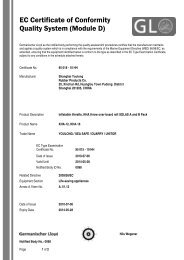
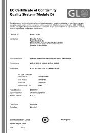
Airclean is CE-marked.<br />
E.1.2 Lubrication<br />
The air motor requires lubricated air. In order to ensure uninterrupted steady operation you must never<br />
let the fitted air lubricator run dry. The correct position of the adjustment screw is approx. 1/2-1 turn.<br />
E.1.3 Air operating pressure<br />
Do not exceed maximum safe air operating pressure specified in data sheet, enclosure 1.<br />
E.1.4 Frost protection<br />
If frost is expected, the waterside must be emptied to prevent damage by frost. This is simple. Disconnect<br />
the water supply and let the unit run some strokes until the pump, hose, spray gun and extension<br />
tube is empty. Or change over the air supply to the water intake and blow the waterside dry.<br />
E.1.5 Guarantee<br />
The guarantee is not valid for damages caused by erroneous usage or if the unit has been disassembled<br />
without written permission from the manufacturer.
E.2<br />
DESCRIPTION AND OPERATION<br />
4<br />
E.2.1 Pump unit<br />
The pump unit comprises a single acting pump powered by a double acting air motor. An air shuttle<br />
valve that changes the air direction when the piston reaches the end positions controls the air motor.<br />
E.2.2 Water inlet<br />
The connection is marked “Water”. Use a water supply hose with minimum diameter as specified in<br />
enclosure 2 “Dimensioning of water- and air inlet”. It is recommended to connect a low-pressure hose<br />
of minimum 3 meters length to the water inlet of the unit to prevent shock in the water system.<br />
The suction head capacity of the pump is reduced with increasing temperatures. Increased supply pressure<br />
may therefore be required when pumping hot water. The suction line must be free from leeks.<br />
Claw couplings are not suitable for suction lines with pressures below atmospheric pressure.<br />
E.2.3 Air inlet<br />
The air connection is marked “Air”. Use air supply hose with minimum diameter as specified in enclosure<br />
E.2 “Dimensioning of water- and air inlet”. Do not fit valves, fittings etc. with less diameter than<br />
specified in enclosure E.2. If regulation is required at the unit, it is recommended to fit a full-bore ball<br />
valve and use this for throttling the air supply. If you are going to use an air pressure regulator it must<br />
be plentiful dimensioned for the airflow.<br />
E.2.4 Chemical dosing<br />
A high-pressure injector fitted between the high-pressure pump outlet and the high-pressure hose may<br />
dose chemicals. You may need to turn down the water pressure by throttling the air motor to achieve<br />
that the injector will work properly. We recommend to disconnect the injector when not in use because<br />
it “steals” pressure.<br />
E.2.5 Cleaning procedures<br />
Hot water, if available, will always give the best result and reduces the need for chemicals. The following<br />
procedures are recommended to get the best result when working with detergents:<br />
- Apply the detergent with a wide-angle spray. Start at the bottom and move upwards. The spray<br />
distance should be approximately 40 cm.<br />
- Leave the detergent to work approx. 3 minutes, or according to the manufacturer’s instructions.<br />
However, do not let detergent dry on the surface.<br />
- Start cleaning from the bottom and move upward. This prevents water to run down and dilute<br />
detergent below. The spraying distance should be 10 – 30 cm.<br />
- When cleaning is completed, wash down from the top to prevent stains. Use water generously.
E.2.6 Accessories<br />
5<br />
The Airclean standard scope of supply is tailored to cater for ordinary cleaning tasks in an efficient and<br />
economic manner. Special demands are met by made suit accessories, which may be procured when<br />
needed. Such accessories include:<br />
- Chemical injector.<br />
- Turbo nozzles and other nozzle types.<br />
- Sand blasting set for cleaning and de-scaling rusty steel structures etc.<br />
- Nozzles for opening clogged tubes.<br />
- Foam set for soap, disinfectants etc.<br />
- Air filters, water filters, couplings for water and air.<br />
- Extension tubes and extra hoses.<br />
- Airclean wheel lance. Complete lance system for efficient washing of high walls, ceilings etc.<br />
- Hose drums.<br />
E.3<br />
MAINTENANCE<br />
E.3.1 Preventive maintenance<br />
Preventive maintenance is limited to filling of lubrication oil, visual inspection and cleaning. Particular<br />
attention should be paid to high-pressure leaks and high-pressure hose. High-pressure leaks should be<br />
repaired straight away as they may increase rapidly if left unattended. The method of repair depends on<br />
where the leaks occur:<br />
a.<br />
b.<br />
c.<br />
Pump Seal<br />
A leak pump piston seal will cause a flow of water out of the drain hole on the bottom<br />
side of the pump cylinder.<br />
Threads<br />
All threads are BSP standard. The sole exception is the spray nozzle, which is NPT. All<br />
threads are assembled with sealing liquid, and leaks will normally never occur. However,<br />
if leaks should occur the threads must be cleaned and reassembled using either a<br />
sealing liquid or thread tape.<br />
High-pressure hose couplings<br />
The high-pressure hose couplings have metal-to-metal seals. To stop a leak, tighten the<br />
nut until the leak stops. If this does not work, open the coupling and inspect the sealing<br />
surfaces.<br />
High pressure cleaning is the best method for cleaning the unit.<br />
If the plant air is contaminated, for instance by rust, an air filter should be fitted. A water filter should<br />
be fitted if the water contains abrasive particles.<br />
E.3.2 Pump Unit Dismantling<br />
The pump unit is assembled by means of lock rings and may be split at A or B (Pump unit drawing).<br />
For access to the pump piston seal undo the tie bolts.
6<br />
E.3.3 Change of pump piston seal<br />
a. Loosen the attaching bolts.<br />
b. Pull the cylinder of the piston.<br />
c. Check the cylinder for scratches to see if honing or a replacement is required.<br />
d. Remove the lock pin for the front part of the piston and screw it off. Fit o-ring, pump seal and<br />
front part of the piston.<br />
e. Fit new slide rings.<br />
f. Lubricate piston, seal and slide rings to ease reassemble and prevent damages at start up.<br />
Reassemble sequence is opposite to dismantling, but note the following:<br />
g. Tighten the attaching-bolts two and two opposite at a time. Sealing liquid should be applied to<br />
the bolts.<br />
E.3.4 Pump valves<br />
The valve seats are fixed and are not removable. Proceed as follows to inspect/renew balls or springs:<br />
a. Undo attaching bolts and pull free the pump head to gain access to the inlet valve. The outlet<br />
reducer is fitted with sealing liquid.<br />
b. Clean and inspect parts. Remove loose scale etc. Replace worn parts.<br />
c. Clean threads.<br />
d. Fit parts according to drawing.<br />
e. Use sealing fluid on outlet reducer threads when assembling. Tighten opposite bolts to avoid<br />
skewing.<br />
E.3.5<br />
a.<br />
b.<br />
c.<br />
E.3.6<br />
a.<br />
b.<br />
c.<br />
d.<br />
Valve shuttle<br />
Unscrew threads end cover, remove dampening ring and pull out the valve shuttle.<br />
Dismantle, clean, inspect and replace parts as required.<br />
Re-assembly is done in reversed order. Screw in and end cover till it bottoms.<br />
Valve rod sealing<br />
Split pump unit by pulling lock ring B (See drawing)N5.<br />
Dismantle, clean, inspect and replace worn parts as required.<br />
Lubricate all o-rings prior to re-assembly.<br />
Re-assembly is done in reversed order.
E.3.7<br />
Fault diagnosis<br />
7<br />
Symptom<br />
Possible Cause and Solution<br />
1. Low delivery/pressure<br />
a) Restricted air supply.<br />
See E.2.3 “Air inlet”.<br />
Clean filters in the air supply.<br />
Open closed valves.<br />
b) Inadequate air supply capacity.<br />
Check compressor capacity.<br />
(See data sheet).<br />
Wrong nozzle bore. Change nozzle.<br />
Worn out nozzle. Change nozzle.<br />
2. Uneven operation<br />
a) Inadequate lubrication.<br />
b) Insufficient air supply<br />
3. Pump failure to start<br />
a) Pressure gauge on unit shows there is<br />
pressure: Clogged nozzle. Disconnect air<br />
supply and check for ice plug.<br />
b) Pressure gauge on unit shows no pressure:<br />
Closed air supply.<br />
Clogged air supply.<br />
No pressure in the air system.<br />
4. Pump runs without delivery or low deliv- a) Closed water supply.<br />
ery<br />
Check any valves and filters in the supply.<br />
b) To large suction head.<br />
c) Undersized valves/fittings in the supply.<br />
d) Blocked/restricted air supply.<br />
e) Leaking pump piston seal.<br />
5. Water/air leakages<br />
a) Defect pump piston seal or other seals<br />
6. Pump over-speeds with no or low delivery a) Lacking or no water supply.<br />
Check valves and filters.<br />
b) To high suction head.<br />
c) Restrictions in water supply.<br />
d) Leaking pump piston seal.<br />
7. Pump runs after trigger is released a) Pump inlet valve is damaged or blocked<br />
in open position.<br />
b) Leaking pump piston seal.<br />
8. Pulsating spray<br />
a) Leaking suction line.<br />
b) Only 1 pump is working<br />
9. Air motor stops and blows air<br />
a) Damage to o-ring seal(s) on air motor.<br />
Seals must be changed.
E.4<br />
ENCLOSURES<br />
8<br />
E1 Data sheet<br />
Airclean 32<br />
Pressure ratio 32 : 1<br />
No of cylinders<br />
Air motor cylinder diameter<br />
Pump cylinder diameter<br />
Stroke<br />
Capacity<br />
Air consumption (free air, 1 bar)<br />
Recommended air pressure<br />
Pump pressure<br />
Maximum inlet water pressure<br />
Suction head up to<br />
2 pcs<br />
125 mm<br />
22 mm<br />
75 mm<br />
0-24 l/min<br />
0-7.5 m3/min(125 l/s)<br />
5-11 bar<br />
0-350 bar<br />
25 bar<br />
4 m<br />
Maximum inlet water temperature 150 °C<br />
Water inlet nozzle<br />
Air inlet nozzle<br />
High pressure outlet<br />
Length overall<br />
Width overall<br />
Height overall (pump cart)<br />
High pressure hose<br />
Weight complete incl. hose, gun and lance<br />
Extension tube lenght<br />
3/4’’ BSP female<br />
3/4’’ BSP male<br />
3/8’’ BSP male<br />
720 mm<br />
520 mm<br />
980 (540) mm<br />
3/8’’x10 m<br />
55 kg<br />
700 mm<br />
MATERIALS<br />
Pump head<br />
Nickel and chrome plated st<br />
Pump valve seats Stainless steel AISI 316<br />
Pump valve springs Stainless steel AISI 301<br />
Pump piston seal<br />
PTFE/Carbon<br />
Piston rod Stainless steel AISI 303<br />
Valve ball<br />
Stainless steel AISI 420B<br />
Pump cylinder<br />
JM3 seawater resist. bronze<br />
Air cylinder<br />
Nickel and chrome plated st<br />
Valve rod Stainless steel AISI 303<br />
Frame<br />
Nickel and chrome plated st<br />
Tube parts<br />
Galvanized steel<br />
Cover<br />
Vacuum formed ABS<br />
Bolts<br />
Hot galvanized steel<br />
Spray gun<br />
Bronze/plastic<br />
Extension tube<br />
Nickel plated steel<br />
High pressure nozzle Stainless steel AISI 316<br />
The unit will be delivered complete with<br />
10m high pressure hose with spray gun,<br />
extension tube, spray nozzle, press. gauge,<br />
air lubricator and exhaust air muffler.<br />
Subject to be improved without notice
E2 Dimensioning of water- and air supply<br />
9<br />
RECOMMENDATIONS Airclean 32<br />
HOSE DIMENSIONS<br />
Water supply<br />
Use minimum 3/4’’ hose. If the supply pressure is low or the hose is long, a 1’’ hose is recommended.<br />
Air supply<br />
Use minimum 1’’ hose.<br />
Do not fit valves or fittings with less inner diameter than 19 mm.
E3 Part list<br />
AIRCLEAN 32<br />
PART NO U1200 PUMP UNIT<br />
10<br />
Part No Description Pos no Qty.<br />
P1002 Pump head 1 1<br />
P1037 Hex nut 2 1<br />
P1003 Stud screw 3 1<br />
P1204 Piston rod 4 1<br />
P1157 Glide ring 5 1<br />
P1106 Air piston 6 1<br />
P1007 Valve ball 7 2<br />
P1008 Hex screw 8 4<br />
P1019 Reduser 9 1<br />
P1010 Spring 10 1<br />
P1239 Pump cylinder 11 1<br />
P1012 Cylinder cover 12 1<br />
P1005 Spring 13 1<br />
P1249 Pump piston 14 1<br />
P1255 Glide ring 15 2<br />
P1119 Ring 16 2<br />
P1035 End cap 17 1<br />
P1256 Pump packing 18 1<br />
P1257 O-ring 19 1<br />
P1045 O-ring 20 1<br />
P1024 O-ring 21 5<br />
P1123 O-ring 22 2<br />
P1026 O-ring 23 6<br />
P1025 O-ring 24 6<br />
P1159 O-ring 25 6<br />
P1158 Liner 26 1<br />
P1166 Sleeve 27 1<br />
P1027 Air cylinder 28 1<br />
P1134 Valve shuttle 29 1<br />
P1267 Valve housing 30 1<br />
P1016 Snap ring 31 2<br />
P1164 Sleeve 32 1<br />
P1236 Valve rod 34 1<br />
P1168 O-ring 35 1<br />
P1080 Elbow 36 3<br />
P1081 Hose nipple 37 2<br />
P1082 Return line 38 1<br />
P1083 Hose clip 39 2<br />
P1084 Adapter 40 1
E4 Pump drawing<br />
11