technical report - the Marine Advanced Technology Education (MATE)
technical report - the Marine Advanced Technology Education (MATE)
technical report - the Marine Advanced Technology Education (MATE)

Create successful ePaper yourself
Turn your PDF publications into a flip-book with our unique Google optimized e-Paper software.
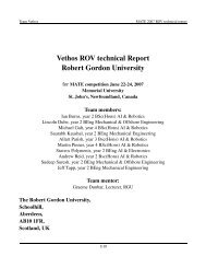
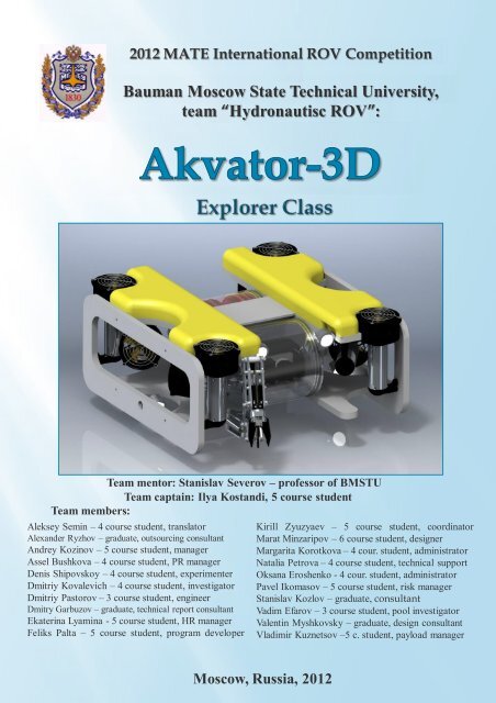
2012 <strong>MATE</strong> International ROV Competition<br />
Bauman Moscow State Technical University,<br />
team “Hydronautisc ROV”:<br />
Team mentor: Stanislav Severov – professor of BMSTU<br />
Team captain: Ilya Kostandi, 5 course student<br />
Team members:<br />
Aleksey Semin – 4 course student, translator<br />
Alexander Ryzhov – graduate, outsourcing consultant<br />
Andrey Kozinov – 5 course student, manager<br />
Assel Bushkova – 4 course student, PR manager<br />
Denis Shipovskoy – 4 course student, experimenter<br />
Dmitriy Kovalevich – 4 course student, investigator<br />
Dmitriy Pastorov – 3 course student, engineer<br />
Dmitry Garbuzov – graduate, <strong>technical</strong> <strong>report</strong> consultant<br />
Ekaterina Lyamina - 5 course student, HR manager<br />
Feliks Palta – 5 course student, program developer<br />
Kirill Zyuzyaev – 5 course student, coordinator<br />
Marat Minzaripov – 6 course student, designer<br />
Margarita Korotkova – 4 cour. student, administrator<br />
Natalia Petrova – 4 course student, <strong>technical</strong> support<br />
Oksana Eroshenko - 4 cour. student, administrator<br />
Pavel Ikomasov – 5 course student, risk manager<br />
Stanislav Kozlov – graduate, consultant<br />
Vadim Efarov – 3 course student, pool investigator<br />
Valentin Myshkovsky – graduate, design consultant<br />
Vladimir Kuznetsov –5 c. student, payload manager<br />
Moscow, Russia, 2012
It’s <strong>the</strong> third time <strong>the</strong> BMSTU team is<br />
participating in <strong>the</strong> competitions <strong>MATE</strong>C.<br />
The backbone of <strong>the</strong> team is students of<br />
Underwater robots Department of BMSTU.<br />
This time <strong>the</strong> <strong>the</strong>me of <strong>the</strong> competition is<br />
associated with <strong>the</strong> pollution of water areas<br />
around <strong>the</strong> world.<br />
During <strong>the</strong> World War II about<br />
10.000 ships sank – this is about threequarters<br />
of all diesel ships sunk in <strong>the</strong><br />
history of mankind. Overall volume of oil<br />
in <strong>the</strong>se ships is 20 times greater than <strong>the</strong><br />
amount of oil spilled during Gulf of Mexico<br />
accident.<br />
One of <strong>the</strong> current competition<br />
missions poses a problem of pumping out<br />
<strong>the</strong> oil from <strong>the</strong> fuel tank of <strong>the</strong> sunken<br />
ship. We have developed a special device<br />
for solving this problem. ROV provides<br />
access to <strong>the</strong> tank using manipulator, <strong>the</strong>n<br />
attaches itself to <strong>the</strong> tank. After that<br />
operator activates a pumping oil<br />
mechanism.<br />
Sunken ships have undergone a<br />
severe corrosion since <strong>the</strong> wrecking and<br />
represent a great threat to <strong>the</strong> global<br />
environment. Destroyed ship hulls must be<br />
extracted from <strong>the</strong> seabed. At <strong>the</strong><br />
competition our team is required to locate<br />
metallic samples at <strong>the</strong> bottom of <strong>the</strong> pool.<br />
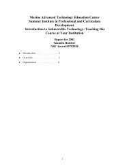
Akvator-3D (Fig. 1) is equipped with metal<br />
detector and can easily find <strong>the</strong>se objects.<br />
For mapping <strong>the</strong> bottom, <strong>the</strong> vehicle must<br />
accurately determine its orientation in<br />
space. Our ROV has a compass which<br />
indications are displayed on <strong>the</strong> operator's<br />
screen. To determine <strong>the</strong> dimensions of <strong>the</strong><br />
sunken ship hull Akvator-3D uses a tape<br />
measure with a special hook which attaches<br />
to <strong>the</strong> frame of wreck.<br />
Fig.1 3D Model of Akvator 3D<br />
2
Abstract.......................................................................................................................................... 2<br />
Table of contents: ......................................................................................................................... 3<br />
Budget/Expense sheet ................................................................................................................ 4<br />
Electrical schematic ...................................................................................................................... 5<br />
Design Rationale .......................................................................................................................... 8<br />
Frame .......................................................................................................................................... 8<br />
Buoyancy ................................................................................................................................... 8<br />
The pressure hull ...................................................................................................................... 8<br />
3D Vision System ...................................................................................................................... 9<br />
Propulsion system .................................................................................................................. 10<br />
Orientation sensor .................................................................................................................. 11<br />
Control complex ..................................................................................................................... 11<br />
Payload Description .................................................................................................................. 12<br />
Task #1: Survey <strong>the</strong> shipwreck site ..................................................................................... 12<br />
Metal detector ...................................................................................................................... 12<br />
Rangefinder ......................................................................................................................... 12<br />
Depth sensor ........................................................................................................................ 13<br />
Compass ............................................................................................................................... 14<br />
Task #2: Removing fuel oil from <strong>the</strong> shipwreck ................................................................ 14<br />
Manipulator ......................................................................................................................... 14<br />
Lift Bag ................................................................................................................................. 15<br />
Oil extractor ......................................................................................................................... 15<br />
Troubleshooting techniques ..................................................................................................... 16<br />
Challenges ................................................................................................................................... 17<br />
Future Improvement ................................................................................................................. 17<br />
Lessons Learned ......................................................................................................................... 18<br />
Reflections ................................................................................................................................... 18<br />
Teamwork ................................................................................................................................... 18<br />
References ................................................................................................................................... 19<br />
Acknowledgements ................................................................................................................... 20<br />
3
Budget/Expense sheet<br />
Period: since 1.09.2012 till 20.06.2012<br />
University: Bauman Moscow State Technical University<br />
Mentor: Stanislav Severov<br />
Funds: BMSTU; TETIS; RASIO; RISM; SCOLIPE; Students<br />
№ Item Quantity<br />
Price per<br />
item, $<br />
Total<br />
amount, $<br />
1 Thrusters,based on MAXON 150 V 8 1016,1 8128,5<br />
2 Camera box 1 794,3 794,3<br />
3 Electronics housing 1 856,0 856,0<br />
4 Digital video cameras 2 420,7 841,3<br />
5 Rotatable camera box 1 769,7 769,7<br />
6 Self-made signal and power cable for neutral buoyancy 30 7,1 213,0<br />
7 Pressure sensor (strain sensor) 1 120,7 120,7<br />
8 Orientation sensor VectorNav VN-100 1 717,7 717,7<br />
9 Surface control system box 1 538,6 538,6<br />
10 3-axial manipulator(frame) 1 166,7 166,7<br />
11 Pneumatic cylinders for manipulator 8 28,2 225,3<br />
12 Manipulator control box 2 615,4 1230,8<br />
13 Manipulator’s servo drive 4 68,5 274,1<br />
14 Camera’s and equipment servos 5 25,4 127,2<br />
15 LED illuminators 20 W 4 28,4 113,6<br />
16 Hardware platform Arduino 4 85,7 342,7<br />
17 Electronics 1 287,4 287,4<br />
18 Manufacturing pc boards 4 154,3 617,3<br />
19 Secondary power supply unit 1 564,7 564,7<br />
20 Buoyancy * 2 128,3 256,7<br />
21 3D parts of equipment 1 1874,4 1874,4<br />
22 ROV’s frame(polypropylene) 1 204,3 204,3<br />
23 Car monitor 1 416,7 416,7<br />
24 120 Hz Display 1 789,7 789,7<br />
Total: 20471,3<br />
*donation<br />
4
The basic concepts of Akvator-3D “on<br />
board” circuit organization and pressure<br />
hull design are modular and<br />
interchangeability principles. Such solution<br />
allows us quick repair opportunities and<br />
gives us a chance for easy adding new board<br />
circuits in <strong>the</strong> pressure hull. Hence, future<br />
improvements and adding new tools<br />
wouldn’t be as complicated as <strong>the</strong>y were<br />
before.<br />
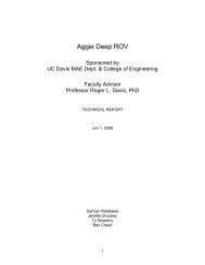
Power unit (Fig. 2) contains two DC-<br />
DC converters (48V to 12V and 48V to 5V),<br />
which supply all ROV units with electrical<br />
energy. Total power consumption is limited<br />
by 2kW. That is why 40A safety fuse is used.<br />
Propulsion system control circuit is<br />
based on 8 H-bridges formed by N-channel<br />
metal-oxide-semiconductor field effect<br />
transistors (MOSFET) IRFP4568. L6390 halfbridge<br />
gate drivers are used for controlling<br />
<strong>the</strong> H-bridge MOSFETs. STM Electronics<br />
recommends bootstrap circuitry to supply<br />
<strong>the</strong> high voltage section of <strong>the</strong> h-bridge.<br />
Using this circuitry has some disadvantages.<br />
The most important one for us is that<br />
bootstrap circuitry has limited duty-cycle<br />
(from 5% to 90%). We solved this problem<br />
by replacing <strong>the</strong> bootstrap circuitry and<br />
using TME1212 dc/dc converter instead.<br />
Propulsion control system circuit is<br />
driven by 16 PWM signals. Components of<br />
<strong>the</strong> circuit were selected in such a way that<br />
power dissipation on <strong>the</strong>m is low that<br />
means that <strong>the</strong> circuit doesn’t heat up and<br />
doesn’t influence stability of <strong>the</strong>rmo<br />
sensitive chips. Also mounting heat<br />
radiators and developing cooling system are<br />
not required. Thruster control electric<br />
circuit diagram is presented in Figure 3.<br />
Propulsion control system is<br />
represented by two boards - horizontal and<br />
vertical motion thruster’s controllers. These<br />
boards are schematically identical, which<br />
makes <strong>the</strong>m easier to produce and to replace<br />
failed ones “in <strong>the</strong> field”. There are also two<br />
backup MOSFET half-bridges on each board<br />
to operate ROV lighting system. Besides,<br />
<strong>the</strong>y allow us to complete a control system<br />
of <strong>the</strong> hydraulic manipulator with three<br />
degrees of freedom.<br />
Akvator-3D control systems are<br />
based on Atmel microcontroller units. All<br />
MCUs are connected via I 2 C bus.<br />
Communications block diagram is<br />
presented in Figure 4.<br />
The electronics housing contains 4<br />
boards at <strong>the</strong> moment: vertical and<br />
horizontal motion thrusters controllers,<br />
communication controller and pressure<br />
sensor processing board. DC-DC converters<br />
are also located on those boards.<br />
Fig. 2 Power supply circuit<br />
5
Fig. 3 Thruster control electric circuit diagram<br />
Fig. 4 Block diagram of communications<br />
6
ROV control system features depth and<br />
yaw stabilisation systems. They use<br />
unique depth sensor designed by<br />
members of our team and Vectornav<br />
VN-100 orientation sensor. Our<br />
stabilization system can provide 1 cm<br />
depth accuracy and 1 degree yaw<br />
accuracy. The stabilization algorithm is<br />
presented on Figure 5.<br />
Fig. 5 Flow chart of stabilization system<br />
software<br />
7
Frame<br />
The basis of all power and loadbearing<br />
structure of Aqvator-3D is a<br />
polypropylene frame. Thrusters, pressure<br />
hulls, buoyancy elements, weights and<br />
payload are all attached to <strong>the</strong> frame. This<br />
material was chosen because of its hardness,<br />
toughness and positive buoyancy. Plate<br />
frame material is better than PVC pipe.<br />
Tubular frame has a higher hydrodynamic<br />
resistance and added mass inertia than <strong>the</strong><br />
plate frame. In addition, plate frame<br />
stabilizes ROV’s motion in <strong>the</strong> longitudinal<br />
direction. Last year we used a frame of PVC<br />
pipe in <strong>the</strong> construction of ROV Akvator<br />
2010 and saw it firsthand. Processing of <strong>the</strong><br />
frame was performed according to <strong>the</strong><br />
students’ blueprints, using hydraulic<br />
cutting. It is worth mentioning that <strong>the</strong><br />
frame was made only after 3D modeling<br />
(Solid Works environment) of <strong>the</strong> entire<br />
vehicle was completed. While installing<br />
equipment on <strong>the</strong> frame, <strong>the</strong> team strictly<br />
adhered to 3D-drawings.<br />
Buoyancy<br />
In conjunction with <strong>the</strong> o<strong>the</strong>r<br />
components buoyancy lighter elements,<br />
made of polypropylene foams, are mounted<br />
on <strong>the</strong> frame. Elements balance <strong>the</strong> vehicle<br />
using <strong>the</strong> residual buoyancy. They were precalculated<br />
in Solid Works environment.<br />
Their geometry and location were chosen for<br />
<strong>the</strong> baseline condition of neutral buoyancy<br />
of entire ROV and <strong>the</strong> absence of hydrostatic<br />
moments of heel and trim. Fur<strong>the</strong>r on, we<br />
got <strong>the</strong> excess positive buoyancy of 20%,<br />
when <strong>the</strong> vehicle was in construction, up to<br />
5-10% in working condition. Adjusting was<br />
carried out using balancing weights. As a<br />
result, Akvator-3D should have small<br />
positive buoyancy at any time, which<br />
provides emergency ascent, if propulsion<br />
system is crashed.<br />
The pressure hull<br />
The ROV, including pressure hulls, is<br />
designed according to <strong>the</strong> block-module<br />
principle. Akvator-3D consists of several<br />
waterproof hulls for different purposes. The<br />
electronics hull and <strong>the</strong> camera hull are of<br />
particular importance. They are <strong>the</strong> two<br />
biggest and most crucial hulls of <strong>the</strong> vehicle.<br />
They are made of a 180 mm cylindrical pipe<br />
that is shut from both sides by aluminum<br />
lids with hermetical lead-ins. The electronics<br />
hull contains <strong>the</strong> whole electronic part of <strong>the</strong><br />
ROV’s control system. It includes a<br />
connection controller, an active propelling<br />
control board complex, special devices<br />
controllers and o<strong>the</strong>rs. Two Full HD video<br />
cameras are installed into <strong>the</strong> camera hull on<br />
a rotary mechanism. The fact that no bolts<br />
are used for <strong>the</strong> construction of <strong>the</strong> hulls is a<br />
distinctive feature. Radial rubber packing<br />
hoops that are located at <strong>the</strong> outer diameter<br />
of <strong>the</strong> hull covers provide hermetical<br />
adjoining of <strong>the</strong> covers to <strong>the</strong> plexiglass<br />
pipe.<br />
8
In order to disassemble those pressure hulls<br />
<strong>the</strong> hull should only be pulled out from <strong>the</strong><br />
special socket where <strong>the</strong> side covers are<br />
fixed by <strong>the</strong> elements of <strong>the</strong> frame. It is<br />
particularly useful during competitions<br />
when <strong>the</strong>re is a lack of time.<br />
There are several small pressure hulls<br />
in <strong>the</strong> structure of <strong>the</strong> ROV for <strong>the</strong> detached<br />
elements of <strong>the</strong> system that for some reason<br />
were taken out of <strong>the</strong> two main hulls. The<br />
orientation sensor unit is among <strong>the</strong>m. The<br />
hull is a monolith part of an extremely<br />
complex shape. Students are able to build it<br />
in a short time because of <strong>the</strong> complex<br />
integrative usage of <strong>the</strong> computer 3D<br />
modeling and manufacturing, with <strong>the</strong> use<br />
of <strong>the</strong> same 3D model on a 3D printer. Thus,<br />
<strong>the</strong> hermetical orientation sensor hull<br />
consists of a base, where <strong>the</strong> sensing unit is<br />
located, and a cover that presses it down.<br />
The hull is special as it almost does not<br />
diminish <strong>the</strong> pressure effect on <strong>the</strong> hull of<br />
<strong>the</strong> sensor itself, but on <strong>the</strong> contrary is<br />
supported by <strong>the</strong> sensor. The only function<br />
of this hull is to ensure leak tightness.<br />
People see <strong>the</strong> three dimensional<br />
world; it allows us to determine <strong>the</strong> distance<br />
to objects. However, this effect is not<br />
transmitted to <strong>the</strong> camera. Flat picture does<br />
not contain information of <strong>the</strong> mutual<br />
distance of <strong>the</strong> objects and it complicates <strong>the</strong><br />
work of <strong>the</strong> pilot.<br />
We equipped our vehicle with stereo<br />
vision system Full HD. This system (Fig. 6)<br />
consists of:<br />
1) 2 digital Full HD cameras on<br />
board;<br />
2) Surface module that combines<br />
images from <strong>the</strong> cameras and creates a<br />
frame-packing 3D HDMI;<br />
3D Vision System<br />
Nearly <strong>the</strong> same <strong>technical</strong> solution of <strong>the</strong><br />
usage of <strong>the</strong> reliability of <strong>the</strong> sealed elements<br />
is prominent in o<strong>the</strong>r hermetical containers,<br />
particularly in a laser range-finder operator<br />
box.<br />
Fur<strong>the</strong>rmore two hulls of <strong>the</strong> electric,<br />
mechanic and hydraulic transformation<br />
system are installed on <strong>the</strong> vehicle. The<br />
systems are a part of <strong>the</strong> manipulator<br />
control system. They are carefully inserted<br />
in <strong>the</strong> space between <strong>the</strong> camera hull and<br />
<strong>the</strong> electronics hull. The transformer hulls<br />
are complexly shaped and are also<br />
manufactured on a 3D printer.<br />
All pressure hulls are designed for 1,5<br />
MPa pressure that corresponds to 150 m<br />
depth. The calculations were performed in<br />
Solid Works package. The results meet <strong>the</strong><br />
requirements. Underwater experiments and<br />
pressure, stiffness and leak tightness tests<br />
were conducted at 6 m depth after <strong>the</strong><br />
assembling, which corresponds to <strong>the</strong> water<br />
levels of <strong>the</strong> competition pool. All pressure<br />
hulls were operating properly at this depth.<br />
3) Monitor, supporting NVIDIA 3D.<br />
Fig. 6 3D Vision System<br />
9
We can obtain three-dimensional<br />
image at small distances from <strong>the</strong> camera<br />
with this system. It is much easier to work<br />
with <strong>the</strong> manipulator and o<strong>the</strong>r devices and<br />
also it makes easier to operate ROV and<br />
navigate it in <strong>the</strong> space.<br />
Propulsion system<br />
By definition, ROV is an underwater<br />
movable object. The most difficult and<br />
responsible nodes of each ROV are<br />
thrusters. ROV performance, stabilization<br />
system characteristics, speed and propulsion<br />
of <strong>the</strong> robot depend on thrusters. Thus, <strong>the</strong>y<br />
are <strong>the</strong> most expensive parts of <strong>the</strong> vehicle.<br />
In addition, thrusters must meet <strong>the</strong><br />
requirements of <strong>MATE</strong>C and <strong>the</strong> aspects of<br />
<strong>the</strong> work in a fresh-water pool.<br />
After analyzing last year’s experience<br />
and a quota of 2000 W of electrical power,<br />
we decided to install four vertical and four<br />
horizontal thrusters according to <strong>the</strong> vector<br />
diagram. Based on <strong>the</strong> maximum of electric<br />
power for propulsion system we have<br />
developed specification for thrusters and<br />
completed it. The result of our semi-annual<br />
work is a propulsion system with <strong>the</strong> power<br />
of 150 W, based on collector motors<br />
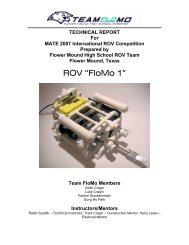
MAXON. These thrusters (Fig. 7), meet all<br />
<strong>the</strong> requirements of <strong>MATE</strong>C competitions<br />
and are suitable for competition missions.<br />
Sealing of <strong>the</strong> elongated shaft is<br />
carried out through a system of 2-reinforced<br />
cuffs (glands), which is structurally simple,<br />
and quite sufficient for <strong>the</strong> stated depths.<br />
Propulsion power in <strong>the</strong> mooring mode is 26<br />
N. Grating, which is installed on both sides<br />
of <strong>the</strong> thrusters, eliminate <strong>the</strong> possibility of<br />
foreign objects falling into <strong>the</strong> propeller and<br />
make <strong>the</strong> unit safe even for children.<br />
Fig. 7 Thruster<br />
10
Orientation sensor<br />
A well-known orientation sensor<br />
Vectornav VN-100 (Fig. 8) is used for <strong>the</strong><br />
positioning of <strong>the</strong> vehicle in space. In <strong>the</strong><br />
main mode (AHRS, attitude heading<br />
reference system) sensor provides three<br />
separate angle measurements, angular<br />
velocities and linear accelerations in all three<br />
axes. Measuring accuracy is provided by<br />
built-in Kalman filter. In addition, <strong>the</strong><br />
gyrostabilizer mode (IMU, Inertial<br />
measurement unit) allows us to receive data<br />
directly from <strong>the</strong> accelerometers,<br />
magnetometers and gyroscopes sensors that<br />
we partly use.<br />
VN-100 clock pulses set <strong>the</strong> frequency<br />
of <strong>the</strong> stabilization system loop. The sensor’s<br />
update rate is as high as 200 Hz, which<br />
allows us to create a high-speed control<br />
system, including both depth and direction<br />
stabilization. The smooth spatial motion and<br />
accessible control system provides <strong>the</strong><br />
ability to perform complex tasks of<br />
competition missions, which require high<br />
precision and maneuvering capabilities from<br />
ROV Akvator-3D.<br />
Fig. 8 Orientation sensor<br />
Control complex<br />
To be able to quickly start operations<br />
in various conditions we have developed a<br />
mobile control station for our underwater<br />
vehicle (Fig. 9). It includes:<br />
• impact-resistant container for <strong>the</strong><br />
equipment<br />
• 30-Inch widescreen display with<br />
support of 3D view technology<br />
• joysticks to control ROV (<strong>the</strong> same<br />
are used in aircraft simulators)<br />
• power units of 2 kW for <strong>the</strong> entire<br />
ROV<br />
• <strong>the</strong> small-sized placard to display<br />
real-time readings from sensors<br />
• converter to generate a stereo video<br />
sequence<br />
• mini-computer to communicate<br />
peripheral devices with ROV.<br />
Fig. 9 Control complex<br />
11
Task #1: Survey <strong>the</strong> shipwreck site<br />
To determine <strong>the</strong> type of sunken<br />
tanker‘s debris we decided to look into two<br />
devices: active sensor and flux-gate meter.<br />
The sensor (Fig. 10-a) allows quick locating<br />
of metal in <strong>the</strong> samples and saves a lot of<br />
time. However, <strong>the</strong> team faced difficulties,<br />
as sensor needed a shield and produced a<br />
lot of noise that interfered with <strong>the</strong> work of<br />
<strong>the</strong> device. The solution could be to carry<br />
out <strong>the</strong> sensor away from <strong>the</strong> vehicle at 40<br />
cm, but this would make <strong>the</strong> design of our<br />
ROV too complicated. So <strong>the</strong> team<br />
developed and produced a simple flux-gate<br />
Metal detector<br />
One of <strong>the</strong> competition’s missions is<br />
to measure <strong>the</strong> length of <strong>the</strong> sunken ship. In<br />
order to do this, our team looked into<br />
several distance measuring methods:<br />
acoustic, geometric, kinematic, laser, and<br />
mechanical. After a thorough research, we<br />
developed and tested two different devices:<br />
1)Laser rangefinder<br />
2)Roulette with a flexible metal tape<br />
(Fig. 11)<br />
Laser Rangefinder was sealed in<br />
polymeric container. Plate of silica glass was<br />
inserted into <strong>the</strong> lens. This device can make<br />
measurements up to 6 m, which satisfies <strong>the</strong><br />
requirements of <strong>the</strong> competitions mission in<br />
2012. Also we constructed a graph, with <strong>the</strong><br />
help of which a conversion factor for<br />
underwater measurements can be found.<br />
There is a particular issue in <strong>the</strong><br />
measuring speed of a laser rangefinder<br />
meter using a permanent magnet attached to<br />
a flexible tube (Fig. 10-b).<br />
Rangefinder<br />
Fig. 10 Metal detector a) – active, b) - passive<br />
underwater. If <strong>the</strong> distance is close to<br />
maximum (6 m), <strong>the</strong> delay is about 5<br />
seconds. This implies higher demands for<br />
stabilization and positioning system.<br />
As a result, roulette was chosen, mainly,<br />
because it can measure <strong>the</strong> distance faster.<br />
However, laser rangefinder can be used as<br />
an alternative tool for measuring <strong>the</strong> length<br />
of <strong>the</strong> sunken ship and various distances.<br />
a)<br />
b)<br />
a) b)<br />
Fig. 11 Range finders: a) – laser rangefinder,<br />
b)- roulette with a flexible metal tape<br />
12
Depth sensor<br />
Depth sensor is based on strain gauge<br />
pressure transducer (Fig. 12) Maximum<br />
allowable pressure is 15 PSI, which<br />
corresponds to <strong>the</strong> immersion depth of 10m.<br />
Electrical schematic diagram (Fig. 13) shows<br />
<strong>the</strong> scheme of <strong>the</strong> sensor power supply, as<br />
well as scaling and filtering of <strong>the</strong> output<br />
signal, developed by students.<br />
As you can see, 14-bit analog-digital<br />
converter is used in this scheme. The<br />
microcontroller Atmel recieves <strong>the</strong> data,<br />
where it undergoes additional software<br />
filtering. Accuracy of <strong>the</strong> depth<br />
measurement is 1 cm.<br />
The desirability and necessity of a<br />
functional depth sensor in<br />
<strong>the</strong> payload seems obvious. If necessary,<br />
we are prepared to explain our decision to<br />
install <strong>the</strong> depth sensor at <strong>the</strong> engineering<br />
evaluation.<br />
Fig. 12 strain gauge pressure transducer<br />
Fig. 13 Depth sensor electrical schematic diagram<br />
13
Compass<br />
For operator’s convenience magnetic<br />
compass is included in <strong>the</strong> vehicle’s<br />
payload. A different type of compass is<br />
combined with <strong>the</strong> orientation sensor. These<br />
decisions are made to ensure <strong>the</strong> reliability<br />
of determining <strong>the</strong> orientation of <strong>the</strong> wreck<br />
and location of objects on <strong>the</strong> site of <strong>the</strong><br />
shipwreck. In <strong>the</strong> event of unexpected<br />
failure and crash of both onboard sensors<br />
due to <strong>the</strong> influence of magnetic field of <strong>the</strong><br />
steel reinforcement of <strong>the</strong> pool’s building,<br />
<strong>the</strong> vehicle is equipped with portable<br />
professional compass. This device could be<br />
used on a prelaunch training. We tested <strong>the</strong><br />
device in <strong>the</strong> diving pool in Russian State<br />
University of Physical <strong>Education</strong> in<br />
Moscow.<br />
We are informed that EXPLORER<br />
class teams must define <strong>the</strong> orientation from<br />
<strong>the</strong> stern toward <strong>the</strong> bow of <strong>the</strong> ship. The<br />
BMSTU team will be able to use<br />
master compass or a designated north/so<br />
uth line to calibrate <strong>the</strong>ir own compass<br />
or sensors.<br />
Task #2: Removing fuel oil from <strong>the</strong> shipwreck<br />
Manipulator<br />
Most multifunctional element of<br />
construction of Akvator 3D is three<br />
dimension manipulator (Fig. 14).<br />
Manipulator is used for positioning a<br />
thickness sensor and labeled neutrons<br />
sensor.<br />
Manipulator could be used for<br />
transplantation coral models, moving mast,<br />
penetration to <strong>the</strong> fuel tank ports and o<strong>the</strong>r<br />
operations. Design of <strong>the</strong> manipulator is<br />
based on pneumatic cylinders witch<br />
commonly used in airplane models for<br />
nomination of <strong>the</strong> chassis. We applied<br />
aerospace technology to <strong>the</strong> underwater<br />
robotic design. Every wetted cylinder is set<br />
in motion by ano<strong>the</strong>r cylinder (we can call it<br />
main cylinder) which is located in <strong>the</strong> dry<br />
pressure hull of ROV. Main cylinder is<br />
connected with powerful servo mechanism.<br />
Manipulator was designed as a<br />
multifunctional device for various missions.<br />
It can interact with all attachments of <strong>the</strong><br />
ROV. Every new task require adaptation of<br />
executive body’s parts and microprocessors’<br />
programs.<br />
Fig. 14 Manipulator<br />
14
Lift Bag<br />
Hydrostatic uplift of <strong>the</strong> lift bag is<br />
created and regulated by <strong>the</strong> volume of <strong>the</strong><br />
fluid, which is forced by <strong>the</strong> airbag, placed<br />
in it. Lift bag design is presented in <strong>the</strong> form<br />
of a soft elastic airtight shell, placed in a<br />
sturdy loose-fitting grid. The elastic shell<br />
has a nipple with back valve for pumping<br />
and draining air. The underwater cargo<br />
should be attached by <strong>the</strong> grid. Pumping is<br />
performed with <strong>the</strong> use of airlift pump,<br />
which is used in <strong>the</strong> removal of oil from <strong>the</strong><br />
tanker. The proposed construction of <strong>the</strong> lift<br />
bag is technologically simple and easy to<br />
manufacture. It does not require <strong>the</strong> use of<br />
expensive materials and equipment. You<br />
can find more information about Lift bag in<br />
“Engineering Evaluation” part.<br />
It is known, that <strong>MATE</strong> Center, with<br />
<strong>the</strong> support from SUBSALVE USA<br />
(www.subsalve.com), will provide 25 pound<br />
lift bag to any EXPLORER class company.<br />
Alternatively companies are free to engineer<br />
or purchase its own lift bags. The weight of<br />
<strong>the</strong> EXPLORER class mast is between 50 and<br />
75 Newton (in water). BMSTU team will be<br />
able to use its own lift bag, as well as a lift<br />
bag provided by <strong>MATE</strong>C.<br />
Oil extractor<br />
For <strong>the</strong> removal <strong>the</strong> oil from <strong>the</strong><br />
tanker and its replacement with <strong>the</strong> salt<br />
water, we are using a special device (Fig.<br />
15). It consists of two fairly solid, but<br />
flexible polymer extractor tubes directed<br />
vertically downward. It also has conical<br />
hopper-catchers and inflatable torus elastic<br />
elements fitting <strong>the</strong> free ends of <strong>the</strong> tubes.<br />
At first, hopper-catchers are used.<br />
They make it easy to align <strong>the</strong> extractor tube<br />
in <strong>the</strong> holes. Fur<strong>the</strong>r, a solid plastic tip tube<br />
acts as a drill, penetrating through <strong>the</strong><br />
plugging layer of petroleum jelly. When <strong>the</strong><br />
pilot decides that <strong>the</strong> drilling is completed,<br />
and <strong>the</strong> tubes are immersed in <strong>the</strong> hole<br />
deep enough, rubber bags, which are<br />
slightly above <strong>the</strong> tip, are filled with <strong>the</strong> air.<br />
All above mentioned elements create an<br />
interconnected system, which consists of a<br />
tank vessel, inlet and outlet pipes going<br />
along <strong>the</strong> ROV’s cable, and <strong>the</strong> tank on <strong>the</strong><br />
surface. The surface tank has a movable<br />
partition, and is initially filled with <strong>the</strong> salt<br />
water. When <strong>the</strong> partition is set in motion,<br />
<strong>the</strong> salt water begins to fill <strong>the</strong> tube leading<br />
into <strong>the</strong> outflow port. At <strong>the</strong> same time, low<br />
pressure zone is formed in ano<strong>the</strong>r tank<br />
cavity, thus starting <strong>the</strong> pumping of <strong>the</strong> oil.<br />
Rubber bags’ inflating mechanism is also<br />
located on <strong>the</strong> surface and consists of a<br />
syringe with air.<br />
Fig. 15 Oil extractor<br />
15
During <strong>the</strong> testing process our team<br />
faced with <strong>the</strong> problem: while ROV was in<br />
<strong>the</strong> water - we often lost <strong>the</strong> signal, so that it<br />
became impossible to use microcontroller<br />
and take data from <strong>the</strong> sensors.<br />
We realized that this was happening<br />
because <strong>the</strong> connection between test<br />
connector and <strong>the</strong> “broaching cable” (which<br />
was wrapped in scotch tape) was not sealed<br />
properly. When <strong>the</strong> water flowed into <strong>the</strong><br />
wire, we lost <strong>the</strong> communication channel.<br />
At first it was proposed to buy a<br />
special sealed connectors, but due to <strong>the</strong>ir<br />
high cost, dimensions, and complexity of <strong>the</strong><br />
acquisition, <strong>the</strong> idea was rejected.<br />
After that we tried ano<strong>the</strong>r way to<br />
solve <strong>the</strong> problem. Our connecting cables<br />
were covered with <strong>the</strong> special adhesive tape.<br />
But this only reduced <strong>the</strong> number of faults,<br />
and besides this worked only when <strong>the</strong><br />
vehicle was underwater for brief periods of<br />
time. When diving was long, <strong>the</strong> problem<br />
surfaced again.<br />
With each dive, <strong>the</strong> probability to see<br />
stable readings decreased. First, <strong>the</strong>re were<br />
interruptions in <strong>the</strong> reception of sensor data<br />
management system. Then <strong>the</strong> data was<br />
available only when <strong>the</strong> thrusters were<br />
turned off, and soon it became impossible to<br />
get any valuable information.<br />
We decided that <strong>the</strong> problem was a<br />
bad soldering of wires, or <strong>the</strong>y were<br />
damaged. After a brief inspection of <strong>the</strong><br />
cable, it became clear that <strong>the</strong> veins were<br />
oxidized and blackened along <strong>the</strong> entire<br />
length, and leaving <strong>the</strong> wire in such<br />
condition was not an option. Therefore, a<br />
faulty cable was lowered into a specially<br />
made container with acid for soldering and<br />
remained <strong>the</strong>re until complete dissolution of<br />
<strong>the</strong> oxide film.<br />
During this time, <strong>the</strong> team found a<br />
workaround. We made "quick connector“<br />
(Fig. 16), which allowed only a single flash of<br />
<strong>the</strong> microcontroller (<strong>the</strong> main cable allowed<br />
to reprogram everything, because it<br />
contained several USB connectors.) It could<br />
be used only on <strong>the</strong> shore, but this provided<br />
an opportunity to visually evaluate <strong>the</strong><br />
efficiency of system.<br />
We had to restore <strong>the</strong> main cable, and<br />
<strong>the</strong>refore, after drying, <strong>the</strong> test connector<br />
was completely revised and redesigned. This<br />
time we used a slightly different design for<br />
better sealing, thus decreasing <strong>the</strong><br />
probability of water intrusion. The overall<br />
length of <strong>the</strong> wire was increased, which gave<br />
<strong>the</strong> team <strong>the</strong> possibility to distance power<br />
supply, electronics and laptop from <strong>the</strong> side<br />
of <strong>the</strong> pool.<br />
Fig. 16 "Quick Connector" and <strong>the</strong> final version of <strong>the</strong> basic socket.<br />
16
This year <strong>the</strong>re have been many<br />
<strong>technical</strong> problems. One of <strong>the</strong> competition<br />
tasks was <strong>the</strong> identification of metallic and<br />
nonmetallic debris on <strong>the</strong> site of <strong>the</strong><br />
shipwreck. We’ve boldly imagined<br />
ourselves as entrepreneurs of a virtual<br />
trading company UWIS-Underwater<br />
innovation systems. For metal detection<br />
tasks, we decided to develop a portable<br />
metal detector (Minelab type). We generally<br />
designed a retractable system, thought out<br />
its sealing, began to study <strong>the</strong> processing of<br />
signals, but <strong>the</strong>n encountered a strong<br />
induction of <strong>the</strong> interference from <strong>the</strong><br />
vehicle to metal detector and vice versa. We<br />
also underestimate <strong>the</strong> problem of limited<br />
space for <strong>the</strong> installation such voluminous<br />
device as metal detector.<br />
We had to put in place a simpler<br />
fluxgate device. Its capacity is sufficient for<br />
performing competitive tasks and to<br />
determine <strong>the</strong> nature of debris.<br />
The non-<strong>technical</strong> challenge that<br />
arose before <strong>the</strong> team was an effective<br />
communication with foreign colleagues.<br />
Last year we lost some points in <strong>the</strong><br />
competition because of <strong>the</strong> lack of expertise<br />
in translating <strong>technical</strong> documents. The<br />
mentor of <strong>the</strong> team, Stanislav Severov,<br />
identified five students, who took English<br />
courses to improve <strong>the</strong>ir knowledge of<br />
<strong>technical</strong> English. The BMSTU team also<br />
used <strong>the</strong> “Underwater Robotics: Science,<br />
Design & Fabrication” book, written by Dr .<br />
Steven W. Moore, Harry Bohm, and Vickie<br />
Jensen.” This book was indispensable in<br />
getting acquainted with <strong>the</strong> correct<br />
terminology in <strong>the</strong> field of underwater<br />
robotics. We are thankful to its authors.<br />
Our team reviewed a number of<br />
decisions taken in <strong>the</strong> design of <strong>the</strong> ROV’s<br />
devices this year, and made appropriate<br />
conclusions.<br />
We realized that electronics case<br />
should be placed vertically thus leaving<br />
free space for special equipment. In our<br />
present ROV, electronics case is positioned<br />
horizontally. It takes a lot of space on <strong>the</strong><br />
bottom of <strong>the</strong> frame and creates difficulties<br />
for <strong>the</strong> placement of devices.<br />
In <strong>the</strong> future we plan to make a<br />
symmetrical design, i.e. cameras, lights<br />
and devices will be located on both front<br />
and rear of ROV. The cameras will be<br />
placed in separate sealed cases, as it is<br />
done on <strong>the</strong> industrial ROVs.<br />
We also plan to remove <strong>the</strong> servo<br />
machines, used in manipulator system,<br />
and build a complete hydraulic system.<br />
17
Creating our own electronic circuit<br />
boards has given us a useful experience this<br />
year, but <strong>the</strong> most importantly we have<br />
managed to design original thrusters.<br />
Our programmers have studied and<br />
successfully applied new communication<br />
interfaces, such as I2C, SPI, RS485. They are<br />
used to establish a connection between <strong>the</strong><br />
vehicle and peripheral devices.<br />
We have developed control and<br />
stabilization system, which allows <strong>the</strong><br />
vehicle to keep a certain depth and angle of<br />
<strong>the</strong> course, as well as to compensate for<br />
external disturbances. Now <strong>the</strong> ROV has<br />
become much easier to operate.<br />
Participation in <strong>the</strong> <strong>MATE</strong><br />
International ROV Competition-2012 is a<br />
great opportunity for all BMSTU team<br />
members: both experienced and new. We<br />
are grateful to <strong>MATE</strong>C for <strong>the</strong> chance to<br />
get experience in <strong>the</strong> development of a<br />
real underwater vehicle, and extend <strong>the</strong><br />
boundaries of our competence. This is<br />
practical application of all knowledge that<br />
we receive during studies. It is marvelous<br />
that <strong>MATE</strong> competition provide an<br />
opportunity to test ourselves in different<br />
areas of engineering: electronics,<br />
programming, design, modeling, and<br />
project management. Many of <strong>the</strong> active<br />
project’s participants experienced an<br />
increase in academic performance.<br />
This year's BMSTU team includes<br />
mostly new members. All mistakes of <strong>the</strong><br />
previous teams were taken into account,<br />
and after having gone through this “school<br />
of trial and error”, we’ve decided to<br />
radically change attitude towards <strong>the</strong> team<br />
work in <strong>the</strong> project.<br />
Project "Akvator-3D" involves a lot<br />
of tasks in different directions of <strong>the</strong> project<br />
activity: organization, planning, design,<br />
supply, manufacturing, research, testing,<br />
etc. To manage such a large number of<br />
different tasks and operations a clear<br />
division of labor and responsibilities is<br />
needed. Gantt chart was used to schedule<br />
tasks by priority and deadline. We put all<br />
<strong>the</strong> work associated with <strong>the</strong><br />
implementation of <strong>the</strong> project in <strong>the</strong> chart<br />
and assigned responsibilities.<br />
Stanislav Severov, <strong>the</strong> team mentor,<br />
provided educational support to <strong>the</strong> team.<br />
Pavel Ikomasov, <strong>the</strong> risk manager,<br />
designed software for stabilization <strong>the</strong><br />
depth and route systems and wrote<br />
“Troubleshooting Techniques” part of<br />
<strong>technical</strong> <strong>report</strong>.<br />
Vadim Efarov, <strong>the</strong> pool investigator<br />
and engineer, and Dmitriy Pastorov,<br />
engineer, designed and created a control<br />
complex of Akvator-3D and wrote<br />
instructional documentation for it.<br />
Ekaterina Lyamina, <strong>the</strong> electronics<br />
engineer and HR manager, designed and<br />
created PCB of engine control driver,<br />
prepared documentation on vehicle’s<br />
electronics for <strong>technical</strong> <strong>report</strong>, and<br />
organized regular team meetings.<br />
18
Felix Palta, <strong>the</strong> program developer<br />
and electronics engineer, designed and<br />
implemented an onboard intercontroller<br />
communication using different interfaces;<br />
he also created a functional and electrical<br />
circuit’s link.<br />
Vladimir Kuznetsov, <strong>the</strong> payload<br />
manager, developed onshore software and<br />
communication link with <strong>the</strong> shore<br />
systems, and described <strong>the</strong> work of <strong>the</strong><br />
hydrostatic pressure sensor for <strong>the</strong><br />
<strong>technical</strong> <strong>report</strong>.<br />
Ilya Kostandi, <strong>the</strong> team captain and<br />
<strong>the</strong> main engineer of <strong>the</strong> vehicle,<br />
participaed in <strong>the</strong> development of <strong>the</strong><br />
multiple ROV systems and edited <strong>the</strong><br />
“Design Rationale” part.<br />
Dmitriy Kovalevich, <strong>the</strong><br />
investigator, and Denis Shipovskoy,<br />
experimenter developed a laser<br />
rangefinder for <strong>the</strong> ROV and a<br />
documentation for it.<br />
Natalia Petrova, <strong>the</strong> engineer and<br />
member of <strong>technical</strong> consultant, designed<br />
<strong>the</strong> stand for propulsion system<br />
measurements. She was in charge of<br />
creating test bottom equipment (20 units).<br />
Assel Bushkova, <strong>the</strong> PR manager,<br />
wrote and posted a series of press releases<br />
about team’s participation in <strong>MATE</strong>C<br />
competitions-2012 in Orlando.<br />
Valentin Myshkovskiy, <strong>the</strong> design<br />
consultant, provided consultations for<br />
programming on-board analog devices of<br />
ROV’s payload.<br />
Alexander Ryzhov, <strong>the</strong> outsourcing<br />
consultant, provided consultations <strong>the</strong><br />
development of <strong>the</strong> tools and devices of <strong>the</strong><br />
manipulation complex.<br />
Stanislav Kozlov, <strong>the</strong> consultant,<br />
organized <strong>the</strong> team work and took part in<br />
creating of <strong>the</strong> core product of <strong>the</strong> project-<br />
ROV «Akvator 3D».<br />
Dmitriy Garbuzov, <strong>the</strong> <strong>technical</strong><br />
<strong>report</strong> consultant, participated in <strong>the</strong><br />
testing of <strong>the</strong> analog devices of <strong>the</strong><br />
prototype vehicles.<br />
Marat Minzaripov, <strong>the</strong> designer,<br />
created <strong>the</strong> outer design of <strong>the</strong> vehicle and<br />
created <strong>the</strong> Poster for <strong>the</strong> <strong>MATE</strong><br />
competition.<br />
Alexey Syomin, <strong>the</strong> translator, took<br />
part in translating entire documentation<br />
part.<br />
Andrey Kozinov, <strong>the</strong> manager,<br />
collected, analyzed, and _ edited<br />
information for <strong>the</strong> Poster.<br />
Kirill Zyuzyaev, <strong>the</strong> coordinator,<br />
was responsible for collecting and editing<br />
materials for <strong>the</strong> Technical Report.<br />
Oksana Eroshenko, <strong>the</strong><br />
administrator, was responsible PR support<br />
and organizing team’s trips.<br />
Margarita Korotkova, <strong>the</strong><br />
administrator, was responsible for<br />
collecting and presenting team’s <strong>report</strong>s.<br />
http://www.marinetech.org/<br />
http://www.chipdip.ru/<br />
http://platan.ru/<br />
http://www.planet.com.tw/<br />
http://www.google.com<br />
http://en.wikipedia.org<br />
http://www.sparkfun.com<br />
http://www.solidworks.com<br />
http://www.minelab.com<br />
19
Acknowledgements<br />
MARINE ADVANCED TECHNOLOGY EDUCATION CENTER<br />
We have special acknowledgements to <strong>MATE</strong> Center for an<br />
opportunity to participate in <strong>the</strong>se competitions. Due to your support<br />
we have <strong>the</strong> opportunity to actively study new world’s problems and<br />
look for innovative ways of solving <strong>the</strong>m. It allows us to expand our<br />
knowledge about <strong>the</strong> practical application of ROV in <strong>the</strong> different fields<br />
of science.<br />
Special thanks for support and help:<br />
Bauman Moscow State Technical University<br />
The SM11 department «Underwater vehicles» BMSTU<br />
MINELAB. World's Best Metal Detection Technologies<br />
Russian Academy of Sciences Experimental Design Bureau of<br />
Oceanological Engineering<br />
Russian State University of Physical <strong>Education</strong>, Sport, Youth and<br />
Tourism (SCOLIPE)<br />
Russian Academy of Science. P. P. Shirshov Institute of Oceanology<br />
20