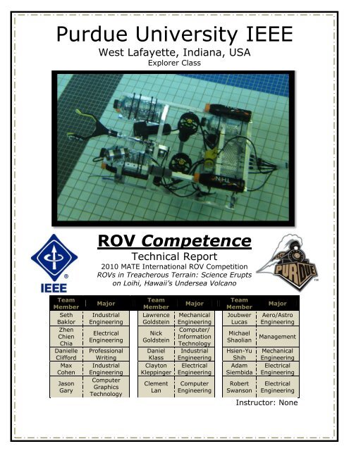
Technical Report - the Marine Advanced Technology Education ...
Technical Report - the Marine Advanced Technology Education ...
Technical Report - the Marine Advanced Technology Education ...
Create successful ePaper yourself
Turn your PDF publications into a flip-book with our unique Google optimized e-Paper software.
1. History: The Loihi SeamountThis year's MATE competition was inspired by <strong>the</strong> Loihi seamount and <strong>the</strong> expeditionsthat have explored it. As students and competitors, it is important to study <strong>the</strong>seamount itself and <strong>the</strong> processes behind it as well as <strong>the</strong> purpose of <strong>the</strong> expeditions to<strong>the</strong> seamount. This information greatly affects <strong>the</strong> design process and helps to inspirenew ideas in <strong>the</strong> minds of <strong>the</strong> team members. The previous expeditions serve as astarting point, but it is <strong>the</strong> goal of <strong>the</strong> competition and its competitors to find new andinnovative ways in which to conquer <strong>the</strong> challenges <strong>the</strong> seamount presents.In July of 1996, a series of seismic events began which formed <strong>the</strong> Loihi seamount.The entire set of events occurred between mid-July and early August consisting of fourthousand small earthquakes. These earthquakes were caused by hot magma rising to<strong>the</strong> surface underneath <strong>the</strong> sea floor. Research indicates that some of <strong>the</strong> magma maycome from <strong>the</strong> main volcano, Muana Loa, on <strong>the</strong> islandof Hawaii. The seamount is one of <strong>the</strong> youngest in <strong>the</strong>Hawaiian islands and is still active today.There were many research explorations launched toexplore <strong>the</strong> Loihi seamount. The earliest explorationswere conducted by Pisces V and were concernedmainly with collecting rock samples to be analyzed byseveral different methods in order to determine <strong>the</strong>chemical makeup of <strong>the</strong> seamount. The latestexplorations have been performed by HUGO, whichmonitors <strong>the</strong> seamount for recent activity. HUGO alsorecords sounds from around <strong>the</strong> seamount, increasing<strong>the</strong> types of data scientists can analyze.This year's mission incorporates HUGO andFigure 1.2 - Pisces V being deployed at a site.(courtesy of NOAA)Figure 1.1 - HUGO at <strong>the</strong> Loihi seamount.(courtesy of Hawaii Center of Volcanology)encompasses its tasks as well as some of <strong>the</strong> tasks<strong>the</strong> Pisces V manned submersible performed. Oneof this year's mission tasks is to determinelocations of seismic activity and move HUGO. Thisessentially re-deploys HUGO to a more active spotin order to obtain better data as <strong>the</strong> youngseamount develops. Collecting various samples ofcrustaceans and agar are reminiscent of <strong>the</strong> PiscesV explorations, giving us a better idea of <strong>the</strong> lifeand environment around <strong>the</strong> seamount. It is <strong>the</strong>goal of this competition and ROV Competence toperform <strong>the</strong>se tasks and more.See Section 8: References/Works Cited for researched sources2
3.4 ThrustersROV Competence uses six Seabotix BTD-15024Vdc thrusters. These thrusters were chosenbecause <strong>the</strong>y were <strong>the</strong> best available mix ofperformance, weight, size, and affordability. Theyeach produce 28.4N of thrust with a length of just17cm. Four thrusters are placed at a 25 degree angleoffset (see figure 3.9) for surge, yaw, and sway. Twothrusters are placed next to each o<strong>the</strong>r near <strong>the</strong>center of <strong>the</strong> vehicle for a balanced ascent. Thepositioning of <strong>the</strong> two thrusters favor roll over pitchbecause pitch control is not necessary due to <strong>the</strong>design of <strong>the</strong> manipulator system.The original design used six brushed DC motors incustom enclosures. These units, inspired by <strong>the</strong>thrusters used on <strong>the</strong> 2009 Long Beach CommunityCollege ROV, were designed to provide optimalperformance for this year’s challenges. The designfocused around a surplus DC motor press fit in athin wall aluminum tube. The motor is run at 48V,providing 120W with only 2.5A. The low ampdraw was favored due to <strong>the</strong> requirement that four motors must activateFigure 3.9 - Layout of thrusters in ROVCompetence as seen from abovewhenever <strong>the</strong> ROV is surging, swaying, oryawing. The enclosures were waterproofedwith duel o-ring seals between <strong>the</strong> aluminumtube and aluminum end caps. The front endcap contains a spring-reinforced PTFE shaftseal. Manufacturing proved to be morechallenging than originally expected. Despitethis, one prototype was completed, and dueto its high power output has instead beenchosen to power <strong>the</strong> rotation of <strong>the</strong>manipulator at reduced voltage.Figure 3.10 - Custom thruster enclosureoriginally intended to be used for all thrusters,now being used for manipulator rotation7
3.5 CamerasTwo types of cameras are on-board ROVCompetence. Two LightsCameraAction LCA-7700cameras are used; one for forward vision andone for backward vision. The front camera ismounted near <strong>the</strong> center of <strong>the</strong> vehicle lookingstraight towards <strong>the</strong> manipulator. The rearfacing camera is on top of <strong>the</strong> frame near <strong>the</strong>front. This camera allows us to see <strong>the</strong> status of<strong>the</strong> ROV and te<strong>the</strong>r as well as exit <strong>the</strong> cavesafely. These cameras were chosen due to <strong>the</strong>incredible image quality <strong>the</strong> team experiencedwhen used on last year's vehicle, ROV Osprey.Figure 3.11 - Image quality of <strong>the</strong> LCA-7700 camera on-board Purdue's 2009vehicle, ROV OspreyA third camera looks straight down at<strong>the</strong> agar collection system to aid incollecting agar as well as show how far off<strong>the</strong> ground <strong>the</strong> ROV is. This camera is aVissior SC-420. This was chosen because itis <strong>the</strong> lightest and most affordable colorcamera available.Figure 3.12 - Rear facing camera mountedon top of <strong>the</strong> ROV near <strong>the</strong> front (Note:Buoyancy in photo was temporary)3.6 HydrophoneThe hydrophone used is a simple, passivehydrophone coated in black non-toxic rubber madeby Cold Gold Audio in Vancouver. This hydrophone isrun through <strong>the</strong> te<strong>the</strong>r in an analog feed. At <strong>the</strong>surface it is amplified by a 12Vdc amplifier beforebeing plugged in to <strong>the</strong> laptop. The laptop identifiesand displays <strong>the</strong> frequency and also plays <strong>the</strong> audioout of <strong>the</strong> laptop's speakers.Figure 3.13 - Passive hydrophone(courtesy of Cold Gold Audio)8
3.7 ThermometerThe <strong>the</strong>rmometer is an LM35DZ temperature sensor. The LM35DZ outputs alinear voltage between 0 and 5 volts relative to <strong>the</strong> temperature. Themicrocontroller to which <strong>the</strong> LM35DZ is attached performs an analog-to-digitalconversion on this voltage, returning a value between -10 to 150 degrees Celsius.This information is displayed on <strong>the</strong> laptop screen. The LM35DZ is reported tohave an accuracy within 0.5 degrees Celsius. The <strong>the</strong>rmometer is mounted to <strong>the</strong>tip of <strong>the</strong> manipulator which, due to its rotation, makes it easy to collecttemperatures from different angled vents.3.8 Buoyancy CartridgeBuoyancy for ROV Competence is essentially a simple block of foam. Thevehicle is designed to hold this foam within <strong>the</strong> aluminum outer frame to keep itprotected. The type of foam used is basic styrofoam, chosen for its workability,cost, and low density. To avoid <strong>the</strong> major flaw of styrofoam, its tendency to breakapart into small particles in water, it is wrapped with Gorilla Tape. The volume offoam required was determined by attaching empty, plastic bottles until <strong>the</strong>vehicle was neutral; approximately five liters of displacement. The foam is shapedin such a way that it can be dropped in from above <strong>the</strong> vehicle and bolted to <strong>the</strong>frame. The foam was cut by a CNC mill with smooth angles to be hydrodynamic.To allow <strong>the</strong> buoyancy to be attached via a removable bolting system, it is gluedto a thin sheet of polycarbonate. The whole buoyancy assembly is known as <strong>the</strong>"buoyancy cartridge" (see figure 3.14).Figure 3.14 - Solidworks drawing of ROV Competencewith its buoyancy cartridge in placeFigure 3.15 - Solidworks drawing showing ROVCompetence's buoyancy cartridge being lowered in to<strong>the</strong> frame9
3.9 Pneumatic SystemsROV Competence has two systems powered by pneumatics; <strong>the</strong> manipulatorand <strong>the</strong> agar deployment system (see corresponding sections in <strong>the</strong> report formore detail). The two options considered by <strong>the</strong> team for controlling <strong>the</strong>sepneumatics were electronic solenoids and manual switch valves. The benefit of<strong>the</strong> solenoids was that <strong>the</strong> control of <strong>the</strong> pneumatics could be done by <strong>the</strong> Xboxcontroller, which means that one pilot could run <strong>the</strong> entire system easily.However, <strong>the</strong> team decided that <strong>the</strong> complexity and cost over manual switcheswas not worth <strong>the</strong> benefit.To provide compressed air, <strong>the</strong> team originallychose to use a pressurized SCUBA tank. This wasswitched out with a compact Husky air compressorwhen <strong>the</strong> MATE competition rules changed to restrictSCUBA tank use. However, this compressoroutperformed expectations, easily keeping up with <strong>the</strong>demands of <strong>the</strong> manipulator and agar deploymentsystem without needing off-site refilling, as we wouldhave had to do with a SCUBA tank.Figure 3.16 - Compressor usedto power pneumatics (courtesyof homedepot.com)3.10 Te<strong>the</strong>rThe te<strong>the</strong>r contains power and ground cables for each of <strong>the</strong> seven motors (sixthrusters and one manipulator rotation motor) on <strong>the</strong> vehicle, as well as threepneumatic lines for opening/closing <strong>the</strong> manipulator and positioning <strong>the</strong> agarcollector. The te<strong>the</strong>r also contains power, ground, and signal cables for <strong>the</strong>temperature sensor and audio signal cables for <strong>the</strong> microphone. There are alsoanalog camera cables for our three cameras. The length of <strong>the</strong> te<strong>the</strong>r is 20meters long, a length limited by <strong>the</strong> camera cords but deemed satisfactory by <strong>the</strong>team for <strong>the</strong> mission. The whole te<strong>the</strong>r is wrapped in a 'snake-skin' wrapping forease of management and 15cm of foam every 30cm to make it neutrally buoyant.10
4. Electronic Systems4.1 ControlsROV Competence is controlled by a Microsoft Xbox 360 wired controller whichis connected to <strong>the</strong> base station laptop. The controller inputs are processed by<strong>the</strong> base station software. The Xbox 360 controller has two analog joysticks, twoanalog triggers, and ten buttons. ROV Competence uses <strong>the</strong> left analog joystickfor x-y plane (surge and yaw) movement, <strong>the</strong> right joystick for z-planemovement (heave and roll), and <strong>the</strong> two buttons located on <strong>the</strong> shoulders of <strong>the</strong>controller to sway. The manipulator is rotated using <strong>the</strong> two analog triggers alsolocated on <strong>the</strong> shoulders of <strong>the</strong> controller. See figure 2.1 for a detailed diagram of<strong>the</strong> controls.Figure 4.1 - Diagram of systemcontrols (Courtesy of Microsoft.com)11
4.2 Base Station SoftwareThe base station software is coded in Python,using <strong>the</strong> open-source pygame model to processcontroller inputs and display pertinent information to<strong>the</strong> screen. The pygame module translatesmovement on <strong>the</strong> analog sticks as a range from -1 to1, and button presses as a 0 or 1. The softwaretranslates <strong>the</strong>se inputs into a PWM duty cycle anddirection for each thruster on <strong>the</strong> vehicle. Thepyserial module, also available at no cost, is <strong>the</strong>nutilized to send <strong>the</strong> duty cycles and direction data to<strong>the</strong> microcontroller at a rate of 9600 baud. Thesoftware also takes in temperature data in degreesCelsius from <strong>the</strong> serial line and displays it to <strong>the</strong>screen when <strong>the</strong>re is new data available. In additionto <strong>the</strong> temperature data, <strong>the</strong> base station softwarerecords audio from <strong>the</strong> hydrophone every second anddisplays <strong>the</strong> frequency of <strong>the</strong> sample on <strong>the</strong> screen.The frequency is obtained by performing a FastFourier Transform on <strong>the</strong> audio sample using afunction included in <strong>the</strong> SciPy module. The softwareis able to process <strong>the</strong> controller inputs such that it ispossible to move in all axes of motion at <strong>the</strong> sametime.Figure 4.2 - Base stationsoftware flowchart12
4.3 Microcontroller SoftwareThe microcontroller used is an Arduino Mega board with an Atmega1280 chip.It has 14 PWM channels, seven of which are used to drive <strong>the</strong> thrusters, and 54digital I/O pins, of which 14 are used to determine <strong>the</strong> direction of thrust for eachthruster. There are also ten analog pins, of which one is used to obtaintemperature data. Serial communication with <strong>the</strong> base station software is donethrough <strong>the</strong> FTDI USB-to-TTL serial chip on <strong>the</strong> board.The software on <strong>the</strong> microcontroller sets <strong>the</strong> serial baud rate at 9600 baud,sets all <strong>the</strong> pins being used as output pins, and sets <strong>the</strong> PWM frequency at 7.8kHz. The microcontroller will <strong>the</strong>n continuously loop, receiving direction and dutycycle data from <strong>the</strong> base station and outputting this data on <strong>the</strong> correct pins(PWM channels 2-8, digital pins 40-53). The microcontroller also reads <strong>the</strong>temperature from <strong>the</strong> LM35DZ connected to analog pin 0 every second and sendsthis data to <strong>the</strong> base station. The software was written using <strong>the</strong> open-sourceArduino processing language.Figure 4.3 - Microcontroller softwareflowchart13
4.4 Motor ControllersThe core of each motor controller is an STMicroelectronicsVNH3SP30. The 3SP30 is an automotive grade, fullyintegrated h-bridge motor driver. Once <strong>the</strong> decision to utilize<strong>the</strong> Seabotix BTD-150 thrusters was made, it became clearwhat specifications for which <strong>the</strong> motor controllers needed tobe designed. Knowledge gained was that <strong>the</strong> BTD-150thruster was rated for 19.1Vdc at a max constant current of4.25A. These specifications demonstrated that <strong>the</strong> VNH3SP30would be a perfect fit for our application. With an absolutemaximum input voltage of 40Vdc and a maximum throughput of30A, it offered plenty of operating range, while being veryflexible for use in future applications. There is one 3SP30 permotor to give <strong>the</strong> full independent control that was desired.Each 3SP30 driver interfaces with <strong>the</strong> Arduino Mega througha single pulse width modulation (PWM) pin, and two directioncontrol pins. Based on <strong>the</strong> truth table of <strong>the</strong> two directionpins, <strong>the</strong> directions can be controlled as forward, reverse, orbrake. The PWM allows <strong>the</strong> design to have variable motorspeed. As <strong>the</strong> duty cycle of <strong>the</strong> input waveform increases, <strong>the</strong>3SP30 increases <strong>the</strong> supplied power to <strong>the</strong> motor.Since <strong>the</strong>re is one 3SP30 per motor, <strong>the</strong> engineeringdecision was made to make individual driver boards forevery motor. This allowed a single design that could bereplicated seven times. This way, in <strong>the</strong> unfortunateFigure 4.4 - Motor Driver PrintedCircuit Board LayoutFigure 4.5 - Full Render of Motor DriverPrinted Circuit Board (VNH3SP30 Excluded)instance that one board becomes damaged, it can simply be swapped out with ano<strong>the</strong>r identicalboard. As <strong>the</strong> hope is to never have that happen, some protection on <strong>the</strong> boards <strong>the</strong>mselveswas implemented. For instance, each board has its own dedicated fuse which should save <strong>the</strong>board from any large surges in current. Just to be sure that <strong>the</strong>re is power reaching <strong>the</strong> driverthrough <strong>the</strong> fuse, each board has a simple power indicator LED.To help protect <strong>the</strong> 3SP30 and <strong>the</strong> motor, some simple passive components were put on <strong>the</strong>boards to help better manage <strong>the</strong> power. For sudden actions of <strong>the</strong> motor which cause largeinrushes of current, moderately sized capacitors were added to supply an extra boost of energy.To protect from back emf generation from <strong>the</strong> motor, an array of power diodes were included tohelp clamp <strong>the</strong> voltage levels. If for some reason a large voltage was to be generated from <strong>the</strong>motor, <strong>the</strong>se diodes would allow it to dissipate out.Figure 4.6 - Motor DriverSchematic14
5. Reflection5.1 ChallengesThe ability to practice <strong>the</strong> mission was recognized by <strong>the</strong> team as a crucial part of itsperformance. In <strong>the</strong> state of Indiana, where Purdue is located, <strong>the</strong>re are not many pools.Only one pool was found within a reasonable distance for frequent practice - PurdueUniversity's own recreational center. While <strong>the</strong> facility has a very large pool and isindoors, both nice features for ROV practice, it was not a good option. The only time wewould have been allowed to practice was after pool closing for <strong>the</strong> safety of o<strong>the</strong>rstudents, which left ten hours per week. Whenever we would practice, <strong>the</strong> facility alsorequired us to hire one of <strong>the</strong>ir lifeguards to stand duty, costing $120 per practicesession. Each practice session would also require a complete set-up and take-down of allmission props as <strong>the</strong> recreational center would not allow us to keep <strong>the</strong>m <strong>the</strong>re.We resolved this issue by purchasing an abovegroundpool. Based on SolidWorks drawings of <strong>the</strong>entire mission area, <strong>the</strong> minimum acceptable pool sizewas determined to be 5.5 meters in diameter. Withnowhere to put it near campus, <strong>the</strong> pool was placed inChicago, <strong>the</strong> city with <strong>the</strong> most teammates residingthrough <strong>the</strong> summer. A teammate volunteered to havethis pool placed in his backyard where it is still beingused for practice runs and killing <strong>the</strong> grass beneath iton a near-daily basis.Figure 5.1 - Solidworks diagram of pool usedfor mission practice with mission props inside5.2 Troubleshooting TechniquesProper communication between teammates is key in solving complicatedproblems. With many people involved in <strong>the</strong> design and construction of <strong>the</strong> ROVand no periodic in-person meetings, <strong>the</strong> team knew an alternative form ofcommunication was necessary. This is <strong>the</strong> purpose of <strong>the</strong> 'ROV Forum', an onlineforum where every aspect of <strong>the</strong> vehicle is discussed, debated, and voted upon.With over 250 posts and 21 topics between February and May of 2010, it hasproved a great resource for making decisions.A specific example of <strong>the</strong> forum in action as a troubleshooting technique waswhen it became obvious that <strong>the</strong> custom thrusters would not be ready in time.This post was made early on March 25th. In a 24 hour period, six replies wereposted with possible alternatives and how <strong>the</strong>y could be purchased. After a couplemore days of discussion, one of <strong>the</strong> alternatives was chosen.15
5.3 Future ImprovementsThere are many ways we feel we can improve ROV Competence in <strong>the</strong> future.For <strong>the</strong> past two years our electronics systems have been station-side, whereas itwould better to place it on-board for signal reliability and te<strong>the</strong>r size/weightreduction. We would also like to implement custom thrusters ra<strong>the</strong>r thancommercial thrusters. We feel that doing this would allow us to achieve higherperformance and weight/thrust ratio than commercial thrusters allow. While wedo have one custom thruster being used for <strong>the</strong> manipulator system, it is our goalto use custom thrusters on <strong>the</strong> whole vehicle. Ano<strong>the</strong>r issue we would like toimprove upon is buoyancy. We have been using capped bottles and manuallyadjusting <strong>the</strong> water levels to maintain neutral buoyancy. In <strong>the</strong> future, we aregoing to move towards an adjustable buoyancy system controlled by <strong>the</strong> pilot.5.4 Individual ReflectionsSeth Baklor - Team CaptainThis year marks a major advancement for <strong>the</strong> team I started for <strong>the</strong> 2009 competition.Last year, with just four dedicated team members and only myself having experienced<strong>the</strong> competition before, we knew <strong>the</strong> level of sophistication would need to be limited inorder to finish on time. In addition, we started construction only a few weeks before <strong>the</strong>2009 regionals. This year, however, is a different story. The design was agreed upon inearly January with <strong>the</strong> construction starting soon <strong>the</strong>reafter. The 'ROV Forum' (seeTroubleshooting Techniques) created an atmosphere where every team member couldcontribute equally. I was concerned, with only two returning team members and 13 newteam members, that many might feel <strong>the</strong>y could not contribute. However everyone didparticipate with most contributing well over 50 hours of work each throughout <strong>the</strong>semester. We now have a vehicle with greater power, better construction quality, andmore reliable on-board tools through a more advanced design and incredible teamwork.Clement Lan - Software Lead/Vice CaptainAs <strong>the</strong> one in charge of writing <strong>the</strong> software for <strong>the</strong> controls and data processing, Ihad to utilize <strong>the</strong> skills I learned as a programmer and a computer engineer. I found thisto be an excellent way to use my knowledge in a real-world application. I personallyenjoyed writing and testing <strong>the</strong> software because it was relatively outside my scope ofexperience, which made it a challenge to research <strong>the</strong> options available to me. As <strong>the</strong>acting captain during <strong>the</strong> Fall semester, it was a challenge to recruit members and keep<strong>the</strong> team going because <strong>the</strong> rules didn't come out until late November, leaving almost athree month gap in which I had to figure out how to lead <strong>the</strong> team until December.16
6. Expense <strong>Report</strong>ItemExpense(Cost $USD)Table 6.1Income(Donation/Sponsorship)ROV ConstructionSeabotix BTD150 (6) $3,025.46 $3,000.00Aluminum Bars, Angles, and Rod (Frame) $100.49Use of Purdue Machine Shop (Frame Construction) $132.00Nuts, Bolts, Washers (Frame) $58.50Hose Clamps (Manipulator Mounting) $18.59LCA-7700 Underwater Camera (2) $816.00Vissior SC-420 Underwater Camera $84.99Shaft Collers (Camera Mounting) $33.64PikStik 'Grabber' $24.99Binder-USA Double Acting Piston (2) $22.15Passive Stereo Hydrophone $52.0012Vdc In-Line Amplifier (Hydrophone) $36.98Aluminum Mesh (Basket Construction) $34.21Laptop (3 Years Old) $500.00Arduino Mega Microcontroller Board $64.95Motor Drivers (7) $465.00Thermometer $4.99Electrical Wiring for Te<strong>the</strong>r (365 meters) $142.00Pneumatic Line for Te<strong>the</strong>r (60 meters) $57.00Te<strong>the</strong>r Wrap $27.00Powerade & Thinq Bottles (Temporary Buoyancy) $9.00Polycarbonate Sheet (Buoyancy Cartridge Cover) $19.38Foam Block (Buoyancy Cartridge) $15.29Husky Air Compressor (Pneumatic System) $99.00Pneumatic Manual Switch Valves (2) $42.29ROV Total $5,885.9017
6. Expense <strong>Report</strong> (Continued)Travel/CompetitionPool for Practice in Chicago $405.00Set of Competition Props for Practice $275.00Flights to Hawaii (5 Team Members) $6,700.00Housing at <strong>the</strong> Competition $900.00Checked Baggage Cost (ROV is considered baggage) $150.00Travel/Competition Total $8,430.00Table 6.1DonationsLockheed Martin $1,000.00Purdue Engineering Student Council $3,000.00IEEE, Purdue Chapter $5,500.00Team Member Donations $851.14Total $14,315.90 $13,351.14Leftover Funds from 2009 $964.76Balance $0.007. Team SafetyFrom <strong>the</strong> beginning of construction, <strong>the</strong> team has been determined to be assafe as possible. OSHA approved safety goggles and closed toed shoes arerequired to be worn by all team members while power tools are in use. All powertools are connected through a surge protector that is switched off whenever atool is not in use.ROV Competence's design includes few components that could be dangerous toitself, a user, or <strong>the</strong> environment. The six onboard motors are all fitted withplastic propellers that pose less of a threat than metal propellers and areenclosed in a protective shroud. All motors are protected within <strong>the</strong> main frame.Figure 7.1 - Safety glasses(courtesy of amazon.com)Figure 7.2 - Propeller(courtesy of amazon.com)Figure 7.2 - Electrical warning(courtesy of 4candles.co.uk)18
8. References/Works Cited2010 General Information.2010 MATE International ROV Competition.Retrieved from http://www.marinetech.org/rov_competition/2010/2010_GENERAL_INFORMATION.pdf2010 Design & Building Specifications and Competition Rules.2010 MATE International ROV Competition.Retrieved from http://www.marinetech.org/rov_competition/2010/2010_Specs_Rules_FINAL.pdf2010 Competition Missions.2010 MATE International ROV Competition.Retrieved from http://www.marinetech.org/rov_competition/2010/2010_Competition_Missions_FINAL.pdf2010 Engineering & Communication.2010 MATE International ROV Competition.Retrieved from http://www.marinetech.org/rov_competition/2010/2010_Engineering_Communication.pdfROV Viking Spear <strong>Technical</strong> <strong>Report</strong>.Long Beach City College Viking Explorers.Retrieved from http://www.marinetech.org/rov_competition/2009/technical_reports/explorer/LONGBEACH-TECH-REPORT-09.PDFXbox 360 Controller for Windows.Microsoft Hardware. Retrieved from http://www.microsoft.com/hardware/gaming/ProductDetails.aspx?pid=091&active_tab=systemRequirementsRubin, K., (19 June 2006). General Information About Loihi.HUGO: The Hawai'i Undersea Geo-Observatory. Retrieved fromhttp://www.soest.hawaii.edu/GG/HCV/loihi.htmlCaplan-Auerbach, J., (19 February 1998). What is <strong>the</strong> Hawai'i Undersea Geo-Observatory. HUGO: The Hawai'i Undersea Geo-Observatory. Retrieved fromhttp://www.soest.hawaii.edu/HUGO/about_hugo.htmlCaplan-Auerbach, J., Deployment.HUGO: The Hawai'i Undersea Geo-Observatory. Retrieved fromhttp://www.soest.hawaii.edu/HUGO/deploy.htmlGetting Started w/ Arduino on Windows.Arduino. Retrieved from http://arduino.cc/en/Guide/HomePageSciPy dev Reference Guide.Numpy and Scipy Documentation. Retrieved fromhttp://docs.scipy.org/doc/scipy/reference/Pygame Documentation.Pygame - Python Game Development. Retrieved from http://www.pygame.org/docs/List of acronyms used in this <strong>Technical</strong> <strong>Report</strong>MATE - <strong>Marine</strong> <strong>Advanced</strong> <strong>Technology</strong> <strong>Education</strong> CenterROV - Remotely Operated VehicleIEEE - Institute of Electrical and Electronics EngineersHUGO - Hawai'i Undersea Geo-ObservatoryHURL - Hawai'i Undersea Research LaboratoryPESC - Purdue Engineering Student CouncilHRH - High-Rate HydrophoneCAD - Computer Aided DesignCNC - Computed Numerically ControlledPWM - Pulse Width Modulation19
9. AcknowledgementsWe would like to thank <strong>the</strong> following companies and parties for<strong>the</strong>ir support of <strong>the</strong> Purdue IEEE ROV teamMcMaster for being ridiculously reliableShedd regional and regional coordinator, DeAndra LudwigTeam Member Lawrence Goldstein's parents for allowingus to practice in an above ground pool in <strong>the</strong>ir backyardDavid Bucknell and Dylan Baklor for use of <strong>the</strong>ir CNC Mill20


