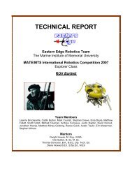
technical report - the Marine Advanced Technology Education (MATE)
technical report - the Marine Advanced Technology Education (MATE)
technical report - the Marine Advanced Technology Education (MATE)

Create successful ePaper yourself
Turn your PDF publications into a flip-book with our unique Google optimized e-Paper software.
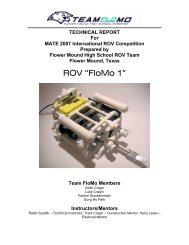
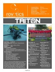
ROV PrinciplesStructureThe frame of any unit is <strong>the</strong> backbone and provides <strong>the</strong> strength of any project. When it comes toROV’s we first start off with <strong>the</strong> chassis. The chassis in work class ROV’s are made ofaluminum. O<strong>the</strong>rROV’s are made of different materials such as: plastics, steel, and o<strong>the</strong>rcomposites. TeamAZUL’s ROV is built with HDPE and offers a strong yet lightweight materialto build with. Please see Picture 1 below:Picture1BuoyancyThe success of any underwater endeavor rests on buoyancy. There are three different kinds ofbuoyancy. Negative buoyancy is when <strong>the</strong> object simply sinks to <strong>the</strong> bottom. Positive buoyancyis when an object tends to float and has a hard time sinking. Neutral buoyancy is when an objectstays in place at a certain depth. Team AZUL would like to design a unit that has a slightlypositive to neutral buoyancy factor. This will help at <strong>the</strong> sea bottom, by avoiding stirring up siltwhen <strong>the</strong> vehicle wants to come up. Also, if <strong>the</strong> ROV is ever cut loose, it ensures that it willeventually float to <strong>the</strong> surface.The ROV is being designed to operate at 65 feet, but will be built to safely overcome depths of100 feet. This would mean that it has to withstand 43.3 pounds per square inch:Page 6
Pressure = rgh= 1000kg/m³ x 9.81m/s² x 30.48mPressure = 299009Pa ≈ 43.3 psiBuoyancy is <strong>the</strong> tendency of a fluid to exert a supporting force (Buoyant Force) on a body placein <strong>the</strong> fluid. The equation for <strong>the</strong> Buoyant Force is:F b = g f V dF b Buoyant Forceg f Specific WeightV d Volume of fluid being Displaced by <strong>the</strong> objectWeight of <strong>the</strong> object must be calculated to know whe<strong>the</strong>r an object will sink or float:W o = m o gW o = weightof <strong>the</strong> objectm o = mass of <strong>the</strong> objectg = gravitational accelerationTo link Buoyancy Force equation to <strong>the</strong> Weight of <strong>the</strong> Object we need to have <strong>the</strong> SpecificWeight equation. Specific Weight of Fluid:g f = r f gg f = Specific Weightr f =density of fluidg = gravitational accelerationPage 7
The density equation is:r = Submarines and scuba divers depend on Neutral buoyancy to control <strong>the</strong>ir depth. NeutralBuoyancy is achieved when <strong>the</strong> weight of <strong>the</strong> body is exactly <strong>the</strong> same as <strong>the</strong> weight of <strong>the</strong>volume of <strong>the</strong> fluid displaced. To achieve neutral buoyancy:W o = F bTherefore:m o g = g f V dEquation of Density:r = Result is:m o g = V dgCanceling out leaves:m o =m fThe mass of <strong>the</strong> object must equal <strong>the</strong> mass of <strong>the</strong> fluid that it displaces to achieve neutralbuoyancy. However, for <strong>the</strong> Team Azul’s ROV, and most underwater vehicles of this nature,positive buoyancy is desired. This is in-case <strong>the</strong> vehicle comes undone from its te<strong>the</strong>r, it wouldsafely float to <strong>the</strong> surface and also <strong>the</strong> vehicle would not have to use its thrusters lifting from <strong>the</strong>sea floor, stirring silt.Team Azul’s ROV has <strong>the</strong> following buoyancy numbers displayed in Figure 1 below with <strong>the</strong>following stats:Page 8
Figure 1ThrustersAn ROV needs to be able to move around underwater, and for that we need propellers (oftencalled thrusters) which in turn need motors to drive <strong>the</strong>m. The choice of motor, and how we areto control <strong>the</strong>m, is key to <strong>the</strong> design of <strong>the</strong> propulsion system. Team AZULwas given/donated 3Seabotix BTD150 thrusters which have 18 N thrust each. We have planned for 4 thrusters in <strong>the</strong>horizontal plane and 1 in <strong>the</strong> vertical. This is approximately ¼ of our total power supply from<strong>the</strong> surface. This decision was made within <strong>the</strong> restrictions of using power between propulsion,video lights, sensors, and manipulator while still having a safety factori.e. so <strong>the</strong> electronics donot overheat etc. Please see Picture 2 of thruster below:Page 9
Picture 2ElectronicsWhen it comes to ROVs, one of<strong>the</strong> most important areas is <strong>the</strong> electronics and understanding itsfunctions. The te<strong>the</strong>ris <strong>the</strong> umbilical cord of<strong>the</strong> system, where all <strong>the</strong> information travels fromtopside controllers on<strong>the</strong> surfaceto <strong>the</strong> bottom-side ROV. Inside of a te<strong>the</strong>r are wires that carrypower, data, and different signalss to and from<strong>the</strong> controlcenter. If <strong>the</strong> te<strong>the</strong>r would ever detach<strong>the</strong> ROVwould be indanger of being lost ordamaged and is thus anarea that requires great carein designand implementation.Next is <strong>the</strong> control systems, this area consist of several different components such as<strong>the</strong> circuitboard andmicroprocessor etc. ROVs can have onboard control systems to manage differentelectricall areas.The video output andcontrol interface are also areas of great importance due to <strong>the</strong> fact thatprogramming is required. The underwater camera and lighting must work toge<strong>the</strong>r and onewithout <strong>the</strong> o<strong>the</strong>r is useless. TeamAZUL hasdedicated <strong>the</strong> limited surface power in such a way.Pls. See Table 1 below:Page10
System Power (Watts) =IV Total 1920 (Watts)Thrusters 410Electronics/Tools 420Manipulator 350Video lights 100Camera 140Safety Factor 500Table 1ToolsROVs can have <strong>the</strong> ability to complete different task that in some cases might be impossible forhumans to do. ROVs are known to have several tools onboard for various applications. TeamAzul, with its modular design, is built as to add various sensing equipment.Sonar is very popular as it can be used to map <strong>the</strong> seafloor in order to find lost items and alsoserve as a second set of eyes for <strong>the</strong> ROV in case visibility is reduced, making <strong>the</strong> onboardcamera system deficient. (Pls. see Picture 3 for sample sonographic image representing a brokenship on <strong>the</strong> seafloor.)Metal detection is also very helpful as it can be used to follow a pipeline that might be buried in<strong>the</strong> ground for inspection. A magnetometer is a scientific instrument used to measure <strong>the</strong> strengthand/or direction of <strong>the</strong> magnetic field in <strong>the</strong> vicinity of <strong>the</strong> instrument. These devices can greatlyaid in locating lost tools and undersea items for <strong>the</strong> ROV. Team Azul is using a simple versionof this tool in its modular design to assist with ROV instrumentation capabilities. Port # 9 hasbeen assigned to transmit <strong>the</strong> information to <strong>the</strong> ROV processor for this task.An Infrared Radiometer is used to sense <strong>the</strong>rmal differences on <strong>the</strong> seafloor bottom. Thisinstrument can give <strong>the</strong> ability of locating anything with a heat signature underwater such as aleaking oil pipeline and operating machinery. (Pls. see Picture 4 of a leaking oil pipelineunderwater.)Page11
Team Azul, as of Dec 5, 2010 has only been able to acquire a magnetometerand is still talking todifferent vendors met at <strong>the</strong> MTS meeting on Oct 28, 2010 to gain o<strong>the</strong>r sensor packages.Picture 3 Picture 4ROV MarketsThe primary market for ROVs is in <strong>the</strong> offshore Oil and Gas industry, roughly 85% of <strong>the</strong>market. Telecommunications, who have 14% market share, mainly employing ROVs to assist in<strong>the</strong> laying of trans-oceanic cable. Scientific and academic research, though it is <strong>the</strong> public’sprimary exposure to ROVs, makes up less than 1% of <strong>the</strong> market. The market for ROV’s israpidly growing. According to <strong>the</strong> Douglass-Westwood industry <strong>report</strong>, “<strong>the</strong> attrition of <strong>the</strong>existing fleet will require over 550 new work-class units over <strong>the</strong> next five years – driven by <strong>the</strong>industry’s push into deepwater and <strong>the</strong> increased necessity of work-class ROVs intoday’sindustry.” Please see Graph 1 below to understand <strong>the</strong> growing ROV market.Page12
Graph 1Picture 5Page13
Class DistinctionsGeneral-class ROVs are usually one to two feet in width and height and generally two to threefeet long. The most common thruster configuration is four horizontal and one vertical, all fixed.They are primarily used for inspection of offshore structures as well as diver aid. However, <strong>the</strong>ycan be used in many cases for light work and some heavy work with certain payloads orattachments. This class is a popular size for science and research, as it is capable of carrying asizeable payload while still retaining <strong>the</strong> inherent efficiency of a fully-electric ROV design.(Please see Picture 5above &Picture 6 below)Picture 6Commercial DesignsThere are two main commercial designs that Team AZUL’s ROV is comparable to: <strong>the</strong> SeaeyeFalcon and <strong>the</strong> Sub-Atlantic Mohawk. (Please see Picture 4 & 5) The Falcon measures 1.6 feethigh, 2 feet wide, and 3.2 feet long. It weighs 110 pounds with a 19-pound payload, can dive to980 feet, and its frame is polypropylene. It is also equipped with a single-function manipulatorand can field a five-function manipulator as an additional payload. The Mohawk is similar in sizeto <strong>the</strong> Falcon (2 ft x 2.5 ft x 3.1 ft), but due to its traditional construction and aluminum frameweighs 364 pounds. This additional weight translates into a heavier payload capacity at 77Page14
pounds. A manipulator is not included in <strong>the</strong> basic design but can be added via a tool skid. TheMohawk can dive to 3,280 feet. Ano<strong>the</strong>r design to be considered was constructed privately byone Ed Jacobs. Similar in specification to <strong>the</strong> Falcon and with a reduced dive depth of 300 feet,it is a fraction of <strong>the</strong> cost. Close inspection of this design will hopefully lower <strong>the</strong> team’s pricepoint. Please see Picture7 below.Picture 7Price Ranges“Mini”-class observation ROVs run from $5,000 to $10,000, but <strong>the</strong>ir capabilities are limited by<strong>the</strong>ir small size. Larger observation ROVs (in <strong>the</strong> general-class range) are manufactured with ahydrodynamic shell and have <strong>the</strong> ability to cover an exceedingly large area of ocean. However,because <strong>the</strong>ir advanced design, <strong>the</strong>y are also extremely expensive - $55,000 to $500,000 withoutoptions. The general class ROVs described above are $125,000 and $100,000 for <strong>the</strong> Falcon andMohawk, respectively. The “Jacobs” ROV is only $5,000, and it is because of this design’scompromise between features and affordability that our budget is approximately $20,000.Page15
ScopeScope of WorkTeam AZUL's goal is to make a hybrid ROV; one with which Team Azul can enter <strong>the</strong> <strong>MATE</strong>competition in June 2011 and <strong>the</strong>n use it in commercial applications. The ROV is beingdesigned and built to exceed competition requirements. The team is designing an ROV thatwould be a ‘modular' in design, in which one is able to add/subtract parts easily, such as aninfrared radiometer, which would give <strong>the</strong> ROV a dual purpose. This type of multi-usage willpresent challenges in such a project, along with lack of knowledge about <strong>the</strong> 2011 <strong>MATE</strong>requirements, because <strong>the</strong>y have been published much after <strong>the</strong> team has designed and built itsROV. The team carefully looked over past requirements and guessed that a 3 axis of motionspatially controlled arm would be required to be built versus a rate manipulator arm -<strong>the</strong>difference is that <strong>the</strong> first responds in real time to master control whereas <strong>the</strong> second onlyresponds to on/off commands in a given axis. However, due to funding limits and a change in<strong>the</strong> <strong>MATE</strong> competition requirements, no such arm was built; instead, a host of ‘finger’ toolswere designed to deal with <strong>the</strong> upcoming specifications. If <strong>the</strong> vehicle is grounded or <strong>the</strong> objectthat it was trying to retrieve, <strong>the</strong> ROV will be physically pulled out of <strong>the</strong> water (with <strong>the</strong> objectattached) by its reinforced te<strong>the</strong>r. The ROV will also encompass a number of sensors for leakdetection, sonar, and metal detection and vendors will be actively pursued for donations.Gantt ChartOur Gantt Chart at this point is fairly straight-forward and simple. We have three stages ofwhich <strong>the</strong> first one is Planning. The second stage is research & development which includesframe design and analysis. Designing and testing along with fundraising and materialfinalization, was set to be completed by June 1. However, due to financial restraints and poorfundraising in down economy, Team Azul was unable to meet its financial targets. The ROVspecifications needed to be finalized by this date so production could start, and this delay hascaused all o<strong>the</strong>r tasks to be postponed. At <strong>the</strong> time of writing this <strong>report</strong>, Dec 5, 2010 our designis 100% complete and we have built <strong>the</strong> prototype and final version of <strong>the</strong> ROV. The finaldesign of <strong>the</strong> vehicle is complete with only minor ‘tweaking’ needed. During <strong>the</strong> summer, TeamAZUL was able to work heavily on <strong>the</strong> control/electrical systems of <strong>the</strong> ROV. This work, oftenPage16
difficult, because of <strong>the</strong> lack of understanding mechanical engineers have in electrical aspects,was still completed due to great overall team effort. The manipulator arm was never fullydesigned or worked on due to budget constraints. This may have been a blessing in disguisebecause <strong>the</strong> <strong>MATE</strong> 2011 competition does not require a manipulator arm, only non-movabletools such as a grip and saw. However, one is still planned to be designed and built to pursue <strong>the</strong>commercial aspect of <strong>the</strong> ROV. Final submission of <strong>the</strong> project, including a completed <strong>report</strong>, isscheduled for December 7, 2010.Past IssuesTeam AZUL carefully looked at what o<strong>the</strong>r teams had done and where <strong>the</strong>y failed. This wasdone to develop a winning strategy by avoiding previous pot-holes. One of <strong>the</strong> very first thingswe studied as a team was potential pitfalls. Team AZUL found out that, in <strong>the</strong> past, mechanicalengineers have had many problems with <strong>the</strong> electrical control aspect of <strong>the</strong> ROV, such asoverloading <strong>the</strong> control systems –this was validated this summer when <strong>the</strong> team was building <strong>the</strong>control systems. Also, ano<strong>the</strong>r team that entered <strong>the</strong> <strong>MATE</strong> competition with a perfectly runningROV was unable to sink down to <strong>the</strong> bottom due to excessive positive buoyancy. This inabilityof <strong>the</strong> ROV to sink forced <strong>the</strong> team out of <strong>the</strong> competition. Some of <strong>the</strong> critical issues that canprevent Team AZUL from entering into competition are electrical, buoyancy, and teammanagement issues that have plagued previous teams.Page17
Risk AnalysisA preliminary risk assessment was done by Team AZUL to see what potential problems wecould plan for. A Risk Analysis template was found at <strong>the</strong> McCombs School of Business for afeasibility study done on an aircraft project. The format used helped us identify many internaland external threats and <strong>the</strong>n helped us assess <strong>the</strong> risk associated with <strong>the</strong>m. One of <strong>the</strong> firstareas <strong>the</strong> team assessed was External Risk; this is defined as what factors damage or delay <strong>the</strong>project. For Team AZUL, advice, parts, and fundraising were from outside sources and thusposed potential threats. With such important considerations as parts and advice being dependenton outside sources, Team AZUL still considered <strong>the</strong>se low threat or risk factors, arguing that ifone supplier or advisor failed ano<strong>the</strong>r could always be found. Fundraising was also deemed alow threat, given <strong>the</strong> extensive presence of <strong>the</strong> offshore oil and gas industry in Houston. Thisconcept would be hard to appreciate, and we expected skepticism from our audience during <strong>the</strong>presentation. (This topic will be more thoroughly discussed in Fundraising.) Also, ourManagement Risk is extremely high because any project will fail (and many have) due to thisinability. Our overall risk assessment is scored at 7 out of 10 which is High risk project.BudgetA preliminary budget was developed which shows <strong>the</strong> costs of necessary parts and travel for <strong>the</strong><strong>MATE</strong> competition. This budget considers <strong>the</strong> various goals Team AZUL is trying to achieve.Some of <strong>the</strong> items/materials are essential to building and operating <strong>the</strong> ROV (listed in yellow)such as thrusters and te<strong>the</strong>r. O<strong>the</strong>rs items, such as radiometer and sonar are parts that Team Azulrequires to make this vehicle commercially viable, but not necessarily vital. The total budgetwas estimated to be $15,000 (Please see Budget 1) some of which is collected through materialsor donations.Page18
Budget 1As of Dec. 5, 2010 our budget and donations stand at much different amounts thananticipated. This may be due to <strong>the</strong> weak economy where vendors are less likely to contributedue to <strong>the</strong>ir bottom-line. We initially had very positive results from companies such asOceaneering and Schilling Robotics, but <strong>the</strong>se initial contacts were reluctant to pursue anygrants. However, thanks to Exclusive Wireless and SI Technologies we were able to cover <strong>the</strong>shortfall in funding and our budget stands as <strong>the</strong> following. Some of <strong>the</strong> donations were used inpurchasing parts again to cover mistakes in design, such as in having to purchase an additionalAduino CPU because <strong>the</strong> initial one could not handle <strong>the</strong> load. O<strong>the</strong>r items had to be purchasedagain, such as <strong>the</strong> electronic boxes because of our repeated mistakes in drilling watertight seals.Please see Budget 2 table for financial details.Page19
Items Quantity Cost $Thrusters 5 2500Te<strong>the</strong>r 1 900Control System (PLC) 1 725Frame Material 2 320Camera 2 270Building Material 360Power Supply 110Coating/Paint 1 200Arm 1 500Infrared Radiometer 1 800Metal Detector 1 300Sonar 1 600Total Cost ($) 7585Donations (Money) 2500Donations (Parts) 2985Still Needed ($) 2100Budget 2Team Azul will have to vigorously pursue funding to make up for <strong>the</strong> shortfall in <strong>the</strong> budget.$2100 are still needed to purchase <strong>the</strong> sensing equipment needed to make <strong>the</strong> ROV trulycommercially-viable.Page20
Funding StrategyInitially, Team Azul was contacting <strong>the</strong> larger offshore industries such as Halliburton and Shellto acquire funds for <strong>the</strong> project. After receiving a lukewarm response and failing to raise anyfunds in a three month period, we decided to target small to mid-size businesses. A brochurewas developed to present to <strong>the</strong>se companies. (Please see Brochure 1 below.) With <strong>the</strong>sebrochures and <strong>the</strong> new initiative to contact local companies versus larger more inaccessible ones,and involve <strong>the</strong>m with <strong>the</strong> College of <strong>Technology</strong>, Team Azul was able to immediately raise$1500. This strategy has returned much better results in <strong>the</strong> short time it has been used.Brochure 1Page21
Design AnalysisFrame Design ComparisonThree designs were considered, and <strong>the</strong>y are described below.Design ADesign A was <strong>the</strong> first design considered; it is a typical mini-class ROV. All electronicsand drive circuits are encased in a plastic enclosure extending <strong>the</strong> length of <strong>the</strong> vehicle, withthrusters mounted to <strong>the</strong> outside. A 3-thruster configuration, design A would use two thrustersfor forward/reverse propulsion, mounted on <strong>the</strong> skids, with a third thruster mounted at 45 degreesto <strong>the</strong> vertical to facilitate movement up and down in <strong>the</strong> water column. While this streamlineddesign would provide exceptional speed and low drag, maneuverability is compromised by <strong>the</strong>thruster configuration. Also, <strong>the</strong>re is little room for expansion or additional equipment, which isincompatible with <strong>the</strong> main goal of Team Azul to provide a multi-purpose hybrid platform.Page22
Design B was <strong>the</strong> next iteration in Team Azul’sdesign process. This larger ROVincorporates many more elements of <strong>the</strong> general-class design, and <strong>the</strong> open frame offersadditional versatility. Unfortunately, this frame was designed with aluminum or steel in mind,and thus is joined by welds. Due to <strong>the</strong> size of <strong>the</strong> frame, coupled with <strong>the</strong> densities of <strong>the</strong>aforementioned substances, it was decided that <strong>the</strong>rmoplastics would be a much betteralternative. This design would not be feasible without an extraordinary amount of epoxy to gluetoge<strong>the</strong>r <strong>the</strong> ¾” members.Design BPage23
This is <strong>the</strong> final working design chosen by Team Azul. Known as design “C,” it isbelieved that this frame will offer <strong>the</strong> best compromise between a low drag coefficient, versatileopen-frame design, maneuverability, cost, and weight. The frame is designed so that it may beconstructed in its entirely from one 3’ by 2’ sheet of plastic, and <strong>the</strong> supporting members cut outfrom <strong>the</strong> larger sections, saving on material. These sections will <strong>the</strong>n be bolted, riveted, oro<strong>the</strong>rwise fastened toge<strong>the</strong>r.Design CPage24
Robotic ArmThe requirement was established for a 3-axis robotic arm, and several methods wereconsidered to solve this problem. Ultimately, traditional solutions involving servo motors ateach joint were eschewed in favor of <strong>the</strong> following design, developed by undergraduate assistantJessica Fletcher. This design works by <strong>the</strong> actuation of several sets of steel cables in a “tendon”-configuration. This arm will most likely be machined out of aluminum; this, coupled with <strong>the</strong>high breaking strength of <strong>the</strong> cables, will mean <strong>the</strong> primary determination of strength in this partof <strong>the</strong> ROV will be <strong>the</strong> three servo motors used to drive <strong>the</strong> arm. These motors will be mountedwithin <strong>the</strong> ROV, near <strong>the</strong> base of <strong>the</strong> arm (not shown).Page25
As can be seen in <strong>the</strong> previous illustration, <strong>the</strong> steel cables attached to hardpoints outsideof <strong>the</strong> arm are wrapped around spools which are <strong>the</strong>n rotated to move <strong>the</strong> arm across <strong>the</strong> x-z or y-z planes. The center of <strong>the</strong> arm shaft is hollow to allow three additional cables to actuate <strong>the</strong>gripper fingers, which are held open by a set of springs.During <strong>the</strong> course of <strong>the</strong> semester, <strong>the</strong> idea to build a manipulator was dropped due tofunding issues and o<strong>the</strong>r constraints. Also, <strong>the</strong> <strong>MATE</strong> competition requirements do not requireone, so <strong>the</strong> plan was not pursued as actively as control systems or propulsion –key componentsof <strong>the</strong> ROV. Plans are in place to utilize non-moveable tools such as a saw and clip to meet<strong>MATE</strong> requirements and plans of building a manipulator are put on hold till funding and interestcan be found.Page26
Material Density and Thrust-to-Weight RatioGiven <strong>the</strong> preliminary data, a full complement of SeabotixBTD150 thrusters will be used– this will provide vectored thrust along <strong>the</strong> x-y plane. The following table calculates <strong>the</strong> thrustvectors, which are at 45-degree angles to <strong>the</strong> thrusters as mounted on <strong>the</strong> chosen frame design.This table (Pls. see Table 2) shows <strong>the</strong> calculations of <strong>the</strong> thrust-to-weight ratios of <strong>the</strong>last two iterations of Team Azul’s designs. Designs “B” and “C” were initially designed with atotal footprint of 3’ by 2’ by 1.5’ to fulfill competition requirements while remaining in <strong>the</strong> samesize class as competing general-purpose ROVs. However, <strong>the</strong> subsequent mass of <strong>the</strong>appropriately-sized frame was too much for <strong>the</strong> Seabotix thrusters to handle effectively.Afterwards, both <strong>the</strong> “B” and “C” designs were scaled down to 75% of <strong>the</strong>ir original size. Thedata below will reveal <strong>the</strong> evolution to an adequate design.Of <strong>the</strong> two plastics contemplated, High-Density Polye<strong>the</strong>lene (or HDPE) was chosen overABS plastic simply because of its slightly superior performance. If <strong>the</strong>re are any problemsencountered with HDPE, ABS provides a ready alternative due to its similar characteristics.Material Properties Design AMaterialYieldStrength(Mpa)TensileStrength(Mpa) Density(Kg/m^3)Volume ofFrame(m^3)mass ofFrame(kg)density ofwater(kg/m^3)Weight of Framein Water(N)Al 2014 97 2800 0.017156 48.04 1027 298.40HDPE 22.06 31.37 950 0.017156 16.30 1027 ‐12.96ABS 29.64 1024 0.017156 17.57 1027 ‐0.50PTFE 23 25 2158 0.017156 37.02 1027 190.35Scaled Down FrameAl 2014 97 2800 0.0072 20.16 1027 125.23HDPE 22.06 31.37 950 0.0072 6.84 1027 ‐5.44ABS 29.64 1024 0.0072 7.37 1027 ‐0.21PTFE 23 25 2158 0.0072 15.54 1027 79.88Material Properties Design BMaterialYieldStrength(Mpa)TensileStrength(Mpa) Density(Kg/m^3)Volume ofFrame(m^3)mass ofFrame(kg)density ofwater(kg/m^3)Weight of Framein Water(N)Al 2014 97 2800 0.0068 19.04 1027 118.27HDPE 22.06 31.37 950 0.0068 6.46 1027 ‐5.14ABS 29.64 1024 0.0068 6.96 1027 ‐0.20PTFE 23 25 2158 0.0068 14.67 1027 75.45Scaled Down Frame(75% of Original Size)Al 2014 97 2800 0.0028 7.84 1027 48.70HDPE 22.06 31.37 950 0.0028 2.66 1027 ‐2.12ABS 29.64 1024 0.0028 2.87 1027 ‐0.08PTFE 23 25 2158 0.0028 6.04 1027 31.07Page27
Thrust to Weight Ratio Design AMaterial mass of ROV (kg) mass of components (kg) total mass (kg) Weight Thrust to weightAl 2014 750.4 3.56 753.96 7396.35 0.01HDPE 256.6 3.56 260.16 2552.17 0.02ABS 274.43 3.56 277.99 2727.08 0.02PTFE 578.34 3.56 581.90 5708.44 0.01Scaled down Frame(75% of original size)Al 2014 317.52 3.56 321.08 3149.79 0.02HDPE 107.73 3.56 111.29 1091.75 0.06ABS 116.12 3.56 119.68 1174.06 0.05PTFE 244.72 3.56 248.28 2435.63 0.03Thrust to Weight Ratio Design BMaterial mass of ROV (kg) mass of components (kg) total mass (kg) Weight Thrust to weightAl 2014 19.04 3.56 22.60 221.71 0.28HDPE 6.46 3.56 10.02 98.30 0.63ABS 6.96 3.56 10.52 103.20 0.60PTFE 14.67 3.56 18.23 178.84 0.35Scaled down Frame(75% of original size)Al 2014 7.84 3.56 11.40 111.83 0.55HDPE 2.66 3.56 6.22 61.02 1.01ABS 2.87 3.56 6.43 63.08 0.98PTFE 6.04 3.56 9.60 94.18 0.66Page28
ProE CalculationsAfter frame “C” was chosen, analyses were run in ProEngineer software to simulate a 20lb load upon <strong>the</strong> top bar of <strong>the</strong> frame, leaving <strong>the</strong> bottom constrained, to test <strong>the</strong> basic structuralstability of <strong>the</strong> frame. These results are shown below, are summarized by <strong>the</strong> result that totalstress on <strong>the</strong> frame did not exceed 303 psi, well within <strong>the</strong> yield stress limits for HDPE(MaroPolymer). Also included are graphs of stress, displacement, and strain along <strong>the</strong> outer edge of <strong>the</strong>ROV frame. Please see Figure 2.Fig. 2Page29
Fig 3Fig 3: (Above) Von Mises Stresses are tolerable by our choice of HDPE frame material. Along<strong>the</strong> ‘path of curve’ of our testing, all VMS stayed within predicted range. Safety margin of 2 wascalculated within <strong>the</strong> testing parameters.Fig 4: (Below) Displacement amounts are within range with <strong>the</strong> HDPE frame material. Safetymargin of 2 was calculated within <strong>the</strong> testing parameters and <strong>the</strong> material movement was still notnoticeable.Fig 5: (Below) Strain numbers are within range with <strong>the</strong> HDPE frame material. Safety margin of2 was calculated within <strong>the</strong> testing parameters and <strong>the</strong> material has allowance for much greaterstrain capacity.Page30
Fig4Fig5Page31
Thermal CalculationsThermal calculations were conducted to see how much heat would have to be dissipated from <strong>the</strong>H-bridges and microprocessor, from within <strong>the</strong> electronic control boxes, before <strong>the</strong> temperaturebecame disruptive. A minimum of 0.02m 2 was required to dissipate <strong>the</strong> heat generated fromwithin in <strong>the</strong> control boxes to keep <strong>the</strong> CPU and H-bridges running. Please See Diagram 1below.Diagram 1Control SystemThe control system in use is defined by <strong>the</strong> diagram below. The ROV will be controlledwith a SNES powered controller interfaced with anArduino CPU. The SNES running on <strong>the</strong>surface (topside) connected to <strong>the</strong> bottomside with <strong>the</strong> CPU will be twisted pair serial cableswhich run through <strong>the</strong> te<strong>the</strong>r, sending control signals through <strong>the</strong> CPU to <strong>the</strong> individual motorH-bridge controls and Omron relay. The CPU will also handle signals from simple sensors suchas <strong>the</strong> metal detector; more complex imaging devices, such as <strong>the</strong> sonar system, will be routedseparately through a higher-resolution interface directly to <strong>the</strong> surface. The H-bridges in questionwill be 4 parallel pairs of L298N devicesused to operate at higher frequency and more precise tobe multi-directional. The Omron relay G5RL1A to control <strong>the</strong> onboard motors is a singledirection SPST –single pole single through relay. (Pls. see Fig. Zuchlewski)Note: Please See Appendix ‘Operating Manuel’ for details on circuit configuration andcalculations.Page32
CPU will use E<strong>the</strong>rnet for control and communication. This inexpensive and versatilecable can be wrong long distance, but offers dependability, with little signal loss, in short runs.An embedded web server can allow for real time data acquisition. This data is mainly for <strong>the</strong>video feedback and o<strong>the</strong>r tools <strong>the</strong> team is to place on <strong>the</strong> ROV. Data from <strong>the</strong> server can bestreamed real time to a website including video, sensor, and coordinates. This is important so <strong>the</strong>driver can make real time decisions on direction and things of interest. The five motors will becontrolled by <strong>the</strong> SNES controller by <strong>the</strong> Arduino CPU, which controls <strong>the</strong> pathways. Thecontrol signals and <strong>the</strong> ampageis given by <strong>the</strong> CPU, which will be used to control <strong>the</strong> forwardand reverse movement. If <strong>the</strong> control signal from <strong>the</strong> CPU is 01 <strong>the</strong>n Motor1 will be activated.And accordingly if a control signal 11 is sent from <strong>the</strong> CPU <strong>the</strong>n Motor2 is activated.Page33
The two H bridges can only handle 4 amps each. Two 4 amps circuit creates an 8 ampsparallel circuit. The first is 5 V and <strong>the</strong> second is 20 V. The Logic Power eliminates <strong>the</strong> noisewithin <strong>the</strong> system, this is done so <strong>the</strong> circuit is not disturb and automatically breaks due tovibrations. Using Pulse Width Modulation (PWM), an Average voltage can be simulated to <strong>the</strong>H-bridges. The CPU will output PWM to <strong>the</strong> H-bridge circuit to control motor speed.Temperature sensors are placed next to <strong>the</strong> motor and in <strong>the</strong> water to limit <strong>the</strong> efficiency of <strong>the</strong>motor. This is done to prevent a blowout of <strong>the</strong> motor and circuits.CMOS 4201 controller transmits and receives data serially to and from <strong>the</strong> CPU. The CPUsends a latch when ready for RX, <strong>the</strong> first bit is TX via data out. CPU sends 15 clocks pulses for<strong>the</strong> remaining 15 bit, which is computes data in microseconds. The CPU outputs commands toH-bridge.Please See Appendix ‘Operating Manuel’ for details on circuit configuration andcalculations.Page34
Build & TestingAttempt I:The first prototype was constructed October 8 out of a wooden frame by Team member Walterand electronic control boxes were constructed to control <strong>the</strong> 3 donated Seabotix motors. (Pls.see Picture 7) Sealing <strong>the</strong> electronic boxes was of vital concern, which was not properly done.The electronic boxes were sealed using silicon and were breached by <strong>the</strong> water damaging wiringand H-bridges. This could have not have been anticipated, due to <strong>the</strong> veracity with which<strong>technical</strong> advice was given by a known ROV builder. One fault may have been <strong>the</strong> unusuallylarge amount of silicon used to seal cable inlets into <strong>the</strong> electronic boxes of which <strong>the</strong> interior ofmay have never dried and sealed properly. Ano<strong>the</strong>r was <strong>the</strong> inflexibility of <strong>the</strong> silicone, whenattached between metal boxes and flexible cables, <strong>the</strong> silicone always seemed to ‘give’ a little,allowing for possible water leaks. In <strong>the</strong> process of opening and resealing <strong>the</strong>se electronic boxes,a few of <strong>the</strong> screws were stripped and new boxes had to be purchased. Salvaging <strong>the</strong> old boxeswas initiated, but <strong>the</strong> screws were so worn out by <strong>the</strong> end that new ones were necessary toprecede fur<strong>the</strong>r.Picture 7Attempt II:By November 17 <strong>the</strong> team realized that water breach of <strong>the</strong> electronic boxes was a majorobstacle to overcome and this must be achieved for survival of <strong>the</strong> ROV program. ImmediatelyBLUE SEA SYSTEMS ‘CableClam Waterproof Through-Deck Fittings’ fittings were orderedfor $173 to tackle <strong>the</strong> leak issue (Pls. see Picture 8 & 9). These connectors were ordered forovernight delivery and came with excellent reviews by <strong>the</strong> ROV building community. Eachseparate cable that was going into <strong>the</strong> electronic boxes was given a watertight seal ‘CableClam’and additional one for <strong>the</strong> te<strong>the</strong>r one. These ‘CableClam’ connectors work by drilling into <strong>the</strong>electronic boxes to attach a watertight foundation. Once this is in place, a rubber cork is drilledPage35
just enough for passing <strong>the</strong> cablethrough andano<strong>the</strong>r fitting seal screwed into <strong>the</strong> foundationnfitting to keep everything in place. This system worked perfectly under ‘sink’ tests, but failedwhen once again <strong>the</strong> metal electronic boxes were breached through <strong>the</strong> stripped screws in <strong>the</strong>new boxes. Also <strong>the</strong>box tops were assumedto be watertight, as mentioned by <strong>the</strong> manufacturer,but waterleaked quickly throughh <strong>the</strong> tops. All systems would fail and would have to be rewiredwith newH-bridges once <strong>the</strong> water breached<strong>the</strong> electrical boxes. Our $102 SM5100B cellphone controller chip(cellular shield), a device that would allow control of our ROV throughhcell phones, was ruined by such a water breach. Our prototype was made from wood and weover-waited for our HDPE material to arrive –requiring multiple phone calls with<strong>the</strong> vendorfortimely delivery. At this time we had to change our initial circuit unitfrom a multiplexor to anArduino because <strong>the</strong> multiplexorwas not handling <strong>the</strong> load and processing quickly enough.Wiring <strong>the</strong> ROV wasa huge challenge due to<strong>the</strong> lack ofelectrical experience mechanicalengineershave.Picture 8Picture 9Attempt III: Final BuildBy November 30, 2010 <strong>the</strong> HDPE frame wascut and built and new electrical boxes without anystripped screws capping <strong>the</strong> top were attached to <strong>the</strong> frame. (Pls. seee Picture 10, 11, 12)‘CableClam’ connectors were used to attach all cables and te<strong>the</strong>r lineand <strong>the</strong> ROV was tested inpool conditions at a depth of 8 feet. Video Cameras were attached in<strong>the</strong> front and back of <strong>the</strong>ROV per<strong>MATE</strong> competition requirements and <strong>the</strong> videoline was run up <strong>the</strong> te<strong>the</strong>r line. Theteam wasprepared with previouswater leaksand this time used newelectrical boxes with newscrews. Just to be cautious, <strong>the</strong> caps were sealed with a thin layer ofsilicone gel. The HDPEframe was sturdy andlight and offered easy drilling for <strong>the</strong> modular design –parts could beattached and removed with ease. ‘CableClam’ connectors were verified for sealing ability alongwith <strong>the</strong> tops.Page36
The test was a success with all <strong>the</strong> recent changes. Electrical boxes did not leak water damaging<strong>the</strong> H-bridges or Arduino processor. The ‘CableClam’ connectors held up along with <strong>the</strong> boxtops to prevent water from breaching in. The sturdy HDPE frame was able to gently float around<strong>the</strong> pool and was very maneuverable. One issue was <strong>the</strong> control of <strong>the</strong> buoyancy and this wasattributed to not calculating for fresh water pools adequately. Ano<strong>the</strong>r reason may have been notgetting <strong>the</strong> exact material we had ordered and its density not being <strong>report</strong>ed. For future changeswe would have to recommend a buoyancy control device be added to <strong>the</strong> ROV and notcompletely be dependent on vertical thrust motors; however, <strong>the</strong> test and <strong>the</strong> final build was asuccess.Picture 10Picture 11Picture 12Page37
ConclusionIn conclusion, Team Azulhas constructed a viable ROV for commercial and competitiveuse. Fur<strong>the</strong>r considerations include more ProEngineer stress calculations to optimize <strong>the</strong> framedesign, as well as computational fluid dynamics analysis to study <strong>the</strong> ROV’s in-watercharacteristics. Also, <strong>the</strong> behavior of all considered materials in saltwater must also be studied, toavoid corrosion and stress cracking issues. With all that has been taken into consideration <strong>the</strong>ROV is now famously referred to <strong>the</strong> B.O.S.S. The Buoyant Open-Architectural SubmersibleSystem (B.O.S.S.) is <strong>the</strong> ROV that will be used in <strong>the</strong> 2011 <strong>MATE</strong> competition.Page38
ReferencesDesign of an ROV – Brundage, H.M. et al. Oceans 2006 , Page(s): 1 – 5<strong>Marine</strong>buzz.comwww.longbeachdive.com/images/rov-controls-2.gif&imgrefurlhttp://www.rov.org/info.cfmhttp://www.angelfire.com/sc/cuttermorris/page103rovplans.htmlDynamic buoyancy control of an ROV - Wasserman, K.S. et al. Oceans 2003 , Page(s): SP2888 -SP2893 Vol.5www.gearfuse.com/.../ uploads/2007/09/rov-kit.jpg=ST pic 1http://www.ecophotoexplorers.com/ssrepublic.asphttp://www.offshore-technology.com/contractor_images/eca/3-rov.jpghttp://www.stormcable.com/pages.asp?ID=3http://www.videoray.com/images/picture/131PPT_New.jpghttp://www.flickr.com/photos/jjackowski/3815505579/http://www.scoop.co.nz/stories/PO0908/S00231.htmFrank P.Incropera, David P. DeWitt Fundamentals of Heat and Mass Transfer 6th ed Wiley,2007Dr. John Halkyard. “Hydromechanics of underwater vehicles: Resistance and Propulsion” ArtecOffshore Corp., Intervention Tutorial, March, 1989John C. Kuhn. “Resistance, Propulsion, and Maneuvering Model Testing” Arctec OffshoreCorporation, March 1986Roderick A. Barr. “Assessment of controllability and maneuverability of ROV’s and AUV’s”<strong>Marine</strong> <strong>Technology</strong> NFK Engineering, Oct 1985Maro Polymer Online. “Physical Properties of HDPE.”http://www.maropolymeronline.com/Properties/HDPE%20Prop.aspZuchlewski, Nick. “Explanation of ROV Control Systems.” See Appendix.Page39
AppendixPage40