construction and installation guidelines - pavliks.wcm - Web Content ...
construction and installation guidelines - pavliks.wcm - Web Content ...
construction and installation guidelines - pavliks.wcm - Web Content ...

You also want an ePaper? Increase the reach of your titles
YUMPU automatically turns print PDFs into web optimized ePapers that Google loves.
CONSTRUCTION AND INSTALLATION GUIDELINES<br />
DECKING INSTALLATION<br />
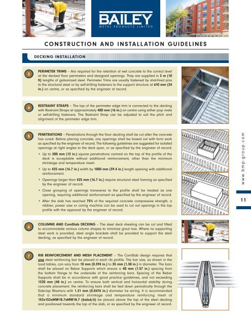
3<br />
PERIMETER TRIMS – Are required for the retention of wet concrete to the correct level<br />
at the decked floor perimeters <strong>and</strong> designed openings. They are supplied in 3 m (10<br />
ft) lengths of galvanized steel. Perimeter Trims are usually fastened by shot-fired pins<br />
to the structural steel or by self-drilling fasteners to the support structure at 610 mm (24<br />
in.) on centre, or as specified by the engineer of record.<br />
4<br />
RESTRAINT STRAPS – The top of the perimeter edge trim is connected to the decking<br />
with Restraint Straps at approximately 400 mm (16 in.) on centre using either pop rivets<br />
or self-drilling fasteners. The Restraint Strap can be adjusted to suit the pitch <strong>and</strong><br />
alignment of the perimeter edge trim.<br />
5<br />
PENETRATIONS – Penetrations through the floor decking shall be cut after the concrete<br />
has cured. Before placing concrete, any openings shall be boxed out with form work<br />
as specified by the engineer of record. The following <strong>guidelines</strong> are suggested for isolated<br />
openings at right angles to the deck span, or as specified by the engineer of record:<br />
• Up to 300 mm (12 in.) square penetrations centred on the top of the profile of the<br />
deck is acceptable without additional reinforcement, other than the minimum<br />
shrinkage <strong>and</strong> temperature mesh.<br />
• Up to 425 mm (16.7 in.) width by 1000 mm (39.4 in.) length opening with additional<br />
reinforcement.<br />
• Openings larger than 425 mm (16.7 in.) require structural steel framing as specified<br />
by the engineer of record.<br />
• Close grouping of openings transverse to the profile shall be treated as one<br />
opening, requiring additional reinforcement as specified by the engineer of record.<br />
• After the slab has reached 75% of the required concrete compressive strength, a<br />
nibbler, power saw or coring machine can be used to cut out openings in the top<br />
profile with the approval by the engineer of record.<br />
www.bmp-group.com<br />
11<br />
6<br />
COLUMNS AND ComSlab DECKING – The steel deck sheeting can be cut <strong>and</strong> fitted<br />
to accommodate various column shapes to minimize grout loss. Where no supporting<br />
steel work is provided, steel angle brackets shall be provided to support the steel<br />
decking, as specified by the engineer of record.<br />
7<br />
RIB REINFORCEMENT AND MESH PLACEMENT – The ComSlab design requires that<br />
one steel reinforcing bar be placed in each rib profile. The bar size, as shown in the<br />
load tables, can vary from 10 mm (0.394 in.) to 35 mm (1.38 in.) in diameter. The bars<br />
shall be placed on Rebar Supports which ensure a 40 mm (1.57 in.) spacing from<br />
the bottom flange to the underside of the reinforcing bars. Spacing of the Rebar<br />
Supports shall be in accordance with good practice <strong>guidelines</strong>, <strong>and</strong> not exceeding<br />
1220 mm (48 in.) on centre. To ensure both vertical <strong>and</strong> horizontal stability during<br />
concrete placement, the reinforcing bars shall be tied down periodically through the<br />
Side-lap Washers with 1.21 mm (0.0476 in.) diameter tie wiring. It is recommended<br />
that a minimum st<strong>and</strong>ard shrinkage <strong>and</strong> temperature reinforcing mesh of<br />
152x152xMW18.7xMW18.7 (6x6x6/6) be placed above the top of the steel decking<br />
<strong>and</strong> positioned towards the top of the slab, or as specified by the engineer of record.