MIDI Manual (278KB)
MIDI Manual (278KB)
MIDI Manual (278KB)
Create successful ePaper yourself
Turn your PDF publications into a flip-book with our unique Google optimized e-Paper software.
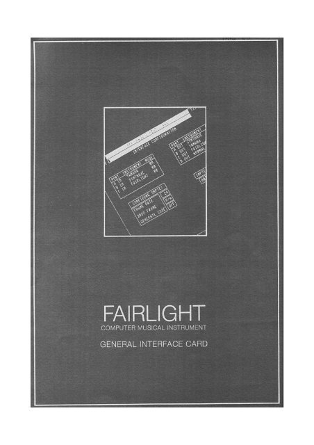
F A I R L I G H T<br />
- C M I -<br />
MANUAL FOR THE GENERAL INTERFACE<br />
(<strong>MIDI</strong>/SMPTE) CARD AND SUPPORT UNIT<br />
Revision 1.2<br />
March 1985<br />
by Tom Stewart and Peter Farleigh<br />
Description of General Interface Card........................................1<br />
Description of <strong>MIDI</strong> standards ...............................................1<br />
Description of SMPTE standards ..............................................1<br />
Fairlight <strong>MIDI</strong> ..............................................................2<br />
PAGE I description ..........................................................3<br />
SHEET 1 - TIME CODE GENERATOR ...........................................4<br />
- TIME CODE READER ..............................................5<br />
SHEET 2 - <strong>MIDI</strong> PORT CONFIGURATION .......................................6<br />
SHEET 3 - CONTROL/SWITCH CONFIGURATION ..................................7<br />
Connection Diagram ..........................................................8<br />
(c) 1985 Fairlight Instruments Pty. Ltd.<br />
Sydney, Australia<br />
General Interface Card<br />
JBE<br />
Version 05/01/99<br />
2
The General Interface Card<br />
A SMPTE/<strong>MIDI</strong>/SYNC hardware option is now available for the Computer Musical<br />
Instrument. This is in the form of a circuit card which can be insertod into one<br />
of the spare expansion slots in the CMI. The card contains its own 32-bit 68000<br />
processor, memory and peripheral interfaces providing SMPTE in and out, four<br />
independent <strong>MIDI</strong> ports in and four out, plus a gen•ral purpose SYNC pulse input<br />
and output for interfacing to non-<strong>MIDI</strong> sequencers and drum machines etc.<br />
Synchronizing with SMPTE - the industry standard<br />
The Fairlight CMI can now be programmed by the user to play sequences of music<br />
or produce sound effects triggered by SMPTE time code. SMPTE code can be<br />
produced and read by the CMI.<br />
SMPTE time code is an internationally recognized digital code recorded on a<br />
spare sound track of a multi-track tape. The code carries timing information in<br />
hours, minutes seconds and frames. By recording SMPTE time code from the<br />
beginning to the end of the audio tape, it is possible to uniquely identify any<br />
place on tape by its time code at that point.<br />
Time code 00:00:00:00 would be the beginning of time code.<br />
Time code 01:28:45:19 would be 1 hour, 28 ainutes, 45 seconds and 19<br />
frames from the beginning.<br />
A frane is a subdivision of a second that is used in film and video and can be<br />
one of the following values:<br />
for film and cinema<br />
for video (not U.S.A.)<br />
for video<br />
- 24 frames per second<br />
- 25 frames per second<br />
- 30 frames per second<br />
The Fairlight SMPTE system features include 24, 25 or 30 frames per second,<br />
"drop frame" capability for 30 fps and balanced line input and output. Signals<br />
conform to international standards.<br />
<strong>MIDI</strong> - Musical Instrument Digital Interface<br />
<strong>MIDI</strong> is the industry standard Digital keyboard interface that provides musical<br />
performance information in a standardised format which is compatible with a wide<br />
range of modern synthesizers, sequencers, drum machines, and keyboard (and<br />
other) controllers.<br />
FairlightŽs <strong>MIDI</strong> controller has three independent <strong>MIDI</strong> inputs and four<br />
independent <strong>MIDI</strong> outputs. A powerful 32-bit processor provides the fastest<br />
possible speed throughout while allowing independent data configurations to be<br />
selected for different manufacturers instruments which may be used<br />
simultaneously.<br />
Software is included on CMI system disk and is usad whenever the system is<br />
started with the General Interface card (CMI-28) pluggod in. <strong>MIDI</strong> is therefore<br />
active all the time.<br />
General Interface Card<br />
JBE<br />
Version 05/01/99<br />
3
The following information is subject to change - please check with your dealer<br />
when ordering to confirm latest specifications.<br />
Fairlight Receivinq <strong>MIDI</strong> Data<br />
Fairlight CMI will respond to the following messages received via <strong>MIDI</strong> IN.<br />
Voice messages:<br />
Note Off event<br />
Note On event<br />
Polyphonic key pressure<br />
Control change<br />
Channel pressure<br />
Pitch bend change<br />
Any Fairlight effect on Page 7 may be patched to any CONTROL (or SWITCH)<br />
and thus be controlled by any other synthesizer via <strong>MIDI</strong>.<br />
Mode messages:<br />
All Channel Mode messages are accepted but ignored. The Fairlight operates<br />
in <strong>MIDI</strong> Mode 4. Within the Fairlight, keytoards can be assigned to any<br />
combination of REGISTERS/VOICES/CHANNELS.<br />
Fairlight Transmitting <strong>MIDI</strong> Data<br />
Fairlight transmits the following data via <strong>MIDI</strong> OUT.<br />
Voice Messages:<br />
Note Off<br />
Note On<br />
Polyphonic key pressure<br />
Control change<br />
Channel pressure<br />
Pitch Bend change<br />
General Interface Card<br />
JBE<br />
Version 05/01/99<br />
4
Page I - General Interface Page<br />
This page operates in conjunction with an optional hardware circult card, the<br />
General Interface Card (or SMPTE/<strong>MIDI</strong> card). It is inserted into slot 2 in the<br />
CMI and wired to a junction box attached to the rear of the CMI (or as a remote<br />
box). See diagram for external connection.<br />
The CMI may be rapidly configured as a <strong>MIDI</strong> instrument, in a variety of transit<br />
and receive modes.<br />
Software is included on the CMI system disk (revision 14) and is used whenever<br />
the General Interface card (CMI-28) is plugged in. <strong>MIDI</strong> is therefore active all<br />
the time.<br />
The General Interface card has three input ports, A to C and four output ports,<br />
A to D. At present, only input A is supportod by software.<br />
The <strong>MIDI</strong> standard uses sixteen channels to send or receive music information.<br />
Switch and control fader information is also sent or received.<br />
Present <strong>MIDI</strong> features of Page I allow the patching of any <strong>MIDI</strong> port/channel to<br />
any of the eight Fairlight keytoards for input and output. As well, <strong>MIDI</strong><br />
switches/control fader s may be patched to Fairlight controls/switches for input<br />
and output.<br />
PAGE I has a four sheets.<br />
Select sheets by typing the sheet number; 1, 2, 3 or 4 followed by .<br />
Alternatively, sheets can be selected by pointing the light-pen at the sheet<br />
selection box in the bottom left hand corner of the scrcen. The CMI will<br />
remember what shect you are worRing on at present and returning to Page I from<br />
another page will land you on the sheet that you last used.<br />
General Interface Card<br />
JBE<br />
Version 05/01/99<br />
5
SHEET 1 - SMPTE TIME CODE CONFIGURATION<br />
This shect is divided into Time Code Generating and Time Code Reading. PAGE I<br />
can read or generate SMPTE code in different modes. These modes are described<br />
below.<br />
TIME CODE GENERATOR<br />
Record time code onto high quality multi-track tape at levels between lOdb to -<br />
20db. This will minimise bleed-through to adjacent tracks. Avoid recording onto<br />
outside tracks (e.g., track 1 or track 24 on 24 track tape) as these are the<br />
first tracks to fray as the tape is extensively used. Also avoid recording<br />
instruments with heavy percussive bass content (e.g., bass drum) on an adjacent<br />
track as this may modulate the SMPTE track.<br />
To generate time code for recording onto tape, firstly set up the START time by<br />
tabbing down to the numbers opposite START.<br />
These numbers are: hr(hour), en(minute), sc(second), fr(frame)<br />
Set the START time by typing number.<br />
Time code can now be generatod by either typing S or pointing the<br />
lightpen at the START box.<br />
To stop the time code generator, either type S or point the lightpen at<br />
the STOP box.<br />
Note that all time code readers need a few seconds to lock onto the time code,<br />
so make START time slightly early.<br />
EXAMPLE<br />
Record time code onto tape with a START time of 23 hours 59 minutes<br />
55 seconds 00 frames. This will allow sufficient time to trigger a<br />
sequence of music at SMPTE time 00 OO O0 O0.<br />
The CLOCK area above the START area will display the SMPTE code as it is<br />
generated. Similarly the CLOCK in the Time Code reader section will display the<br />
code as it is read in.<br />
FRAMB RATE can be set to 24, 25 or 30 frames per second for either generating or<br />
reading time code. When generating code at 30 fps, there is a Drop Frame option.<br />
This is used mainly with NTSC colour television applications.<br />
User bits can be used to name a tape or section of tape. User bits are set and<br />
remain constant during the generating of a section of code. They may be changed<br />
when the time code generator is stopped.<br />
General Interface Card<br />
JBE<br />
Version 05/01/99<br />
6
SHEET 1 - SMPTE TIME CODE CONFIGURATION (continued)<br />
TIME CODE READER<br />
The CMI SMPTE time code reader needs a minimum level of around 1 volt p-p.<br />
TRIGGER time is the point where music sequences may be startod. It is set up in<br />
a similar way to START TIME, described previously.<br />
The CMI has three sequencers, PAGE 9 - Keyboard Sequencer, PAGE C Music<br />
Composition Language and PAGE R - Real Time Composer. These sequencers may be<br />
triggered to start at a particular SMPTE time code. Source of the time code may<br />
be from tape, another SMPTE generator, or indeed from the CMI SMPTE time code<br />
generator.<br />
At present these sequencers will not lock with SMPTE on tape so that any<br />
variations in tape speed will not be reflected in the speed of Page 9, C or R.<br />
If this is a problem, record a ~y~__one on another track of the tape so that any<br />
tape speed variations can be taken into account.<br />
Set up your SMPTE/SYNC equipment as shown in the connection diagram.<br />
Using the time code reader with PAGE R:<br />
You can set the trigger time either on Page I or on PAGE R itself. In this<br />
release of software, there is no error checking software and hence invalid times<br />
can be loaded (e.g., loading 29 frames when reading 25 fps time code). So for<br />
the moment, take care in setting the trigger on PAGE R. PAGE R can be set to its<br />
own internal sync or to an external sync.<br />
To have PAGE R start from the trigger point type P;S.<br />
PAGE R will go into a wait state (similar to the P;W option) until the clock<br />
time reaches the trigger time.<br />
P;S .<br />
This can be over-ridden by pressing any key. This will start the sequencer.<br />
Once the sequence has startod, PAGE R will update time code as each new pattern<br />
is displayed on the screen.<br />
Using the time code reader with PAGE 9 and PAGE C:<br />
These sequencers will start at the TRIGGER time shown on Page I. At present,<br />
there are no time code indicators.<br />
General Interface Card<br />
JBE<br />
Version 05/01/99<br />
7
SHEET 2 - <strong>MIDI</strong> PORT CONFIGURATION<br />
The upper two boxes on SHEET 2 enable you to use the thrce input and four output<br />
ports with different manufacturers' <strong>MIDI</strong> equipment. This initial software<br />
release provides four different protocols: FAIRLIGHT, YAMAHA, SYNTHAXE and<br />
NORMAL, (the 'standard' <strong>MIDI</strong> protocol). More will be available shortly.<br />
To setup the <strong>MIDI</strong> ports, firstly connoct the <strong>MIDI</strong> equipment to the appropriate<br />
<strong>MIDI</strong> input/output port on the <strong>MIDI</strong>/SMPTE junction box at the rear of the CMI.<br />
Secondly, on SHEET 2, tab to the INSTRUMENT field opposite the appropriate port<br />
and type the manufacturers name followed by . Just the first letter will<br />
suffice, for example, Y.<br />
The MODE field enables you to specify options to the manufacturers' equipment in<br />
which the <strong>MIDI</strong> port is to operate.<br />
A hexadecimal code number is assigned to the appropriate field to select special<br />
modes. At present this is only available for the Synthaxe as follows;<br />
With the low digit<br />
no. 1 (see below);<br />
if it is<br />
With the high digit<br />
if it is<br />
= 0, the Synthaxe vibrato arm affects control<br />
= 1, the vibrato arm does pitch bend.<br />
= 0, all strings damp together;<br />
= 1, independent string damping.<br />
Here's a typical setup ...<br />
SHEET 2 - <strong>MIDI</strong> channels/FAIRLIGHT KEYBOARDS<br />
This sLect is usad to map <strong>MIDI</strong> channels to FAIRLIGHT keyLoard for input ports,<br />
and vice versa for output ports. To do this patching, move cursor to the fields<br />
relating to the FAIRLIGHT keytoard in question, and assign both port code, A, B,<br />
C or D, and <strong>MIDI</strong> channel number, 1 to 16.<br />
For example ...<br />
General Interface Card<br />
JBE<br />
Version 05/01/99<br />
8
SHEET 3 - <strong>MIDI</strong>/FAIRLIGHT CONTROL/SWITCH NUMBER CONFIGURATION<br />
Fairlight control/switch numbers are split into groups of eight, as seen in the<br />
patching boxes. To patch, assign a port and channel to the relevant CN/SW<br />
numbers.<br />
For output ports, each bank of eight FAIRLIGHT Control/Switch numbers can be<br />
mapped to <strong>MIDI</strong> CN/SW numbers 0-7 via the selectod port and channel. Current<br />
software allows <strong>MIDI</strong> CN/SW numbers no greater than 7 on output channels.<br />
For input ports, patching is the same, but <strong>MIDI</strong> Control/Switch numbers greater<br />
than 7 are avaliable. Numbers outside the range are mapped on a rotating basis<br />
to the selected bank of FAIRLIGHT Control/Switch numbers, via port and channel<br />
combinations which you have selected.<br />
For example, if you mapped input port A, channel 5 to FAIRLIGHT Control/Switch<br />
numbers in the group 09 - 16 then any <strong>MIDI</strong> CN/SW number information arriving via<br />
"A/5" will be mapped thus: <strong>MIDI</strong> 0,8,16,24 - FAIRLIGHT 1 (Control/Switch numbers<br />
1 to 8); <strong>MIDI</strong> 1,9,17,25 - FAIRLIGHT 2 (Control/Switch numbers 9 to 16), and so<br />
on<br />
NOTE: If it is desired to prevent this four to one cyclic mapping from occuring,<br />
the sending <strong>MIDI</strong> device must ensure that it "routes" each bank of eight<br />
Control/Switch numbers via a different port/channel.<br />
A typical control/switch allocation ...<br />
General Interface Card<br />
JBE<br />
Version 05/01/99<br />
9
GENERAL INTERFACE SUPPORT UNIT - CONNECTION<br />
General Interface Card<br />
JBE<br />
Version 05/01/99<br />
10


