KIMO CP100 Data Sheet - Envirolab
KIMO CP100 Data Sheet - Envirolab
KIMO CP100 Data Sheet - Envirolab

You also want an ePaper? Increase the reach of your titles
YUMPU automatically turns print PDFs into web optimized ePapers that Google loves.
Technical <strong>Data</strong> <strong>Sheet</strong><br />
Pressure • Temperature • Humidity • Air Velocity • Airflow • Sound level<br />
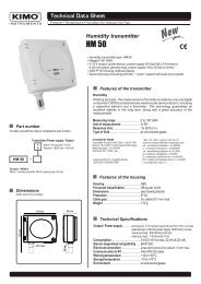
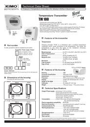
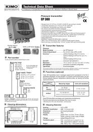
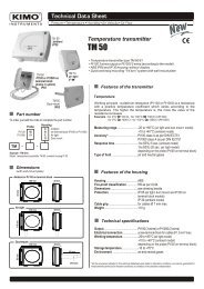
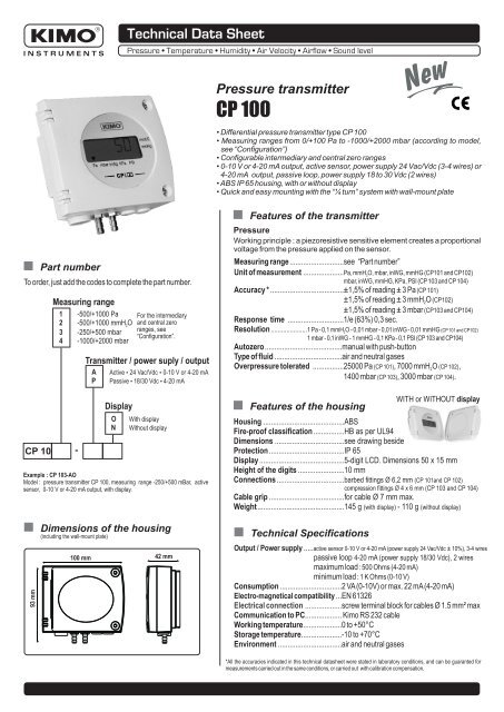
Pressure transmitter<br />
CP 100<br />
New<br />
New<br />
• Differential pressure transmitter type CP 100<br />
• Measuring ranges from 0/+100 Pa to -1000/+2000 mbar (according to model,<br />
see “Configuration”)<br />
• Configurable intermediary and central zero ranges<br />
• 0-10 V or 4-20 mA output, active sensor, power supply 24 Vac/Vdc (3-4 wires) or<br />
4-20 mA output, passive loop, power supply 18 to 30 Vdc (2 wires)<br />
• ABS IP 65 housing, with or without display<br />
• Quick and easy mounting with the “¼ turn” system with wall-mount plate<br />
93 mm<br />
Part number<br />
To order, just add the codes to complete the part number.<br />
CP 10<br />
Measuring range<br />
1 -500/+1000 Pa<br />
2 -500/+1000 mmH 2<br />
O<br />
3 -250/+500 mbar<br />
4 -1000/+2000 mbar<br />
-<br />
Dimensions of the housing<br />
(including the wall-mount plate)<br />
100 mm<br />
Transmitter / power suply / output<br />
A<br />
P<br />
Active • 24 Vac/Vdc • 0-10 V or 4-20 mA<br />
Passive • 18/30 Vdc • 4-20 mA<br />
Display<br />
O<br />
N<br />
For the intermediary<br />
and central zero<br />
ranges, see<br />
“Configuration”.<br />
With display<br />
Without display<br />
Example : CP 103-AO<br />
Model : pressure transmitter CP 100, measuring range -250/+500 mBar, active<br />
sensor, 0-10 V or 4-20 mA output, with display.<br />
42 mm<br />
Features of the transmitter<br />
Pressure<br />
Working principle : a piezoresistive sensitive element creates a proportional<br />
voltage from the pressure applied on the sensor.<br />
Measuring range............................see “Part number”<br />
Unit of measurement .....................Pa, mmH2O, mbar, inWG, mmHG (CP101 and CP102)<br />
mbar, inWG, mmHG, KPa, PSI (CP 103 and CP 104)<br />
Accuracy * ......................................±1,5% of reading ± 3 Pa (CP 101)<br />
±1,5% of reading ± 3 mmH O (CP102)<br />
2<br />
±1,5% of reading ± 3 mbar (CP103 and CP104)<br />
Response time .............................1/e (63%) 0,3 sec.<br />
Resolution .....................1 Pa - 0,1 mmH2O - 0,01 mbar - 0,01 inWG - 0,01 mmHG (CP 101 and CP102)<br />
1 mbar - 0,1 inWG - 1 mmHG - 0,1 KPa - 0,1 PSI (CP 103 and CP104)<br />
Autozero........................................manual with push-button<br />
Type of fluid ...................................air and neutral gases<br />
Overpressure tolerated ................25000 Pa (CP 101), 7000 mmH O (CP 102),<br />
2<br />
1400 mbar (CP 103), 3000 mbar (CP 104).<br />
Features of the housing<br />
WITH or WITHOUT display<br />
Housing ..........................................ABS<br />
Fire-proof classification ................HB as per UL94<br />
Dimensions ....................................see drawing beside<br />
Protection .......................................IP 65<br />
Display ............................................5-digit LCD. Dimensions 50 x 15 mm<br />
Height of the digits ........................10 mm<br />
Connections ...................................barbed fittings Ø 6,2 mm (CP 101and CP 102)<br />
compression fittings Ø 4 x 6 mm (CP 103 and CP 104)<br />
Cable grip .......................................for cable Ø 7 mm max.<br />
Weight.............................................145 g (with display) - 110 g (without display)<br />
Technical Specifications<br />
Output / Power supply .....active sensor 0-10 V or 4-20 mA (power supply 24 Vac/Vdc ± 10%), 3-4 wires<br />
......................................... passive loop 4-20 mA (power supply 18/30 Vdc), 2 wires<br />
......................................... maximum load : 500 Ohms (4-20 mA)<br />
......................................... minimum load : 1 K Ohms (0-10 V)<br />
Consumption ................................2 VA (0-10V) or max. 22 mA (4-20 mA)<br />
Electro-magnetical compatibility ...EN 61326<br />
Electrical connection ................... screw terminal block for cables Ø 1.5 mm² max<br />
Communication to PC................... Kimo RS 232 cable<br />
Working temperature....................0 to +50°C<br />
Storage temperature.....................-10 to +70°C<br />
Environment .................................air and neutral gases<br />
*All the accuracies indicated in this technical datasheet were stated in laboratory conditions, and can be guaranted for<br />
measurements carried out in the same conditions, or carried out with calibration compensation.
Connection<br />
For the models<br />
101<br />
101<br />
CP 102 - AO and CP 102 - AN • output 0-10 V or 4-20 mA - active<br />
103<br />
103<br />
104<br />
104<br />
e<br />
Connection to PC<br />
via LCC 100 software<br />
d<br />
DIP switch<br />
OR<br />
a<br />
a<br />
Output 0-10 V<br />
GND ......ground<br />
Vdc P.....direct voltage (pressure)<br />
Output 4-20 mA<br />
Idc P ......direct current (pressure)<br />
GND ......ground<br />
Autozero<br />
a<br />
Output<br />
terminal block<br />
OR<br />
b<br />
b<br />
Direct power supply<br />
Vdc ......direct voltage<br />
GND ....ground<br />
Alternative power supply<br />
Vac.......alternative voltage (phase)<br />
Vac.......alternative voltage (neutral)<br />
Pressure<br />
connection<br />
(compression fittings shown)<br />
c<br />
Cable grip<br />
b<br />
Power supply<br />
terminal block<br />
For the models<br />
101<br />
101<br />
CP 102 - PO and CP 102 - PN • Output 4-20 mA - passive<br />
103<br />
103<br />
104<br />
104<br />
a<br />
Terminal block<br />
c<br />
Cable grip : to insert the cable, it is required to slightly cut the rubber.<br />
a<br />
Vdc ......direct voltage<br />
IP..........direct current (pressure)<br />
!<br />
Electrical connections - as per norm NFC15-100<br />
This connection must be made by a qualified technician. To make the connection, the transmitter must not be energized.<br />
For the models<br />
101<br />
101<br />
CP 102 - AO and CP 102 - and • output 0-10 V or 4-20 mA - active<br />
103<br />
103<br />
104<br />
104<br />
Output 4-20 mA<br />
Output<br />
terminal<br />
block<br />
Idc P<br />
GND<br />
Vdc P<br />
Vdc<br />
Power supply<br />
terminal block<br />
GND<br />
!<br />
+<br />
-<br />
+<br />
+<br />
-<br />
4 wires<br />
-<br />
+<br />
Power supply<br />
24 Vdc<br />
or<br />
Vac<br />
Vac<br />
~<br />
~<br />
+<br />
-<br />
Regulator display<br />
or PLC/BMS<br />
passive<br />
~ ~<br />
or<br />
Power supply<br />
24 Vac<br />
Classe II<br />
-<br />
+<br />
Output 0-10 V<br />
Regulator display<br />
or PLC/BMS<br />
passive<br />
4 wires<br />
3 wires<br />
To make a 3-wire connection, before powering up the transmitter, please connect the<br />
output ground to the input ground. See drawing below.<br />
For the models<br />
101<br />
101<br />
CP 102 - PO and CP 102 - PN • output 4-20 mA - passive<br />
103<br />
103<br />
104<br />
104<br />
Vdc<br />
IP<br />
+<br />
-<br />
2 wires<br />
Power supply<br />
18-30 Vcc<br />
+<br />
or<br />
-<br />
-<br />
+<br />
2 wires<br />
Regulator display<br />
or PLC /BMS<br />
passive type<br />
Output<br />
terminal block<br />
Power supply<br />
terminal block<br />
+<br />
+<br />
Idc P +<br />
Idc P +<br />
- Output<br />
Output<br />
GND<br />
4-20 mA<br />
- 4-20 mA<br />
-<br />
Output GND<br />
or<br />
- or<br />
terminal block<br />
+ 0-10 V<br />
0-10 V<br />
+<br />
Vdc P +<br />
Vdc P +<br />
Vdc<br />
GND<br />
+<br />
3 wires 3 wires<br />
Vac<br />
Power supply ~<br />
or terminal block<br />
GND<br />
+ -<br />
Phase Neutral<br />
Power supply<br />
Power supply<br />
24 Vdc<br />
24 Vac<br />
Vdc<br />
IP<br />
+<br />
-<br />
2 wires<br />
+<br />
I in<br />
Regulator display<br />
or PLC/BMS<br />
active type<br />
2
Autozero<br />
To make an autozero, please disconnect the 2 pressure connections and briefly press on the push-button.<br />
Configuration<br />
It is possible to configure the measuring ranges, the units, the output of the instrument (according to<br />
the model) either by switch and/or via software (connections e and d on drawing “connection”).<br />
Configuration by the DIP switch<br />
To configure the instrument, please unscrew the 2 screws from the housing, and then<br />
open it.<br />
Identification of the DIP switches<br />
on the electronic board<br />
Electronic<br />
board<br />
Output Units setting<br />
d<br />
DIP switch<br />
}<br />
To configure the transmitter, it must not be<br />
energized. Then, you can make the settings<br />
required, with the DIP switches (as shown on<br />
the drawing beside). When the transmitter is<br />
configured, you can power it up.<br />
1 2 3 4<br />
DIP switch 1<br />
1<br />
2<br />
On-off switch 3<br />
4<br />
DIP switch 2<br />
}<br />
Measuring<br />
range<br />
setting<br />
Standard range<br />
or central 0 setting<br />
! Caution !<br />
Please follow carefully the combinations beside<br />
with the DIP switch.<br />
If the combination is wrongly done, the following<br />
message will appear on the display of the transmitter<br />
“CONF ERROR”.<br />
In that case, you will have to unplug the transmitter,<br />
place the DIP switches correctly, and then power the<br />
transmitter up.<br />
• Output setting DIP switch 1<br />
Configurations 4-20 mA 0-10 V<br />
To set the type of analogic output, please put<br />
the on-off switch of the output as shown beside.<br />
• Units setting<br />
DIP switch 1<br />
(For models CP 101 - AO and CP 101 - AN )<br />
102<br />
102<br />
103<br />
103<br />
104<br />
104<br />
Combinations<br />
Configurations Pa mmH2O mbar inWG mmHG<br />
1 2 3 4 1 2 3 4<br />
KPa<br />
PSI<br />
To set the measuring unit, put the<br />
on-off switches 2, 3 and 4 of units<br />
as shown beside.<br />
Combinations<br />
CP101 and CP 102<br />
CP103 and CP 104<br />
1 2 3 4 1 2 3 4 1 2 3 4 1 2 3 4 1 2 3 4<br />
1 2 3 4 1 2 3 4<br />
x x x x x<br />
x x x x x<br />
• Measuring range setting<br />
DIP switch 2<br />
To set the measuring range, put the on-off<br />
switches 1, 2 and 3 of the measuring range as<br />
shown beside.<br />
Example :<br />
0 ----> +750 mmH2O, the measuring range is 750 mmH2O<br />
-500 Pa ----> +500 Pa,the measuring range is 1000 Pa<br />
To configure other intermediary ranges, and for an easier<br />
and more friendly configuration, please refer to<br />
"Configuration via software".<br />
Combinations<br />
CP 101<br />
CP 102<br />
CP 103<br />
CP 104<br />
1<br />
2<br />
3<br />
4<br />
1<br />
2<br />
3<br />
4<br />
Pa 100 250 500 750 1000<br />
mmH2O 10,0 25,0 50,0 75,0 100,0<br />
mbar 1,00 2,50 5,00 7,50 10,00<br />
inWG 0,40 1,00 2,00 3,00 4,00<br />
mmHG 0,80 2,00 4,00 6,00 8,00<br />
mmH2O 100,0 250,0 500,0 750,0 1000,0<br />
Pa 1000 2500 5000 7500 10000<br />
mbar 10,00 25,00 50,00 75,00 100,00<br />
inWG 4,00 10,00 20,00 30,00 40,00<br />
mmHG 8,00 20,00 40,00 60,00 80,00<br />
mbar 100 200 300 400 500<br />
inWG 40,0 80,0 120,0 160,0 200,0<br />
Kpa 10,0 20,0 30,0 40,0 50,0<br />
PSI 2,0 4,0 6,0 8,0 10,0<br />
mmHG 80 160 240 320 400<br />
mbar 500 750 1000 1500 2000<br />
inWG 200,0 300,0 400,0 600,0 800,0<br />
Kpa 50,0 75,0 100,0 150,0 200,0<br />
PSI 10,0 15,0 20,0 30,0 40,0<br />
mmHG 400 600 800 1200 1600<br />
1<br />
2<br />
3<br />
4<br />
1<br />
2<br />
3<br />
4<br />
1<br />
2<br />
3<br />
4<br />
• Standard range / central zero setting DIP switch 2<br />
To set the type of range, put the on-off switch 4 as shown beside :<br />
Example : standard / 0<br />
(0 / 100 Pa)<br />
central zero<br />
(-50 Pa / 0 / +50 Pa)<br />
Configurations<br />
Combinations<br />
Full scale<br />
1<br />
2<br />
3<br />
4<br />
central zero<br />
1<br />
2<br />
3<br />
4<br />
3
Initialization of the transmitter<br />
When the transmitter is powered up, it initializes and displays the digits 0.0.0.0.0 , and then its configuration including :<br />
- the measuring range - the analog output.<br />
1- The measuring range<br />
The following message is displayed : L . This is the low value of the measuring range, and its digit value : ex : - 500 . . .<br />
The following message is displayed : H. . This is the high value of the measuring range and its digit value : ex : - 500 . .<br />
The arrow displayed (at the bottom or on the right of the screen) is relative to the unit of measurement : ex : from -500 to +500 Pa.<br />
2 - The analog output<br />
If the analog output is in 4-20 mA, then the following message will appear 4-20A . . . . .<br />
If the analog output is 0-10 V, then the following message will appear 0. -.0.<br />
0 .<br />
After the display of the configuration, the transmitter displays<br />
, which confirms that the initialization is finished and you can start the measurements.<br />
Configuration via software<br />
(with optional LCC 100 software)<br />
An easy and friendly configuration with the software !<br />
You can configure your own intermediary ranges.<br />
! Caution !<br />
For a pressure transmitter, the minimum configurable range is 10% of the full positive range.<br />
Example : for a transmitter with a range of -500 / +1000 Pa, the minimum configurable range is 100 Pa.<br />
For example, you can configure your transmitter with a range of -20 to +80 Pa, from 0 to +600 Pa,<br />
or from -450 to +450 Pa...<br />
• To access the configuration via software :<br />
- Set the DIP switches as shown beside. Nota : the on-off switch 1 of the DIP switch 1 can be in<br />
any position (selection of the analogic output 0-10 V or 4-20 mA).<br />
- Connect the cable to the transmitter plug (see “connections”).<br />
• Please refer to the user manual of the LCC 100 to make the configuration.<br />
! Caution !<br />
The configuration of the parameters can be done either with the DIP switch or via software (you<br />
cannot combine both solutions)<br />
Mounting<br />
Installation : mount the ABS plate on the wall (this plate is supplied with the<br />
transmitter). Drilling : Ø 6 mm (with the screws and pins supplied with the<br />
transmitter). Insert the transmitter on the plate (see A on the drawing beside)<br />
and rotate its housing in clockwise direction until you hear a “click", which<br />
confirms that the transmitter is correctly installed.<br />
! Caution !<br />
Once the transmitter is installed and<br />
powered up, please make an autozero to<br />
guarantee the correct working of the<br />
transmitter in any position.<br />
Maintenance<br />
Please avoid any aggressive solvent.<br />
Please protect the transmitter and its probes from any cleaning product<br />
containing formol, that may be used for cleaning roots or ducts<br />
Options<br />
Power supply class 2, input 230 Vac,<br />
output 24 Vac, ref.KIAL-100A<br />
Configuration software LCC 100 supplied<br />
with connection RS 232 cable<br />
ABS<br />
plate<br />
Accessories<br />
Connection tube<br />
Connection fittings<br />
Through-connections<br />
Straight connections<br />
Spherical coupling nut<br />
Any position<br />
(no specific position<br />
required)<br />
A<br />
73 mm<br />
40 mm<br />
7 mm<br />
1 2 3 4<br />
DIP switch 1<br />
1<br />
2<br />
3<br />
4<br />
A<br />
Ø 8 mm<br />
Ø 4,5 mm<br />
DIP switch 2<br />
50 mm<br />
68 mm<br />
Ref. FT ang - CP 100 - 10/06 B - We reserve the right to modify the characteristics of our products without notice.<br />
www.kimo.fr Distributed by :<br />
EXPORT DEPARTMENT<br />
Tel : + 33. 1. 60. 06. 69. 25 - Fax : + 33. 1. 60. 06. 69. 29<br />
e-mail : export@kimo.fr