KIMO TST Data Sheet - Envirolab
KIMO TST Data Sheet - Envirolab
KIMO TST Data Sheet - Envirolab

Create successful ePaper yourself
Turn your PDF publications into a flip-book with our unique Google optimized e-Paper software.
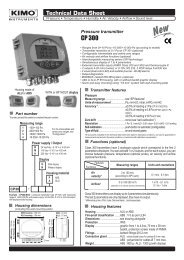
Technical <strong>Data</strong> <strong>Sheet</strong><br />
Pressure • Temperature • Humidity • Air Velocity • Airflow • Sound level<br />
Thermostats<br />
<strong>TST</strong><br />
New<br />
New<br />
<strong>TST</strong><br />
air tight IP 65<br />
<strong>TST</strong><br />
ambient<br />
IP 30<br />
<strong>TST</strong><br />
Pt100 on<br />
terminal block<br />
(probe in option)<br />
IP 65<br />
• Measuring ranges from 0 to +50°C, -20 to +80°C, -100 to +400°C<br />
• RCR relay output 3A/230Vac. Power supply 24Vac/Vdc<br />
• Visual alarm, red LED in front<br />
• ABS IP 65 and IP 30 housing, with display<br />
• Quick and easy mounting with the “¼ turn” system with wall-mount plate<br />
Features of the transmitter<br />
Temperature<br />
A Pt100 is a resistance with a positive temperature coefficient which<br />
varies according to the temperature. The higher the temperature is, the<br />
more the value of the resistance increases.<br />
Example : for 0°C 100 - for100°C 138,5<br />
To order, just add the code to complete the part number :<br />
110 mm<br />
110 mm<br />
83 mm<br />
Part number<br />
<strong>TST</strong> -<br />
Ambient<br />
Air tight<br />
100 mm<br />
100 mm<br />
Ø13 mm<br />
Pt 100 input on terminal block<br />
100 mm<br />
Probe<br />
M Ambient<br />
E Air tight<br />
B Pt100 input, on terminal block<br />
Example : <strong>TST</strong>-B corresponds to a <strong>TST</strong> thermostat with Pt 100 input on<br />
terminal block (probe in option).<br />
30 mm<br />
42 mm<br />
42 mm<br />
42 mm<br />
Ø13 mm<br />
Measuring ranges.................................0 to +50°C (ambient model)<br />
-20 to +80°C (air tight model)<br />
according to the probe : -100 to +400°C<br />
(Pt100 input on terminal block)<br />
Unit of measurement .........................°C, °F<br />
Accuracy * ..........................................±1% of reading ±0,4°C<br />
Operating time....................................1/e (63%) 5 sec. (ambient model)<br />
1/e (63%) 20 sec. (air tight model)<br />
according to probe (Pt100 input on terminal block)<br />
Resolution ..........................................0,1°C<br />
Type of transmitter.............................Pt 100 class A as per DIN IEC 751<br />
Type of fluid........................................air and neutral gases<br />
Features of the housing<br />
Housing...............................................ABS<br />
Fire-proof classification ....................HB as per UL94<br />
Dimensions.........................................see drawing beside<br />
Protection ...........................................IP30 (ambient model)<br />
IP65 (air tight and Pt100 on terminal block models)<br />
Display ................................................5-digit LCD. Dimensions 50 x 15 mm<br />
Height of the digits ............................10 mm<br />
Cable grip ...........................................for cables Ø 7 mm max.<br />
Weight .................................................145 g<br />
Technical specifications<br />
Output .................................................1 RCR relay 3A/230 Vac<br />
Relay and alarm status .......................red LED in front<br />
Set point .............................................1 configurable set point<br />
Power supply ......................................24 Vac/Vdc ±10%<br />
Consumption......................................2 VA<br />
Electromagnetical compatibility .......EN 61326<br />
Electrical connection ........................ screw terminal block for cable Ø 1.5 mm² max.<br />
Communication to PC ........................ Kimo RS 232 cable<br />
Working temperature ........................+10 to +40°C (ambient model)<br />
.............................................................-10 to +50°C (air tight model)<br />
............................................................. according to probe (Pt100 input on terminal block)<br />
Storage temperature ..........................-10 to +70°C<br />
Environment .......................................air and neutral gases<br />
*All the accuracies indicated in this technical datasheet were stated in laboratory conditions, and can be guaranted for<br />
measurements carried out in the same conditions, or carried out with calibration compensation.
Connection<br />
For models<br />
<strong>TST</strong>-M and <strong>TST</strong>-E<br />
f<br />
Set point<br />
configuration button<br />
d<br />
DIP switch<br />
a<br />
Relay<br />
NC..................Normally closed<br />
COM ..............Common<br />
NO .................Normally open<br />
e<br />
Connection to PC via<br />
LCC 100 software<br />
b<br />
Power supply<br />
Vdc .........direct voltage<br />
GND .......ground<br />
or<br />
c<br />
Cable grip<br />
b<br />
a<br />
Relay<br />
terminal<br />
block<br />
Power supply<br />
terminal block<br />
b<br />
Vac .........alternative voltage (phase)<br />
Vac .........alternative voltage (neutral)<br />
For model<br />
<strong>TST</strong>-B<br />
Pt100<br />
d<br />
terminal<br />
block<br />
2’ 2 1<br />
c<br />
Cable grip : to insert the cable, it is required to slightly cut the rubber.<br />
!<br />
Electrical connections - as per norm NFC15-100<br />
This connection must be made by a qualified technician. To make the connection, the transmitter must not be energized.<br />
For models<br />
<strong>TST</strong>-M and <strong>TST</strong>-E<br />
Relay terminal block COM<br />
Power supply terminal block<br />
NC<br />
NO<br />
Vdc<br />
GND<br />
+<br />
-<br />
-<br />
+<br />
Power supply<br />
24 Vdc<br />
or<br />
or<br />
Vac<br />
Vac<br />
Vac<br />
Vac<br />
~<br />
~ ~ ~<br />
Power supply<br />
24 Vac<br />
Class II<br />
Neutral Phase<br />
Power supply<br />
24 Vac<br />
Connection of the Pt100 probe<br />
For model<br />
<strong>TST</strong>-B<br />
2'<br />
2<br />
1<br />
Pt100<br />
Configuration<br />
Configuration of measuring units, set points, can be carried out different ways : DIP switch, push-button and/or software<br />
(connections e , f and d on drawing “connection”).<br />
Configuration of measuring units by DIP switch<br />
To configure the transmitter, please unscrew the 2 screws from the housing,<br />
and then open it.<br />
d<br />
Electronic<br />
board<br />
DIP switch<br />
Identification of the DIP switches<br />
on the electronic board<br />
1<br />
2<br />
} 3<br />
1 2 3 4<br />
4 DIP<br />
switch 2<br />
DIP<br />
switch 1 Setting of units<br />
Interrupteur<br />
Inactive<br />
To configure the transmitter, it must not be<br />
energized. Then, you can make the settings<br />
required, thanks to the DIP switches (as shown<br />
on the drawing beside). When the transmitter is<br />
configured, you can power it up.<br />
! Caution !<br />
Please follow carefully the combinations beside with the<br />
DIP switch.<br />
If the combination is wrongly done, the following message will<br />
appear on the display of the transmitter “CONF ERROR”.<br />
In that case, you will have to unplug the transmitter, replace the<br />
DIP switches correctly, and then power the transmitter up.<br />
2
• Setting of units<br />
Configurations °C °F<br />
To set the unit of measurement, please put the on-off<br />
buttons 3 and 4 of the units as shown beside.<br />
Combinations<br />
1<br />
2<br />
3<br />
4<br />
1<br />
2<br />
3<br />
4<br />
Set points configuration with the push-button<br />
Power the transmitter up : it will then display its current configuration.<br />
To modify the configuration, please proceed as follows :<br />
Remove the 2 screws from the housing and open it.<br />
The settings are done with the button located on the electronic board<br />
(see photo beside).<br />
Set point<br />
configuration<br />
button<br />
Electronic<br />
board<br />
Principle :<br />
- By pressing on this button for more than 3 seconds, you can validate the setting and go to the next setting.<br />
- By pressing quickly on this button, you can increment a value and scroll down the different options or values.<br />
This button enables :<br />
1- to activate/deactivate an alarm (set point)<br />
2- to program the action of the alarm (rising/falling/regulation action)<br />
3- to set the set point value<br />
4- to set the time-delay (temporisation)<br />
To set the different options :<br />
AL.O<br />
0000.0<br />
00.SEC<br />
AL.OFF<br />
1- Activating/deactivating the alarm :<br />
After pressing the set point configuration button for more than 3 seconds, Co CONF F. will be displayed, then AL.ON<br />
or<br />
AL.OFF (depending on the last configuration of the transmitter).<br />
Afterwards, by briefly pressing on this button, you can switch between AL.ON<br />
(alarm on) and AL.OFF (alarm off).<br />
To validate your choice, press again for 3 seconds. If you chose<br />
AL.OFF , then you will exit the configuration mode and<br />
switch back to the measurement mode. If you chose AL.OFF<br />
, you will move to the next parameter.<br />
2- Programming the action of the alarm (rising/falling/regulation action) :<br />
Rising action (1 set point) : the alarm will activate when the measure exceeds the set point and will stop when the<br />
measure goes below the set point.<br />
Falling action (1 set point) : the alarm will activate when the measure goes below the set point and will stop when the<br />
measure goes above the set point.<br />
Regulation mode (2 set points) : the set point values will determine the action type. Two possibilities are available:<br />
Measurement<br />
set point 1 > set point 2 Measurement set point 2 > set point 1<br />
set point 1<br />
set point 2<br />
Alarme set<br />
Time-delay<br />
set point 2<br />
set point 1<br />
<br />
Time<br />
<br />
Time<br />
Measure > set point 1 Alarm activation<br />
Measure < set point 2 Alarm stop<br />
set point 2Measure set point 1 No change<br />
Measure < set point 1 Alarm activation<br />
Measure > set point 2 Alarm stop<br />
set point 1Measure set point 2 No change<br />
Press the button for 3 seconds to confirm your choice. You will then move on to the last parameter.<br />
3- Programming the set point value :<br />
The set point is a limit which, when being reached and/or exceeded, activates the relay and the visual red LED alarm.<br />
The first digit will start to blink, by briefly pressing on the button, you can choose if the set point will be either positive (0) or<br />
negative (-). Then press the button during 3 seconds to confirm your choice. The second digit will start to blink. Press the<br />
button briefly to change the value. Then press the button during 3 seconds to confirm your choice. Repeat this sequence until<br />
you have reached the last digit and then confirm the set point. If you selected regulation mode , you will program the<br />
second set point.<br />
4- Setting of the time-delay (dead band temporisation 60 sec max) :<br />
When the set point is reached and/or exceeded, the time-delay will wait the specified time before energizing the relay, if the<br />
set point is still reached and/or exceeded.<br />
When the first digit starts blinking, press briefly on the button to change the value. Then press the button during 3 seconds to<br />
confirm your choice. Repeat the process until all digits have the desired value and press the button for 3 seconds to confirm<br />
your choice.<br />
The programming is now done and the display switches back to the measurement mode.<br />
3
Initialization of the transmitter<br />
When the transmitter is powered up, it initializes and displays the digits 0.0.0.0.0 , and then its configuration including :<br />
- 1 - the measuring range - 3 - action of the alarm (rising, falling or regulation action)<br />
- 2 - the status of the alarm - 4 - the set point<br />
1- The measuring range<br />
- 5 - time-delay (dead band temporisation)<br />
The following message is displayed : L . This is the low value of the measuring range, and its digit value : ex : - 500 . . .<br />
The following message is displayed : H. . This is the high value of the measuring range and its digit value : ex : 1000 . . . .<br />
The arrow displayed (at the bottom or on the right of the screen) is relative to the unit of measurement : ex : from -500 to 1000 Pa.<br />
2 - The status of the alarm<br />
When the alarm is off, the following message is displayed : al.off . . . .<br />
When the alarm is on, the following message is displayed : al.o . .<br />
• When the alarm is off, the transmitter displays , which confirms<br />
the end of initialization and that you can start the measurements .<br />
• When the alarm is on, the transmitter displays the parameters relative to<br />
the relay (set point, program of the alarm, time-delay).<br />
3 - Action of the alarm (rising or falling action)<br />
If the relay is programmed in rising action, the following message is displayed :<br />
If the relay is programmed in falling action, the following message is displayed :<br />
This message is displayed : ex : 250 . . , which means that the alarm<br />
If the relay is programmed in regulation mode, the following message is displayed .<br />
Configuration via software<br />
(with the optional LCC100 software)<br />
An easy and friendly way to configure!<br />
You can configure the measuring units, the set point, the time-delay...<br />
• To access the configuration via software, you must first position the DIP switch, as per the following picture<br />
(shown beside), and then connect the cable to the transmitter (see “connections” drawing).<br />
• Please refer to the user manual of the LCC 100 to make the configuration.<br />
! Caution !<br />
The configuration can be made either by switch, or by software (you can not combine both solutions).<br />
Mounting<br />
Installation : mount the ABS plate on the wall (this plate is supplied<br />
with the transmitter). Drilling : Ø 6 mm, with the screws and pins<br />
supplied with the transmitter. Insert the transmitter into the plate (see<br />
points A of the drawing beside), by tilting it at 30°. Rotate the housing<br />
in clockwise direction until you hear a “click” which confirms that the<br />
transmitter is correctly installed.<br />
Maintenance<br />
Please avoid any aggressive solvent.<br />
Please protect the transmitter and its probes from any cleaning product<br />
containing formol, that may be used for cleaning rooms or ducts.<br />
Options<br />
Power supply class 2, input 230 Vac, output 24 Vac, ref.KIAL-100A<br />
Configuration software LCC 100 with RS 232 cable<br />
Temperature probes Pt100 3 wires<br />
.<br />
ABS<br />
plate<br />
4- The set point (alarm on)<br />
This message is displayed : ex : 250 . . , which means that the alarm<br />
will be activated as soon as the measurement exceeds this value.<br />
If you chose regulation mode , the second set point will appear.<br />
5 - The time-delay (alarm on)<br />
This message is displayed : i.sec . . .<br />
The temporisation is in seconds (from 0 to 60 sec.).<br />
After having displayed the configuration, the transmitter displays<br />
which confirms that the nitialization is finished and you can start<br />
the measurements.<br />
A<br />
73 mm<br />
40 mm<br />
7 mm<br />
A<br />
1<br />
2<br />
3<br />
4<br />
DIP switch 1<br />
Ø 8 mm<br />
Ø 4,5 mm<br />
1 2 3 4<br />
DIP switch 2 Off<br />
50 mm<br />
68 mm<br />
Ref. FT ang - <strong>TST</strong> - 12/08 D - We reserve the right to modify the characteristics of our products without notice.<br />
,<br />
www.kimo.fr Distributed by :<br />
EXPORT DEPARTMENT<br />
Tel : + 33. 1. 60. 06. 69. 25 - Fax : + 33. 1. 60. 06. 69. 29<br />
e-mail : export@kimo.fr