Live-FSH8R Fast Ethernet Switch Product Features
Live-FSH8R Fast Ethernet Switch Product Features
Live-FSH8R Fast Ethernet Switch Product Features

Create successful ePaper yourself
Turn your PDF publications into a flip-book with our unique Google optimized e-Paper software.
<strong>Live</strong>-<strong>FSH8R</strong><br />
<strong>Fast</strong> <strong>Ethernet</strong> <strong>Switch</strong><br />
8 × 10/100Mbps<br />
NWay 10/100BASE-TX<br />
<strong>Fast</strong> <strong>Ethernet</strong> <strong>Switch</strong><br />
with Auto-MDI/MDIX<br />
User’s Manual
Trademarks<br />
All rights reserved.<br />
Air<strong>Live</strong> Logo is an registered trademarks of OvisLink Corp, Taiwan. Other product names<br />
and company names are trademarks or registered trademarks of their respective owners.<br />
FCC Warning<br />
This equipment has been tested and found to comply with the requirements for a Class A<br />
digital device, pursuant to Part 15 of the FCC Rules. These requirements are designed for<br />
reasonable protection against harmful interference when the equipment operating in a<br />
commercial environment. This equipment can generate and radiate electromagnetic energy<br />
and, if not installed and used in accordance with this guide, may cause significant<br />
interference with radio communication. Operation of this equipment in a residential area is<br />
likely to cause interference to household appliances, in which case the user will be required<br />
to amend at his or her own expense.<br />
CE Mark Warning<br />
This is a Class A product. In a domestic environment, this product may cause radio<br />
interference, in which case the user may be required to take adequate preventive measures.<br />
Disclaimer<br />
Contents in this manual are subject to changes without prior notice.<br />
About this User’s Manual<br />
This User’s Manual aims at helping users to know the key features of<br />
<strong>Live</strong>-<strong>FSH8R</strong> <strong>Fast</strong> <strong>Ethernet</strong> <strong>Switch</strong> and to install it in a 10/100BASE-TX<br />
<strong>Fast</strong> <strong>Ethernet</strong> Local Area Network (LAN).<br />
OvisLink Corp<br />
2F, No. 8, Lane 130, Min-Chuan Rd, Hsin-Tien City, Taipei, Taiwan, R.O.C.
Table of Contents<br />
Table of Contents<br />
TABLE OF CONTENTS ........................................................................................I<br />
1 PRODUCT<br />
OVERVIEW ........................................................................1<br />
Introduction....................................................................................................................... 1<br />
8× 10/100Mbps ports <strong>Fast</strong> <strong>Ethernet</strong> <strong>Switch</strong>.................................................................... 1<br />
Store-and-Forward Architecture against Packet Loss..................................................... 1<br />
Active Flow Control ....................................................................................................... 1<br />
Full Wire Speed .............................................................................................................. 1<br />
System/Port Status Information at a Glance ................................................................... 1<br />
<strong>Product</strong> <strong>Features</strong>............................................................................................................... 3<br />
Basic <strong>Features</strong> ................................................................................................................. 3<br />
2 PREPARATION<br />
BEFORE INSTALLATION.........................................4<br />
Unpack the Package.......................................................................................................... 4<br />
The Front Panel.................................................................................................................5<br />
The Rear Panel..................................................................................................................5<br />
Station Ports (Port #1 to #8)............................................................................................ 5<br />
DC Power Jack................................................................................................................ 5<br />
i<br />
<strong>Live</strong>-<strong>FSH8R</strong> <strong>Fast</strong> <strong>Ethernet</strong> <strong>Switch</strong> User’s Manual V2.0
Table of Contents<br />
3 INSTALLATION<br />
OF THE SWITCH.......................................................6<br />
Quick Installation..............................................................................................................6<br />
2 Steps to Quick Installation........................................................................................... 6<br />
Desktop Installation.......................................................................................................... 6<br />
Installation on Wall........................................................................................................... 7<br />
Cabling Requirements...................................................................................................... 7<br />
Cable requirement for 100BASE-TX Port...................................................................... 7<br />
Straight-through cabling ................................................................................................. 7<br />
Connecting to Power......................................................................................................... 9<br />
4 EXPANDING<br />
YOUR NETWORK........................................................10<br />
Connectivity Rules .......................................................................................................... 10<br />
10 Mbps Connection (10BASE-T) ............................................................................... 10<br />
Twisted-pair 100Mbps Connection (100BASE-TX) .................................................... 10<br />
Connecting to another <strong>Switch</strong>/Hub ............................................................................... 11<br />
Straight-through Cable Connection for <strong>Switch</strong>-to-<strong>Switch</strong>/hub Connection ................. 11<br />
Transmission Modes ....................................................................................................... 12<br />
Station Ports (10/100BASE-TX Transmission)............................................................ 12<br />
LAN Micro segmentation through <strong>Switch</strong>ing Technology.......................................... 12<br />
5 LED<br />
INDICATORS..............................................................................13<br />
Comprehensive LEDs ..................................................................................................... 13<br />
ii<br />
<strong>Live</strong>-<strong>FSH8R</strong> <strong>Fast</strong> <strong>Ethernet</strong> <strong>Switch</strong> User’s Manual V2.0
Table of Contents<br />
System LED.................................................................................................................. 13<br />
Station Port LEDs ......................................................................................................... 13<br />
Power LED ...................................................................................................................... 13<br />
Station Port LEDs ........................................................................................................... 14<br />
Link/Act LED ............................................................................................................... 14<br />
FDX/Col LED............................................................................................................... 14<br />
100M............................................................................................................................. 14<br />
APPENDIX A PRODUCT SPECIFICATIONS ..................................................15<br />
APPENDIX B TROUBLESHOOTING...............................................................17<br />
iii<br />
<strong>Live</strong>-<strong>FSH8R</strong> <strong>Fast</strong> <strong>Ethernet</strong> <strong>Switch</strong> User’s Manual V2.0
Table of Contents<br />
Figures<br />
Fig. 2-1 Package Content................................................................................................ 4<br />
Fig. 2-2 Front Panel ........................................................................................................ 5<br />
Fig. 2-3 Rear Panel ......................................................................................................... 5<br />
Fig. 3-1 Desktop installation........................................................................................... 6<br />
Fig. 3-2 Bottom View of the <strong>Switch</strong> (showing mounting holes).................................... 7<br />
Fig. 3-3 10/100BASE-TX pin assignments for RJ-45 connector ................................... 8<br />
Fig. 3-4 Pin assignments for straight-through cabling.................................................... 8<br />
Fig 3-5 Connecting the <strong>Switch</strong> to power outlet .............................................................. 9<br />
Fig. 5-1 Front-panel LED indicators............................................................................ 13<br />
iv<br />
<strong>Live</strong>-<strong>FSH8R</strong> <strong>Fast</strong> <strong>Ethernet</strong> <strong>Switch</strong> User’s Manual V2.0
Table of Contents<br />
Tables<br />
Table 3-1 Cabling type for 10BASE-T/100BASE-TX................................................... 8<br />
Table 5-1 Station Port LEDs......................................................................................... 14<br />
v<br />
<strong>Live</strong>-<strong>FSH8R</strong> <strong>Fast</strong> <strong>Ethernet</strong> <strong>Switch</strong> User’s Manual V2.0
1 <strong>Product</strong> Overview<br />
1 <strong>Product</strong> Overview<br />
Introduction<br />
8× 10/100Mbps ports <strong>Fast</strong> <strong>Ethernet</strong> <strong>Switch</strong><br />
<strong>Live</strong>-<strong>FSH8R</strong> <strong>Fast</strong> <strong>Ethernet</strong> <strong>Switch</strong> is an auto-sensing and auto-negotiating 10/100BASE-TX <strong>Fast</strong><br />
<strong>Ethernet</strong> <strong>Switch</strong> with VLAN and Priority capability. Its eight 10/100Mbps station ports provide<br />
10/100Mbps connections to <strong>Ethernet</strong>/<strong>Fast</strong> <strong>Ethernet</strong> network.<br />
<strong>Live</strong>-<strong>FSH8R</strong>’s unique switching fabric provides full wire speed for all ports. With auto-sensing,<br />
<strong>Live</strong>-<strong>FSH8R</strong> automatically detects the speed of the devices you plug into, and routes the incoming<br />
data to its destination. Its auto-negotiating function allows existing devices running at different<br />
speeds to communicate easily within the same network.<br />
Store-and-Forward Architecture against Packet Loss<br />
When network is under heavy traffic, the shared memory buffer in the switching devices might yield<br />
incorrect detections due to overfed memory buffer. This setback can happen either when data is<br />
transmitted in IEEE802.3x Full Duplex or Back Pressure Flow Control mode. To solve this problem,<br />
<strong>Live</strong>-<strong>FSH8R</strong> utilizes a fixed memory buffer allocation with Store-and-forward transmission to<br />
ensure an effective buffer allocation for each port.<br />
Store-and-forward transmission controls data flow from transmitting to receiving nodes with the<br />
receiving buffer threshold adjusted to an optimal value, thus guaranteeing against all possible packet<br />
losses.<br />
Active Flow Control<br />
<strong>Live</strong>-<strong>FSH8R</strong> <strong>Fast</strong> <strong>Ethernet</strong> <strong>Switch</strong> implements in full duplex mode a flow control that is compliant<br />
with the IEEE 802.3x standard. While in half duplex mode, it employs an optional Back Pressure<br />
Flow Control to stall the incoming data when port buffers are saturated. With this flow control<br />
mechanism, it can be ensured that frames dropped during transmission are reduced to a minimum.<br />
Full Wire Speed<br />
<strong>Live</strong>-<strong>FSH8R</strong>’s Full Wire Speed feature provides high-end performance for departmental and<br />
workgroup environments at a fraction of the cost of similar devices. Typically, this feature was<br />
found only in high-end switches designed to handle huge corporate networks. With bandwidth needs<br />
and network efficiency concerns, <strong>Live</strong>-<strong>FSH8R</strong>’s switching fabric design is the perfect answer for<br />
bandwidth enhancement solution.<br />
System/Port Status Information at a Glance<br />
There are 2 sets of LEDs on the front panel: System LEDs and Station Port LEDs.<br />
1<br />
<strong>Live</strong>-<strong>FSH8R</strong> <strong>Fast</strong> <strong>Ethernet</strong> <strong>Switch</strong> User’s Manual V2.0
1 <strong>Product</strong> Overview<br />
The System LEDs consist of the Power. Power LED shows Power On/Off status of the switch.<br />
The Station Port LEDs reveal the link status, half/full duplex transmission, 10/100Mbps speed<br />
mode and the collision status of each station port.<br />
For detailed LED information, refer to Chapter 5, LED Indicators.<br />
2<br />
<strong>Live</strong>-<strong>FSH8R</strong> <strong>Fast</strong> <strong>Ethernet</strong> <strong>Switch</strong> User’s Manual V2.0
1 <strong>Product</strong> Overview<br />
<strong>Live</strong>-<strong>FSH8R</strong> <strong>Fast</strong> <strong>Ethernet</strong> <strong>Switch</strong><br />
<strong>Product</strong> <strong>Features</strong><br />
The main features of <strong>Live</strong>-<strong>FSH8R</strong> <strong>Fast</strong> <strong>Ethernet</strong> <strong>Switch</strong> are as follows:<br />
Basic <strong>Features</strong><br />
<strong>Fast</strong> <strong>Ethernet</strong> <strong>Switch</strong> with eight 10/100Mbps station ports<br />
Fully compliant with <strong>Ethernet</strong>/<strong>Fast</strong> <strong>Ethernet</strong> standards:<br />
- IEEE 802.3 (10 BASE-T <strong>Ethernet</strong>)<br />
- IEEE 802.3u (100 BASE-TX <strong>Fast</strong> <strong>Ethernet</strong>)<br />
- ANSI/IEEE Std 802.3 NWay auto-negotiation<br />
Fixed-port configuration:<br />
- 8 × 10/100 Mbps auto-sensing and auto-negotiating ports (Port #1 ~ 8)<br />
Easy plug-and-play installation<br />
Store and Forward transmission to prevent packet loss<br />
Half/Full Duplex function for all 10/100BASE-TX stations ports<br />
Auto-sensing and auto-MDI/MDIX function for all 10/100BASE-TX station ports<br />
Active Flow control to minimize frame drops<br />
- Half Duplex: Back Pressure control<br />
- Full Duplex: IEEE 802.3x compliant flow control<br />
Comprehensive LED indicators for system/port status monitoring:<br />
System LEDs<br />
- Power (green) LED to indicate power on/off status<br />
Station Port LEDs (for port 1 ~ port8)<br />
- Link/Act (green) LEDsto indicate linking status and activity in 10/100Mpbs mode<br />
- FDX/Col (yellow) LEDs to indicate Half/Full Duplex transmission and collision status<br />
- 100M (red) LEDs to indicate 100 Mbps speed<br />
Cabling distance up to 100 meters for twisted-pair cable<br />
3<br />
<strong>Live</strong>-<strong>FSH8R</strong> <strong>Fast</strong> <strong>Ethernet</strong> <strong>Switch</strong> User’s Manual V2.0
2 Preparation before Installation<br />
2 Preparation before Installation<br />
Unpack the Package<br />
Before you begin the installation of <strong>Live</strong>-<strong>FSH8R</strong> <strong>Fast</strong> <strong>Ethernet</strong> <strong>Switch</strong>, make sure that you have all<br />
the necessary accessories that come with your package. Follow the steps below to unpack your<br />
package contents:<br />
1. Clear out an adequate space to unpack the package carton.<br />
2. Open the package carton and take out the contents carefully.<br />
3. Put back all the shipping materials such as plastic bag, paddings and linings into the package<br />
carton and save them for future transport need.<br />
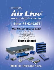
After unpacking and taking out the entire package contents, you should check whether you have got<br />
the following items:<br />
⌧<br />
⌧<br />
⌧<br />
<strong>Live</strong>-<strong>FSH8R</strong> <strong>Fast</strong> <strong>Ethernet</strong> <strong>Switch</strong><br />
One AC power adapter<br />
Support CD-ROM (The PDF version of this User’s Manual can be found within)<br />
If any of these above items is missing or damaged, please contact your local dealer for replacement.<br />
Fig. 2-1 Package Content<br />
4<br />
<strong>Live</strong>-<strong>FSH8R</strong> <strong>Fast</strong> <strong>Ethernet</strong> <strong>Switch</strong> User’s Manual V2.0
2 Preparation before Installation<br />
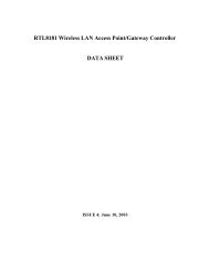
The Front Panel<br />
The front panel is where you can find the LED indicators. For information concerning LED<br />
indicators, please refer to Chapter 5, LED Indicators.<br />
Power LED<br />
Station Port LEDs<br />
Fig. 2-2 Front Panel<br />
The Rear Panel<br />
The rear panel is where you can locate the DC power jack, the 8 10/100Mbps station ports. For the<br />
technical specifications of the ports, please refer to Appendix A, <strong>Product</strong> Specifications for detailed<br />
information.<br />
Station Ports (Port #1 to #8)<br />
<strong>Live</strong>-<strong>FSH8R</strong> <strong>Fast</strong> <strong>Ethernet</strong> <strong>Switch</strong> is equipped with 8 10/100Mbps auto-sensing and<br />
auto-negotiating ports. You can use these ports to connect to end stations, servers or other<br />
networking devices.<br />
DC Power Jack<br />
The DC Power Jack is where you should connect the DC power adapter chord.<br />
Power Connector<br />
Station Ports<br />
Fig. 2-3 Rear Panel<br />
5<br />
<strong>Live</strong>-<strong>FSH8R</strong> <strong>Fast</strong> <strong>Ethernet</strong> <strong>Switch</strong> User’s Manual V2.0
3 Installation of the <strong>Switch</strong><br />
3 Installation of the <strong>Switch</strong><br />
Quick Installation<br />
<strong>Live</strong>-<strong>FSH8R</strong> <strong>Fast</strong> <strong>Ethernet</strong> <strong>Switch</strong> is fully compliant with 10/100BASE-TX <strong>Fast</strong> <strong>Ethernet</strong><br />
standards.<br />
2 Steps to Quick Installation<br />
Step 1. Power on the <strong>Switch</strong>.<br />
Step 2. Connect network devices to the <strong>Switch</strong>: connect either workstation, server, switch, bridge<br />
or router to the station port (10/100BASE-TX), using 100 ohm unshielded twisted pair (category 5<br />
UTP) or shielded twisted-pair (STP) cable.<br />
Desktop Installation<br />
<strong>Live</strong>-<strong>FSH8R</strong> <strong>Fast</strong> <strong>Ethernet</strong> <strong>Switch</strong> has four rubber pads attached on each corner of its underside.<br />
These pads serve as cushionings against vibration and prevent the switch from sliding off its<br />
position. They also allow adequate ventilation space when you place the switch on top of another<br />
device.<br />
Fig. 3-1 Desktop installation<br />
6<br />
<strong>Live</strong>-<strong>FSH8R</strong> <strong>Fast</strong> <strong>Ethernet</strong> <strong>Switch</strong> User’s Manual V2.0
3 Installation of the <strong>Switch</strong><br />
Installation on Wall<br />
<strong>Live</strong>-<strong>FSH8R</strong> <strong>Fast</strong> <strong>Ethernet</strong> <strong>Switch</strong> can be mounted on a wall with wall anchors and screws.<br />
To mount the <strong>Switch</strong> on wall, please follow the steps below:<br />
• Drill two holes, the distance between both of which should be 9 cm (such as the illustration<br />
below).<br />
• Insert wall anchors into these two holes.<br />
• Drive the screws into the top of the wall anchors.<br />
• Mount <strong>Live</strong>-<strong>FSH8R</strong> on the screws.<br />
9 cm<br />
Fig. 3-2 Bottom View of the <strong>Switch</strong> (showing mounting holes)<br />
Cabling Requirements<br />
<strong>Live</strong>-<strong>FSH8R</strong> <strong>Fast</strong> <strong>Ethernet</strong> <strong>Switch</strong> is primarily designed as a central switching device to provide<br />
10/100Mbps bandwidth to your <strong>Ethernet</strong>/<strong>Fast</strong> <strong>Ethernet</strong> LAN.<br />
Cable requirement for 100BASE-TX Port<br />
Those 8 RJ-45 station ports (MDI-X) all require Cat. 5 twisted-pair UTP/STP cable for connection.<br />
When configuring within the 10/100BASE-TX cabling architecture, the cable distance should be<br />
within 100m.<br />
The following table summarizes the cable requirement for 10/100BASE-TX connection:<br />
10BASE-T<br />
100BASE-TX<br />
100 ohm Category 3, 4, 5 UTP/STP cable<br />
100 ohm Category 5 UTP/STP cable<br />
Straight-through cabling<br />
Under most conditions, the 8 station ports on the <strong>Switch</strong> accept normal, straight-through cables, i.e.,<br />
standard UTP/STP cables, which are the only ones that can be used with a RJ-45 connector<br />
interface.<br />
7<br />
<strong>Live</strong>-<strong>FSH8R</strong> <strong>Fast</strong> <strong>Ethernet</strong> <strong>Switch</strong> User’s Manual V2.0
3 Installation of the <strong>Switch</strong><br />
Normally, 10BASE-T networks require a straight-through Cat. 3, 4, 5 UTP/STP cabling system.<br />
The cabling system could be found in most existing <strong>Ethernet</strong> network installations.<br />
100/100BASE-TX networks require Cat. 5 UTP/STP cabling system. The pin assignments for a<br />
straight-through cable are shown in Figure 3-5 and 3-6.<br />
Fig. 3-3 10/100BASE-TX pin assignments for RJ-45 connector<br />
Fig. 3-4 Pin assignments for straight-through cabling<br />
Note:<br />
While connecting<strong>Live</strong>-<strong>FSH8R</strong> to other hub/switch, you don’t have to use a crossover cable for<br />
connection, since <strong>Live</strong>-<strong>FSH8R</strong> performs auto-crossing over by its Auto-MDI, Auto-MDI-X<br />
function. Simply use the straight-through cable for all types of 100BASE-TX connections, either<br />
to a PC or to a networking device such as other hub or switch.<br />
The table below describes when to use straight-through or crossover cable:<br />
Specification<br />
Connection<br />
Interface<br />
Cable to Use<br />
To an end station<br />
To a hub/switch<br />
Maximum Distance<br />
Station Port<br />
10BASE-T/100BASE-T<br />
RJ-45<br />
Straight-through<br />
twisted-pair cable<br />
Straight-through<br />
twisted-pair cable<br />
100 meters<br />
Table 3-1 Cabling type for 10BASE-T/100BASE-TX<br />
8<br />
<strong>Live</strong>-<strong>FSH8R</strong> <strong>Fast</strong> <strong>Ethernet</strong> <strong>Switch</strong> User’s Manual V2.0
3 Installation of the <strong>Switch</strong><br />
Connecting to Power<br />
<strong>Live</strong>-<strong>FSH8R</strong> is accompanied with an external power adapter unit, which is specifically designed for<br />
the line voltage and the type of AC outlet used in your location. This power adapter provides the<br />
voltage, amperage, and polarity required by the <strong>Switch</strong> (7.5V DC @1.5A, inside positive, outside<br />
negative) and is outfitted with the correct type of barrel connector for the DC power jack on the rear<br />
panel.<br />
After verifying that the DC power adapter cord is suitable for use, just plug the male end of the DC<br />
power adapter into a power outlet on the wall; and plug the barrel connector of the power adapter<br />
into DC power jack on the <strong>Switch</strong>. Once you have correctly plugged in the power, the <strong>Switch</strong> is<br />
activated.<br />
Power Connector<br />
Power Outlet<br />
Fig 3-5 Connecting the <strong>Switch</strong> to power outlet<br />
9<br />
<strong>Live</strong>-<strong>FSH8R</strong> <strong>Fast</strong> <strong>Ethernet</strong> <strong>Switch</strong> User’s Manual V2.0
4 Expanding your Network<br />
4 Expanding Your Network<br />
<strong>Live</strong>-<strong>FSH8R</strong> <strong>Fast</strong> <strong>Ethernet</strong> <strong>Switch</strong> is primarily designed as a central switching device to manage<br />
your workgroup/departmental traffic within <strong>Ethernet</strong>/<strong>Fast</strong> <strong>Ethernet</strong>.<br />
Its built-in VLAN function offers instant connection without further administration efforts.<br />
Furthermore, its secure VLAN feature offers security for virtual workgroups. With your existing<br />
<strong>Ethernet</strong>/<strong>Fast</strong> <strong>Ethernet</strong> infrastructure, you can very easily connect, expand or migrate to virtual<br />
workgroup computing in an <strong>Ethernet</strong>/<strong>Fast</strong> <strong>Ethernet</strong> environment.<br />
The following sections will introduce to you the basics of network connectivity in virtual workgroup<br />
computing within <strong>Ethernet</strong>/<strong>Fast</strong> <strong>Ethernet</strong> environment as well as VLAN and priority configuration.<br />
Connectivity Rules<br />
10 Mbps Connection (10BASE-T)<br />
<strong>Ethernet</strong> connection should be configured according to the following connectivity rules:<br />
• The maximum length for UTP cables must not exceed 100 meters from end station to a<br />
shared-access 10BASE-T hub.<br />
• Between any two end stations in a collision domain, there may be up to five cable segments and<br />
four intermediate repeaters at most.<br />
• If there is a path between any two end-stations containing five segments and four repeaters, then<br />
at least two of the cable segments must be point-to-point link segments (e.g. 10BASE-T or<br />
10BASE-5), while the remaining segments may be of mixed segments (e.g.: 10BASE-2 or<br />
10BASE-5).<br />
Twisted-pair 100Mbps Connection (100BASE-TX)<br />
Copper-wired <strong>Fast</strong> <strong>Ethernet</strong> connection should be configured according to the following<br />
connectivity rules:<br />
• The maximum length for STP/UTP cable is 100 meters from end station and a shared-access<br />
100BASE-TX hub.<br />
• The maximum cable length is 100 meters between end station and switch/repeater; and 100<br />
meters between switch and switch/repeater, thus making possible a maximum distance of 300<br />
meters between two end stations.<br />
10<br />
<strong>Live</strong>-<strong>FSH8R</strong> <strong>Fast</strong> <strong>Ethernet</strong> <strong>Switch</strong> User’s Manual V2.0
4 Expanding your Network<br />
Connecting to another <strong>Switch</strong>/Hub<br />
Straight-through Cable Connection for <strong>Switch</strong>-to-<strong>Switch</strong>/hub<br />
Connection<br />
Use a straight-through cable for the connection made through the station port of <strong>Live</strong>-<strong>FSH8R</strong> to any<br />
station port of the other switch/hub. Since <strong>Live</strong>-<strong>FSH8R</strong> <strong>Switch</strong> is capable of auto-crossing over by<br />
its Auto-MDI and Auto-MDI-X function, you don’t have to use a crossover cable such as is usually<br />
required for this kind of switch-to-switch/hub connection with other switch.<br />
Fig. 4-1 Uplink to another <strong>Switch</strong>/Hub using straight-through cable<br />
Summary on Connectivity:<br />
• When connecting a PC/hub/switch or any other networking device to the<br />
10/100BASE-TX station port of the <strong>Live</strong>-<strong>FSH8R</strong>, use a straight-through UTP<br />
cable. No crossover cable is required for <strong>Live</strong>-<strong>FSH8R</strong>. The 10/100BASE-TX<br />
cabling distance is 100 meters maximum.<br />
11<br />
<strong>Live</strong>-<strong>FSH8R</strong> <strong>Fast</strong> <strong>Ethernet</strong> <strong>Switch</strong> User’s Manual V2.0
4 Expanding your Network<br />
Transmission Modes<br />
Station Ports (10/100BASE-TX Transmission)<br />
All 10/100Mbps station ports of <strong>Live</strong>-<strong>FSH8R</strong> <strong>Fast</strong> <strong>Ethernet</strong> <strong>Switch</strong> utilize auto-negotiation to<br />
determine the transmission mode for any new connection. This means, if auto-negotiation is<br />
supported on both ends of the connection, the <strong>Switch</strong> is initiated to negotiate for one of the following<br />
transmission modes:<br />
• 200Mbps/FDX<br />
• 100Mbps/HDX<br />
• 20Mbps/FDX<br />
• 10Mbps/HDX<br />
LAN Micro segmentation through <strong>Switch</strong>ing Technology<br />
<strong>Live</strong>-<strong>FSH8R</strong> <strong>Fast</strong> <strong>Ethernet</strong> <strong>Switch</strong> can effectively segment your network, significantly increasing<br />
both bandwidth and throughput. Any port on the <strong>Switch</strong> can either be attached to a hub (i.e., shared<br />
collision domain) or serve as a dedicated link to a single network device (e.g., a workstation). When<br />
a port on the <strong>Switch</strong> is connected to an <strong>Ethernet</strong> hub (i.e., a 10 or 100 Mbps repeater), the bandwidth<br />
provided by that port is shared by all the devices connected to the attached hub. However, when a<br />
port is connected to an end node or to a device that breaks up the collision domain, e.g., another<br />
<strong>Switch</strong>, bridge or router, the attached device will have access to the full bandwidth provided by that<br />
port.<br />
Micro segmentation of an existing LAN can improve network latency and increase overall<br />
performance.<br />
<strong>Live</strong>-<strong>FSH8R</strong> <strong>Fast</strong> <strong>Ethernet</strong> <strong>Switch</strong> uses Store-and-Forward switching to control network traffic,<br />
thus ensuring data integrity under heavy load.<br />
12<br />
<strong>Live</strong>-<strong>FSH8R</strong> <strong>Fast</strong> <strong>Ethernet</strong> <strong>Switch</strong> User’s Manual V2.0
5 LED Indicators<br />
5 LED Indicators<br />
Before connecting any network device to <strong>Live</strong>-<strong>FSH8R</strong> <strong>Fast</strong> <strong>Ethernet</strong> <strong>Switch</strong>, you should take a few<br />
minutes to look over this chapter and get familiar with the front panel LED indicators of your <strong>Switch</strong>.<br />
The front-panel LED indicators of <strong>Live</strong>-<strong>FSH8R</strong> comprise 2 sets of LEDs: System Status LEDs and<br />
Station Port LEDs. Each set of LEDs gives specific information concerning the system status or the<br />
station port status:<br />
Comprehensive LEDs<br />
System LED<br />
Power LED indicates the system power Status.<br />
Station Port LEDs<br />
Station Port LEDs show the port status of each of its eight 10/100 Mbps station ports. There are<br />
Link/Act, FDX/Col LED, and 100M for each port.<br />
Power LED<br />
Station Port LEDs<br />
Fig. 5-1 Front-panel LED indicators<br />
The specific function of each LED will be described in full details in the following sections:<br />
Power LED<br />
Power LED will give a solid green light when you turn on the <strong>Switch</strong>, and will be off when the<br />
<strong>Switch</strong> being turned off. You can simply check the Power LED to see if the <strong>Switch</strong> is being<br />
activated. Before turning on the <strong>Switch</strong>, please verify that the power cord has been properly<br />
connected to the <strong>Switch</strong> and the power outlet on the wall.<br />
13<br />
<strong>Live</strong>-<strong>FSH8R</strong> <strong>Fast</strong> <strong>Ethernet</strong> <strong>Switch</strong> User’s Manual V2.0
5 LED Indicators<br />
Station Port LEDs<br />
Link/Act LED<br />
Link/Act LED giving a solid green light indicates that a data link has been established between the<br />
corresponding port and the device. If no connection is made, it will be off. While the port is<br />
transmitting or receiving data, you will see a blinking green light.<br />
FDX/Col LED<br />
FDX/Col LED shows the transmission mode of the connection. When in full-duplex transmission<br />
mode, FDX LED gives forth a solid yellow light. When in half-duplex mode, it will be off. While<br />
collisions happen in half-duplex mode, the FDX/Col will be blinking.<br />
100M<br />
100M LED giving a solid red light indicates that a 100Mbps data link has been established between<br />
the corresponding port and the device. If no 100Mbps connection is made, it will be off.<br />
Table 5-1 Station Port LEDs<br />
LED indicator Color Status Meaning<br />
System LEDs<br />
Power LED ● Green ON<br />
OFF<br />
Station Port LEDs<br />
Link/Act ● Green ON<br />
Blinking<br />
OFF<br />
Power ON<br />
Power OFF<br />
Connection is made<br />
Transmitting/Receiving<br />
No connection is made<br />
FDX/Col<br />
●<br />
Yellow<br />
ON<br />
OFF<br />
Blinking<br />
Full Duplex<br />
Half Duplex<br />
Collisions (in half duplex)<br />
100M ● RED ON<br />
OFF<br />
100 Mbps Connection<br />
10 Mbps Connection<br />
14<br />
<strong>Live</strong>-<strong>FSH8R</strong> <strong>Fast</strong> <strong>Ethernet</strong> <strong>Switch</strong> User’s Manual V2.0
Appendix A <strong>Product</strong> Specifications<br />
Appendix A <strong>Product</strong> Specifications<br />
• Standard Compliance<br />
• IEEE 802.3 10BASE-T <strong>Ethernet</strong><br />
• IEEE 802.3u 100BASE-TX <strong>Fast</strong> <strong>Ethernet</strong><br />
• ANSI/IEEE Std 802.3 NWay auto-negotiation<br />
• Topology Star<br />
• Port Configuration<br />
• 8 × 10/100 BASE-TX Port<br />
• Data Rate<br />
• 10BASE-T <strong>Ethernet</strong><br />
10 Megabits/sec (half-duplex)<br />
20 Megabits/sec (full-duplex)<br />
• 100BASE-TX <strong>Fast</strong> <strong>Ethernet</strong><br />
100 Megabits/sec (half-duplex)<br />
200 Megabits/sec (full-duplex)<br />
• Transmission method Store and Forward<br />
• Full Duplex Auto-negotiation<br />
• Active Flow Control<br />
• IEEE 802.3x compliant flow control for full duplex<br />
• Back Pressure for half duplex<br />
• Filtering Address Table 8K<br />
• RAM Buffer 256 KBytes<br />
• MAC Address Learning Automatic update<br />
• Cabling Type<br />
• 10BASE-T: 4-pair 100 ohm Category 3,4,5 UTP (100 m) cable<br />
• 100BASE-TX: 4-pair 100 ohm Category 5 UTP/STP (100 m) cable<br />
• LED layout<br />
• System LEDs<br />
Power LED<br />
• Station port LEDs for port 1 ~ 8<br />
Link/Act LEDs<br />
FDX/Col LEDs<br />
100M LEDs<br />
• Dimensions 209*144*49 m/m<br />
15<br />
<strong>Live</strong>-<strong>FSH8R</strong> <strong>Fast</strong> <strong>Ethernet</strong> <strong>Switch</strong> User’s Manual V2.0
Appendix A <strong>Product</strong>ion Specifications<br />
• Net Weight 450g<br />
• Power Input External Power Supply with +7.5v/1.5.A output<br />
120/220V AC ,50~60 Hz TO DC7.5V/1.5A<br />
• Power Consumption 7.5 Watts max, @ 7.5V DC<br />
• Operating Temperature -32 ~ 122 °F / 0 ~ 50 °C<br />
• Storage Temperature - 68 ~ 149°F / -20 ~ 65 °C<br />
• Humidity < 95% (non-condensing)<br />
• Safety / EMI Certificates UL, TUV, VDE, FCC Class A, CE<br />
16<br />
<strong>Live</strong>-<strong>FSH8R</strong> <strong>Fast</strong> <strong>Ethernet</strong> <strong>Switch</strong> User’s Manual V2.0
Appendix B Troubleshooting<br />
Appendix B Troubleshooting<br />
This appendix contains specific information to help you identify and solve problems.<br />
If your switch does not function properly, please make sure it is set up according to<br />
the instructions on the manual.<br />
If you suspect your switch is not connected correctly to your network, check the<br />
following points before you contact your local dealer for support.<br />
• Make sure the Power is ON (Check the Power LED).<br />
• Make sure the cable is connected properly on both ends.<br />
• Make sure that the maximum cable length between switch and end node<br />
does not exceed 100 meters (for 10/100BASE-TX connection).<br />
• Make sure that the maximum switch-to-hub/switch cable distance does not<br />
exceed 100 meters (for 10/100BASE-TX connection).<br />
• Verify that the cabling type used is correct.<br />
• Check the corresponding Link/Act, FDX/Col, 100M for signs of faulty<br />
connection. Check the status of the cable attachment. If the problem<br />
persists, try a different cable.<br />
• Try another port on the <strong>Switch</strong>.<br />
• Turn off power supply to the <strong>Switch</strong>. After a while, turn it on again to see if<br />
it resumes to its normal function.<br />
• If you find out where the problem is but cannot solve it by yourself, or you<br />
simply cannot locate what is at fault, please contact your local dealer for<br />
technical support.<br />
17<br />
<strong>Live</strong>-<strong>FSH8R</strong> <strong>Fast</strong> <strong>Ethernet</strong> <strong>Switch</strong> User’s Manual V2.0