Ether-FSH2400NS-Manu..
Ether-FSH2400NS-Manu..
Ether-FSH2400NS-Manu..

Create successful ePaper yourself
Turn your PDF publications into a flip-book with our unique Google optimized e-Paper software.
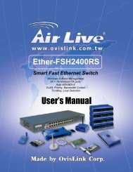
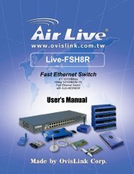
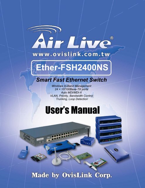
<strong>Ether</strong>-<strong>FSH2400NS</strong><br />
Smart Fast <strong>Ether</strong>net Switch<br />
Windows In-Band Management<br />
24 × 10/100Base-TX ports<br />
Auto MDI/MDI-X<br />
VLAN, Priority, Bandwidth Control<br />
Trunking, Loop Detection<br />
User’s <strong>Manu</strong>al
Trademarks<br />
All rights reserved.<br />
AirLive Logo is an registered trademarks of OvisLink Corp, Taiwan. Other product names<br />
and company names are trademarks or registered trademarks of their respective owners.<br />
FCC Warning<br />
This equipment has been tested and found to comply with the requirements for a Class A<br />
digital device, pursuant to Part 15 of the FCC Rules. These requirements are designed for<br />
reasonable protection against harmful interference when the equipment operating in a<br />
commercial environment. This equipment can generate and radiate electromagnetic energy<br />
and, if not installed and used in accordance with this guide, may cause significant<br />
interference with radio communication. Operation of this equipment in a residential area is<br />
likely to cause interference to household appliances, in which case the user will be required<br />
to amend at his or her own expense.<br />
CE Mark Warning<br />
This is a Class A product. In a domestic environment, this product may cause radio<br />
interference, in which case the user may be required to take adequate preventive measures.<br />
Disclaimer<br />
Contents in this manual are subject to changes without prior notice.<br />
About this User’s <strong>Manu</strong>al<br />
This User’s <strong>Manu</strong>al aims at helping users to know the key features of<br />
<strong>Ether</strong>-<strong>FSH2400NS</strong> Fast <strong>Ether</strong>net Switch and to install it in a<br />
10/100BASE-TX Fast <strong>Ether</strong>net Local Area Network (LAN).<br />
OvisLink Corp<br />
2F, No. 8, Lane 130, Min-Chuan Rd, Hsin-Tien City, Taipei, Taiwan, R.O.C.
Table of Contents<br />
Table of Contents<br />
TABLE OF CONTENTS ........................................................................................I<br />
1 PRODUCT<br />
OVERVIEW ........................................................................1<br />
Introduction....................................................................................................................... 1<br />
Windows Remote Management software ....................................................................... 1<br />
Management Features ...................................................................................................... 1<br />
Per-port bandwidth control................................................................................................. 1<br />
Central Switch management:.............................................................................................. 1<br />
VLAN filter ...................................................................................................................... 1<br />
Quality of Service.............................................................................................................. 1<br />
Link aggregation ............................................................................................................... 1<br />
IGMP Snooping ................................................................................................................ 1<br />
Broadcast Storm control..................................................................................................... 1<br />
Loop detection .................................................................................................................. 1<br />
Port setting........................................................................................................................ 2<br />
Authentication Keys .......................................................................................................... 2<br />
In-Band and Out-of-Band Management......................................................................... 2<br />
What is VLAN?................................................................................................................. 2<br />
Defining VLAN .............................................................................................................. 2<br />
Port-based VLAN ........................................................................................................... 2<br />
Table Maintenance via Signaling.................................................................................... 3<br />
What is Priority Queuing? ............................................................................................... 3<br />
2 PREPARATION<br />
BEFORE INSTALLATION.........................................4<br />
i<br />
<strong>Ether</strong>-<strong>FSH2400NS</strong> Fast <strong>Ether</strong>net Switch User’s <strong>Manu</strong>al V1.0
Table of Contents<br />
Unpack the Package.......................................................................................................... 4<br />
The Front Panel.................................................................................................................5<br />
Reset Button ...................................................................................................................... 5<br />
The Rear Panel..................................................................................................................5<br />
Power Switch .................................................................................................................. 5<br />
AC Power Connector ...................................................................................................... 6<br />
3 INSTALLATION<br />
OF THE SWITCH.......................................................7<br />
Quick Installation..............................................................................................................7<br />
5 Steps to Quick Installation........................................................................................... 7<br />
Rack Mounting.................................................................................................................. 7<br />
Desktop Installation.......................................................................................................... 8<br />
Installation Site Preparation............................................................................................ 8<br />
Cabling Guide.................................................................................................................... 9<br />
For 10/100BASE-TX ports............................................................................................. 9<br />
Auto MDI/MDI-X function ............................................................................................ 9<br />
Making your own UTP/STP cable.................................................................................. 9<br />
Connecting to Power....................................................................................................... 10<br />
4 LED<br />
INDICATORS..............................................................................12<br />
System LEDs.................................................................................................................... 12<br />
Station Port LEDs ........................................................................................................... 12<br />
LED Table........................................................................................................................ 13<br />
ii<br />
<strong>Ether</strong>-<strong>FSH2400NS</strong> Fast <strong>Ether</strong>net Switch User’s <strong>Manu</strong>al V1.0
Table of Contents<br />
5 MANAGEMENT SOFTWARE GUIDE ...................................................14<br />
Introduction..................................................................................................................... 14<br />
Important Information................................................................................................... 14<br />
Minimum system requirements..................................................................................... 14<br />
Hardware....................................................................................................................... 14<br />
Software ........................................................................................................................ 14<br />
Installing the Software.................................................................................................... 15<br />
Starting the Software...................................................................................................... 16<br />
Switch Status Functions ................................................................................................. 18<br />
Port Status Submenu..................................................................................................... 18<br />
MIB Information Submenu........................................................................................... 19<br />
Cable Tester .................................................................................................................. 20<br />
Signal Quality ............................................................................................................... 21<br />
Switch Configuration...................................................................................................... 21<br />
Global Configuration Submenu .................................................................................... 22<br />
Loop Port Detection ........................................................................................................... 22<br />
Port Configuration Submenu ........................................................................................ 23<br />
Trunking .......................................................................................................................... 24<br />
Qos Configuration Submenu......................................................................................... 24<br />
VLAN Configuration Submenu.................................................................................... 26<br />
Port Base VLAN........................................................................................................... 27<br />
Port Mirror Configuration............................................................................................. 28<br />
Security Configuration.................................................................................................. 29<br />
Switch Internals .............................................................................................................. 30<br />
Load Factory Default Settings ...................................................................................... 30<br />
Save Configuration to Hardware .................................................................................. 30<br />
Device Reset ................................................................................................................. 30<br />
APPENDIX A PRODUCT SPECIFICATIONS ..................................................31<br />
APPENDIX B TROUBLESHOOTING...............................................................33<br />
iii<br />
<strong>Ether</strong>-<strong>FSH2400NS</strong> Fast <strong>Ether</strong>net Switch User’s <strong>Manu</strong>al V1.0
Table of Contents<br />
Figures<br />
Fig. 2-1 Package Contents .............................................................................................. 4<br />
Fig. 2-2 Front Panel ....................................................................................................... 5<br />
Fig 2-3 The Reset Button............................................................................................... 5<br />
Fig. 2-4 Rear Panel ......................................................................................................... 6<br />
Fig. 3-1 Fastening the brackets on the switch................................................................. 7<br />
Fig. 3-2 Attaching the Switch to a 19-inch rack ............................................................. 8<br />
Fig. 3-3 Desktop installation........................................................................................... 8<br />
Fig 3-13 Connecting the Switch to power outlet .......................................................... 11<br />
iv<br />
<strong>Ether</strong>-<strong>FSH2400NS</strong> Fast <strong>Ether</strong>net Switch User’s <strong>Manu</strong>al V1.0
Table of Contents<br />
Tables<br />
Table 2-2 Cabling type for 10/100BASE-TX................................................................. 9<br />
Table 4-1 System & Station Port LEDs........................................................................ 13<br />
v<br />
<strong>Ether</strong>-<strong>FSH2400NS</strong> Fast <strong>Ether</strong>net Switch User’s <strong>Manu</strong>al V1.0
1 Product Overview<br />
1 Product Overview<br />
Introduction<br />
Windows Remote Management software<br />
Conventionally, configuring a switch's smart management will require users to attach the computer<br />
(serial or printer port) directly to the switch's console port. With <strong>Ether</strong>-<strong>FSH2400NS</strong>'s in-band<br />
management capability, users can configure the switch through the <strong>Ether</strong>net network. The included<br />
Windows management software provides a very simple point-and-click interface to set all the<br />
functions. Users can even backup settings to be restored in the future. Best of all, the management<br />
utility can configure several switches using the same utility.<br />
Management Features<br />
The <strong>Ether</strong>-<strong>FSH2400NS</strong> is equipped with many practical management functions.<br />
Per-port bandwidth control<br />
• allow limiting the outgoing and incoming bandwidth separately for each port .<br />
Central Switch management:<br />
• Configure several switches at the same time.<br />
VLAN filter<br />
• provide controls to let single-cast, multi-cast, or broadcast traffic to pass between<br />
VLANs.<br />
Quality of Service<br />
• for multimedia applications: the 802.1p compliance provide priority traffic<br />
management based on port, vlan-tag, or TCP/IP Differserv information.<br />
Link aggregation<br />
• The LACP(Link Aggregation Control Protocol) increase the uplink speed by allowing<br />
several ports(Trunk Group) to link between the switches. The switch allows up to 7<br />
trunk groups in 2 or 4 ports. Please make sure that switches on both side are setup for<br />
the trunking function.<br />
IGMP Snooping<br />
• for IP multicast group management<br />
Broadcast Storm control<br />
• prevents the broadcast traffic from overflowing the network.<br />
Loop detection<br />
1<br />
<strong>Ether</strong>-<strong>FSH2400NS</strong> Fast <strong>Ether</strong>net Switch User’s <strong>Manu</strong>al V1.0
1 Product Overview<br />
• alert the user when there is a loop formed inside the network on the front panel LED.<br />
• The management software's diagnostic function even report which ports the loop<br />
occurs.<br />
Port setting<br />
• setting port speed and duplex mode, flow control<br />
Authentication Keys<br />
• The switch support authentication key feature for the management function. This will<br />
prevent unauthorized users from changing the switch’s settings.<br />
For Detail information on management functions, please refer to Chapter 5 “Management<br />
Software Guide”.<br />
In-Band and Out-of-Band Management<br />
In-Band and Out-of-Band managements are the two distinct methods for switch management.<br />
In-Band management that includes WinSmart, Web, Telnet, and SNMP allows users to configure<br />
the switch through the <strong>Ether</strong>net network.<br />
Out-of-Band management means managing the switch outside of the switch’s <strong>Ether</strong>net network.<br />
Console Port management is the most common type of out-of-band management. Out-of-Band<br />
management requires the switch to be physically attached to a computer through a RS-232, USB, or<br />
Parallel port.<br />
The <strong>Ether</strong>-<strong>FSH2400NS</strong> is equipped with WinSmart In-band management. It uses the unique RRCP<br />
protocol that enables the included Windows utility to manage the switch inside the LAN. However;<br />
since it does not use IP protocol, it cannot be managed remotely from the Internet.<br />
What is VLAN?<br />
Defining VLAN<br />
What is VLAN? Since VLAN solutions and implementations are still very vendor-specific, to define<br />
precisely what VLANs will certainly arouse controversy. Nevertheless, most would agree that a<br />
VLAN can roughly be equated as a broadcast domain. More specifically, VLANs can be seen as a<br />
group of end stations, perhaps on multiple physical LAN segments, which are not constrained by<br />
their physical location and can communicate as if they were on a common LAN.<br />
There are several ways to define VLAN membership: port grouping, frame tagging, MAC-layer<br />
grouping, network-layer grouping, IP multicast grouping, etc. <strong>Ether</strong>-<strong>FSH2400NS</strong> utilizes<br />
port-grouping (port-based VLAN) for the implementation of VLAN in your network.<br />
Port-based VLAN<br />
<strong>Ether</strong>-<strong>FSH2400NS</strong> Fast <strong>Ether</strong>net Switch fulfills the initial VLAN implementation as defining<br />
VLAN membership by groups of switch ports. Port grouping is the most common method of<br />
defining VLAN membership, and its configuration is straightforward. But, when a user moves from<br />
one port to another, it takes a network manager to manually reconfigure VLAN membership.<br />
2<br />
<strong>Ether</strong>-<strong>FSH2400NS</strong> Fast <strong>Ether</strong>net Switch User’s <strong>Manu</strong>al V1.0
1 Product Overview<br />
With manual VLAN configuration, both the initial setup and all subsequent moves and changes are<br />
controlled by the network administrator, enabling a high degree of control. Also moving users<br />
manually with VLANs may actually be easier than moving users across router subnets.<br />
Table Maintenance via Signaling<br />
When an end-station broadcasts its first frame, the switch resolves the end-station’s attached port<br />
with its VLAN membership in cached address tables. As VLAN membership changes, these address<br />
tables can be manually updated by a system administrator at a management console.<br />
What is Priority Queuing?<br />
Priority Queuing is a method of ensuring that high priority traffic gets delivered efficiently, even<br />
when during bursts of high traffic load. In this way, traffic such as voice data and video (services<br />
which are streaming) are prioritized, helping steady picture and sound quality.<br />
<strong>Ether</strong>-<strong>FSH2400NS</strong> allows 2-level (High/Normal) Priority setting by any of the three types of<br />
priority frames operations: TCP/IP TOS or per Port priority frame operation.<br />
The QoS setting for priority per port means that all packets received by the port will be priority<br />
frames; <strong>Ether</strong>-<strong>FSH2400NS</strong> can also judge the priority of frames by checking the specific bits of r<br />
TCP/IP TOS/DS included in the frame format. <strong>Ether</strong>-<strong>FSH2400NS</strong> will judge the priority of frames<br />
by checking the specific bits recorded in the type field of packet format to ensure the VLAN or<br />
TCP/IP TOS/DS status of packets, then set the threshold of VLAN or TCP/IP TOS/DS to declare the<br />
priority of packet.<br />
If you have any plans to implement network telephony or any sort of video conferencing,<br />
streaming video/audio or any real-time applications on your network you will need<br />
<strong>Ether</strong>-<strong>FSH2400NS</strong> for priority queuing. Its benefit is to dramatically improve the quality<br />
of priority services on the network. If priority queuing is not implemented then the quality<br />
of these services will depend entirely on the loads on your network. If network traffic is<br />
high, the service will not work properly.<br />
3<br />
<strong>Ether</strong>-<strong>FSH2400NS</strong> Fast <strong>Ether</strong>net Switch User’s <strong>Manu</strong>al V1.0
2 Preparation before Installation<br />
2 Preparation before Installation<br />
Unpack the Package<br />
Before you begin the installation of <strong>Ether</strong>-<strong>FSH2400NS</strong> Fast <strong>Ether</strong>net Switch, make sure that you<br />
have all the necessary accessories that come with your package. Follow the steps below to unpack<br />
your package contents:<br />
1. Clear out an adequate space to unpack the package carton.<br />
2. Open the package carton and take out the contents carefully.<br />
3. Put back all the shipping materials such as plastic bag, paddings and linings into the package<br />
carton and save them for future transport need.<br />
After unpacking and taking out the entire package contents, you should check whether you have got<br />
the following items:<br />
⌧<br />
⌧<br />
⌧<br />
⌧<br />
<strong>Ether</strong>-<strong>FSH2400NS</strong> Fast <strong>Ether</strong>net Switch<br />
One AC power cord<br />
Rack-mounting kit (screws and mounting brackets)<br />
Support CD-ROM (The PDF version of this User’s <strong>Manu</strong>al can be found within)<br />
If any of these above items is missing or damaged, please contact your local dealer for replacement.<br />
Fig. 2-1 Package Contents<br />
4<br />
<strong>Ether</strong>-<strong>FSH2400NS</strong> Fast <strong>Ether</strong>net Switch User’s <strong>Manu</strong>al V1.0
2 Preparation before Installation<br />
The Front Panel<br />
The front panel is where you can find the twenty-four 10/100Mbps station ports and the LED<br />
indicators. For the technical specifications of the ports, please refer to Appendix A, Product<br />
Specifications for detailed information. For information concerning LED indicators, please refer to<br />
Chapter 4, LED Indicators.<br />
Power LED<br />
Station Port LEDs<br />
Station Ports<br />
DIAG LED<br />
Fig. 2-2 Front Panel<br />
Reset Button<br />
The <strong>Ether</strong>-<strong>FSH2400NS</strong> Features a reset button that can restore the switch settings back to factory’s<br />
default value. Please press this button if your management software have problem detecting the<br />
switch or if the switch is not functioning correctly. The reset button is located on the right side of the<br />
front panel<br />
Fig 2-3 The Reset Button<br />
The Rear Panel<br />
The rear panel is where you can locate the power switch and AC power connector.<br />
Power Switch<br />
You can turn the power switch on /off to activate/deactivate the Switch. To turn on the Switch, press<br />
the switch to the ON position. To turn off, press the switch to the OFF position.<br />
5<br />
<strong>Ether</strong>-<strong>FSH2400NS</strong> Fast <strong>Ether</strong>net Switch User’s <strong>Manu</strong>al V1.0
2 Preparation before Installation<br />
AC Power Connector<br />
This is a three-pronged power connector where the power cord should be attached. Just plug the<br />
female end of the power cord into the connector, and the male end of the power cord into an AC<br />
power outlet. The switch supports an input voltages ranging from 100 ~ 240 V AC @ 50~60 Hz .<br />
Power Switch<br />
Fig. 2-4 Rear Panel<br />
Power Connector<br />
6<br />
<strong>Ether</strong>-<strong>FSH2400NS</strong> Fast <strong>Ether</strong>net Switch User’s <strong>Manu</strong>al V1.0
3 Installation of the Switch<br />
3 Installation of the Switch<br />
Quick Installation<br />
<strong>Ether</strong>-<strong>FSH2400NS</strong> Fast <strong>Ether</strong>net Switch is fully compliant with 10/100BASE-TX Fast <strong>Ether</strong>net<br />
standards.<br />
5 Steps to Quick Installation<br />
Step 1. Power on the Switch.<br />
Step 2. Connect network devices to the Switch: connect either workstation, server, switch, bridge<br />
or router to the station port (10/100BASE-TX), using 100 ohm unshielded twisted pair (category 5<br />
UTP) or shielded twisted-pair (STP) cable.<br />
Step 3. Install the Management software: Please refer to chapter 5 for detail instruction on how to<br />
install and configure the management software.<br />
Rack Mounting<br />
<strong>Ether</strong>-<strong>FSH2400NS</strong> Fast <strong>Ether</strong>net Switch can also be mounted on a standard size 19-inch rack,<br />
which can in turn be placed in a wiring closet with other equipments.<br />
Before you can mount the switch on the rack, first you must attach the mounting brackets on both<br />
sides of the switch with screws, and then mount it as a unit on the rack.<br />
To mount the unit on a rack, please follow the steps below:<br />
Step 1.<br />
Step 2.<br />
Step 3.<br />
Step 4.<br />
First, align the holes on the bracket with the holes on both side of the switch.<br />
Insert screws into the holes and then fasten the bracket on one side of the switch with a<br />
screwdriver.<br />
Repeat Step 1 and 2 to fasten the bracket on the other side of the switch.<br />
Mount the unit on the rack and align the notches on both brackets with mounting holes<br />
on the rack, and then secure the unit with suitable screws.<br />
Fig. 3-1 Fastening the brackets on the switch<br />
7<br />
<strong>Ether</strong>-<strong>FSH2400NS</strong> Fast <strong>Ether</strong>net Switch User’s <strong>Manu</strong>al V1.0
2 Preparation before Installation<br />
Fig. 3-2 Attaching the Switch to a 19-inch rack<br />
Desktop Installation<br />
<strong>Ether</strong>-<strong>FSH2400NS</strong> Fast <strong>Ether</strong>net Switch has four rubber pads attached on each corner of its<br />
underside. These pads serve as cushionings against vibration and prevent the switch from sliding off<br />
its position. They also allow adequate ventilation space when you place the switch on top of another<br />
device.<br />
Fig. 3-3 Desktop installation<br />
• The location you choose to install your switch and the way you configure your network<br />
may greatly affect its performance.<br />
Installation Site Preparation<br />
You can mount <strong>Ether</strong>-<strong>FSH2400NS</strong> Fast <strong>Ether</strong>net Switch either on desktop or on a 19-inch rack. If<br />
you plan to mount the switch on desktop, please choose a steady, level surface in a well-ventilated<br />
area that is free from excessive dust. In any case, the installation site chosen for your switch has to<br />
comply with the following requirements:<br />
• The surface where you want to mount the switch must be able to sustain at least 2.7 kg.<br />
• Do not place heavy objects on top of the switch.<br />
• The location must preferably be free from excessive dust, away from heat vent, hot-air exhaust<br />
and direct sunlight.<br />
8<br />
<strong>Ether</strong>-<strong>FSH2400NS</strong> Fast <strong>Ether</strong>net Switch User’s <strong>Manu</strong>al V1.0
3 Installation of the Switch<br />
• The switch should not be placed near large electric motors or other strong electromagnetic<br />
sources. As a reference, the strength of the electromagnetic field on site should not exceed the<br />
(RFC) standards for IEC 801-3, Level 2(3V/M) field strength.<br />
• The air temperature in the location should be within a range of 32 to 122 °F (0 to 55°C).<br />
• The relative humidity in the location should not exceed 95% non-condensing humidity.<br />
• The distance between the RJ-45 port and the standard network interface should not exceed 100<br />
meters.<br />
• Adequate space should be allowed in front of all the ports, so that each port is easily accessible<br />
for cable connections.<br />
Cabling Guide<br />
For 10/100BASE-TX ports<br />
The 24 RJ-45 station ports require Cat. 5 twisted-pair UTP/STP cable for connection. When<br />
configuring within the 10/100BASE-TX cabling architecture, the cable distance should be within<br />
100m.<br />
The following table summarizes the cable requirement for 10/100BASE-TX connection:<br />
10BASE-T<br />
100BASE-TX<br />
100 ohm Category 3, 4, 5 UTP/STP cable<br />
100 ohm Category 5 UTP/STP cable<br />
Auto MDI/MDI-X function<br />
The SNMP-<strong>FSH2400NS</strong> is equipped with Auto-MDI/MDI-X function, which allows you to use<br />
straight-thru cable even when connecting to another switch/hub. Simply use the straight-through<br />
cable for all types of 10/100BASE-TX connections, either to a PC or to a networking device such as<br />
other hub or switch.<br />
Specification<br />
Interface<br />
Cable to Use<br />
To an end station<br />
To a hub/switch<br />
Maximum Distance<br />
Connection<br />
10 /100Base-TX<br />
Ports<br />
RJ-45<br />
Straight-through twisted-pair cable<br />
Straight-through twisted-pair cable<br />
100 meters<br />
Table 2-2 Cabling type for 10/100BASE-TX<br />
Making your own UTP/STP cable<br />
9<br />
<strong>Ether</strong>-<strong>FSH2400NS</strong> Fast <strong>Ether</strong>net Switch User’s <strong>Manu</strong>al V1.0
2 Preparation before Installation<br />
The twisted-pair cable provided an eight-pin plug at each end that mate with the twisted-pair port on<br />
the adapter and with a RJ-45 wall jack. If you are marking your own interface cables to use as<br />
dedicated network wiring or as extension cables, please follow the guideline below:<br />
<br />
<br />
Each UTP/STP cable contains eight wires in either 568A or<br />
568B color scheme (please see Fig 2-7). The wires are<br />
twisted in pairs to reduce cross talk and various signal<br />
noises.<br />
Each pairs composed of one positive wire and one negative<br />
wire. The positive are marked by stripe color while the<br />
negative are marked by solid color. A pair of wires is<br />
composed of one stripe and one solid wire of the same color.<br />
There are four pairs of wires, they are in group of {1 and 2},<br />
{3 and 6},{4 and 5},{7 and 8}. Please see Fig 2-8 for<br />
diagram.<br />
<br />
<br />
<br />
<br />
When making a cable, make sure the correct pairs of wire are<br />
twisted together before inserting into the jack. Incorrect<br />
twisted pair will cause the cable to malfunction or signal<br />
degradation over short distance.<br />
A straight-thru cable have jacks on both end following<br />
the same color scheme.<br />
A cross-over cable have jacks on both end following the<br />
opposite color scheme (one 568A and one 568B)<br />
While 10/100Base-TX only use the first 2 pairs of wires<br />
(1+2, 3+6). However, please still make sure all 4 pairs<br />
are twisted and insert into the jack in correct order.<br />
Fig 2-3 Twisted Pair<br />
Color Scheme<br />
Fig 2-4 Pair Wires<br />
Connecting to Power<br />
<strong>Ether</strong>-<strong>FSH2400NS</strong> Fast <strong>Ether</strong>net Switch features a universal auto-select power supply unit, which<br />
allows a power connection to a wide range of input voltages from 90 to 240V AC @ 50 ~ 60Hz.<br />
To establish its power connection, simply plug the female end of the power cord into the power<br />
connector on the rear of the switch and the male end of the power cord into a suitable power outlet.<br />
Once you have correctly plugged in the power, you can then turn on the Power Switch to activate the<br />
switch.<br />
10<br />
<strong>Ether</strong>-<strong>FSH2400NS</strong> Fast <strong>Ether</strong>net Switch User’s <strong>Manu</strong>al V1.0
3 Installation of the Switch<br />
Power Switch<br />
Power Connector<br />
Power Outlet<br />
Fig 3-13 Connecting the Switch to power outlet<br />
11<br />
<strong>Ether</strong>-<strong>FSH2400NS</strong> Fast <strong>Ether</strong>net Switch User’s <strong>Manu</strong>al V1.0
4 LED Indicators<br />
4 LED Indicators<br />
Before connecting any network device to <strong>Ether</strong>-<strong>FSH2400NS</strong> Fast <strong>Ether</strong>net Switch, you should take<br />
a few minutes to look over this chapter and get familiar with the front panel LED indicators of your<br />
Switch.<br />
System LEDs<br />
- Power (green) to indicate power on/off status<br />
- Loop (yellow) to indicate network loop has formed inside the network. You can use<br />
the management program’s diagnostic function to find out which port the loop occurs.<br />
This function will work only after you enabled the Loop Detection using the<br />
Management Utility.<br />
- Trunk (RED) indicate when the Trunking function is enabled using the management<br />
utilty<br />
Station Port LEDs<br />
For port 1 ~ port 24<br />
- Link/Act (green) to indicate linking status and activity<br />
- FDX/Col (yellow) to indicate Full Duplex transmission mode and collision status<br />
- 100 M LED (red) to indicate 100 Mbps speed<br />
12<br />
<strong>Ether</strong>-<strong>FSH2400NS</strong> Fast <strong>Ether</strong>net Switch User’s <strong>Manu</strong>al V1.0
4 LED Indicators<br />
LED Table<br />
LED indicator Color Status Meaning<br />
System LEDs<br />
Power LED<br />
● Green<br />
ON<br />
OFF<br />
Power ON<br />
Power OFF<br />
Loop LED<br />
● Yellow<br />
ON<br />
OFF<br />
Detect a loop even in the network<br />
Loop not detected<br />
Trunk LED<br />
● Yellow<br />
ON<br />
Flashing<br />
OFF<br />
Station Port<br />
LEDs<br />
Link/Rx ● Green ON<br />
Blinking<br />
OFF<br />
FDX/Col ● Yellow ON<br />
Blinking<br />
OFF<br />
100M ● Red ON<br />
OFF<br />
Trunk link is established<br />
Trunk function is turn on but<br />
connection is wrong<br />
Connection is made<br />
Transmitting/Receiving<br />
No connection is made<br />
Full Duplex<br />
Collision (in half duplex)<br />
Half Duplex<br />
100Mbps speed<br />
10Mbps speed<br />
Table 4-1 System & Station Port LEDs<br />
13<br />
<strong>Ether</strong>-<strong>FSH2400NS</strong> Fast <strong>Ether</strong>net Switch User’s <strong>Manu</strong>al V1.0
5 Management Software Guide<br />
5 Management Software Guide<br />
Introduction<br />
The Airlive Windows remote management software allows user to configure the management<br />
function though the LAN port. It uses a specialized RRCP protocol and does not use the IP protocol.<br />
It operates inside the <strong>Ether</strong>net network. Comparing to the <strong>Ether</strong>-FSH2400R, the <strong>Ether</strong>-<strong>FSH2400NS</strong><br />
includes a memory management unit (MPU) to allow switch settings be stored inside the flash<br />
memory and enable the authentication key function.<br />
Important Information<br />
• WinPCap 3.1 (included in the CD) must be installed before using the management software<br />
• Most of the setting options show up when you right click on the screen using your mouse.<br />
• Please make sure to press the “Apply” button after changes<br />
• Please make sure to “write to the switch” after change settings<br />
• The <strong>Ether</strong>-<strong>FSH2400NS</strong> has a factory reset button on the right side of the front panel. This<br />
button will restore switch’s setting to factory’s default values.<br />
• If your management program can’t find the switch, please press the reset button.<br />
Minimum system requirements<br />
To use Remote Management Application, it is necessary that your system include the following<br />
components:<br />
Hardware<br />
• Pentium class processor<br />
• 128 MB RAM<br />
Software<br />
• Windows® 98 SE, Win2000, or WinXP<br />
• WinPCap 3.1 (included in the CD)<br />
14<br />
<strong>Ether</strong>-<strong>FSH2400NS</strong> Fast <strong>Ether</strong>net Switch User’s <strong>Manu</strong>al V1.0
5 Management Software Guide<br />
Installing the Software<br />
Please follow the procedures below to install the management program into your Windows<br />
1. Insert the Airlive CD into your computer, the Product CD menu should show up automatically.<br />
If not, on the File Explorer, please click on “setup.exe” to begin.<br />
2. Click on “ETHER/SNMP Series” and select the “<strong>Ether</strong>-<strong>FSH2400NS</strong>”<br />
3. Follow the instruction on screen to install the “WinPCap”. You only have to install it once. If<br />
you installed WinPCAP 3.0 before, please remove it. Then install the one that is included on<br />
the CD.<br />
4. After this you can click on the “Management Utility” on the CD to start the management<br />
software.<br />
15<br />
<strong>Ether</strong>-<strong>FSH2400NS</strong> Fast <strong>Ether</strong>net Switch User’s <strong>Manu</strong>al V1.0
5 Management Software Guide<br />
Starting the Software<br />
1. To start Management Application, please click on “Run Management Software” button on the<br />
CD-ROM<br />
2. The follow screen will appear. Please select a network interface card (choose the one that has<br />
a IP address) and select a switch from the pull down menu. After you select, the switch<br />
configuration menu will appear. Make sure your switch is turned on before using the utility.<br />
16<br />
<strong>Ether</strong>-<strong>FSH2400NS</strong> Fast <strong>Ether</strong>net Switch User’s <strong>Manu</strong>al V1.0
5 Management Software Guide<br />
3. You can add the switch to the database. So you can access quickly the next time. To do so,<br />
please right click on the switch. Then select “Add to Switch Database”. You can give a name<br />
to the switch and change the password during the process.<br />
4. You can also manually enter a switch by click on the Switch Database tab. Then right click on<br />
the white area.<br />
17<br />
<strong>Ether</strong>-<strong>FSH2400NS</strong> Fast <strong>Ether</strong>net Switch User’s <strong>Manu</strong>al V1.0
5 Management Software Guide<br />
There are 4 major functions on the management screen “Network”, “Switch Status”, “Switch<br />
Configuration”, and “Switch Internals”. We will discuss them in the following sections. Please<br />
make sure to save to the hardware after changes.<br />
Switch Status Functions<br />
Click on the Switch Status Tab of the management screen will bring you the overview, port status,<br />
and MIB counter sub menus.<br />
Port Status Submenu<br />
18<br />
<strong>Ether</strong>-<strong>FSH2400NS</strong> Fast <strong>Ether</strong>net Switch User’s <strong>Manu</strong>al V1.0
5 Management Software Guide<br />
The port status includes port type, enabled status, link status, speed duplex, flow control, loop<br />
detection, and the “Router Port” for the IGMP function.<br />
MIB Information Submenu<br />
The function of the MIB counter is to let users see the ongoing traffic of each port. Users can set to<br />
monitor the Transmitting (TX), Receiving (RX), and diagnostic packets separately. Furthermore,<br />
you can even choose to monitor all packets or just collision/error packets. Please remember to right<br />
click each port to change units.<br />
Start<br />
Press this button to start counting packets<br />
Stop<br />
Press this button to stop Byte count<br />
Clear<br />
To clear the current content<br />
Pause<br />
Pause to see the current result.<br />
To Change the Unit or Packet Type. Please right click on any of the ports and make your<br />
selection below:<br />
19<br />
<strong>Ether</strong>-<strong>FSH2400NS</strong> Fast <strong>Ether</strong>net Switch User’s <strong>Manu</strong>al V1.0
5 Management Software Guide<br />
Byte: The unit display is in number of bytes<br />
Packet: The unit display is in number of packets<br />
CRC Error Packet: The MIB information show the number of CRC Error<br />
Collision Packet: The MIB information show the number Collision Packet.<br />
Cable Tester<br />
The “cable tester” function tests the quality of the cable and whether the cable length has exceed the<br />
limit that can be handled by the switch. Please make sure at least one of the port is connected<br />
correctly.<br />
20<br />
<strong>Ether</strong>-<strong>FSH2400NS</strong> Fast <strong>Ether</strong>net Switch User’s <strong>Manu</strong>al V1.0
5 Management Software Guide<br />
Signal Quality<br />
This test whether the electrical signal on each port is good or bad.<br />
Switch Configuration<br />
Choose the Switch Configuration menu will bring various configuration submenus for the switch.<br />
21<br />
<strong>Ether</strong>-<strong>FSH2400NS</strong> Fast <strong>Ether</strong>net Switch User’s <strong>Manu</strong>al V1.0
5 Management Software Guide<br />
Global Configuration Submenu<br />
Global Configuration is used to configure the global port control registers. Press the Refresh button<br />
to read the status of the registers. Press the Update button to set the registers as shown in this frame.<br />
Broadcast Flow<br />
This define whether to enable flow control for the broadcast packet<br />
Loop Port Detection<br />
You must enable this option first before the “Loop” LED function will work. If you want to use the<br />
loop detection function, please enable this option and save settings to the switch. Once this function<br />
is enabled, the Loop LED will light up when there is a loop formed in your network.<br />
IGMP Snooping<br />
Setting IGMP Snooping Control register and IP Multicast Router Port Discovery register. The<br />
router port is displayed in the Switch Status -> Port Status menu.<br />
Broadcast Storm Filter<br />
The Switch will filter out the broadcast packets once it exceeds 5% of total traffic. You can choose<br />
to enable or disable this option<br />
Multicast Flow Control<br />
This define whether to enable flow control for the multi-cast packet<br />
22<br />
<strong>Ether</strong>-<strong>FSH2400NS</strong> Fast <strong>Ether</strong>net Switch User’s <strong>Manu</strong>al V1.0
5 Management Software Guide<br />
Port Configuration Submenu<br />
Press the “Port Configuration” submenu, and you will see a dialog like follows. Put the check in the<br />
item you want to configure.<br />
To Configure, please right click on a port. Then the following menu will appear!<br />
23<br />
<strong>Ether</strong>-<strong>FSH2400NS</strong> Fast <strong>Ether</strong>net Switch User’s <strong>Manu</strong>al V1.0
5 Management Software Guide<br />
Enable:<br />
The default is to enable the port. Check the “Disable” if you want to disconnect the port<br />
Tx Bandwidth Control<br />
Enable this function will restrict the given port’s sending speed to the selected value.<br />
Rx Bandwidth Control<br />
Enable this function will restrict the give port’s receiving speed to the selected value<br />
Advertised Speed<br />
Changing the speed and duplex mode of a given port.<br />
Pause Flow Control<br />
Enable or Disable the pause frame from control. The default is enabled for both RX/TX. This<br />
option needs to be enabled for the Rate Control to work.<br />
Trunking<br />
Enable the Trunking group for this particular port. Trunking combines multiple ports into one<br />
single port. The Trunk group table is as followed:<br />
Group<br />
Ports<br />
Trunk 0 1, 2, 13, 14<br />
Trunk 1 3, 4, 15, 15<br />
Trunk 2 5, 6, 17, 18<br />
Trunk 3 7, 8, 19, 20<br />
Trunk 4 9, 10, 21, 22<br />
Trunk 5 11, 12, 23, 24<br />
*Please make sure to press “Apply” after making changes.<br />
Qos Configuration Submenu<br />
Qos Configuration is used to configure the Qos control registers.<br />
24<br />
<strong>Ether</strong>-<strong>FSH2400NS</strong> Fast <strong>Ether</strong>net Switch User’s <strong>Manu</strong>al V1.0
5 Management Software Guide<br />
Right Click on<br />
a port to make<br />
changes<br />
Port Priority<br />
Please right click on a port to change the priority Level<br />
Diffserv Priority<br />
This define whether to use IP Diffserv as the basis for priority contrl<br />
Adapter Flow Control<br />
To disable or enable using the adapter flow control<br />
High/Low Piority Ratio<br />
The number of high priority packet passed, before letting a low priority packet go. For example, if<br />
the ratio is 4:1. That means for every 4 high priority traffic, 1 low priority is allowed to pass.<br />
*Please remember to press “Apply” to make changes.<br />
25<br />
<strong>Ether</strong>-<strong>FSH2400NS</strong> Fast <strong>Ether</strong>net Switch User’s <strong>Manu</strong>al V1.0
5 Management Software Guide<br />
VLAN Configuration Submenu<br />
This page is used to configure the vlan table registers. *Please note that although there is 802.1Q<br />
VLAN tag option on the management software. We do not support this feature due to the register’s<br />
limitation.<br />
VLAN Ability<br />
Please select Port-Base VLAN. The 802.1Q VLAN is not supported.<br />
Unicast Packet Leaky<br />
When enabled, Uni-Cast packets are allowed to travel outside a particular VLAN<br />
ARP Packet Leaky<br />
When enabled, ARP packets are allowed to travel outside a particular VLAN<br />
Multicast Packet Leaky<br />
When enabled, Multicast packets are allowed to travel outside a particular VLAN<br />
Ingress Filtering<br />
This option is for 802.1Q VLAN. Therefore, it is not supported.<br />
26<br />
<strong>Ether</strong>-<strong>FSH2400NS</strong> Fast <strong>Ether</strong>net Switch User’s <strong>Manu</strong>al V1.0
5 Management Software Guide<br />
Port Base VLAN<br />
Please make sure you have enabled the port based VLAN in the “VLAN configuration” submenu<br />
first.<br />
Right Click to<br />
add a new<br />
VLAN<br />
ADD A New VLAN<br />
Please “right click” your mouse on the white area to add a new VLAN. Once you do, a new<br />
windows will pop-out asking you to select the VLAN ports.<br />
Modify or Remove a VLAN Group<br />
Please right click on a VLAN group you want to modify. Then the option to edit or delete a VLAN<br />
group will pop out.<br />
27<br />
<strong>Ether</strong>-<strong>FSH2400NS</strong> Fast <strong>Ether</strong>net Switch User’s <strong>Manu</strong>al V1.0
5 Management Software Guide<br />
Note: If a port is selected as a member port in a new VLAN group. This port will be removed from<br />
the default VLAN group 01.<br />
Note2: If you have mis-configured the VLAN and you can not enter into the switch’s management<br />
utility. Please press the reset button on the left side of the front panel to factory reset the switch.<br />
Port Mirror Configuration<br />
The port mirror configuration is mainly used for diagnostic purpose. It allows the administrator to<br />
listen to the traffic of other ports. In another words, it will copy the traffic from the mirrored port to<br />
the mirroring port.<br />
Adding a Mirroring Port<br />
You can add a Mirroring port (Listening port) by “Right Clicking” the “Mirroring Ports” area.<br />
Please see graph below<br />
Adding a Mirrored Port<br />
You can add a Mirrored port (Being listened) by “Right Clicking” the “Mirrored Ports” area. You<br />
can choose the RX(receiving traff) Mirror and TX(sending traffic) Mirror separately. Please see<br />
graphic below.<br />
28<br />
<strong>Ether</strong>-<strong>FSH2400NS</strong> Fast <strong>Ether</strong>net Switch User’s <strong>Manu</strong>al V1.0
5 Management Software Guide<br />
*Please remember to press Apply after making changes.<br />
Security Configuration<br />
This page allow administrators to control which port can do the management function. If you want<br />
to change the administration password for the switch, please see page 17 Network ->Add Switch<br />
menu for more details.<br />
Please right<br />
click a port to<br />
disable/enable a<br />
port from<br />
management<br />
29<br />
<strong>Ether</strong>-<strong>FSH2400NS</strong> Fast <strong>Ether</strong>net Switch User’s <strong>Manu</strong>al V1.0
5 Management Software Guide<br />
Switch Internals<br />
Load Factory Default Settings<br />
Press this button to reset the configurations to factory’s default settings<br />
Save Configuration to Hardware<br />
Press this setting to save configurations into the switch’s memory. The management utility will also<br />
ask you to do so when you want to close it.<br />
Device Reset<br />
Press this setting to power reset the switch.<br />
30<br />
<strong>Ether</strong>-<strong>FSH2400NS</strong> Fast <strong>Ether</strong>net Switch User’s <strong>Manu</strong>al V1.0
Appendix A Product Specifications<br />
<strong>Ether</strong>-<strong>FSH2400NS</strong> Fast <strong>Ether</strong>net Switch<br />
Appendix A Product Specifications<br />
• Standard Compliance<br />
• IEEE 802.3 10BASE-T <strong>Ether</strong>net<br />
• IEEE 802.3u 100BASE-TX Fast <strong>Ether</strong>net<br />
• IEEE 802.1q VLAN standard<br />
• IEEE 802.1p Class of Service<br />
• IEEE 802.1ad Link Aggregation<br />
• ANSI/IEEE Std 802.3 NWay auto-negotiation<br />
• Topology Star<br />
• Port Configuration<br />
• 24 × 10/100 BASE-TX Port<br />
• Auto MDI/MDI-X<br />
• Data Rate<br />
• 10BASE-T <strong>Ether</strong>net<br />
10 Megabits/sec (half-duplex)<br />
20 Megabits/sec (full-duplex)<br />
• 100BASE-TX Fast <strong>Ether</strong>net<br />
100 Megabits/sec (half-duplex)<br />
200 Megabits/sec (full-duplex)<br />
• Trunking: up to 7 trunk groups in 2, 4, or 8 port group<br />
• VLAN<br />
• Port Based<br />
• VLAN filtering rules<br />
• Priority (QoS) Types<br />
• VLAN based<br />
• TCP/IP TOS<br />
• Per Port<br />
• Priority Level 2-level: High/Low<br />
• Transmission method Store and Forward<br />
• Full Duplex Auto-negotiation<br />
• Active Flow Control<br />
• IEEE 802.3x compliant flow control for full duplex<br />
31<br />
<strong>Ether</strong>-<strong>FSH2400NS</strong> Fast <strong>Ether</strong>net Switch User’s <strong>Manu</strong>al V1.0
Appendix A Production Specifications<br />
• Back Pressure for half duplex<br />
• Filtering Address Table 8 K per device<br />
• RAM Buffer 2.5 Mbits<br />
• MAC Address Learning Automatic update<br />
• Cabling Type<br />
• 10BASE-T: 4-pair 100 ohm Category 3,4,5 UTP (100 m) cable<br />
• 100BASE-TX: 4-pair 100 ohm Category 5 UTP/STP (100 m) cable<br />
• LED layout<br />
• System LEDs<br />
Power LED<br />
Loop LED<br />
Trunk LED<br />
• Station port LEDs for port 1 ~ 24<br />
Link/Act LEDs<br />
FDX/Col LEDs<br />
100M LEDs<br />
• Dimensions 330 × 162 × 44 mm.<br />
• Net Weight 1.6 kg<br />
• Power Input Internal universal power supply,<br />
100~240 V AC , 50~60 Hz, 0.4A<br />
• Power Output 10 Watts max, @ 100 ~ 240 V AC<br />
• Operating Temperature 32 ~ 122 °F / 0 ~ 50 °C<br />
• Storage Temperature - 40 ~ 149°F / -40 ~ 65 °C<br />
• Humidity < 95% (non-condensing)<br />
• Safety / EMI Certificates UL, TUV, VDE, FCC Class A, CE<br />
32<br />
<strong>Ether</strong>-<strong>FSH2400NS</strong> Fast <strong>Ether</strong>net Switch User’s <strong>Manu</strong>al V1.0
Appendix B Troubleshooting<br />
Appendix B Troubleshooting<br />
This appendix contains specific information to help you identify and solve problems.<br />
If your switch does not function properly, please make sure it is set up according to<br />
the instructions on the manual.<br />
If you suspect your switch is not connected correctly to your network, check the<br />
following points before you contact your local dealer for support.<br />
• Make sure the Power is ON (Check the Power LED).<br />
• Make sure the cable is connected properly on both ends.<br />
• Make sure that the maximum cable length between switch and end node<br />
does not exceed 100 meters (for 10/100BASE-TX connection).<br />
• Make sure that the maximum switch-to-hub/switch cable distance does not<br />
exceed 100 meters (for 10/100BASE-TX connection).<br />
• Verify that the cabling type used is correct.<br />
• Check the corresponding Link/Act, FDX/Col, 100M for signs of faulty<br />
connection. Check the status of the cable attachment. If the problem<br />
persists, try a different cable.<br />
• Try another port on the Switch.<br />
• Turn off power supply to the Switch. After a while, turn it on again to see if<br />
it resumes to its normal function.<br />
• If you find out where the problem is but cannot solve it by yourself, or you<br />
simply cannot locate what is at fault, please contact your local dealer for<br />
technical support.<br />
33<br />
<strong>Ether</strong>-<strong>FSH2400NS</strong> Fast <strong>Ether</strong>net Switch User’s <strong>Manu</strong>al V1.0