Chang_Proc_SPIE_3782.. - LOFT, Large Optics Fabrication and ...
Chang_Proc_SPIE_3782.. - LOFT, Large Optics Fabrication and ...
Chang_Proc_SPIE_3782.. - LOFT, Large Optics Fabrication and ...

Create successful ePaper yourself
Turn your PDF publications into a flip-book with our unique Google optimized e-Paper software.
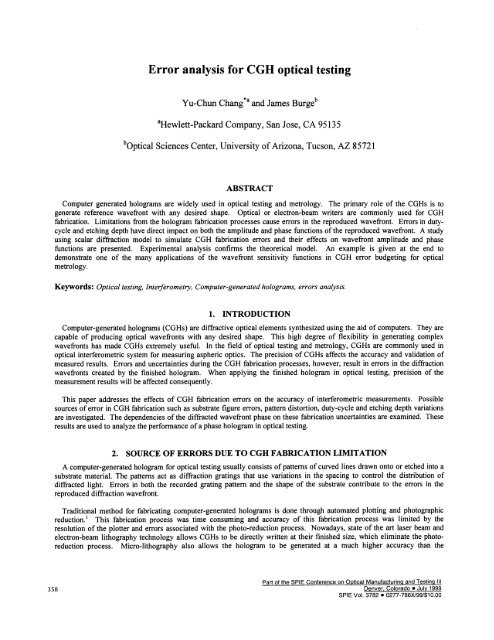
Error analysis for CGH optical testing<br />
Yu-Chun <strong>Chang</strong>*a d James Burgeb<br />
aHewleftpackard Company, San Jose, CA 95135<br />
bOptical Sciences Center, University of Arizona, Tucson, AZ 85721<br />
ABSTRACT<br />
Computer generated holograms are widely used in optical testing <strong>and</strong> metrology. The primary role of the CGHs is to<br />
generate reference wavefront with any desired shape. Optical or electron-beam writers are commonly used for CGH<br />
fabrication. Limitations from the hologram fabrication processes cause errors in the reproduced wavefront. Errors in dutycycle<br />
<strong>and</strong> etching depth have direct impact on both the amplitude <strong>and</strong> phase functions of the reproduced wavefront. A study<br />
using scalar diffraction model to simulate CGH fabrication errors <strong>and</strong> their effects on wavefront amplitude <strong>and</strong> phase<br />
functions are presented. Experimental analysis confirms the theoretical model. An example is given at the end to<br />
demonstrate one of the many applications of the wavefront sensitivity functions in CGH error budgeting for optical<br />
metrology.<br />
Keywords: Optical testing, Interferometry, Computer-generated holograms, errors analysis.<br />
1. INTRODUCTION<br />
Computer-generated holograms (CGHs) are diffractive optical elements synthesized using the aid of computers. They are<br />
capable of producing optical wavefronts with any desired shape. This high degree of flexibility in generating complex<br />
wavefronts has made CGHs extremely useful. In the field of optical testing <strong>and</strong> metrology, CGHs are commonly used in<br />
optical interferometric system for measuring aspheric optics. The precision of CGHs affects the accuracy <strong>and</strong> validation of<br />
measured results. Errors <strong>and</strong> uncertainties during the CGH fabrication processes, however, result in errors in the diffraction<br />
wavefronts created by the finished hologram. When applying the finished hologram in optical testing, precision of the<br />
measurement results will be affected consequently.<br />
This paper addresses the effects of CGH fabrication errors on the accuracy of interferometric measurements. Possible<br />
sources of error in CGH. fabrication such as substrate figure errors, pattern distortion, duty-cycle <strong>and</strong> etching depth variations<br />
are investigated. The dependencies of the diffracted wavefront phase on these fabrication uncertainties are examined. These<br />
results are used to analyze the performance of a phase hologram in optical testing.<br />
2. SOURCE OF ERRORS DUE TO CGH FABRICATION LIMITATION<br />
A computer-generated hologram for optical testing usually consists of patterns of curved lines drawn onto or etched into a<br />
substrate material. The patterns act as diffraction gratings that use variations in the spacing to control the distribution of<br />
diffracted light. Errors in both the recorded grating pattern <strong>and</strong> the shape of the substrate contribute to the errors in the<br />
reproduced diffraction wavefront.<br />
Traditional method for fabricating computer-generated holograms is done through automated plotting <strong>and</strong> photographic<br />
reduction.' This fabrication process was time consuming <strong>and</strong> accuracy of this fabrication process was limited by the<br />
resolution of the plotter <strong>and</strong> errors associated with the photo-reduction process. Nowadays, state of the art laser beam <strong>and</strong><br />
electron-beam lithography technology allows CGHs to be directly written at their finished size, which eliminate the photoreduction<br />
process. Micro-lithography also allows the hologram to be generated at a much higher accuracy than the<br />
Part of the <strong>SPIE</strong> Conference on Optical Manufacturing <strong>and</strong> Testq lit<br />
358 Denver, Colorado • July 1999<br />
<strong>SPIE</strong> Vol. 3782 . 0277-786X/99/$1O.OO
conventional photo-reproduction process. This fabrication method has made it possible to manufacture holograms with high<br />
precision <strong>and</strong> finesse.<br />
CGH fabrication errors may be classified into two basic types: substrate figure errors <strong>and</strong> pattern errors. Pattern errors<br />
may further be classified as fringe position errors, fringe duty-cycle errors <strong>and</strong> fringe etching depth errors. These CGH<br />
fabrication errors will be discussed in detail in the following sections.<br />
3. ERROR ANALYSIS FOR CGHS<br />
The simplest form of a hologram is a linear diffraction grating, where the spatial frequency of the grating pattern is<br />
constant over the entire hologram. A computer-generated hologram with variable fringe spacing may be viewed as a<br />
collection of linear gratings with variable spatial frequency. By controlling the spatial frequencies of these linear gratings<br />
across the CGH, incident light can be deflected into any desired form.2 The performance of a CGH may, therefore, be<br />
directly related to the diffraction characteristics of a linear grating. Linear gratings are often used for studies on CGH<br />
properties in order to avoid mathematical difficulties in modeling complex hologram fringe patterns. To reduce the degree of<br />
complexity of our study, linear gratings are also chosen as the model for our work.<br />
3.1. Binary Linear Grating Model<br />
The linear grating model used in our studies is assumed to have binary amplitude <strong>and</strong> phase distributions. A binary linear<br />
grating has a surface relief profile that may be described as an infinite train of rectangular pulses with a uniform width. The<br />
wavelength of the incident light is assumed to be much smaller than to the grating period (5), so the scalar diffraction<br />
approximations can be applied.3 For a planar wavefront at normal incidence, the output wavefront immediately past the<br />
grating, either reflected or transmitted, can be expressed as a simple product of the incident wavefront function <strong>and</strong> the<br />
grating surface profile function. The output wavefront function can be written as:<br />
u(x) = A0 + (A1e'<br />
—<br />
Ao)rect)*icomb[J<br />
(1)<br />
where A0 <strong>and</strong> A1 correspond to the amplitude values of the output wavefront from the peaks <strong>and</strong> valleys of the grating,<br />
respectively. The values of A0 <strong>and</strong> A1 are determined from the amplitude functions of the reflectance or the transmittance<br />
coefficients at the grating interface using Fresnel equations. The phase function, 4, represents the phase difference between<br />
rays from the peaks <strong>and</strong> rays from the valleys of the grating structure. The form of the output wavefront function (Fig. 1)<br />
resembles the shape of the grating profile.<br />
A1e<br />
:<br />
Aoj<br />
F<br />
Fig. 1<br />
__<br />
K<br />
S<br />
__<br />
1<br />
>x<br />
Output complex wavefront function at the diffraction grating.<br />
In this study, we are mostly interested in the behaviors of the diffraction wavefront in the far-field regime. The far-field<br />
diffraction wavefront is related to the original wavefront via a simply Fourier transform relationship based on the Fraunhofer<br />
diffraction theory. Hence, the far-field wavefront function of a normal incident plane wavefront upon the grating described<br />
in Eq. (1) is:<br />
U() = Z{u(x)} (2)<br />
U() =A0()+ (A1e' — A0). b• sin c(b) comb(S) (3)<br />
= A0ö() + (A1e — A0). D S• sin c(DS) comb(S)<br />
359
{ A0 + [A, cos() — A0]. D }+ i{ A1 sin(). D }; m = 0<br />
{ [A, cos()—A0J.D.sinc(mD) }+i{ A1 sin().D.sinc(mD)}; m =<br />
where = <strong>and</strong> the duty-cycle ofthe linear grating is D =-.<br />
Xz<br />
S<br />
Eq. (3) shows that the diffraction wavefront function U() has non-zero values only when takes values of multiples integer<br />
of 1/S. This behavior describes the existence of multiple diffractive orders.<br />
3.1.1. Diffraction efficiency<br />
Diffraction efficiency (ii) of a hologram is defined as the ratio of the intensity values of the diffracted wavefront to the<br />
intensity of the incident wavefront,<br />
11= 2 (4)<br />
Diffraction efficiency for all orders are computed by evaluating the intensity values at the particular diffraction orders using<br />
Eq. (3). Hence<br />
m=0<br />
11m0 =A- D)2 + AD2 + 2A0A1D(1 - D)cos()<br />
(5)<br />
m =<br />
[A + A — 2A0A1 cos()}D2 sin c2 (mD)<br />
(6)<br />
3.1.2. Wavefront phase<br />
Diffraction wavefront phase function can also be retrieved from Eq. (3). The diffraction wavefront phase function, P, is<br />
determined as:<br />
tan(P)= Im{U()} (7)<br />
Re{U()}<br />
For different diffraction orders, the phase functions are:<br />
m=0<br />
—<br />
DA1 sin() (8)<br />
A0(1 — D)+ A1Dcos(4)<br />
m =<br />
tan('P)<br />
— 5ifl() sin c(mD)<br />
—<br />
[A0 + A1 cos()}. sin c(mD)<br />
The phase value can be obtained by taking the arctangent of these equations.<br />
360
Notice that the sinc(mD) functions are left in both the numerator <strong>and</strong> denominator of Eq. (9); they are needed to preserve<br />
the sign information for the phase unwrapping process. The phase unwrapping process uses the sign information of the real<br />
<strong>and</strong> the imaginary parts of the complex wavefront, U(), to allow calculation of phase in a 0 to 2it period. The new phase<br />
values are then evaluated point by point. Any integer multiple of 2it can be added or subtracted from the phase value to force<br />
the phase function to be continuous.<br />
3.1.3. Phase sensitivity to duty-cycle<br />
We have shown that diffracted wavefront phase can be expressed as a function of duty-cycle <strong>and</strong> phase depth. By taking<br />
the first order derivative of Eqs. (8) <strong>and</strong> (9) with respect to either duty-cycle or phase depth, the phase deviations due to<br />
variations in duty-cycle or phase depth are determined. These deviations are defined as the "wavefront sensitivity functions".<br />
Eqs. (10) <strong>and</strong> (1 1) show the wavefront sensitivity functions that resulted from one unit variation in the grating duty-cycle.<br />
m =0:<br />
m =<br />
&+!In=o _ A0A1sin (10)<br />
ÔD AD2 +A(1—D)2 +2A0A1D(1—D)cos<br />
J for sinc(mD)=0 (11)<br />
aD 0, otherwise<br />
Notice that duty-cycle errors produce wavefront phase errors only in the zero-order diffraction beam. Diffraction wavefront<br />
phase is not sensitive to CGH duty-cycle errors at non-zero diffraction orders.<br />
3.1.4. Phase sensitivity to etch depth<br />
Diffraction wavefront phase sensitivities to CGH etching depth variations at different diffraction orders are also<br />
determined from Eq. (8) <strong>and</strong> (9). Eq. (12) <strong>and</strong> (13) give the zero-order <strong>and</strong> the non-zero order wavefront sensitivity functions<br />
in terms of phase depth variations.<br />
m =0:<br />
m=O<br />
1<br />
.ôtan()m=o<br />
ô4 1 + [tan('P)10 J2 at<br />
— AD2 + A0A1D(1 — D)cos<br />
AD2 + A( — D)2 2A0A1D(1 — D)cos<br />
(12)<br />
m =<br />
34 1+<br />
1<br />
A—A0A1cos<br />
A + A — 2A0A1cos<br />
(13)<br />
The wavefront sensitivity functions (Eq. (10) through (13)) provide a means of calculating the phase changes in the<br />
wavefront that result from duty-cycle or phase depth variations. They can be used to identify hologram structures, which are<br />
361
the most or the least sensitive to duty-cycle <strong>and</strong> phase depth fabrication uncertainties. The information may also be used to<br />
estimate error budgets for applications using CGHs.<br />
3.1.5. Pattern Distortion<br />
The displacement of the recorded fringe in a CGH from its ideal position is commonly referred to as pattern distortion.<br />
The amount of wavefront phase errors produced by the CGH pattern distortions can be expressed as a product of the gradient<br />
ofthe diffracted wavefront function <strong>and</strong> the pattern distortion vector E(x,y) :<br />
zW(x, y) = —VW(x, y) • E(x,y) (14)<br />
where:<br />
AW(x, y) = wavefront phase error;<br />
wx(x,y) = diffraction wavefront;<br />
vwx(x, y) = gradient ofthe diffraction wavefront (in the direction that is perpendicular to the fringes);<br />
E(x, y) = CGH pattern distortion vector.<br />
Therefore, for a linear grating, wavefront phase errors produced by grating pattern distortions in the mth order beam can be<br />
calculated as:<br />
z\W(x,y) = —mX c(x,y) (15)<br />
S(x,y)<br />
where:<br />
(x,y) grating position error in direction perpendicular to the fringes;<br />
S(x,y) — localized fringe spacing;<br />
The produced wavefront phase errors due to pattern distortions are linearly proportional to the diffraction order number<br />
<strong>and</strong> inversely proportional to the local fringe spacing. Furthermore, CGH pattern distortion errors do not affect the zeroorder<br />
diffracted beam.<br />
3.2. CGH Substrate Errors<br />
Typical CGH substrate errors are low spatial frequency surface figure errors that are responsible for the low spatial<br />
frequency wavefront aberrations in the diffracted wavefront. Fig. 2 gives a simple demonstration. For instance, in a<br />
reflection hologram setup, a surface defect on a CGH substrate with a peak-to-valley deviation of & will produce a phase<br />
error in the reflected wavefront that equals 2ös because of the double path configuration. A transmission hologram that has<br />
the same peak-to-valley surface defect, on the other h<strong>and</strong>, will produce a wavefront phase error that is (n- l)s, where n is the<br />
index of refraction of the substrate material.<br />
One method of eliminating figure errors in a CGH is to measure the flatness of the substrate before the grating patterns are<br />
applied. This procedure is usually done using a Fizeau interferometer with a flat reference.<br />
362
[NCIDENT<br />
WAVEFRONT<br />
CGH SUBSTRATE<br />
(n = INDEX OF REFRACTION)<br />
REFLECTED<br />
WAVEFRONT<br />
TRANSMITTED<br />
WAVEFRONT<br />
(n-1)&<br />
Fig. 2 Wavefront deviations due to substrate surface defects for both reflective <strong>and</strong> transmissive type holograms.<br />
4. EXPERIMENTAL ANALYSIS<br />
To validate the diffraction model, two custom holograms were fabricated: one is phase hologram <strong>and</strong> the other is chromeon-glass<br />
hologram. The phase hologram was designed with duty-cycle <strong>and</strong> etching depths varied across hologram <strong>and</strong> the<br />
chrome-on-glass hologram was designed with only varied duty-cycle values. Both holograms were measured using phaseshifting<br />
interferometers. The results of phase sensitivity measurements for both holograms were compared with theoretical<br />
models. The experimental data agree with the theoretical analysis.6 Fig. 3 illustrates an interferogram for the zero-order<br />
phase hologram.<br />
4(* 5S<br />
O22<br />
024?.<br />
(h25.<br />
o2Th<br />
Fig. 3 Interferograrnc d for the sample phase hologram shown in the zero-order.<br />
(Note the phase shift around the center of the pattern).<br />
363
5. ERRORS ANALYSIS OF A PHASE CGH<br />
When applying CGHs in optical testing, it is necessary to evaluate the CGH in order to assure the validation <strong>and</strong> accuracy<br />
of the measured results. An example of a phase CGH incorporated with a Fizeau interferometer for testing aspheric optical<br />
components is shown in Fig. 4.<br />
FIZEAU INTERFEROMETER<br />
SPHERICAL<br />
REFERENC<br />
__7•• .<br />
PHASE CGH<br />
I—i<br />
.. . .<br />
... .. .<br />
ASPHERE TEST<br />
PIECE<br />
Fig. 4 Asphere metrology uses a Fizeau interferometer with a phase CGH.<br />
In this example, typical values of phase CGH parameters are assigned. The example phase CGH is designed to be used in<br />
the order transmission mode. The hologram is made by a glass substrate with an index ofrefraction of 1.5. It has a grating<br />
groove depth of rt radians <strong>and</strong> a 50% duty-cycle. A potential pattern distortion of lum is assumed. The averaged fringe<br />
spacing on the CGH is approximately 40 urn. The phase CGH has a RMS substrate figure error of 2JIO on both the front <strong>and</strong><br />
the back surface.<br />
To determine wavefront phase deviations caused by CGH fabrication errors, wavefront phase errors analysis results<br />
obtained in the previous section are employed. It should be obvious that surface figure errors from both the front <strong>and</strong> the<br />
back surface of the CGH contribute to aberrations in the diffracted wavefront, since the hologram is used in the transmission<br />
mode. The errors contributed by each surface is 2/2O. The effect of pattern distortion to diffracted phase is proportional to<br />
the diffraction order number <strong>and</strong> inversely proportional to the grating spacing of A140 (Eq. 15). The first order wavefront<br />
phase deviations due to duty-cycle <strong>and</strong> grating groove depth errors are determined using wavefront sensitivity functions, Eqs<br />
(1 1) <strong>and</strong> (13). Duty-cycle deviations have no effects on the wavefront phase since the hologram is operated at its 1st<br />
diffraction order. A variation of five percent in phase depth would generate a Ai80 wavefront phase change. Since the test<br />
beam passes through the CGH twice in this setup, the total wavefront phase error for the setup is twice the value of the<br />
calculated error per pass. The calculated wavefront phase errors per pass for each error source are listed below:<br />
Table 1 Diffraction wavefront phase errors from CGH fabrication uncertainties.<br />
<strong>Fabrication</strong> Wavefront Phase<br />
Source of Errors<br />
Tolerances Errors per Pass<br />
RMS Substrate Fig. Error (Front<br />
X/20<br />
Surface)<br />
RMS Substrate Fig. Error (Back<br />
X/l<br />
/2O<br />
Surface)<br />
Pattern Distortion<br />
urn<br />
Grating Groove Depth Error<br />
Duty-cycle Error 0<br />
Root-Sum-Squared Errors:<br />
Assuming the calculated CGH errors are un-correlated to each other, the total wavefront phase errors for the phase<br />
hologram can be estimated as the root-sum-square (RSS) of these errors. The calculation shows that the estimated diffracted<br />
wavefront phase errors produced by fabrication uncertainties <strong>and</strong> tolerance in the phase CGH is approximately<br />
0. l52? including the effect of the double path of the test beam. In other words, the accuracy of the aspheric measurement<br />
364
using the setup in Fig. 3 <strong>and</strong> the example CGH is limited by<br />
interferometer errors <strong>and</strong> air turbulence, are eliminated.<br />
even when other sources of errors, such as<br />
As shown in Table 1, the largest individual error source is the substrate figure errors of the CGH. Normally the substrate<br />
error may be identified <strong>and</strong> eliminated. CGH substrate errors can be measured using the zero-order diffraction beam. In this<br />
example, however, the phase grating is constructed by a 50% duty-cycle <strong>and</strong>/2 phase depth. The zero-order diffracted<br />
wavefront phase has extremely high sensitivities to duty-cycle variations for a grating with a 50%duty-cycle <strong>and</strong>?J2 phase<br />
depth (see Fig. 5). In other words, a 1% duty-cycle fabrication error on the grating could produce up to2J2 wavefront phase<br />
deviations. This phase error overwhelms the effects of the CGH substrate error in the zero diffraction order <strong>and</strong> prohibits the<br />
substrate figure measurement in this example.<br />
3<br />
-c<br />
a.<br />
0)<br />
wp-I<br />
(flu)<br />
(50)<br />
.c><br />
a. cs<br />
0)<br />
(1)0)<br />
(5><br />
0<br />
0<br />
2<br />
-2<br />
0 0.1 0.2 0.3 0.4 0.5 0.6 0.7 0.8 0.9 1<br />
phase depth [waves]<br />
Fig. 5 Wavefront phase sensitivity of phase grating to grating phase depth variation<br />
for the zero-order beam for various duty-cycle values.<br />
365
6. CONCLUSIONS<br />
In this paper, we have studied CGH fabrication errors <strong>and</strong> their impacts on diffraction wavefronts. Theoretical modeling<br />
of CGHs with fringe duty-cycle <strong>and</strong> etch depth variations are presented. Analytical solutions are obtained <strong>and</strong> are<br />
summarized in the table below.<br />
Table 2 Summary of equations for diffraction analysis.<br />
Zero order (m = 0) Non-zero order (m<br />
1 AD(1 — D)2 + AD2 + 24A1D(1 — D)cos(Ø) [ui +A — 24A1 cos(q$)}D2 sinc2(mD)<br />
. A0A1<br />
tan(kP) A1D sin(Ø) A1 sin(Ø) .siir (mD)<br />
A0 (1 — D) + A1 D cos(çb)<br />
[—A0 + A1 cos(q$)] . siir (mD)<br />
sin 0 1 for sinc(mD) = 0<br />
!<br />
dD AD2 + A(1 — D)2 + 2A0A1D(1 — D)cosØ 0, otherwise<br />
AD2 + A0A1D(1 — D)cosq$ A — A0A1 cosçb<br />
dq5 AD2 + A (1 —D)2 + 2A0A1D(1 — D)cosq$ A +A — 2AØAJ cos q$<br />
The theoretical results are validated by experimental data. Applications of wavefront sensitivity functions in optical<br />
testing are demonstrated. The introduction of the wavefront sensitivity functions provides a quick <strong>and</strong> more intuitive method<br />
of CGH error analysis <strong>and</strong> error budgeting. The results of this research provide guidance to tolerance analysis of CGHs in<br />
the field of optical testing. They may also be used to direct CGH designs that will reduce or eliminate effects from<br />
fabrication errors.<br />
ACKNOWLEDGMENTS<br />
This work has been supported in part by the Eastman Kodak Company project number: 98Z90003 1461.<br />
REFERENCES<br />
1<br />
Lohmann, A.W. <strong>and</strong> D. P. Paris, " BinaryFraunhofer holograms, generated by computer," Appl. Opt., 6, 1739-1748<br />
(1967).<br />
2 Burge, J. H. "Applications of computer-generated holograms for interferometric measurement of large aspheric optics,"<br />
<strong>Proc</strong>. <strong>SPIE</strong>, 2576, 258-269 (1995).<br />
Goodman, J. W., Introduction to Fourier <strong>Optics</strong> 2" Ed., McGraw-Hill, Inc., N.Y., 1996.<br />
.<br />
Born, M. <strong>and</strong> E. Wolf, Principles of <strong>Optics</strong> 61h Ed., Cambridge University Press, N.Y., 1980.<br />
Fercher, A. F. "Computer-generated holograms for testing optical elements: error analysis <strong>and</strong> error compensation,"<br />
Optica Acta, 23, 347-365 (1976).<br />
6<br />
<strong>Chang</strong>, Y. C. "Diffraction wavefront analysis of computer-generated holograms," Ph.D. dissertation, Optical Sciences<br />
Center, University of Arizona, 1999.<br />
366