Meraki Cloud Controller Product Manual - Cloud Distribution
Meraki Cloud Controller Product Manual - Cloud Distribution
Meraki Cloud Controller Product Manual - Cloud Distribution

Create successful ePaper yourself
Turn your PDF publications into a flip-book with our unique Google optimized e-Paper software.
<strong>Meraki</strong> <strong>Cloud</strong> <strong>Controller</strong><br />
<strong>Product</strong> <strong>Manual</strong><br />
May 2011<br />
®<br />
Copyright © 2011, <strong>Meraki</strong>, Inc.
®<br />
www.meraki.com<br />
660 Alabama St.<br />
San Francisco, California 94110<br />
Phone: +1 415 632 5800<br />
Fax: +1 415 632 5899<br />
Copyright: © 2011 <strong>Meraki</strong>, Inc. All rights reserved.<br />
Trademarks: <strong>Meraki</strong>® is a registered trademark of <strong>Meraki</strong>, Inc.<br />
<strong>Meraki</strong> <strong>Cloud</strong> <strong>Controller</strong> <strong>Product</strong> <strong>Manual</strong> | 2
Table of Contents<br />
1 Introduction ............................................................................................................. 10 <br />
1.1 Primary MCC Functions ..................................................................................................................... 10 <br />
1.2 MCC Versions .................................................................................................................................... 10 <br />
1.3 MCC Layout ....................................................................................................................................... 11 <br />
1.4 How to Use This Document ................................................................................................................ 11 <br />
2 System Overview .................................................................................................... 13 <br />
2.1 Data Flow ........................................................................................................................................... 14 <br />
2.2 Centralized Management and Monitoring .......................................................................................... 14 <br />
2.3 Security .............................................................................................................................................. 14 <br />
2.4 Network Optimization ......................................................................................................................... 14 <br />
2.5 Availability .......................................................................................................................................... 14 <br />
2.6 Mesh Networking ................................................................................................................................ 15 <br />
2.7 Over-the-Air Upgrades ....................................................................................................................... 15 <br />
3 Getting Started ........................................................................................................ 16 <br />
4 Configuring SSIDs .................................................................................................. 17 <br />
5 Assigning IP Addresses to Wireless Clients ........................................................ 18 <br />
5.1 NAT Mode .......................................................................................................................................... 18 <br />
5.2 Bridge Mode (Enterprise Only) ........................................................................................................... 18 <br />
5.3 VPNs .................................................................................................................................................. 19 <br />
6 Configuring the LAN ............................................................................................... 20 <br />
6.1 Firewall Settings ................................................................................................................................. 20 <br />
6.2 Assigning IP Addresses to <strong>Meraki</strong> APs .............................................................................................. 20 <br />
6.2.1 Configuring a Static IP Address Directly on a <strong>Meraki</strong> AP ................................................................ 20 <br />
6.2.2 Configuring a Static IP Address for a <strong>Meraki</strong> AP via DHCP Reservations ...................................... 21 <br />
7 Wireless Encryption and Authentication .............................................................. 22 <br />
7.1 Association Requirements .................................................................................................................. 22 <br />
7.1.1 Open ................................................................................................................................................ 23 <br />
7.1.2 MAC-Based Access Control (Enterprise Only) ................................................................................ 23 <br />
7.1.3 Pre-Shared Keys (WEP, WPA/WPA2-Personal) ............................................................................. 23 <br />
7.1.4 WPA2-Enterprise with 802.1x Authentication (Enterprise Only) ..................................................... 24 <br />
7.2 Network Sign-On Methods ................................................................................................................. 24 <br />
<strong>Meraki</strong> <strong>Cloud</strong> <strong>Controller</strong> <strong>Product</strong> <strong>Manual</strong> | 3
7.2.1 Direct Access .................................................................................................................................. 25 <br />
7.2.2 Click-Through Splash Page ............................................................................................................. 25 <br />
7.2.3 Sign-On Splash Page ...................................................................................................................... 25 <br />
7.2.4 Billing ............................................................................................................................................... 26 <br />
7.2.5 Hosting Your Own Splash Page ...................................................................................................... 26 <br />
7.3 Configuring an Authentication Server ................................................................................................. 26 <br />
7.3.1 <strong>Meraki</strong>-Hosted Authentication Server .............................................................................................. 26 <br />
7.3.2 Externally Hosted RADIUS Server .................................................................................................. 27 <br />
8 Monitoring ................................................................................................................ 33 <br />
8.1 Overview Page ................................................................................................................................... 33 <br />
8.2 All-Network Overview Page ................................................................................................................ 34 <br />
8.3 Maps Page (Enterprise Only) ............................................................................................................. 34 <br />
8.4 Access Points Page ........................................................................................................................... 35 <br />
8.5 Access Point Details Page ................................................................................................................. 36 <br />
8.5.1 AP Tagging ...................................................................................................................................... 37 <br />
8.6 Clients Page ....................................................................................................................................... 39 <br />
8.6.1 Clients Overview Page Features ..................................................................................................... 39 <br />
8.6.2 Traffic Analysis (Enterprise Only) .................................................................................................... 40 <br />
8.6.3 Client Details Page .......................................................................................................................... 41 <br />
8.6.4 Client Location Services .................................................................................................................. 43 <br />
8.7 Event Log Page (Enterprise Only) ...................................................................................................... 44 <br />
8.8 Rogue APs Page (Enterprise Only) .................................................................................................... 45 <br />
8.9 Summary Report Page (Enterprise Only) ........................................................................................... 45 <br />
8.10 Live Updates (Enterprise Only) ......................................................................................................... 45 <br />
8.11 Search Tool ....................................................................................................................................... 46 <br />
8.12 Email Alerts ....................................................................................................................................... 46 <br />
8.13 Export XML Data ............................................................................................................................... 46 <br />
8.14 Logins Page ...................................................................................................................................... 46 <br />
8.15 Account Activity Page ........................................................................................................................ 47 <br />
9 VLAN Tagging (Enterprise Only) ........................................................................... 48 <br />
9.1 Per-SSID VLAN Tagging .................................................................................................................... 49 <br />
9.2 Per-User VLAN Tagging ..................................................................................................................... 49 <br />
9.3 Management Traffic ........................................................................................................................... 49 <br />
9.4 Configuring the LAN to Support VLAN Tagging ................................................................................. 50 <br />
9.5 Other Considerations ......................................................................................................................... 50 <br />
<strong>Meraki</strong> <strong>Cloud</strong> <strong>Controller</strong> <strong>Product</strong> <strong>Manual</strong> | 4
10 User Access Control Features .............................................................................. 51 <br />
10.1 Network Access Control .................................................................................................................... 51 <br />
10.2 MAC Whitelist .................................................................................................................................... 52 <br />
10.3 MAC Blacklist .................................................................................................................................... 52 <br />
10.4 Bandwidth Shaping ........................................................................................................................... 53 <br />
10.5 Adult Content Filtering ....................................................................................................................... 53 <br />
10.6 Firewall Rules for Wireless Users ...................................................................................................... 54 <br />
10.6.1 LAN Isolation ................................................................................................................................. 54 <br />
10.6.2 Custom Firewall Rules (Enterprise Only) ...................................................................................... 54 <br />
10.7 Captive Portal Strength ..................................................................................................................... 55 <br />
10.8 Enable/Disable Simultaneous Logins ................................................................................................ 55 <br />
10.9 Walled Garden (Enterprise Only) ...................................................................................................... 55 <br />
11 Identity Policy Manager (Enterprise Only) ........................................................... 57 <br />
11.1 How IPM Works ................................................................................................................................. 57 <br />
11.2 How to Configure IPM ....................................................................................................................... 58 <br />
11.2.1 Define a Group Policy on the RADIUS Server .............................................................................. 58 <br />
11.2.2 Define a Group Policy on the MCC ............................................................................................... 58 <br />
11.2.3 Test the IPM Configuration ............................................................................................................ 60 <br />
12 Traffic Shaper (Enterprise Only) ........................................................................... 61 <br />
12.1 Configuring Shaping Policies ............................................................................................................ 61 <br />
12.1.1 Creating Shaping Rules ................................................................................................................ 61 <br />
12.1.2 Example Shaping Policy ................................................................................................................ 62 <br />
13 Guest Management (Enterprise Only) .................................................................. 63 <br />
14 Rogue AP Detection (Enterprise Only) ................................................................. 64 <br />
15 Wireless Features ................................................................................................... 66 <br />
15.1 AutoRF .............................................................................................................................................. 66 <br />
15.2 Channel Selection ............................................................................................................................. 66 <br />
15.3 Channel Spreading (Enterprise Only) ............................................................................................... 67 <br />
15.4 Network Scans (Enterprise Only) ...................................................................................................... 67 <br />
15.5 Spectrum Analysis (Enterprise Only) ................................................................................................ 67 <br />
15.6 Transmit Power Control (Enterprise Only) ......................................................................................... 68 <br />
15.7 Radio Settings Page (Enterprise Only) ............................................................................................. 68 <br />
15.7.1 Radio Controls ............................................................................................................................... 68 <br />
15.7.2 Channel Planning Report .............................................................................................................. 68 <br />
<strong>Meraki</strong> <strong>Cloud</strong> <strong>Controller</strong> <strong>Product</strong> <strong>Manual</strong> | 5
15.8 SSID Availability Page ....................................................................................................................... 68 <br />
15.8.1 SSID Visibility (Enterprise Only) .................................................................................................... 68 <br />
15.8.2 SSID Broadcast Controls By AP (Enterprise Only) ....................................................................... 69 <br />
15.8.3 Timed SSID Broadcasting (Enterprise Only) ................................................................................. 70 <br />
15.9 Band Selection and Band Steering (Enterprise Only) ....................................................................... 70 <br />
15.10 Disabling Legacy 802.11b Bitrates (Enterprise Only) ........................................................................ 70 <br />
15.11 Software Upgrades ............................................................................................................................ 71 <br />
15.11.1 Preferred Maintenance Window (Enterprise Only) ...................................................................... 71 <br />
15.12 Mesh Networking ............................................................................................................................... 71 <br />
15.13 Wired Clients ..................................................................................................................................... 72 <br />
15.14 Wireless Bridging ............................................................................................................................... 72 <br />
15.15 Quality of Service .............................................................................................................................. 72 <br />
15.16 Power Save ....................................................................................................................................... 73 <br />
15.17 Run Dark ........................................................................................................................................... 73 <br />
15.18 Accessing the AP’s Local Web Page ................................................................................................ 73 <br />
16 Branding .................................................................................................................. 74 <br />
16.1 Splash Page ...................................................................................................................................... 74 <br />
16.1.1 <strong>Meraki</strong>-Hosted Splash Page .......................................................................................................... 74 <br />
16.1.2 Externally Hosted Splash Page ..................................................................................................... 74 <br />
16.1.3 Splash Page Frequency ................................................................................................................ 74 <br />
16.2 Toolbar .............................................................................................................................................. 75 <br />
17 Billing ....................................................................................................................... 76 <br />
18 Administering Multiple Networks .......................................................................... 77 <br />
18.1 Organizations .................................................................................................................................... 77 <br />
18.2 Administrators .................................................................................................................................... 77 <br />
18.2.1 Organization Administrators .......................................................................................................... 77 <br />
18.2.2 Network Administrators ................................................................................................................. 78 <br />
18.3 Moving APs between Networks or Organizations ............................................................................. 78 <br />
19 Teleworker VPN ...................................................................................................... 79 <br />
19.1 Typical Use Cases ............................................................................................................................. 79 <br />
19.2 How It Works ..................................................................................................................................... 79 <br />
19.3 The Virtual Concentrator ................................................................................................................... 79 <br />
19.4 Creating the Virtual Concentrator Network ........................................................................................ 80 <br />
19.5 Installing the Virtual Concentrator ..................................................................................................... 80 <br />
<strong>Meraki</strong> <strong>Cloud</strong> <strong>Controller</strong> <strong>Product</strong> <strong>Manual</strong> | 6
19.6 Monitoring the Virtual Concentrator ................................................................................................... 81 <br />
19.6.1 Overview ....................................................................................................................................... 81 <br />
19.6.2 Concentrator Status ...................................................................................................................... 81 <br />
19.6.3 Clients ........................................................................................................................................... 81 <br />
19.6.4 Event Log ...................................................................................................................................... 81 <br />
19.6.5 Summary Report ........................................................................................................................... 81 <br />
19.7 Configuring the Virtual Concentrator ................................................................................................. 82 <br />
19.7.1 Concentrator Settings .................................................................................................................... 82 <br />
19.7.2 Alerts and Administrators .............................................................................................................. 82 <br />
19.8 Configuring Remote APs ................................................................................................................... 82 <br />
19.9 Create Remote Site Network and Add APs ....................................................................................... 83 <br />
19.9.1 Configure SSIDs to Tunnel ............................................................................................................ 83 <br />
19.9.2 Tunneling wired client traffic .......................................................................................................... 83 <br />
19.10 Configuration Best Practices ............................................................................................................. 84 <br />
19.10.1 Concentrator Location(s) ............................................................................................................. 84 <br />
19.10.2 Firewall Settings .......................................................................................................................... 84 <br />
20 Licensing ................................................................................................................. 86 <br />
20.1 Adding Licenses ................................................................................................................................ 86 <br />
20.2 <strong>Cloud</strong> <strong>Controller</strong> Upgrades ................................................................................................................ 87 <br />
20.3 Renewing Licenses ........................................................................................................................... 87 <br />
20.4 Expired Licenses or Exceeding the Licensed AP Limit ..................................................................... 87 <br />
21 Troubleshooting ..................................................................................................... 88 <br />
22 References .............................................................................................................. 89 <br />
23 Appendix A: Example Office Configuration ......................................................... 90 <br />
23.1 Objectives .......................................................................................................................................... 90 <br />
23.2 Implementation Alternatives .............................................................................................................. 91 <br />
23.3 Assumptions ...................................................................................................................................... 91 <br />
23.4 Configuration for Guests ................................................................................................................... 92 <br />
23.4.1 Configuration Settings ................................................................................................................... 92 <br />
23.4.2 Configure a Splash Page .............................................................................................................. 92 <br />
23.4.3 Create a Guest Ambassador ......................................................................................................... 93 <br />
23.5 Configuration for Employees ............................................................................................................. 94 <br />
23.5.1 Dashboard Configuration .............................................................................................................. 94 <br />
23.5.2 Configure <strong>Meraki</strong> APs as RADIUS Clients in NPS ........................................................................ 95 <br />
<strong>Meraki</strong> <strong>Cloud</strong> <strong>Controller</strong> <strong>Product</strong> <strong>Manual</strong> | 7
23.5.3 Testing RADIUS Authentication .................................................................................................... 96 <br />
23.6 Configuration for Contractors ............................................................................................................ 97 <br />
23.6.1 Configuration for Users ................................................................................................................. 97 <br />
23.6.2 Configuration of NPS Policies ....................................................................................................... 99 <br />
23.6.3 Configuration of Group Policy in the <strong>Meraki</strong> <strong>Cloud</strong> <strong>Controller</strong> ..................................................... 102 <br />
23.6.4 Testing the Group Policy Application .......................................................................................... 103 <br />
23.7 Traffic Shaping Configuration .......................................................................................................... 104 <br />
23.8 Summary ......................................................................................................................................... 105 <br />
24 Appendix B: Example Teleworker VPN Configuration ...................................... 106 <br />
24.1 Objectives ........................................................................................................................................ 106 <br />
24.2 Virtual Concentrator Installation ...................................................................................................... 107 <br />
24.2.1 Virtual Concentrator Network ...................................................................................................... 107 <br />
24.2.2 Virtual Concentrator Configuration Settings ................................................................................ 108 <br />
24.2.3 Installing the Virtual Concentrator in VMware ............................................................................. 109 <br />
24.3 Remote Site Network Configuration ................................................................................................ 110 <br />
24.3.1 Remote Site Network .................................................................................................................. 110 <br />
24.4 AP Pre-Configuration ...................................................................................................................... 112 <br />
25 Appendix B: Miscellaneous Configuration Settings ......................................... 114 <br />
25.1 FreeRADIUS Configuration ............................................................................................................. 114 <br />
25.1.1 Configuration for APs (clients.conf file) ....................................................................................... 114 <br />
25.1.2 Configuration for Users (Users file) ............................................................................................. 114 <br />
25.1.3 Configuration for WPA2-Enterprise with 802.1x Authentication (eap.conf file) ........................... 115 <br />
25.2 Switch Configuration for VLAN Tagging .......................................................................................... 115 <br />
26 Appendix C: RADIUS Attributes .......................................................................... 116 <br />
26.1 Authentication Attributes ................................................................................................................. 116 <br />
26.1.1 Attributes Supported in Access-Request Messages ................................................................... 116 <br />
26.1.2 Attributes Supported in Access-Accept Messages ...................................................................... 116 <br />
26.1.3 Attributes Supported in Access-Reject Messages ...................................................................... 117 <br />
26.2 Accounting Attributes ...................................................................................................................... 118 <br />
27 Appendix D: <strong>Meraki</strong>-Hosted Splash Page Variables ......................................... 119 <br />
<strong>Meraki</strong> <strong>Cloud</strong> <strong>Controller</strong> <strong>Product</strong> <strong>Manual</strong> | 8
<strong>Meraki</strong> <strong>Cloud</strong> <strong>Controller</strong> <strong>Product</strong> <strong>Manual</strong> | 9
1 Introduction<br />
The <strong>Meraki</strong> <strong>Cloud</strong> <strong>Controller</strong> (MCC) provides centralized management,<br />
optimization, and monitoring of a <strong>Meraki</strong> wireless LAN system. The MCC is not<br />
an appliance that an administrator must purchase and install in a data center to<br />
manage wireless access points (APs). Rather, the MCC is a cloud-based service<br />
that is constantly monitoring, optimizing, and reporting on the behavior of the<br />
network.<br />
1.1 Primary MCC Functions<br />
An administrator uses the MCC to configure and monitor <strong>Meraki</strong> wireless<br />
networks. The MCC provides the following primary functions:<br />
• Centralized configuration:<br />
o<br />
o<br />
Configuration of multiple geographically distributed networks.<br />
Secure access to configuration settings via a web browser.<br />
• Network optimization:<br />
o<br />
o<br />
Performance optimization through RF management.<br />
Diagnostic tools to enable proper AP placement.<br />
• Centralized monitoring:<br />
o<br />
o<br />
Usage statistics, login history, and alerts.<br />
Remote troubleshooting and issue diagnosis.<br />
1.2 MCC Versions<br />
There are two versions of the MCC:<br />
• <strong>Meraki</strong> Enterprise <strong>Cloud</strong> <strong>Controller</strong>: The <strong>Meraki</strong> Enterprise <strong>Cloud</strong><br />
<strong>Controller</strong> enables companies and organizations to setup secure<br />
wireless LANs. Examples include offices, warehouses, retail stores,<br />
educational campuses, and healthcare institutions.<br />
• <strong>Meraki</strong> Pro <strong>Cloud</strong> <strong>Controller</strong>: The <strong>Meraki</strong> Pro <strong>Cloud</strong> <strong>Controller</strong> is for<br />
basic wireless deployments that require Internet-only access. Examples<br />
include fee-based wireless hotspots, coffee shops, and other amenity<br />
networks.<br />
This manual addresses all features supported by the <strong>Meraki</strong> Enterprise <strong>Cloud</strong><br />
<strong>Controller</strong> and the <strong>Meraki</strong> Pro <strong>Cloud</strong> <strong>Controller</strong>. Some features in the <strong>Meraki</strong><br />
Enterprise <strong>Cloud</strong> <strong>Controller</strong> are not available in the <strong>Meraki</strong> Pro <strong>Cloud</strong> <strong>Controller</strong>;<br />
these features are designated as “Enterprise Only”.<br />
<strong>Meraki</strong> <strong>Cloud</strong> <strong>Controller</strong> <strong>Product</strong> <strong>Manual</strong> | 10
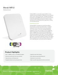
1.3 MCC Layout<br />
Figure 1 is a screenshot of the main page of the <strong>Meraki</strong> Enterprise <strong>Cloud</strong><br />
<strong>Controller</strong>’s administrator interface.<br />
Figure 1 – <strong>Meraki</strong> Enterprise <strong>Cloud</strong> <strong>Controller</strong> Administrator Interface<br />
The 3 tabs in the left navigation panel are as follows:<br />
• Monitor: View information about APs, client devices, and users.<br />
• Configure: Configure the various features of the MCC, such as SSIDs,<br />
authentication, and branding.<br />
• Help: Get access to technical support and the <strong>Meraki</strong> knowledge base.<br />
1.4 How to Use This Document<br />
The chapters in this manual begin with more basic topics and progress to more<br />
advanced topics. The chapters are roughly grouped as follows:<br />
Overview<br />
Chapters 1-2<br />
These chapters provide an introduction to the <strong>Meraki</strong><br />
wireless solution.<br />
Basic Topics<br />
Chapters 3-8<br />
These chapters enable an administrator to get a simple<br />
wireless network up and running. Wireless and<br />
networking fundamentals are reviewed.<br />
<strong>Meraki</strong> <strong>Cloud</strong> <strong>Controller</strong> <strong>Product</strong> <strong>Manual</strong> | 11
Advanced Topics<br />
Chapters 9-17<br />
These chapters describe sophisticated features that<br />
enable administrators to manage and monitor their <strong>Meraki</strong><br />
wireless networks more effectively.<br />
Administrative Topics<br />
Chapters 18-20<br />
These chapters discuss some of features and functions<br />
pertaining to <strong>Meraki</strong> network administrators.<br />
Chapters 21-25<br />
References and Appendices<br />
<strong>Meraki</strong> <strong>Cloud</strong> <strong>Controller</strong> <strong>Product</strong> <strong>Manual</strong> | 12
2 System Overview<br />
This chapter explains how the MCC operates and fits into the overall <strong>Meraki</strong><br />
system.<br />
In the <strong>Meraki</strong> architecture, there is only one type of hardware: access points<br />
(APs). There is no need for specialized hardware controllers or management<br />
appliances. <strong>Meraki</strong> APs tunnel back to the MCC via a secure Internet connection.<br />
All control, configuration, optimization, and mobility control functions are<br />
centralized in <strong>Meraki</strong>’s network operations centers (NOCs), which are distributed<br />
geographically around the world. These NOCs provide physical security to the<br />
MCC, as well as high availability through power backups and redundant servers<br />
in hot standby mode. The geographical distribution of the NOCs also improves<br />
the performance of <strong>Meraki</strong> wireless networks by minimizing the distance that<br />
networks need to travel to contact the MCC.<br />
An administrator can use the MCC to make configuration changes and obtain<br />
reporting information on his networks. For example, the administrator may wish<br />
to change the bandwidth available to guests accessing the network. Once that<br />
change is made through the MCC, all APs automatically receive the new<br />
configuration.<br />
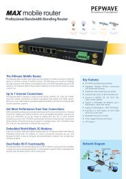
Figure 2 depicts the primary components of a <strong>Meraki</strong> wireless system.<br />
Figure 2 – <strong>Meraki</strong> Wireless System Architecture<br />
<strong>Cloud</strong><br />
<strong>Controller</strong><br />
Internet<br />
Firewall<br />
LAN<br />
AP AP AP AP<br />
Client<br />
<strong>Meraki</strong> <strong>Cloud</strong> <strong>Controller</strong> <strong>Product</strong> <strong>Manual</strong> | 13
2.1 Data Flow<br />
The MCC is “out of band,” which means that client traffic never flows through the<br />
MCC. This architecture is important both for performance as well as security<br />
reasons. It is not possible for an unauthorized person having access to the MCC<br />
to see user data, and the MCC is not a bottleneck for data traffic flows. Thus, the<br />
system operates securely and efficiently.<br />
2.2 Centralized Management and Monitoring<br />
MCC management and monitoring activities are performed remotely through the<br />
<strong>Meraki</strong> Dashboard, the web-based interface to the MCC. Dashboard can be<br />
accessed using any JavaScript-capable Internet web browser, including Firefox,<br />
Internet Explorer, and Chrome. Unlike other solutions, there is no need to install<br />
and maintain separate management servers or appliances. The administrator<br />
can troubleshoot multiple wireless networks remotely from a single interface.<br />
Through the <strong>Meraki</strong> Dashboard, administrators have access to standard<br />
troubleshooting tools, such as ping and throughput tests. In addition,<br />
administrators can monitor bandwidth and usage data, either through the <strong>Meraki</strong><br />
Dashboard or with existing monitoring infrastructure using <strong>Meraki</strong>’s XML-based<br />
API. An administrator can build custom monitoring and reporting applications<br />
based on historical statistics without installing additional software or hardware on<br />
site.<br />
2.3 Security<br />
Control traffic flows between the APs and the MCC via a persistent secure<br />
tunnel. All sensitive data, such as configuration details, user names, and<br />
passwords, are encrypted. In addition, traffic between APs in a <strong>Meraki</strong> network is<br />
encrypted using a per-network Advanced Encryption Standard (AES) key. The<br />
MCC distributes the secret network key over SSL when each AP downloads its<br />
configuration. The in-network encryption is performed with the assistance of<br />
hardware accelerators, and does not cause performance degradation or<br />
increased latency on a per-hop basis. Furthermore, security keys (such as WEP<br />
or WPA2 encryption keys) cannot be retrieved off an access point even if an<br />
attacker has physical possession of the device.<br />
2.4 Network Optimization<br />
The MCC provides round-the-clock optimization of the <strong>Meraki</strong> wireless network.<br />
<strong>Meraki</strong>’s Auto RF optimization capability monitors channel utilization and<br />
interference, ensuring the network is operating at peak performance. The MCC<br />
can minimize channel utilization in any given part of the network by assigning<br />
channels to the individual radios and by adjusting the radio transmit powers.<br />
Mesh routes are also constantly updated to ensure maximum client throughput.<br />
2.5 Availability<br />
Multiple geographically distributed <strong>Meraki</strong> data centers are used to ensure that<br />
networks continue to function even in the event of a catastrophic failure. In case<br />
the MCC is ever unreachable (e.g., because the Internet route to the MCC has<br />
<strong>Meraki</strong> <strong>Cloud</strong> <strong>Controller</strong> <strong>Product</strong> <strong>Manual</strong> | 14
gone down temporarily), <strong>Meraki</strong> networks that do not use the MCC for<br />
authentication or splash page hosting continue to operate, providing wireless<br />
connectivity to users using the last configuration it obtained from the MCC.<br />
Configuration changes and firmware upgrades resume when the MCC is<br />
reachable again.<br />
2.6 Mesh Networking<br />
All <strong>Meraki</strong> APs support mesh networking. A <strong>Meraki</strong> AP automatically configures<br />
as either a mesh gateway or a mesh repeater. A mesh gateway is an AP that<br />
connects directly to a wired network, such as an enterprise LAN or T1 modem. A<br />
mesh repeater does not require a wired connection. Instead, it identifies the<br />
nearest mesh gateway in its network and spreads wireless connectivity from that<br />
mesh gateway over a wider coverage area. A collection of mesh repeaters and<br />
mesh gateways form a wireless mesh network. The data flowing from a client<br />
may go through several mesh repeaters before reaching a mesh gateway, at<br />
which point the data enters the wired network.<br />
2.7 Over-the-Air Upgrades<br />
New features require no client- or server-side upgrades, but instead are added to<br />
the MCC several times per year with minimal downtime. <strong>Meraki</strong> also manages<br />
firmware upgrades centrally, freeing the administrator from having to worry about<br />
keeping the APs up-to-date. Firmware upgrades take place over the air in a<br />
secure, fault-tolerant fashion. Network administrators receive an email alert<br />
several weeks in advance of a firmware upgrade and a notice will be posted in<br />
Dashboard notifying them of the exact time that the upgrade will occur. If<br />
necessary the upgrade can be delayed or rescheduled by contacting <strong>Meraki</strong><br />
Support.<br />
<strong>Meraki</strong> <strong>Cloud</strong> <strong>Controller</strong> <strong>Product</strong> <strong>Manual</strong> | 15
3 Getting Started<br />
This chapter describes how to configure a <strong>Meraki</strong> wireless network for the first<br />
time.<br />
There are 3 simple steps to creating and configuring a <strong>Meraki</strong> wireless network:<br />
Step 1: Create an account.<br />
To manage <strong>Meraki</strong> wireless networks through the MCC, an administrator needs<br />
to create an account at http://dashboard.meraki.com. The administrator’s email<br />
address will be used as the login ID.<br />
Step 2: Run the Quick Start application.<br />
After logging into an account, the administrator can use the Quick Start<br />
application to create the first wireless network. The steps include naming the<br />
network, adding APs, and configuring the APs with access policies.<br />
If creating multiple, similar networks for different sites (eg. a chain of retail<br />
stores), an administrator has the option to copy configuration settings from an<br />
existing Dashboard network to save time. In this case, all SSID and networkwide<br />
settings (eg. administrators, alerts, etc) will be copied to the new network.<br />
Note: An administrator can create a “live demo” network at this step, which<br />
provides a fully configurable wireless network without any physical APs. With a<br />
simulated network, an administrator can manage a network consisting of virtual<br />
APs and sample usage data to experience the MCC with minimal investment.<br />
Step 3: Test the network.<br />
The administrator can now test the basic settings in the wireless network. The<br />
administrator can then iteratively test and configure additional wireless settings.<br />
<strong>Meraki</strong> <strong>Cloud</strong> <strong>Controller</strong> <strong>Product</strong> <strong>Manual</strong> | 16
4 Configuring SSIDs<br />
An SSID is a logical wireless network, sometimes referred to as a virtual access<br />
point (VAP). In practice, the SSID is the name of a wireless network that a client<br />
“discovers” when it probes for available wireless networks in the environment.<br />
Multiple SSIDs allow an administrator to use a single physical <strong>Meraki</strong> network to<br />
support multiple applications with different configuration requirements. For<br />
example, one SSID can allow visitor access to only the Internet without any<br />
encryption, and another SSID can require employees to utilize encryption for<br />
access to company servers.<br />
The MCC supports multiple SSIDs. The Enterprise <strong>Cloud</strong> <strong>Controller</strong> supports up<br />
to 16 SSIDs in networks that contain all 802.11n APs, and up to 4 SSIDs in<br />
networks that contain 802.11b/g APs. The Pro <strong>Cloud</strong> <strong>Controller</strong> supports up to 2<br />
SSIDs. Each SSID is configurable with its own settings for authentication,<br />
encryption, bandwidth limits, etc.<br />
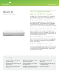
SSID settings are located under the Configure tab in the MCC. Figure 3 is a<br />
screenshot of the SSID Overview page:<br />
Figure 3 – SSID Overview Page<br />
The following elements can be configured on a per-SSID basis and are described<br />
in subsequent chapters:<br />
• Client IP addressing<br />
• LAN configuration (e.g., VLAN tagging)<br />
• Wireless encryption and authentication (e.g., WPA2-Personal, WPA2-<br />
Enterprise with 802.1x authentication)<br />
• User access control (e.g., per-user and group policies)<br />
• Traffic shaping (eg. application-specific usage policies)<br />
• Wireless features (e.g., band steering)<br />
• Branding (e.g., splash page / captive portal)<br />
<strong>Meraki</strong> <strong>Cloud</strong> <strong>Controller</strong> <strong>Product</strong> <strong>Manual</strong> | 17
5 Assigning IP Addresses to Wireless Clients<br />
The administrator can assign IP addresses to wireless clients via one of the<br />
following two addressing modes. The addressing mode is configured on a per-<br />
SSID basis under the Configure tab on the Access Control page.<br />
5.1 NAT Mode<br />
In NAT mode, the <strong>Meraki</strong> APs run as DHCP servers to assign IP addresses to<br />
wireless clients out of a private 10.x.x.x IP address pool behind a NAT.<br />
NAT mode should be enabled when any of the following is true:<br />
• Wireless clients associated to the SSID require Internet-only access.<br />
• There is no DHCP server on the LAN that can assign IP addresses to<br />
the wireless clients.<br />
• There is a DHCP server on the LAN, but it does not have enough IP<br />
addresses to assign to wireless clients.<br />
• There are multiple DHCP servers in the network assigning IP addresses<br />
from different subnets. This is common when there are heterogeneous<br />
backhaul connections (e.g., some APs in the network obtain Internet<br />
connectivity from a T1, while other APs in the same network obtain<br />
Internet connectivity from a business-class DSL).<br />
The implications of enabling NAT mode are as follows:<br />
• Devices outside of the wireless network cannot initiate a connection to a<br />
wireless client.<br />
• Wireless clients cannot use Layer 2 discovery protocols to find other<br />
devices on either the wired or wireless network.<br />
• Legacy VPN clients (i.e., those that do not support NAT Traversal) may<br />
not be able to establish IPSec tunnels over the wireless network. (One<br />
workaround is to upgrade the VPN client or configure the VPN client to<br />
establish an IPSec tunnel over TCP, e.g. SSL.)<br />
• VLAN tagging wireless traffic is not supported in NAT mode.<br />
5.2 Bridge Mode (Enterprise Only)<br />
In bridge mode, the <strong>Meraki</strong> APs act as bridges, allowing wireless clients to obtain<br />
their IP addresses from an upstream DHCP server.<br />
Bridge mode should be enabled when any of the following is true:<br />
• Wired and wireless clients in the network need to reach each other<br />
(e.g., a wireless laptop needs to discover the IP address of a network<br />
<strong>Meraki</strong> <strong>Cloud</strong> <strong>Controller</strong> <strong>Product</strong> <strong>Manual</strong> | 18
printer, or wired desktop needs to connect to a wireless surveillance<br />
camera).<br />
• Layer 2 multicast and broadcast packets (e.g., ARP, Bonjour) need to<br />
propagate in a limited manner to both wired and wireless clients for<br />
device discovery, networking, etc.<br />
• The wireless network needs to support legacy VPN clients (i.e., those<br />
that do not support NAT Traversal).<br />
• Wired and wireless clients need to have IP addresses in the same<br />
subnet for monitoring and/or access control reasons (e.g., a web<br />
gateway in the network allows/denies Internet access based on the<br />
client’s IP address).<br />
• Wireless traffic needs to be VLAN-tagged between the <strong>Meraki</strong> AP and<br />
the upstream wired infrastructure.<br />
The implications of enabling bridge mode are as follows:<br />
• An administrator cannot enable adult content filtering on the SSID.<br />
Because the adult content filtering feature is DNS-based, bridge mode<br />
disables adult content filtering by using the DNS server(s) advertised by<br />
the network’s DHCP server.<br />
• Multiple DHCP servers are allowed, but they must assign IP addresses<br />
to wireless clients from the same subnet. This enables these IP<br />
addresses to be routed by the LAN to which the <strong>Meraki</strong> APs are<br />
connected.<br />
5.3 VPNs<br />
<strong>Meraki</strong> supports most VPN solutions by default. Any IPSec implementation that<br />
has support for NAT Traversal (NAT-T) will work on a <strong>Meraki</strong> network. Certain<br />
IPSec-based VPN solutions do not work well behind a NAT. If difficulties occur<br />
when using VPNs, an administrator should consider switching VPN clients to use<br />
SSL instead of IPSec, or enabling bridge mode as the wireless client IP<br />
addressing mode. Note that most wireless networking solutions that use NAT<br />
share the same problems with IPSec VPNs.<br />
<strong>Meraki</strong> <strong>Cloud</strong> <strong>Controller</strong> <strong>Product</strong> <strong>Manual</strong> | 19
6 Configuring the LAN<br />
The following section describes how to configure your LAN to support a <strong>Meraki</strong><br />
system. While a <strong>Meraki</strong> wireless network imposes minimal requirements on the<br />
wired LAN infrastructure, some small changes may be required.<br />
6.1 Firewall Settings<br />
If a firewall is in place, it must allow outgoing connections on particular ports to<br />
particular IP addresses. The most current list of outbound ports and IP<br />
addresses can be found here:<br />
http://tinyurl.com/y79une3<br />
6.2 Assigning IP Addresses to <strong>Meraki</strong> APs<br />
All <strong>Meraki</strong> gateway APs (APs with Ethernet connections to the LAN) must be<br />
assigned routable IP addresses. These IP addresses can be configured directly<br />
on each AP (see instructions below), or assigned to the APs via an upstream<br />
DHCP server.<br />
In general, static IP address assignment is recommended for <strong>Meraki</strong> APs, even<br />
when the APs obtain their IP addresses via DHCP. (The DHCP server should be<br />
configured to assign a static IP address for each MAC address belonging to a<br />
<strong>Meraki</strong> AP.) Other features of the wireless network, such as 802.1x<br />
authentication, may rely on the property that the APs have static IP addresses.<br />
6.2.1 Configuring a Static IP Address Directly on a <strong>Meraki</strong> AP<br />
A static IP address can be configured directly on a given AP through the<br />
following steps:<br />
1. Using a client machine (e.g., a laptop), connect to the AP either<br />
wirelessly (by associating to any SSID broadcasted by the AP) or over a<br />
wired connection (by plugging one end of an Ethernet cable into the<br />
client machine, and the other end of the Ethernet cable into the AP’s<br />
Ethernet jack; it may be necessary to unplug the AP from its existing<br />
Ethernet connection in order to connect the client machine).<br />
2. Using a web browser on the client machine, access the AP’s built-in<br />
web server by browsing to http://my.meraki.com.<br />
3. Click on the “Static IP Configuration” tab. You will be prompted to login.<br />
The default username is “admin” and the default password is the AP’s<br />
serial number, with hyphens included.<br />
4. Configure the static IP address, net mask, gateway IP address, and<br />
DNS servers that this AP will use on its wired connection to the Internet.<br />
5. If necessary, reconnect the AP to its Ethernet connection to the LAN.<br />
<strong>Meraki</strong> <strong>Cloud</strong> <strong>Controller</strong> <strong>Product</strong> <strong>Manual</strong> | 20
6.2.2 Configuring a Static IP Address for a <strong>Meraki</strong> AP via DHCP Reservations<br />
Instead of associating to each <strong>Meraki</strong> AP and configuring a static IP address on<br />
each AP, an administrator can configure static IP addresses to assign to <strong>Meraki</strong><br />
APs on the upstream DHCP server. Through “DHCP reservations”, IP addresses<br />
are “reserved” for the MAC addresses of the <strong>Meraki</strong> APs. Please consult the<br />
documentation for the DHCP server to configure DHCP reservations.<br />
<strong>Meraki</strong> <strong>Cloud</strong> <strong>Controller</strong> <strong>Product</strong> <strong>Manual</strong> | 21
7 Wireless Encryption and Authentication<br />
The MCC supports a wide variety of encryption and authentication methods—<br />
from simple, open access to WPA2-Enterprise with 802.1x authentication. This<br />
chapter explains the different encryption and authentication modes available in<br />
the MCC.<br />
Encryption and authentication are configured in the MCC under the Configure tab<br />
on the Access Control page. Generally speaking, the encryption method is<br />
configured under “Association requirements”, while the authentication method is<br />
configured under “Network sign-on method”. To associate to a wireless network,<br />
a client must have the correct encryption keys (association requirements). Once<br />
associated the wireless client may need to enter information (network sign-on<br />
method) before accessing resources on the wireless network.<br />
The combinations of encryption and authentication methods that are supported<br />
are as follows:<br />
Network sign-on method<br />
Association<br />
requirements<br />
Direct<br />
access<br />
Clickthrough<br />
splash page<br />
Sign-on<br />
splash page<br />
Billing (paid<br />
access)<br />
Open (no<br />
encryption)<br />
MAC-based<br />
access control<br />
(no encryption)<br />
WEP (shared<br />
network key)<br />
WPA2-PSK<br />
(shared<br />
network key)<br />
WPA2-<br />
Enterprise with<br />
802.1x<br />
authentication<br />
ü ü ü ü<br />
ü<br />
ü<br />
ü ü ü<br />
ü ü ü<br />
ü<br />
ü<br />
7.1 Association Requirements<br />
In the “Association requirements” of the Access Control page, an administrator<br />
configures the parameters that need to be satisfied at wireless association time<br />
in order for a device to connect successfully to a wireless network.<br />
<strong>Meraki</strong> <strong>Cloud</strong> <strong>Controller</strong> <strong>Product</strong> <strong>Manual</strong> | 22
7.1.1 Open<br />
7.1.2 MAC-Based Access Control (Enterprise Only)<br />
Open mode allows any device to connect to the wireless network. The major<br />
advantage of open mode is its simplicity: Any client can connect easily and<br />
without complex configuration. Open mode is recommended when there are<br />
guests who need to get onto the network, or more generally, when ease of<br />
connectivity is paramount and access control is not required.<br />
In most environments, the administrator should ensure that wireless clients<br />
associated on an open network cannot access LAN resources, such as file<br />
shares. Administrators can control access using VLAN tagging, the LAN isolation<br />
feature, or custom firewall rules (see Section 10.6.2, “Custom Firewall Rules<br />
(Enterprise Only)”).<br />
MAC-based access control admits or denies wireless association based on the<br />
connecting device’s MAC address. When a wireless device attempts to<br />
associate, the <strong>Meraki</strong> AP queries a customer-premise RADIUS server with an<br />
Access-Request message. The RADIUS server can admit or deny the device<br />
based on the MAC address, responding to the <strong>Meraki</strong> AP with either an Access-<br />
Accept message or an Access-Reject message, respectively.<br />
This authentication method requires no client-side configuration. However, it<br />
suffers from a poor user experience. Wireless clients that are denied wireless<br />
association simply cannot connect to the SSID, and they do not receive any<br />
explicit notification about why they cannot connect.<br />
If this authentication method is selected, at least 1 RADIUS server must be<br />
configured on the Access Control page in the “RADIUS for MAC-based access<br />
control” section. This section includes a test tool that simulates the wireless<br />
device connecting to every <strong>Meraki</strong> AP in the network. (See Section 7.3,<br />
“Configuring an Authentication Server”, for more information.)<br />
7.1.3 Pre-Shared Keys (WEP, WPA/WPA2-Personal)<br />
A pre-shared key (PSK) allows anyone who has the key to use the wireless<br />
network.<br />
Wired Equivalent Privacy (WEP) is the original 802.11 pre-shared key<br />
mechanism, utilizing RC4 encryption. WEP is vulnerable to being hacked; the<br />
encryption key can be derived by an eavesdropper who sees enough traffic. Only<br />
use WEP if it is not possible to utilize more advanced security—for instance,<br />
when there are legacy client devices in the network that do not support<br />
WPA/WPA2.<br />
WPA- and WPA2-Personal (Wi-Fi Protected Access) use stronger encryption<br />
than WEP. (WPA-Personal uses TKIP with RC4 encryption, while WPA2-<br />
Personal uses AES encryption.) WPA2-Personal is preferred.<br />
Though it requires some client-side configuration, a PSK is relatively easy to<br />
configure. It can be a good choice when there is a small number of users or<br />
when clients do not support more sophisticated authentication mechanisms, such<br />
as WPA2-Enterprise. A deployment based on a PSK does not scale well,<br />
<strong>Meraki</strong> <strong>Cloud</strong> <strong>Controller</strong> <strong>Product</strong> <strong>Manual</strong> | 23
however. With a large number of users, it becomes more difficult to change the<br />
PSK, an operation that should be performed periodically to ensure that the PSK<br />
has not been shared with unwanted users.<br />
7.1.4 WPA2-Enterprise with 802.1x Authentication (Enterprise Only)<br />
802.1x is an IEEE standard framework for encrypting and authenticating a user<br />
who is trying to associate to a wired or wireless network. WPA-Enterprise uses<br />
TKIP with RC4 encryption, while WPA2-Enterprise adds AES encryption.<br />
802.1x can be transparent to wireless users. For example, Windows machines<br />
can be configured for single sign-on, such that the same credentials that a user<br />
enters to log into his machine are passed automatically to the authentication<br />
server for wireless authentication. The user is never prompted to re-enter his<br />
credentials.<br />
802.1x utilizes the Extensible Authentication Protocol (EAP) to establish a secure<br />
tunnel between participants involved in an authentication exchange. The MCC<br />
supports multiple EAP types, depending on whether the network is using a<br />
<strong>Meraki</strong>-hosted authentication server or a customer-hosted authentication server.<br />
(See Section 7.3, “Configuring an Authentication Server”, for more information.)<br />
The following table shows the EAP types supported by the MCC:<br />
EAP Mode Customer RADIUS <strong>Meraki</strong> RADIUS<br />
PEAPv0/EAP-MSCHAPv2 ü ü<br />
EAP-TTLS/MSCHAPv2 ü ü<br />
EAP-TLS<br />
PEAPv1/EAP-GTC<br />
ü<br />
ü<br />
WPA2-Enterprise with 802.1x authentication is typically used with a customerpremise<br />
RADIUS server. The RADIUS server must be configured to allow<br />
authentication requests from the IP addresses of the <strong>Meraki</strong> APs. This<br />
configuration is necessary to successfully complete the EAP exchange and is<br />
one more reason to configure static IP addresses on the <strong>Meraki</strong> APs.<br />
Note: 802.1x is typically only performed once a user’s credentials have been<br />
entered into the machine. If you would like to be able to authenticate a machine<br />
before the user signs in (also known as “machine authentication”), please see the<br />
<strong>Meraki</strong> Knowledge Base online.<br />
7.2 Network Sign-On Methods<br />
The network sign-on method is the mechanism by which a wireless client gains<br />
access to network resources. It occurs after a wireless client has associated to<br />
an SSID.<br />
<strong>Meraki</strong> <strong>Cloud</strong> <strong>Controller</strong> <strong>Product</strong> <strong>Manual</strong> | 24
7.2.1 Direct Access<br />
7.2.2 Click-Through Splash Page<br />
7.2.3 Sign-On Splash Page<br />
With direct access, a wireless client is granted network access as soon as he<br />
associates to the SSID. No splash page is presented to the wireless client.<br />
When configured, a click-through splash page displays a fully customizable<br />
HTML page to the wireless client the first time the client makes an HTTP request.<br />
An administrator may use this splash page to display an acceptable use policy or<br />
network announcements. The client is only granted network access after clicking<br />
the “Continue” button on the splash page.<br />
The click-through splash page is hosted by the MCC. As such, the network must<br />
have connectivity to the MCC in order to display the splash page. If the MCC is<br />
unreachable for some reason, the administrator can configure whether new<br />
wireless users should be admitted to the wireless network without seeing the<br />
splash page. This setting is under the Configure tab on the Access Control page<br />
in the “Disconnection behavior” section.<br />
While the click-through splash page requires no client-side configuration, it<br />
should only be enabled on an SSID whose clients are all capable of displaying<br />
the splash page. When there are clients that are not browser-capable (e.g.,<br />
wireless barcode scanners), the splash page should be disabled on the SSID. An<br />
administrator can configure whether new wireless clients are able to obtain<br />
network access when the click-through splash page cannot be displayed (i.e.,<br />
when the MCC becomes temporarily unavailable).<br />
See Chapter 16, “Branding”, for additional information on customizing the clickthrough<br />
splash page, including the ability to configure the splash page interval.<br />
A sign-on splash page provides the functionality of the click-through splash page,<br />
but adds the ability to prompt the wireless client for a username and password.<br />
The client is only granted network access after he enters a username and<br />
password that are validated against a backend authentication server (either a<br />
<strong>Meraki</strong>-hosted authentication server or a customer-hosted RADIUS, Active<br />
Directory or LDAP server). (See Section 7.3, “Configuring an Authentication<br />
Server”, for more information.)<br />
The sign-on splash page may be hosted by the MCC or on an external web<br />
server (see Section 16.1, “Splash Page”). An administrator can configure<br />
whether new wireless clients are able to obtain network access when the sign-on<br />
splash page cannot be displayed or when the username/password credentials<br />
cannot be validated (i.e., the authentication server is unreachable). This setting<br />
is under the Configure tab on the Access Control page in the “Disconnection<br />
behavior” section.<br />
Sign-on splash page is an authentication option that requires no client-side<br />
configuration. In addition, it is secured by SSL (HTTPS), so that usernames and<br />
passwords are sent to the MCC confidentially. However, when enabled, it<br />
requires clients to remember usernames and passwords, which they will need to<br />
<strong>Meraki</strong> <strong>Cloud</strong> <strong>Controller</strong> <strong>Product</strong> <strong>Manual</strong> | 25
enter periodically. As with the click-through splash page, clients that are<br />
incapable of displaying the splash page need to be considered.<br />
See Section 16.1, “Branding”, for additional information on customizing the<br />
splash pages or using an externally.<br />
7.2.4 Billing<br />
When configuring an SSID as a wireless hotspot, an administrator can utilize<br />
<strong>Meraki</strong>’s integrated billing features to grant network access only to paying users.<br />
For additional information on integrated billing, see Chapter 17, “Billing”.<br />
7.2.5 Hosting Your Own Splash Page<br />
<strong>Meraki</strong> also supports the ability for you to host splash pages on your own web<br />
server. This capability is referred to as “EXCAP” for externally hosted captive<br />
portals. For additional information, please search for EXCAP in the <strong>Meraki</strong><br />
Knowledge Base.<br />
7.3 Configuring an Authentication Server<br />
7.3.1 <strong>Meraki</strong>-Hosted Authentication Server<br />
There are 5 different applications of authentication servers that are supported by<br />
the MCC:<br />
1. <strong>Meraki</strong>-hosted authentication server<br />
2. Externally hosted RADIUS server for MAC-based access control and/or<br />
WPA2-Enterprise with 802.1x authentication<br />
3. Externally hosted RADIUS server for sign-on splash page authentication<br />
4. Externally hosted Active Directory server for sign-on splash page<br />
authentication<br />
5. Externally hosted LDAP server for sign-on splash page authentication<br />
The authentication server type is configured on a per-SSID basis under the<br />
Configure tab on the Access Control page. For instance, an administrator could<br />
use the <strong>Meraki</strong>-hosted authentication server to manage guest user accounts for<br />
the guest SSID, while using a customer-hosted RADIUS or Active Directory<br />
server to authenticate employees for the employee SSID.<br />
The <strong>Meraki</strong>-hosted authentication server is configured through the MCC. For<br />
each user account, an administrator can configure the user’s name, the e-mail<br />
address and password that the user will use to log in, and optionally, an<br />
expiration time (to create a user account that self-expires after some period of<br />
time).<br />
The option to select a <strong>Meraki</strong>-hosted authentication server appears when any of<br />
the following is configured:<br />
• Sign-on splash page<br />
<strong>Meraki</strong> <strong>Cloud</strong> <strong>Controller</strong> <strong>Product</strong> <strong>Manual</strong> | 26
7.3.2 Externally Hosted RADIUS Server<br />
• WPA2-Enterprise with 802.1x authentication<br />
On the Access Control page, an administrator can create, edit, and remove user<br />
accounts. An expiration time can also be configured on a user account, so that<br />
the account becomes invalid after a certain amount of time elapses. (This<br />
feature is useful for guest accounts.) Finally, the Access Control page provides<br />
an option for “self-registration”, which allows users to create their own accounts.<br />
However, administrators still need to manually add those accounts to the list of<br />
users allowed on the network before the account has access.<br />
User accounts configured in the <strong>Meraki</strong>-hosted authentication server are global<br />
to the networks in the organization. So, a password change to a user account in<br />
one network applies to other networks in which the user account may be used.<br />
(For more information, see Section 18.1, “Organizations”.)<br />
<strong>Meraki</strong> APs must be able to reach the MCC in order to use the <strong>Meraki</strong>-hosted<br />
authentication server. If the MCC becomes temporarily unavailable, existing<br />
wireless clients (already authenticated) remain connected, but new wireless<br />
clients are unable to authenticate to access the wireless network. An<br />
administrator can configure whether new wireless clients are able to obtain<br />
network access when the MCC is unavailable under the Configure tab on the<br />
Access Control page in the “Disconnection behavior” section.<br />
Many organizations have an existing user authentication or directory server that<br />
they would like to use to control access to the wireless LAN. Common server<br />
types include LDAP and Active Directory. Any type of authentication server with<br />
a RADIUS interface can be integrated with a <strong>Meraki</strong> wireless network. The MCC<br />
allows an administrator to configure multiple RADIUS servers for failover.<br />
When an externally hosted RADIUS server is used with either MAC-based<br />
access control or WPA2-Enterprise with 802.1x authentication, the <strong>Meraki</strong> APs<br />
must be able to reach the RADIUS server. The MCC offers a test tool that<br />
enables an administrator to verify connectivity of all of the <strong>Meraki</strong> APs to the<br />
RADIUS server, and to check a particular set of user credentials against the<br />
RADIUS server. The test tool appears under the Configure tab on the Access<br />
Control page.<br />
When an externally hosted RADIUS server is used with sign-on splash page, an<br />
administrator can configure the <strong>Meraki</strong> wireless network to use an externally<br />
hosted RADIUS server for user authentication. The MCC acts as an<br />
intermediary in this configuration to provide (1) a consistent end user experience<br />
(e.g., the wireless user is not presented with the splash page again if he reassociates<br />
to another AP) and (2) RADIUS accounting features (see “Appendix<br />
C: RADIUS ”).<br />
If the sign-on splash page is hosted by the MCC, the conversation is a<br />
straightforward RADIUS exchange between the MCC and the external RADIUS<br />
server.<br />
<strong>Meraki</strong> <strong>Cloud</strong> <strong>Controller</strong> <strong>Product</strong> <strong>Manual</strong> | 27
If the sign-on splash page is itself externally hosted, the conversation involves<br />
exchanges between the splash page server, the MCC, and the RADIUS server.<br />
Specifically:<br />
1. The wireless client associates with the <strong>Meraki</strong> wireless network.<br />
2. The user makes an initial request for a URL in his web browser.<br />
3. The <strong>Meraki</strong> AP redirects the user to a URL on the splash page server.<br />
(The administrator configures this URL in the MCC, under the Configure<br />
tab on the Splash Page page.) When the <strong>Meraki</strong> AP redirects the user<br />
to the splash page server, it includes the following HTTP parameters in<br />
the HTTP redirect:<br />
• continue_url: The URL that the user originally requested.<br />
This parameter may be interpreted by the splash page server<br />
to decide where the user should be redirected if he<br />
authenticates successfully.<br />
• login_url: The URL at the MCC to which the splash page<br />
server should send an HTTP POST with collected user<br />
credentials (see Step 4). This parameter is escaped to include<br />
the continue_url embedded within it, and should not be<br />
interpreted by the splash page server.<br />
• ap_mac: MAC address of the <strong>Meraki</strong> AP to which the user is<br />
associated.<br />
• ap_name: Name (if configured) of the <strong>Meraki</strong> AP to which the<br />
user is associated.<br />
• ap_tags: Tags (if configured) applied to the <strong>Meraki</strong> AP to<br />
which the user is associated.<br />
• mauth: An opaque string used by the MCC for authentication<br />
and security.<br />
4. The external splash page server presents the user with a web form that<br />
captures the user’s credentials and causes the user to send an HTTP<br />
POST to the MCC, using the URL specified in login_url (see Step 3).<br />
In this HTTP POST, the server includes the following parameters:<br />
• username: The username that the wireless user provided to<br />
the splash page server.<br />
• password: The password that the wireless user provided to<br />
the splash page server.<br />
• success_url (optional): The URL to which the wireless user is<br />
redirected if he passes authentication. The splash page server<br />
can use this parameter to override the continue_url that the<br />
user originally requested.<br />
<strong>Meraki</strong> <strong>Cloud</strong> <strong>Controller</strong> <strong>Product</strong> <strong>Manual</strong> | 28
7.3.3 Externally Hosted Active Directory Server<br />
5. The MCC receives the HTTP POST from the splash page server, and in<br />
turn, sends a RADIUS Access-Request to the external RADIUS server<br />
with the username and password.<br />
6. The RADIUS server processes the RADIUS Access-Request from the<br />
MCC, and responds to the MCC with a RADIUS Access-Accept or<br />
Access-Reject. The RADIUS server may optionally send RADIUS<br />
attributes to the MCC to enforce over the wireless user. (For a list of<br />
supported RADIUS attributes, see Section 26.1, “Authentication<br />
Attributes”.)<br />
7. The MCC processes the response from the RADIUS server and<br />
redirects the wireless user accordingly.<br />
a. If the MCC receives an Access-Accept message from the<br />
RADIUS server, the user has successfully authenticated. The<br />
MCC redirects the user to the original URL he requested<br />
(continue_url), or the URL specified by the splash page<br />
server in the (optional) success_url (see Step 4).<br />
b. If the MCC receives an Access-Reject message from the<br />
RADIUS server, the user has failed authentication and is<br />
redirected back to the splash page server’s URL (in Step 3).<br />
Because the MCC needs to contact an external RADIUS server, the MCC must<br />
be able to reach the RADIUS server. This requirement may necessitate firewall<br />
changes that allow inbound connections to the RADIUS server. If the RADIUS<br />
server becomes temporarily unavailable, existing wireless clients (already<br />
authenticated) remain connected, but new wireless clients are unable to<br />
authenticate to access the network.<br />
<strong>Meraki</strong> wireless networks can also integrate natively with Active Directory without<br />
requiring RADIUS when sign-on splash page is used. If your network does not<br />
require the additional configuration options provided by RADIUS integration,<br />
there are certain advantages if the APs can communicate directly with Active<br />
Directory without a RADIUS server acting as an intermediary. Native AD<br />
integration eliminates the need to configure Microsoft NPS (or any other RADIUS<br />
server). Also, when using RADIUS integration with multi-domain forests, for<br />
example a school that has one domain for faculty and another for students that is<br />
using sign-on splash authentication, users must remember to include their<br />
domain with their username, which can easily be forgotten. Or alternatively, a<br />
complex hierarchy of RADIUS proxy servers or custom scripts might be required<br />
to make the log in process easier for the user.<br />
In order to configure native Active Directory integration, sign-on splash must be<br />
configured and Use My Active Directory Server selected from the<br />
Authentication Server drop-down menu under Configure->Access control. (See<br />
Figure 4)<br />
<strong>Meraki</strong> <strong>Cloud</strong> <strong>Controller</strong> <strong>Product</strong> <strong>Manual</strong> | 29
Figure 4 - Configuring Sign-on Splash with Native Active Directory<br />
Once Active Directory server option has been selected, the internal IP addresses<br />
of any domain controllers that will be used for authentication should be entered,<br />
along with the credentials of an Active Directory administrator that has read rights<br />
to all domain controllers that will used. (See Figure 5)<br />
It is highly recommended that a separate account is created for the purpose of<br />
providing Active Directory authentication. Users should take the following steps to<br />
secure the account:<br />
1. Create a Global Security Group in your domain (or forest)<br />
2. Create a user account and add it to the new group.<br />
3. Update the user account so that the new Security group is the<br />
userʼs primary group.<br />
4. Remove the Domain Users group from the account.<br />
This will isolate the account from acting like a normal domain user.<br />
<strong>Meraki</strong> <strong>Cloud</strong> <strong>Controller</strong> <strong>Product</strong> <strong>Manual</strong> | 30
Figure 5 - Dashboard Active Directory Server Configuration<br />
7.3.4 Externally Hosted LDAP Server<br />
In addition, the Global Catalog (port 3269) must be enabled for each domain<br />
controller.<br />
Similarly to Active Directory, <strong>Meraki</strong> wireless networks can natively integrate with<br />
LDAP authentication servers when using sign-on splash page. The manner with<br />
which this authentication is configured is very similar to that described for Active<br />
Directory in Section 7.3.3. In order to configure native LDAP integration, sign-on<br />
splash must be configured and Use My LDAP Server selected from the<br />
Authentication Server drop-down menu under Configure->Access control. (See<br />
Figure 6)<br />
Figure 6 - Configuring Sign-on Splash with Native LDAP Authentication<br />
Once the LDAP server option has been selected, the internal IP addresses of<br />
any LDAP servers that will be used for authentication should be entered, along<br />
with the appropriate port number and the credentials of an LDAP administrator<br />
with administrative rights to all domains that will be used. The common name<br />
<strong>Meraki</strong> <strong>Cloud</strong> <strong>Controller</strong> <strong>Product</strong> <strong>Manual</strong> | 31
(cn) and domain components (dn) should be entered in the format shown in<br />
Figure 7.<br />
Figure 7 - Dashboard Native LDAP Authentication Server Configuration<br />
<strong>Meraki</strong> <strong>Cloud</strong> <strong>Controller</strong> <strong>Product</strong> <strong>Manual</strong> | 32
8 Monitoring<br />
This chapter describes the extensive monitoring features under the Monitor tab in<br />
the MCC.<br />
8.1 Overview Page<br />
The Overview page shows a summary of network usage and network status. An<br />
administrator can see how many users have associated to the network in the last<br />
day/week, how much data those users transferred in that timeframe, and how<br />
bandwidth usage has fluctuated over the last week (a network usage graph).<br />
The aerial map shows the latest information about the APs in the network. The<br />
options in the upper-right corner enable an administrator to view the APs on top<br />
of a graphical map, a satellite image, or a hybrid view. In the upper-left corner,<br />
the arrow controls enable the administrator to pan. Panning can also be achieved<br />
by clicking-and-dragging the map. Below the arrow controls, a scale control<br />
enables the administrator to adjust the zoom level. The zoom level can also be<br />
controlled with the magnifying glass next to the arrow controls, or by doubleclicking<br />
on a particular region to zoom into.<br />
On the map, the colored dots represent APs. The status of the AP is indicated<br />
by its color:<br />
• Green: The AP is not reporting any problems.<br />
• Yellow: The AP is up, but experienced a problem recently. In some<br />
cases, the administrator may be able to clear this alert on the Access<br />
Points page.<br />
• Red: The AP is currently down.<br />
• Gray: The AP has been down for more than 7 days.<br />
An administrator can click on an AP to get its name, its mesh mode (mesh<br />
gateway or mesh repeater), the number of users that have associated to it in the<br />
last 24 hours (also indicated by the number inside the AP), and the amount of<br />
data that it has transferred in the last 24 hours. Gray lines between APs<br />
represent mesh links. Mousing over a mesh repeater highlights a line that shows<br />
the path that the AP is taking through the mesh network to reach a mesh<br />
gateway (and the LAN).<br />
The “Options” box in the upper right part of the map lets users select what the<br />
numbers in the APs represent (e.g., number of clients connected or mesh hops<br />
to gateway), as well as preferences about how to display mesh links.<br />
The “Current clients” link under the network name in the upper left corner, when<br />
clicked, will open up a table showing a summary of the distribution of current<br />
clients at that moment across the various SSIDs and channels in the network.<br />
Clicking on the link directly above the network name in the upper left corner or<br />
selecting the All-network Overview option under the Network drop-down selector<br />
<strong>Meraki</strong> <strong>Cloud</strong> <strong>Controller</strong> <strong>Product</strong> <strong>Manual</strong> | 33
at the top of the screen will take the administrator to the All Network Overview<br />
page.<br />
8.2 All-Network Overview Page<br />
The all-network overview page shows a summary of all of the networks in a<br />
particular organization. The usage graph at the top summarizes cumulative<br />
usage across all networks, and the map shows network locations with markers<br />
that are color-coded to the networks listed in the network list to the left of the<br />
usage graph. If the user mouses over a network in the list, the network marker<br />
on the map will be highlighted along with the usage for that particular network in<br />
the usage graph. Clicking on a particular network marker on the map or network<br />
name in the list will allow the user to “drill down” to the Overview page for that<br />
particular network. Figure 8 is an example of an all-network Overview page.<br />
Figure 8 – All-Network Overview Page<br />
Configuring Sign-on Splash with Native Active Directory<br />
8.3 Maps Page (Enterprise Only)<br />
The Maps page enables an administrator to upload custom maps and floorplans<br />
for better network visualization. For instance, an administrator could upload<br />
multiple images to visualize AP placement on multiple floors of an office building,<br />
or different branch offices in the organization. Figure 9 is an example of an AP<br />
placement on a floorplan.<br />
<strong>Meraki</strong> <strong>Cloud</strong> <strong>Controller</strong> <strong>Product</strong> <strong>Manual</strong> | 34
Figure 9 – Maps Page<br />
An administrator can add a map or floorplan image (GIF, PNG, JPG, or PDF<br />
format up to 10 MB per image) under the Configure tab on the Maps &<br />
Floorplans page. This is also where an administrator would modify or delete an<br />
existing image. After uploading the image, the administrator can return to the<br />
Maps page to place APs on the image. The “Place APs” button in the upper-right<br />
corner produces a checklist of APs that the administrator can add to the image.<br />
The administrator then places the APs by dragging-and-dropping the AP icons<br />
onto the image.<br />
8.4 Access Points Page<br />
The Access Points page identifies the APs on the network and shows their<br />
status, activity, and usage. The top-level page provides a list of APs in the<br />
network. The Access Points page has the following features:<br />
• Can be sorted by clicking on a column header.<br />
• Columns can be added, removed, or reordered in the list by clicking on<br />
“Display Options”.<br />
• Search by AP name, serial number or MAC address<br />
Figure 10 is a screenshot that shows a top-level Access Points page.<br />
Figure 10 – Access Points Page<br />
<strong>Meraki</strong> <strong>Cloud</strong> <strong>Controller</strong> <strong>Product</strong> <strong>Manual</strong> | 35
8.5 Access Point Details Page<br />
To get additional information about an individual AP, an administrator can click<br />
on the AP in the list to bring up a page that contains the following:<br />
• Identifying information (e.g., MAC address, serial number, status)<br />
• Performance data (e.g., connectivity, throughput, latency, mesh<br />
neighbors), with zoom and pan features across various time ranges<br />
• Live tools for remote troubleshooting<br />
There are a variety of real-time tools that can be used for<br />
troubleshooting and debugging wireless issues remotely.<br />
Administrators can see a list of current clients associated to a particular<br />
AP and ping associated clients as well as the AP itself, run a throughput<br />
test, ping a particular MAC address and run an interference scan of the<br />
local RF environment (Caution: live interference scan will disconnect<br />
currently associated clients). Interference scan will also be discussed<br />
as part of the spectrum analysis capabilities in Section 15.5).<br />
• Link to the event log for this specific AP (see Section 8.7, “Event Log<br />
Page (Enterprise Only)”)<br />
• Lists of strong and weak mesh neighbors (adjacent APs in the mesh) in<br />
the Neighbors tables<br />
Figure 11 shows a screenshot of the AP details page.<br />
Figure 11 – AP Details Page<br />
Throughput statistics for mesh gateways are throughput numbers to meraki.com.<br />
Gateway speeds are often limited by the Internet uplink speed. Administrators<br />
should use these statistics to troubleshoot problems either within the LAN or with<br />
the Internet service provider.<br />
<strong>Meraki</strong> <strong>Cloud</strong> <strong>Controller</strong> <strong>Product</strong> <strong>Manual</strong> | 36
Throughput statistics for mesh repeaters are throughput numbers within the<br />
mesh network, not through the Internet uplink. As such, it is possible to see 6<br />
Mbps throughput within the mesh network, but 1.5 Mbps throughput through the<br />
DSL uplink. Administrators should use these statistics to troubleshoot problems<br />
within the wireless network, such as poor mesh connections or channel<br />
interference.<br />
8.5.1 AP Tagging<br />
A convenient way to make it easier to find, sort and filter APs in a large network<br />
with hundreds or thousands of APs is using AP tagging. Alphanumeric tags can<br />
be assigned to access points to create groups of APs by location (e.g.<br />
Building_1, Floor_4, West_Campus, etc.) or by other criteria. The Access Points<br />
page (See Section 8.4) is searchable by tag to make filtering for specific groups<br />
of APs fast and easy. Figure 12 shows a screenshot of an AP with the tag<br />
“Lobby” applied.<br />
Figure 12 - Access Point with Tag Applied<br />
Tags can be added to APs either individually or in groups. Figure 13 - Editing AP<br />
Configuration to Add Tag<br />
Figure 14 and Figure 14 show how to add a tag to an individual AP by editing its<br />
configuration.<br />
<strong>Meraki</strong> <strong>Cloud</strong> <strong>Controller</strong> <strong>Product</strong> <strong>Manual</strong> | 37
Figure 13 - Editing AP Configuration to Add Tag<br />
Figure 14 - Adding a Tag to an Individual AP<br />
Figure 15 illustrates how to add a tag to a group of APs from the Access Points<br />
page.<br />
<strong>Meraki</strong> <strong>Cloud</strong> <strong>Controller</strong> <strong>Product</strong> <strong>Manual</strong> | 38
Figure 15 - Adding Tags to Many APs<br />
8.6 Clients Page<br />
The Clients page shows how the network is being used and by which client<br />
devices. Figure 16 is a screenshot of the Clients page:<br />
Figure 16 – Clients Page<br />
8.6.1 Clients Overview Page Features<br />
The Clients page has the following features:<br />
• Displays clients that have associated on any SSID advertised by the<br />
wireless network, or only those clients that have associated on a given<br />
SSID. This can be selected using the SSID drop down menu at the top<br />
of the screen.<br />
<strong>Meraki</strong> <strong>Cloud</strong> <strong>Controller</strong> <strong>Product</strong> <strong>Manual</strong> | 39
8.6.2 Traffic Analysis (Enterprise Only)<br />
• Search for clients by MAC, OS, device type or NetBIOS/Bonjour name.<br />
• Zoom control, which enables the administrator to see only those clients<br />
that have associated within the specified time span.<br />
• The administrator can also click on the “blocked list” to view only those<br />
clients on the MAC blacklist (see Section 10.3, “MAC Blacklist”).<br />
• Like the Access Points page, the Clients page has a list that can be<br />
customized (adding, removing, and reordering columns) and resorted<br />
(by clicking on a column header).<br />
• The “Description” column shows the device name, if it can be<br />
determined (i.e., through NetBIOS); otherwise, it simply displays the<br />
device’s MAC address.<br />
• The “Operating system” column shows the operating system of the<br />
device, which is determined through OS fingerprinting (the unique<br />
pattern by which a particular operating system requests an IP address<br />
via DHCP).<br />
• An administrator can mouse over a row in the device list to see a new<br />
line appear in the usage graph, which depicts the fraction of total<br />
bandwidth that the highlighted device used.<br />
<strong>Meraki</strong> Enterprise networks offer powerful application visibility and control tools.<br />
Packet inspection engines running custom parsers in each AP provide this<br />
information by fingerprinting and identifying applications and application groups.<br />
Traffic Shaper (to be discussed in Section 12) then provides the ability to create<br />
custom per-user shaping policies based on this application-level visibility. Since<br />
<strong>Meraki</strong>’s parsers are designed to run at line rate, there is no performance<br />
decrease when enabling Traffic Analysis or Traffic Shaping<br />
Next to the usage graph at the top of the screen is a pie chart that can display a<br />
breakdown of the traffic currently displayed on the page by application, HTTP<br />
content type, port number or custom criteria. The gray arrows flip from one chart<br />
to the next. Custom pie charts can be configured on the Network-wide Settings<br />
page under the Configure tab.<br />
Clicking on either the pie chart itself or the “More” link underneath the pie chart<br />
will open up the Traffic Analysis Details page, showing a detailed list of the<br />
specific applications and content types that make up the data shown in the pie<br />
chart. The applications have been assigned to groups to make classifying<br />
applications and creating shaping policies simpler. An up to date list of which<br />
applications are included in each group can be found here:<br />
http://bit.ly/cUFXnv<br />
The percent of total usage is shown by application as well as by application<br />
group. Figure 17 shows a screen shot of the Clients page with the Traffic<br />
Analysis details page expanded.<br />
<strong>Meraki</strong> <strong>Cloud</strong> <strong>Controller</strong> <strong>Product</strong> <strong>Manual</strong> | 40
Figure 17 - Traffic Analysis Details Page<br />
Clicking on a particular application or content type within the Traffic Analysis<br />
Details page will take you to the Rule Details page, where you will find detailed<br />
information about that particular application or content type rule, including which<br />
users are contributing to usage of this type and details such as which application<br />
group that item belongs to, port number, description of the application or rule and<br />
links to additional information. Figure 18 shows the Rule Details page for Netflix,<br />
a video streaming site.<br />
Figure 18 - Rule Details Page<br />
8.6.3 Client Details Page<br />
An administrator can click on a particular device in the device list to obtain<br />
additional information about the wireless client. Figure 19 is a screenshot of the<br />
Client details page for a specific device.<br />
<strong>Meraki</strong> <strong>Cloud</strong> <strong>Controller</strong> <strong>Product</strong> <strong>Manual</strong> | 41
Figure 19 – Information about a Specific Client<br />
This page provides detailed information about the client device and user as well<br />
as their network usage. Features include:<br />
• Client configuration details<br />
At the top of the page administrators can see detailed information about<br />
this particular client, including MAC address and IP address, device<br />
type and manufacturer, operating system, Bonjour/DHCP/NetBIOS<br />
hostname, wireless card capabilities, most recent SSID, AP and time on<br />
the network as well as Active Directory username for most recent user.<br />
• Client location<br />
The approximate location of the wireless client is indicated on a Google<br />
map or a custom floor plan. More details about Client Location Services<br />
can be found in section 8.5.4.<br />
• Traffic analysis<br />
Pie charts similar to those on the Client Overview page show details<br />
about this particular client’s usage of the network.<br />
• Dynamic access control<br />
On this page, an administrator can create a dynamic access control<br />
policy to either block a wireless device or bypass the wireless device<br />
from seeing a splash page. (To configure these settings, an<br />
administrator clicks the “Edit” button to change the “Network access”<br />
field to either “normal”, “blocked”, or “whitelisted”.) Optionally, the<br />
administrator can configure a message that appears on the block page<br />
for a blacklisted user.<br />
• Event log<br />
This page also provides a link to the event log for this specific client<br />
(see Section 8.7, “Event Log Page (Enterprise Only)”).<br />
<strong>Meraki</strong> <strong>Cloud</strong> <strong>Controller</strong> <strong>Product</strong> <strong>Manual</strong> | 42
8.6.4 Client Location Services<br />
• Live tools<br />
Similar to the live tools on the AP details page, an administrator can<br />
locate a client, ping a client or even see a real-time packet counter<br />
showing the user’s activity from this page.<br />
In the upper-right corner of the Client details page is a map where the<br />
approximate location of the client is indicated with a blue dot. Figure 20 below is<br />
a screenshot of the client location map.<br />
Figure 20 - Client Location Map on Client Details Page<br />
Client location is determined using advanced triangulation techniques that<br />
employ calibrated weighted averages and AP selection algorithms to ensure<br />
accuracy. Data from up to the last 24 hours will be used to calculate client<br />
location. In order to view a client’s location on a custom floor plan, all of the AP’s<br />
that “see” the client that were used to calculate location must be located on the<br />
same floor plan. Otherwise, the client’s location can still be viewed on a Google<br />
map. To update the client location data from the access point the client is<br />
currently associated to, click the “Locate Client’ button under the Live Tools<br />
section of this page.<br />
To ensure location accuracy, at least three access points are required. In<br />
addition, the access points should not be deployed such that all of the access<br />
points are in a linear pattern (see Figure 21 below). In this situation, client<br />
location will always appear that they are in line with the access points.<br />
<strong>Meraki</strong> <strong>Cloud</strong> <strong>Controller</strong> <strong>Product</strong> <strong>Manual</strong> | 43
Figure 21 - Poor AP Deployment for Accurate Location<br />
For best accuracy, the access points should be deployed in a non-linear pattern,<br />
or scatter pattern (see Figure 22 below).<br />
Figure 22 - Good AP Deployment for Accurate Location<br />
8.7 Event Log Page (Enterprise Only)<br />
The Event Log page provides detailed logging about various client activities,<br />
including the following:<br />
• Associations/disassociations<br />
• Authentication attempts and outcomes<br />
• DHCP activity<br />
• Initial traffic<br />
An administrator can use these logs to troubleshoot a client that may be<br />
experiencing issues on the wireless network. Figure 23 is a screenshot of an<br />
Event Log page.<br />
<strong>Meraki</strong> <strong>Cloud</strong> <strong>Controller</strong> <strong>Product</strong> <strong>Manual</strong> | 44
Figure 23 – Event Log Page<br />
The Event Log page allows an administrator to adjust the time interval over which<br />
the event log reports. In addition, the Event Log page supports the search tool.<br />
(See Section 8.11, “Search Tool”.) The administrator can view the event log for a<br />
given AP or a given client. Both filters can be applied through the search tool, or<br />
by accessing the event log links through the Access Points page and Clients<br />
page, respectively.<br />
8.8 Rogue APs Page (Enterprise Only)<br />
The Rogue APs page lists nearby APs that are detected by the <strong>Meraki</strong> APs<br />
during periodic scans. (See Chapter 12, “Rogue AP Detection (Enterprise<br />
Only)”.)<br />
8.9 Summary Report Page (Enterprise Only)<br />
An administrator can obtain network analytics from the Summary Report page<br />
under the Monitor tab. This report provides information about the usage and<br />
uptime of the <strong>Meraki</strong> wireless network, and can be e-mailed on a configurable<br />
schedule for constant visibility. Administrators can also add their organization’s<br />
logo to the report.<br />
8.10 Live Updates (Enterprise Only)<br />
The Maps, Access Points, and Clients pages under the Monitor tab support live<br />
updates, which provide real-time information about network status and client<br />
usage. An administrator can click on the “Live updates” link on a page on which<br />
the feature is offered. When live updates are enabled, the MCC will fetch up-todate<br />
information for that page from the wireless network approximately every 30<br />
seconds, for as long as the administrator stays on the page. (The live updates<br />
are disabled as soon as the administrator browses to a different page.) Live<br />
updates are an effective way to troubleshoot and closely monitor AP status (e.g.,<br />
when an AP loses network connectivity) and client usage (e.g., to see which<br />
clients are currently associated to the wireless network and how much bandwidth<br />
they are using).<br />
<strong>Meraki</strong> <strong>Cloud</strong> <strong>Controller</strong> <strong>Product</strong> <strong>Manual</strong> | 45
8.11 Search Tool<br />
The Maps, Access Points, Clients, Event Log, and Rogue APs pages under the<br />
Monitor tab all have search capabilities, which enable an administrator to find or<br />
filter a list of APs or wireless devices with tremendous flexibility and ease. Any<br />
string can be entered; the MCC will attempt to match on that string across all<br />
available fields. For example, an administrator can search/filter by device<br />
description, Ethernet address, or IP address. In addition, searches can be<br />
bookmarked for future use.<br />
The search tool also supports a number of keywords, which can be used to<br />
search/filter by specific characteristics. For example, an administrator can<br />
search/filter on a combination of strings, usage data, or mesh hop count. All of<br />
the available keyword options are enumerated in the “Help” link next to the<br />
search tool.<br />
The search tool operates instantaneously over the data in the AP or device list. It<br />
is an effective way to manage and monitor a large number of APs and/or a large<br />
number of wireless clients.<br />
8.12 Email Alerts<br />
Administrators can subscribe to receive email alerts from the MCC about various<br />
notable network events. Events that can trigger alerts include AP or network<br />
outages, detection of new rogue APs or configuration changes being saved in<br />
Dashboard by administrators. The time sensitivity of these alerts are<br />
configurable from five minutes to one hour, which can help to reduce false<br />
positives.<br />
Alerts are configured under the Configure tab on the Network-Wide Settings<br />
page.<br />
8.13 Export XML Data<br />
List data on the Access Points and Clients pages can be exported in XML format<br />
for further processing and analysis outside of the MCC. An administrator can<br />
click on the “Download as XML” link to retrieve the data. Most spreadsheet<br />
programs, such as Microsoft Excel, can open an XML file.<br />
8.14 Logins Page<br />
While the Clients page shows a list of devices, the Logins page shows a list of<br />
users. A user can login with multiple devices.<br />
The Logins page shows users who have logged in with one of the following<br />
authentication methods:<br />
• Sign-on splash pages with a <strong>Meraki</strong>-hosted authentication server<br />
• Billing logins<br />
<strong>Meraki</strong> <strong>Cloud</strong> <strong>Controller</strong> <strong>Product</strong> <strong>Manual</strong> | 46
Like the Clients page, the Logins page allows an administrator to filter users by<br />
the SSID on which they associated, display different columns of information, sort<br />
by different columns, and adjust the zoom level by timeframe.<br />
8.15 Account Activity Page<br />
The Account Activity page provides transaction information for networks that use<br />
<strong>Meraki</strong>’s integrated billing. Payments received from an end user appear as a<br />
credit, while payments made from <strong>Meraki</strong> to the network administrator appear as<br />
a debit. Transactions also show the timestamp, the user’s login name, the MAC<br />
address of the device from which the user made a payment, and the price plan<br />
the user purchased. Administrators may view the transaction history for any<br />
given month. (For more information, see Chapter 17, “Billing”.)<br />
<strong>Meraki</strong> <strong>Cloud</strong> <strong>Controller</strong> <strong>Product</strong> <strong>Manual</strong> | 47
9 VLAN Tagging (Enterprise Only)<br />
Virtual Local Area Networks (VLANs) allow a single physical Ethernet network to<br />
appear to be multiple logical networks. There are a couple of reasons to use<br />
VLANs, including:<br />
• Enhance network security by preventing wireless devices from<br />
accessing LAN resources.<br />
• Increase performance by limiting broadcast domains.<br />
Note that VLAN tagging typically requires a non-trivial amount of LAN<br />
configuration on the upstream switches, routers, and firewalls. If the primary<br />
motivation for VLAN tagging is the first use case, an administrator should<br />
consider using <strong>Meraki</strong>’s LAN isolation or Custom Firewall rules features (see<br />
Section 10.6, “Firewall Rules for Wireless Users”).<br />
A typical VLAN configuration might break up a physical LAN by department (e.g.,<br />
Engineering, HR, Marketing) or by user class (Employee, Guest). Figure 24<br />
shows an example configuration.<br />
Figure 24 – Example Network with VLANs<br />
VLANs can be port-based (assigning a physical port on a device to a VLAN) or<br />
tag-based (tagging particular kinds of traffic with a VLAN tag, as defined by<br />
802.1q). <strong>Meraki</strong> APs use tag-based VLANs (i.e., VLAN tagging) to identify<br />
wireless traffic to an upstream switch/router. When the switch/router sees VLANtagged<br />
traffic from a <strong>Meraki</strong> AP, it can apply different policies to that traffic,<br />
including access control (e.g., send traffic straight to the firewall for Internet-only<br />
access) or QoS (e.g., prioritize traffic on the VOIP SSID). Conversely, when the<br />
AP receives VLAN-tagged traffic from the upstream switch/router, it forwards that<br />
traffic to the correct client and/or SSID. The AP drops all packets with VLAN IDs<br />
that are not associated to any of its wireless users or SSIDs.<br />
<strong>Meraki</strong> <strong>Cloud</strong> <strong>Controller</strong> <strong>Product</strong> <strong>Manual</strong> | 48
VLAN tagging can be configured either per SSID or per user. In either case, the<br />
SSID must be configured in bridge mode (see Section 5.2, “Bridge Mode<br />
(Enterprise Only)”).<br />
9.1 Per-SSID VLAN Tagging<br />
When VLAN tagging is configured per SSID, all data traffic from wireless users<br />
associated to that SSID is tagged with the configured VLAN ID. Multiple SSIDs<br />
also can be configured to use the same VLAN tag. For instance, a single VLAN<br />
ID could be used to identify all wireless traffic traversing the network, regardless<br />
of the SSID.<br />
VLAN tagging is configured for an SSID under the Configure tab on the Access<br />
Control page.<br />
9.2 Per-User VLAN Tagging<br />
When VLAN tagging is configured per user, multiple users can be associated to<br />
the same SSID, but their traffic is tagged with different VLAN IDs. This<br />
configuration is achieved by authenticating wireless devices or users against a<br />
customer-premise RADIUS server, which can return RADIUS attributes that<br />
convey the VLAN ID that should be assigned to a particular user’s traffic.<br />
In order to perform per-user VLAN tagging, a RADIUS server must be used with<br />
one of the following settings:<br />
• MAC-based access control (no encryption)<br />
• WPA2-Enterprise with 802.1x authentication<br />
A per-user VLAN tag can be applied in 2 different ways:<br />
1. The RADIUS server returns a Tunnel-Private-Group-ID attribute in the<br />
Access-Accept message, which specifies the VLAN ID that should be<br />
applied to the wireless user. This VLAN ID could override whatever<br />
may be configured in the MCC (which could be no VLAN tagging, or a<br />
per-SSID VLAN tag). To have this VLAN ID take effect, “RADIUS<br />
override” must be set to “RADIUS response can override VLAN tag”<br />
under the Configure tab on the Access Control page in the “VLAN<br />
setup” section.<br />
2. The RADIUS server returns a group policy attribute (e.g., Filter-ID) in<br />
the Access-Accept message. The group policy attribute specifies a<br />
group policy that should be applied to the wireless user, overriding the<br />
policy configured on the SSID itself. If the group policy includes a VLAN<br />
ID, the group policy’s VLAN ID will be applied to the user. (See Chapter<br />
11, “Identity Policy Manager (Enterprise Only)”.)<br />
9.3 Management Traffic<br />
Management traffic is always untagged between the <strong>Meraki</strong> AP and the<br />
upstream switch/router. (VLAN tagging applies only to data traffic to/from<br />
wireless clients.) The wired network must be configured to allow untagged traffic<br />
<strong>Meraki</strong> <strong>Cloud</strong> <strong>Controller</strong> <strong>Product</strong> <strong>Manual</strong> | 49
from the APs to the Internet (so that the APs can communicate with the MCC)<br />
and to other network appliances that the APs would contact for user or network<br />
management (e.g., Active Directory or RADIUS servers for user authentication).<br />
9.4 Configuring the LAN to Support VLAN Tagging<br />
Because a <strong>Meraki</strong> AP can be sending/receiving tagged data traffic as well as<br />
untagged management traffic, all <strong>Meraki</strong> APs must be connected to a trunk port<br />
on the upstream switch/router that is configured to handle any of the VLANs used<br />
by the wireless network. See Section 25.2, “Switch Configuration for VLAN<br />
Tagging”.<br />
9.5 Other Considerations<br />
• For greater security, no SSID should be untagged (i.e., on the “native<br />
VLAN”).<br />
• The amount of broadcast traffic on the trunk port to which the <strong>Meraki</strong> AP<br />
is attached should be limited. Limiting broadcast traffic improves<br />
wireless performance.<br />
• Currently, VLAN tagging is not supported in a deployment in which<br />
<strong>Meraki</strong> APs are used to form a wireless bridge between two wired<br />
LANs.<br />
<strong>Meraki</strong> <strong>Cloud</strong> <strong>Controller</strong> <strong>Product</strong> <strong>Manual</strong> | 50
10 User Access Control Features<br />
This chapter describes the access control options available in the MCC. Most of<br />
these options appear under the Configure tab on the Access Control page.<br />
<strong>Meraki</strong>’s Identity Policy Manager (IPM) is covered separately in Chapter 11,<br />
“Identity Policy Manager (Enterprise Only)”.<br />
10.1 Network Access Control<br />
Network access control (NAC) scans clients connecting to an SSID to check to<br />
see if they are running anti-virus software to ensure that the network is protected<br />
from infected machines. To enable this feature, either click-through splash page<br />
or sign-on splash page must be enabled on the SSID (See Chapter 7, Network<br />
Sign-On Methods). <strong>Meraki</strong> NAC is enabled on a per-SSID basis.<br />
The scan is done by a Java applet in the browser. If supported anti-virus<br />
software is detected as running on the client machine, the client will be allowed<br />
onto the network. If not, the client will be quarantined behind to a walled garden<br />
where they can be remediated by downloading anti-virus software.<br />
Clients running Windows XP, 7 or Vista will be scanned for supported anti-virus<br />
software. Non-Windows clients are not scanned. An updated list of detected<br />
anti-virus software can be found here:<br />
http://bit.ly/eXCWuQ<br />
If a device fails the scan, they will be quarantined by the AP’s policy firewall and<br />
sent either to a standard splash page that allow them to download Microsoft<br />
Security Essentials, or to a remediation page. The remediation page is a custom<br />
URL that the administrator can set to allow non-compliant clients to download<br />
other anti-virus software. This could be an internal website or a public website<br />
from an anti-virus software vendor. If selecting a custom URL, the IP of the host<br />
must be added to the walled garden as well (See section 10.9 “Walled Garden<br />
(Enterprise Only)”).<br />
To enable NAC on an SSID, select “Check clients for antivirus software” under<br />
Access Control. Then select either “Show default NAC failure page” or “Show<br />
custom URL”. Figure 25 shows an example of an SSID that is using NAC and<br />
where non-compliant clients are sent to McAfee’s download page for<br />
remediation.<br />
Figure 25 - Network Access Control Settings<br />
<strong>Meraki</strong> <strong>Cloud</strong> <strong>Controller</strong> <strong>Product</strong> <strong>Manual</strong> | 51
Once NAC has been enabled on an SSID, NAC activity can be monitored from<br />
the NAC page under the Monitor tab. Figure 26 shows the NAC logs on the NAC<br />
page. From this page, both successful and unsuccessful attempts to access an<br />
SSID with NAC enabled can be viewed and searched.<br />
Figure 26 - NAC Monitoring Page<br />
10.2 MAC Whitelist<br />
If a splash page is enabled on an SSID, the administrator can identify devices by<br />
MAC address that will bypass the splash page and immediately gain network<br />
access. This is useful to enable devices that cannot display a splash page to still<br />
be able to associate to an SSID that has a splash page enabled.<br />
Devices on the whitelist will:<br />
• Never be shown a splash page.<br />
• Be able to access the network without logging in (if sign-on splash page<br />
is configured) or paying (if billing is configured).<br />
• Not be subject to the bandwidth limits set on the network.<br />
Although this whitelist is configured under the Configure tab on the Access<br />
Control page for a specific SSID, it applies to all SSIDs in then network.<br />
Alternatively, an administrator can dynamically add wireless clients to the<br />
whitelist from the Monitor tab on the Clients page. An administrator can select a<br />
client device and change the Access Status from “normal” to “whitelisted.”<br />
Using this whitelist is not recommended for access control, but rather, as a<br />
temporary workaround. Managing a list of MAC addresses does not scale well<br />
from a management perspective. Moreover, MAC addresses can be spoofed,<br />
which may enable unwanted users from accessing the wireless network. The<br />
recommended approach is to migrate client devices that are unable to display<br />
splash pages to a separate SSID that does not have the splash page enabled.<br />
10.3 MAC Blacklist<br />
An administrator can block specific wireless devices from network access by<br />
MAC address. A device is added to the blacklist from the Monitor tab on the<br />
<strong>Meraki</strong> <strong>Cloud</strong> <strong>Controller</strong> <strong>Product</strong> <strong>Manual</strong> | 52
Clients page, by changing the Access Status from “normal” to “blocked.” An<br />
administrator can optionally enter a message, which is displayed to the wireless<br />
client on the page that he receives when he tries to access the network. This<br />
message could be used to communicate remediation steps to the blocked client.<br />
As with the splash page bypass list, the MAC blacklist is not recommended for<br />
access control. A list of MAC addresses quickly becomes unmanageable with a<br />
large number of client devices. Moreover, MAC addresses can be spoofed to<br />
circumvent this blacklist. Blocking users and devices should occur by employing<br />
a combination of wireless encryption and authentication methods. (See Chapter<br />
7, “Wireless Encryption and Authentication”.)<br />
10.4 Bandwidth Shaping<br />
Bandwidth shaping ensures that users do not consume more bandwidth than<br />
they should. The MCC includes an integrated bandwidth shaping module that<br />
enforces upload and download limits. This setting could be used, for instance, to<br />
assign more bandwidth for VOIP handsets on one SSID and less bandwidth for<br />
data-only users on another SSID. The bandwidth limits are enforced by the<br />
<strong>Meraki</strong> APs so that they are applied consistently to a wireless client, even if that<br />
client roams from one AP to another.<br />
The MCC supports separate upload and download limits. Asymmetric upload and<br />
download limits are useful, for example, when a user only needs to periodically<br />
download large images (e.g., CAD drawings) but not upload them. Specific<br />
application requirements and available bandwidth should be considered to<br />
determine the optimum bandwidth settings.<br />
Bandwidth limits can be applied per SSID or per user. To configure per SSID<br />
bandwidth limits, go to the Access Control page under the Configure tab.<br />
To provide a better user experience when using bandwidth shaping, an<br />
administrator can enable SpeedBurst using the checkbox in the Bandwidth Limits<br />
section on the Access Control page. SpeedBurst allows each client to exceed<br />
their assigned limit in a “burst” for a short period of time, making their experience<br />
feel snappier while still preventing any one user from using more than their fair<br />
share of bandwidth over the longer term. A user is allowed up to four times their<br />
allotted bandwidth limit for a period of up to five seconds.<br />
The MCC supports per-user bandwidth limits when a customer-hosted RADIUS<br />
server is used. See Section 7.3.2, "Externally Hosted RADIUS Server”, for<br />
details.<br />
Finally, if billing is enabled, it is possible to configure bandwidth limits that apply<br />
to each billing tier. See Chapter 17, “Billing” for details.<br />
10.5 Adult Content Filtering<br />
Adult content filtering prevents a wireless client from accessing sites that contain<br />
pornographic, sexual, or otherwise adult material. The filtering is performed at the<br />
DNS level via OpenDNS. Users may be redirected to a safe OpenDNS landing<br />
page.<br />
<strong>Meraki</strong> <strong>Cloud</strong> <strong>Controller</strong> <strong>Product</strong> <strong>Manual</strong> | 53
This feature provides basic adult content filtering for applications in which<br />
advanced filtering techniques are not required (e.g., filtering for guests in the<br />
office lobby). If more advanced filtering is required, a separate content filtering<br />
solution is recommended.<br />
This feature is configured on a per-SSID basis under the Configure tab on the<br />
Access Control page. It is only available when NAT mode is selected for client IP<br />
addressing.<br />
10.6 Firewall Rules for Wireless Users<br />
10.6.1 LAN Isolation<br />
The administrator can define firewall rules that restrict which network resources<br />
users can access. There are 3 options:<br />
1. Allow wireless clients to access my LAN (LAN isolation disabled)<br />
2. Prevent wireless clients from accessing my LAN (LAN isolation enabled)<br />
3. Custom firewall rules<br />
LAN isolation is designed to allow clients to access the Internet but not be able to<br />
access LAN resources. Guest access networks are a common use case. LAN<br />
isolation is quick to enable and does not require that the network support VLANs.<br />
LAN isolation blocks access to the following IP ranges:<br />
• 10/8<br />
• 172.16/12<br />
• 192.168/16<br />
10.6.2 Custom Firewall Rules (Enterprise Only)<br />
Custom firewall rules provide an administrator with more granular access control<br />
beyond LAN isolation. An administrator can define a set of firewall rules that is<br />
evaluated for every request sent by a wireless user associated to that SSID.<br />
Firewall rules are evaluated from top to bottom. The first rule that matches is<br />
applied, and subsequent rules are not evaluated. If no rules match, the default<br />
rule (allow all traffic) is applied.<br />
As an example, Figure 27 depicts a sample set of custom firewall rules.<br />
Figure 27 – Example Custom Firewall Rules<br />
<strong>Meraki</strong> <strong>Cloud</strong> <strong>Controller</strong> <strong>Product</strong> <strong>Manual</strong> | 54
Different kinds of requests will match different rules, as the table below shows.<br />
For a web request to CNN, rules 1-4 do not match, so rule #5 (the default rule)<br />
applies, and the request is allowed. In contrast, for a BitTorrent request over<br />
TCP port 6881, rule #1 does not match, but rule #2 matches. The request is<br />
denied, and no subsequent rules are evaluated.<br />
Rule #<br />
Example #1:<br />
Web request to<br />
www.cnn.com.<br />
Example #2:<br />
Print to<br />
192.168.1.37.<br />
Attempted Action<br />
Example #3:<br />
Send BitTorrent<br />
traffic.<br />
Example #4:<br />
Access file<br />
server on LAN.<br />
1 (no match) (no match) (no match) (no match)<br />
2 (no match) (no match) MATCH (deny) (no match)<br />
3 (no match) MATCH (allow) (no match)<br />
4 (no match) MATCH (deny)<br />
5 MATCH (allow)<br />
Firewall rules can be applied for a given SSID or as part of a group policy (see<br />
Chapter 11, “Identity Policy Manager (Enterprise Only)”).<br />
10.7 Captive Portal Strength<br />
The administrator can configure this feature to block all traffic (including non-web<br />
traffic) from wireless users until they have clicked through the splash page. The<br />
administrator can configure this setting for each SSID.<br />
This feature is configured under the Configure tab on the Access Control page<br />
when either the click-through splash page or the splash page with<br />
username/password login is configured.<br />
10.8 Enable/Disable Simultaneous Logins<br />
This feature prevents wireless users from using the same sign-on splash page<br />
credentials on multiple computers simultaneously. This setting only applies to<br />
sign-on splash page with either the <strong>Meraki</strong>-hosted authentication server or<br />
customer-hosted authentication server. This setting does not have any effect on<br />
802.1x users, who are not prevented from logging in simultaneously from multiple<br />
computers.<br />
This feature is configured under the Configure tab on the Access Control page<br />
when the splash page with username/password login is configured.<br />
10.9 Walled Garden (Enterprise Only)<br />
A walled garden defines a set of IP addresses that a wireless user can access<br />
before he has authenticated. For instance, the walled garden might include the<br />
“company info” pages from a company’s website. In designing these companion<br />
web pages, ensure that users can easily get back to the login page.<br />
<strong>Meraki</strong> <strong>Cloud</strong> <strong>Controller</strong> <strong>Product</strong> <strong>Manual</strong> | 55
A walled garden is configured under the Configure tab on the Access Control<br />
page when either the click-through splash page or the splash page with<br />
username/password login is configured.<br />
<strong>Meraki</strong> <strong>Cloud</strong> <strong>Controller</strong> <strong>Product</strong> <strong>Manual</strong> | 56
11 Identity Policy Manager (Enterprise Only)<br />
The <strong>Meraki</strong> Identity Policy Manager (IPM) enables administrators to apply<br />
different security settings for different groups of users.<br />
IPM can be used to implement a variety of policies over a single SSID. For<br />
example, a university wants to have three tiers of access for students, staff, and<br />
guests. All users should have access to the Internet, students should have<br />
access to network printers, and staff should have access to internal applications<br />
and servers. This university’s policy could be implemented with 3 distinct SSIDs<br />
in which each SSID is mapped to its own unique VLAN tag (see Section 9.2,<br />
“Per-User VLAN Tagging”). However, not all networks have VLAN tagging<br />
enabled, and VLAN administration can be complex. IPM enables the university<br />
to implement sophisticated policies over a single SSID.<br />
Note that IPM is also useful for implementing Payment Card Industry (PCI)<br />
compliance. For additional information on PCI, please see the <strong>Meraki</strong> PCI white<br />
paper.<br />
IPM is compatible with the following access control modes:<br />
• MAC-based access control<br />
• WPA2-Enterprise with 802.1x authentication<br />
11.1 How IPM Works<br />
The following outlines how the system behaves when IPM has been configured.<br />
1. A user associates with a network.<br />
2. The <strong>Meraki</strong> AP sends a RADIUS Access-Request message to the<br />
RADIUS server. The Access-Request message contains RADIUS<br />
attributes that help the RADIUS server to identify the wireless user.<br />
3. The RADIUS server determines which group it should assign to the<br />
user. This determination could be based on any combination of criteria<br />
to which the RADIUS server is privy (e.g., the user’s MAC address,<br />
username, domain, AP, SSID, time of day, etc.).<br />
4. If the RADIUS server admits the user, it returns a RADIUS Access-<br />
Accept message to the <strong>Meraki</strong> AP. The Access-Accept message<br />
contains RADIUS attributes that indicate the group policy to which the<br />
user belongs.<br />
5. The <strong>Meraki</strong> AP receives the Access-Accept message from the RADIUS<br />
server, and applies the appropriate group policy to that user.<br />
These policies are “identity-based” because they are based upon the user’s<br />
identity, as determined by the RADIUS server. The mapping of a user to a group<br />
policy is performed by the RADIUS server; the configuration of a group policy, by<br />
the <strong>Meraki</strong> <strong>Cloud</strong> <strong>Controller</strong>; and the application of a group policy, by a <strong>Meraki</strong><br />
AP.<br />
<strong>Meraki</strong> <strong>Cloud</strong> <strong>Controller</strong> <strong>Product</strong> <strong>Manual</strong> | 57
Group policies are at the core of IPM and are discussed below. (Per-user VLAN<br />
tagging is a subset of IPM and is described in Section 9.2, “Per-User VLAN<br />
Tagging”).<br />
11.2 How to Configure IPM<br />
A “group policy” is a named policy that contains a group of settings that can be<br />
applied to a particular user. When the <strong>Meraki</strong> AP receives the Access-Accept<br />
message from the RADIUS server (step #5 above), the RADIUS server may<br />
include a RADIUS attribute that identifies this group policy by name. If the group<br />
policy identified in the RADIUS attribute matches a group policy configured in the<br />
MCC, the <strong>Meraki</strong> AP will apply the settings in that group policy to the user.<br />
There are 3 key steps to configuring a group policy:<br />
1. Create a group policy on the RADIUS server.<br />
2. Define a corresponding group policy on the MCC.<br />
3. Test the group policy configuration.<br />
11.2.1 Define a Group Policy on the RADIUS Server<br />
11.2.2 Define a Group Policy on the MCC<br />
The following sections describe each step in more detail. See “Appendix A:<br />
Example Office Configuration” for example configurations of group policies.<br />
How an administrator defines a group policy on the RADIUS server depends on<br />
the RADIUS implementation.<br />
For example, in Windows Server, the administrator creates a policy in the<br />
Network Policy Server (NPS) that defines the following:<br />
1. Conditions (i.e., what needs to match). Examples of conditions include<br />
the user’s domain, user group, SSID to which the user connected, and<br />
MAC address of the AP to which the user connected.<br />
2. Settings (i.e., what should be applied if the conditions match). Here, the<br />
administrator specifies what RADIUS attribute (and attribute value, i.e.,<br />
the group policy name) the RADIUS server returns to the <strong>Meraki</strong> AP.<br />
When a user matches an NPS policy’s conditions, the RADIUS server sends the<br />
group policy name as a RADIUS attribute to the <strong>Meraki</strong> AP.<br />
Group policies are configured in the MCC under the Configure tab on the Group<br />
Policies page. (Figure 28 shows a sample screenshot.) Group policies are<br />
configured on a per-SSID basis. In this way, two different SSIDs could have<br />
group policies with the same name, but different settings.<br />
<strong>Meraki</strong> <strong>Cloud</strong> <strong>Controller</strong> <strong>Product</strong> <strong>Manual</strong> | 58
Figure 28 – Group Policies Page<br />
For a given SSID, an administrator can configure the following:<br />
1. RADIUS attribute identifying the group policy. (Figure 29 defines the<br />
RADIUS attributes that can be used to identify a group policy.)<br />
2. One or more group policies that can be applied to users connecting to<br />
this SSID. For a given group policy, an administrator can configure the<br />
following:<br />
a. Bandwidth limits<br />
b. VLAN tagging<br />
c. Splash page bypass<br />
d. Firewall rules<br />
In each case, the administrator can choose to (1) use the default setting<br />
configured on the SSID (under the Configure tab on the Access Control<br />
page for the given SSID), or (2) override the default setting configured<br />
on the SSID with a setting configured in the group policy.<br />
Since there is no universally accepted RADIUS attribute to pass group<br />
policy information, <strong>Meraki</strong> supports a variety of different attributes, as<br />
shown in the following table.<br />
Attribute Name<br />
Figure 29 – RADIUS Attributes for Group Policy<br />
Vendor ID<br />
Filter-Id (Defined in RFC 2865, Type 11.)<br />
Reply-Message (Defined in RFC 2865, Type 18.)<br />
Airespace-ACL-Name Vendor number=14179<br />
Vendor-assigned attribute number=6<br />
Aruba-User-Role Vendor number=14823<br />
Vendor-assigned attribute number=1<br />
<strong>Meraki</strong> <strong>Cloud</strong> <strong>Controller</strong> <strong>Product</strong> <strong>Manual</strong> | 59
11.2.3 Test the IPM Configuration<br />
Note that group policies can only be configured on an SSID that uses a local<br />
(customer-premise) RADIUS server for authentication at association time.<br />
Since policies and permission rules can be complex and sometimes result in<br />
counter-intuitive behavior, it is important to test out a configuration thoroughly<br />
before deploying it in a live environment.<br />
An administrator can utilize the following tools to confirm that IPM is configured<br />
and operating correctly:<br />
• Event log: The event log shows RADIUS attributes that were received<br />
and/or applied for a particular user. (See Section 8.7, “Event Log Page<br />
(Enterprise Only)”.)<br />
• Authentication test tools: The RADIUS test tools under the Configure<br />
tab on the Access Control page simulate a user authentication, and they<br />
show the RADIUS attributes that were received and/or applied for a<br />
particular test user. (See Section 7.3.2, “Externally Hosted RADIUS<br />
Server”.)<br />
<strong>Meraki</strong> <strong>Cloud</strong> <strong>Controller</strong> <strong>Product</strong> <strong>Manual</strong> | 60
12 Traffic Shaper (Enterprise Only)<br />
Section 8.6.2 introduced the granular, application-specific network usage data<br />
that is at an administrator’s disposal through Traffic Analysis. In addition to<br />
providing this level of visibility into how the wireless network is being used,<br />
administrators can create shaping policies to apply per user controls on a per<br />
application basis. This allows the throttling of recreational applications such as<br />
peer-to-peer filesharing programs and the prioritization of enterprise applications<br />
such as Salesforce.com, ensuring that business-critical application performance<br />
is not compromised.<br />
12.1 Configuring Shaping Policies<br />
12.1.1 Creating Shaping Rules<br />
Shaping policies can be created on the Traffic Shaping page under the Configure<br />
tab. Shaping policies are created and applied per SSID by selecting the<br />
appropriate SSID from the drop-down selector at the top of the page. Shaping<br />
policies can also be turned on and off using the “Shape traffic” drop down<br />
selector underneath the SSID selector.<br />
Traffic shaping policies consist of a series of rules that are evaluated in the order<br />
in which they appear in the policy, similar to custom firewall rules. There are two<br />
main components to each rule: rule definitions and rule actions.<br />
• Rule Definition<br />
Rules can be defined in two ways. An administrator can select from<br />
various pre-defined application categories such as Video & Music, Peerto-Peer<br />
or Email. More information about which applications are<br />
included in each category can be found in Section 8.6.2. The second<br />
method of defining rules is to use custom rule definitions.<br />
Administrators can create rules by specifying HTTP hostnames (eg.<br />
salesforce.com), port number (eg. 80), IP ranges (eg. 192.168.0.0/16),<br />
or IP range and port combinations (eg. 192.168.0.0/16:80).<br />
• Rule Actions<br />
Traffic matching specified rule sets can be shaped and/or prioritized.<br />
o<br />
o<br />
Bandwidth limits can be specified to either 1. Ignore any limits<br />
specified for a particular SSID on the Access Control page<br />
(allow unlimited bandwidth usage), 2. Obey the specified SSID<br />
limits or 3. Apply more restrictive limits that than the SSID<br />
limits. To specify asymmetric limits on uploads and<br />
downloads, click on the Details link next to the bandwidth slider<br />
control.<br />
Quality of Service (QoS) prioritization can be applied to traffic<br />
at Layers 2 and 3. Layer 2 prioritization is accomplished by<br />
<strong>Meraki</strong> <strong>Cloud</strong> <strong>Controller</strong> <strong>Product</strong> <strong>Manual</strong> | 61
specifying a value for the PCP tag in the 802.1q header on<br />
outgoing traffic from the access point. This feature is only<br />
available for SSIDs where VLAN tagging is enabled. To<br />
prioritize traffic at Layer 3, a value is selected for the DSCP tag<br />
in the IP header on all incoming and outgoing IP packets. This<br />
also affects the WMM priority of the traffic. To fully benefit<br />
from this feature, upstream wired switches and routers must be<br />
configured for QoS prioritization as well.<br />
12.1.2 Example Shaping Policy<br />
Figure 30 shows a typical shaping policy that might be found in an office setting.<br />
Figure 30 - Example Shaping Policy<br />
<strong>Meraki</strong> <strong>Cloud</strong> <strong>Controller</strong> <strong>Product</strong> <strong>Manual</strong> | 62
13 Guest Management (Enterprise Only)<br />
Many organizations want to be able to quickly and easily get guests online, and<br />
at the same time, control who is on the network.<br />
The MCC allows administrators to create “guest ambassadors”, who can create<br />
guest user accounts but cannot otherwise modify the system. For example, a<br />
network administrator can create a guest ambassador account for a receptionist.<br />
In turn, the receptionist can create user accounts for guests who need temporary<br />
access to the wireless network.<br />
Guest ambassador accounts are configured under the Configure tab on the<br />
Network-Wide Settings page. A guest ambassador who logs into the MCC can<br />
access the “Guest Management Portal”, which only allows the creation of user<br />
accounts on SSIDs that are configured with a sign-on splash page using <strong>Meraki</strong>hosted<br />
authentication server. The guest ambassador can add, edit, and remove<br />
user accounts, and can specify expiration times for user accounts (e.g., to expire<br />
in 1 day).<br />
Figure 31 shows a screenshot of the Guest Management Portal used by guest<br />
ambassadors.<br />
Figure 31 – Guest Management Portal<br />
<strong>Meraki</strong> <strong>Cloud</strong> <strong>Controller</strong> <strong>Product</strong> <strong>Manual</strong> | 63
14 Rogue AP Detection (Enterprise Only)<br />
<strong>Meraki</strong> APs can detect nearby APs that may pose a security threat to either<br />
wireless users or to the organization’s network. <strong>Meraki</strong> identifies 2 types of<br />
rogue APs:<br />
1. APs that are broadcasting the same SSID as the administrator’s<br />
configured SSID can trick clients into connecting to the wrong AP.<br />
These clients could then potentially divulge personal or confidential<br />
information to the wrong host.<br />
2. APs could be connected to the organization’s wired network without any<br />
of the necessary encryption or authentication settings, thereby opening<br />
a security hole into the organization’s wired network. (These APs may<br />
not necessarily be introduced into the network maliciously. For<br />
instance, an employee might bring a consumer-grade AP into work for<br />
his own convenience. He plugs the AP into the LAN near his desk and<br />
intentionally does not configure any encryption or authentication settings<br />
so that he can connect to his AP without having to log in.)<br />
Figure 32 is a screenshot of a Rogue APs page.<br />
Figure 32 – Rogue APs Page<br />
Like the Access Points and Clients pages, the Rogue APs page has a list that<br />
can be customized (adding, removing, and reordering columns) and resorted (by<br />
clicking on a column header).<br />
The Rogue AP page supports the following features:<br />
• Rogue APs that are spoofing an SSID (the first type of rogue APs<br />
described above) can be found by sorting on the “SSID” column.<br />
• Rogue APs that are connected to the wired network (the second type of<br />
rogue APs described above) can be found by sorting on the “Wired<br />
MAC” column.<br />
<strong>Meraki</strong> <strong>Cloud</strong> <strong>Controller</strong> <strong>Product</strong> <strong>Manual</strong> | 64
• The location of a rogue AP can be triangulated with the information in<br />
the “Seen by” column, which lists the <strong>Meraki</strong> APs that are detecting a<br />
given rogue AP and the signal strength between a <strong>Meraki</strong> AP and the<br />
rogue AP.<br />
• A nearby AP that does not pose a security threat (e.g., an AP deployed<br />
in a neighboring office) can be marked as “known” by selecting the AP,<br />
then selecting the action (from the “Actions” drop-down menu) “Mark as<br />
known”. Known APs are colored green in the “Status” column; unknown<br />
APs are colored red.<br />
Scans for rogue APs occur periodically according to the “Network Scans”<br />
configuration on the Network-Wide Settings page under the Configure tab (see<br />
Section 15.4, “Network Scans (Enterprise Only)”). An administrator can force an<br />
immediate scan by clicking the “Scan now” button at the top of the Rogue APs<br />
page. Note that a forced scan disassociates all clients that may be connected to<br />
<strong>Meraki</strong> APs at the time the scan is initiated.<br />
<strong>Meraki</strong> <strong>Cloud</strong> <strong>Controller</strong> <strong>Product</strong> <strong>Manual</strong> | 65
15 Wireless Features<br />
This chapter describes the various wireless features that can be configured in the<br />
MCC.<br />
15.1 AutoRF<br />
The MCC features AutoRF, <strong>Meraki</strong>’s integrated RF intelligence. AutoRF<br />
constantly scans the local RF environment and performs system-wide network<br />
optimizations of AP channel selection and transmit power (Enterprise only),<br />
resulting in maximized network performance and reliability. The various<br />
components of <strong>Meraki</strong>’s RF analysis and control features will be described in the<br />
following sections.<br />
15.2 Channel Selection<br />
Channel selection involves the assignment of RF channels to the radios on the<br />
<strong>Meraki</strong> APs. Optimizing channel assignments reduces channel interference and<br />
channel utilization, thereby improving overall network performance and<br />
increasing the network’s client capacity.<br />
Channel selection is configured under the Configure tab on the Radio Settings<br />
page in Enterprise networks (more detail on the Radio Settings page can be<br />
found in Section 15.6) and on the Network-Wide Settings page in Pro networks.<br />
Two options are available:<br />
1. <strong>Manual</strong>: In this case, the administrator can manually configure the<br />
channels used by the <strong>Meraki</strong> APs on the 2.4 GHz and 5 GHz bands.<br />
These channel assignments apply across the entire network.<br />
2. Automatic: In this case, the administrator allows the MCC to<br />
automatically assign the optimal channels to the radios. The MCC<br />
determines the optimal channel configuration for a network by<br />
periodically measuring the global network performance and issuing new<br />
channel assignments to APs.<br />
Changing channel assignments can cause noticeable network downtime. The<br />
administrator can configure the MCC to automatically reassign channels in the<br />
wireless network during periods of inactivity (when the channel reassignment<br />
would cause the least amount of disruption). Or, the administrator can perform<br />
the MCC-calculated channel assignments on demand.<br />
The list of available channels that can be assigned to radios is populated based<br />
on which country the APs are deployed in. As such, the “Country” setting needs<br />
to be configured correctly in order for channel management to comply with<br />
region-specific wireless regulations. The Country selector can be found above<br />
the Channel Selection controls.<br />
<strong>Meraki</strong> <strong>Cloud</strong> <strong>Controller</strong> <strong>Product</strong> <strong>Manual</strong> | 66
15.3 Channel Spreading (Enterprise Only)<br />
When automatic channel selection is configured, an administrator can configure<br />
“channel spreading”, which allows <strong>Meraki</strong> APs to operate on different channels.<br />
Channel spreading selects channels that minimize RF utilization and interference<br />
in the network, thereby maximizing overall network performance and client<br />
capacity (i.e., the number of wireless clients that can connect to the network).<br />
Channel spreading is ideal for environments in which a high number of clients<br />
could saturate a single channel. For instance, in an auditorium with hundreds of<br />
wireless clients and numerous APs broadcasting in the same space, channel<br />
spreading should be enabled.<br />
Channel spreading is configured under the Configure tab on the Radio Settings<br />
page.<br />
15.4 Network Scans (Enterprise Only)<br />
<strong>Meraki</strong> APs perform networks scans to collect information about the RF<br />
environment (e.g., channel utilization, channel interference, etc.), and to detect<br />
rogue APs. There are 2 types of network scans:<br />
• Opportunistic scans are performed when an individual AP has no<br />
clients associated to it.<br />
• Mandatory scans are performed at a specific time of day (on specific<br />
days of the week) by all APs in the network. Note that a mandatory<br />
scan disconnects any clients that may be associated to <strong>Meraki</strong> APs at<br />
the time a scan begins.<br />
Whether a network performs only opportunistic scans or performs both<br />
opportunistic and mandatory scans is configured under the Configure tab on the<br />
Network-Wide Settings page. The schedule for mandatory scans is also<br />
configured in this section.<br />
15.5 Spectrum Analysis (Enterprise Only)<br />
<strong>Meraki</strong> 802.11n APs feature built-in spectrum analysis capabilities. The APs scan<br />
for both 802.11 (other APs) and non-802.11 sources of RF interference (eg.<br />
Bluetooth headsets, cordless phones and microwaves). This data is then fed into<br />
the <strong>Meraki</strong> AutoRF planning algorithms to determine optimal channel plan (if<br />
auto-channel selection is enabled) and transmit power settings. No separate<br />
sensor APs need to be deployed as the APs can both serve clients and perform<br />
network scans.<br />
A real-time interference scan can be run from the Live Tools section of the<br />
Access Point Details page (see Section 8.4), giving an administrator both<br />
instantaneous and historical data about interference sources in the area of a<br />
particular AP.<br />
<strong>Meraki</strong> <strong>Cloud</strong> <strong>Controller</strong> <strong>Product</strong> <strong>Manual</strong> | 67
15.6 Transmit Power Control (Enterprise Only)<br />
Administrators have the option of having all APs in the network set at 100%<br />
transmit power or allowing the <strong>Cloud</strong> <strong>Controller</strong> to determine the best power<br />
settings for optimal performance. In cases where APs are deployed with high<br />
density and significant overlap in coverage, the <strong>Cloud</strong> <strong>Controller</strong> may determine<br />
that interference could be minimized by a reduction in transmit power. In this<br />
situation, if an AP were to go down resulting in a gap in coverage, the adjacent<br />
AP power levels would then be automatically increased to compensate.<br />
Administrators can select full transmit power or automated transmit power<br />
selection on the Radio Settings Page (See Section 15.7). Channel spreading<br />
must be enabled in order to enable automatic power adjustments.<br />
15.7 Radio Settings Page (Enterprise Only)<br />
15.7.1 Radio Controls<br />
15.7.2 Channel Planning Report<br />
AP radio controls and channel plan data can be found on the Radio Settings<br />
Page under the Configure tab. There are two main sections of this page:<br />
Controls and Channel Planning reporting.<br />
Controls found in this section include the Country selector (see Section 15.2),<br />
<strong>Manual</strong> versus Automatic Channel Selection (see Section 15.2), Channel<br />
Spreading (see Section 15.3) and Full versus Automatic Radio Power Selection<br />
(see Section 15.6).<br />
This report shows administrators a summary of the current channel plan in the<br />
network as well as all APs, both <strong>Meraki</strong> and non-<strong>Meraki</strong> or “rogue”, that were<br />
detected on each channel during the last network scan performed. This table<br />
gives administrators insight into the current channel plan. Clicking on the Details<br />
links next to each channel that has APs assigned to it will bring you to the<br />
Channel Interference table that shows more detail about current transmit power<br />
and interference sources seen by each AP on that channel, both current and<br />
historically.<br />
15.8 SSID Availability Page<br />
15.8.1 SSID Visibility (Enterprise Only)<br />
The SSID Availability page is where an administrator can manage the visibility<br />
and availability of SSIDs based on time and location.<br />
Administrators can “hide” an SSID by disabling advertisement of the SSID in:<br />
• The Beacon frame that the AP periodically broadcasts.<br />
• The Probe response frame that the AP sends in response to a Probe<br />
request frame from a wireless client.<br />
Only wireless clients that are manually configured with the hidden SSID’s<br />
settings can connect to the hidden SSID. Other clients that are not configured to<br />
connect to the hidden SSID cannot discover it as an available wireless network.<br />
<strong>Meraki</strong> <strong>Cloud</strong> <strong>Controller</strong> <strong>Product</strong> <strong>Manual</strong> | 68
This feature can be used to discourage wireless users from connecting to a<br />
particular SSID. For instance, at a school, the “VOIP” SSID could be hidden so<br />
that students would be less likely to connect to it. However, phones could be<br />
configured to connect to the SSID.<br />
It is important to note that this ability to hide an SSID is not a security feature.<br />
Basic wireless snooping or eavesdropping techniques can be used to uncover a<br />
hidden SSID. A hidden SSID should still be used in conjunction with the<br />
appropriate wireless security methods, such as wireless encryption and<br />
authentication (see Section 7, “Wireless Encryption and Authentication”).<br />
The option to hide an SSID appears under the Configure tab on the Access<br />
Control page.<br />
15.8.2 SSID Broadcast Controls By AP (Enterprise Only)<br />
By using AP tagging (See Section 8.5.1), an administrator can choose to<br />
broadcast an SSID from certain APs only.<br />
As an example, a guest SSID is only to be broadcast in the lobby of an office<br />
building. APs located in the lobby area have been tagged with the tag “Lobby”.<br />
To choose to broadcast the guest SSID only from the tagged APs, use the AP<br />
selection drop-down menu under SSID availability section, choosing “This SSID<br />
is enabled on some APs…”. See Figure 33 for selector location on SSID<br />
Availability page.<br />
Figure 33 - Selecting to Broadcast SSID on certain Tagged APs<br />
See Figure 34 for an illustration of an SSID configured to only broadcast from<br />
APs tagged “Lobby”.<br />
<strong>Meraki</strong> <strong>Cloud</strong> <strong>Controller</strong> <strong>Product</strong> <strong>Manual</strong> | 69
Figure 34 - SSID Enabled on Tagged APs Only<br />
15.8.3 Timed SSID Broadcasting (Enterprise Only)<br />
For certain deployment types such as a retail store offering free public wireless<br />
access, an administrator may only want to offer network access during certain<br />
business hours. With timed SSID broadcasting, the hours in which an SSID are<br />
broadcast can be configured in Dashboard rather than requiring an administrator<br />
to manually disable an SSID at the end of the day. This feature actually disables<br />
the SSID in contrast to hiding an SSID (See 15.8, “Hidden SSID”).<br />
The option to set broadcast hours for an SSID appears under the Configure tab<br />
on the Access Control page.<br />
15.9 Band Selection and Band Steering (Enterprise Only)<br />
Band selection enables an administrator to configure an SSID to broadcast on<br />
both 2.4 and 5 GHz bands, on both bands with band steering enabled, or on the<br />
5 GHz band only.<br />
Band steering steers 5 GHz-capable clients from the 2.4 GHz band, which is<br />
typically heavily utilized by wireless devices, to the 5 GHz band, which is much<br />
less utilized. Band steering increases the total bandwidth and capacity available<br />
to clients, while improving client performance at 5 GHz.<br />
Band selection and band steering are configured under the Configure tab on the<br />
Access Control page.<br />
For networks containing the <strong>Meraki</strong> MR11 (a single-radio AP), a separate band<br />
selection setting appears under the Configure tab on the Network-Wide Settings<br />
page. This setting allows an administrator to configure whether the MR11 APs<br />
broadcast on the 2.4 GHz band or on the 5 GHz band.<br />
15.10 Disabling Legacy 802.11b Bitrates (Enterprise Only)<br />
An administrator can improve the performance of clients on the 2.4 GHz band by<br />
disabling legacy 802.11b bitrates (1, 2, and 5.5 Mbps). If these legacy bitrates<br />
are disabled, 802.11b clients will be unable to associate to the SSID at those<br />
bitrates.<br />
This feature is configured under the Configure tab on the Access Control page.<br />
<strong>Meraki</strong> <strong>Cloud</strong> <strong>Controller</strong> <strong>Product</strong> <strong>Manual</strong> | 70
15.11 Software Upgrades<br />
<strong>Meraki</strong> strives to minimize the administrative cost of its systems. One of the ways<br />
<strong>Meraki</strong> realizes this goal is by centrally managing the software upgrade process.<br />
<strong>Meraki</strong> releases MCC and AP firmware upgrades periodically to licensed<br />
organizations, in a manner that is minimally disruptive to administrators and<br />
wireless users.<br />
For a <strong>Meraki</strong> network to upgrade to the latest firmware, the network simply needs<br />
to be connected to the Internet to reach the MCC. If an upgrade is available, it is<br />
scheduled and deployed. An AP’s local web page (see the section below on<br />
accessing the AP’s local web page) shows whether an upgrade is in progress.<br />
An upgrade takes about 30 minutes over a fast Internet connection. When the<br />
upgrade completes, the node reboots itself.<br />
15.11.1 Preferred Maintenance Window (Enterprise Only)<br />
Enterprise Customers can configure a weekly preferred maintenance window<br />
during which firmware upgrades should occur. This maintenance window is<br />
configured on the Network-Wide Settings page under the Configure tab.<br />
15.12 Mesh Networking<br />
In a wireless mesh deployment, multiple APs (with or without connections to<br />
wired Ethernet) communicate over wireless interfaces to form a single network.<br />
Each AP develops a list of neighboring devices and exchanges information with<br />
the rest of the network to form routes through the network. When a <strong>Meraki</strong> AP is<br />
connected to a wired Ethernet connection and obtains an IP address (either<br />
through static IP configuration or DHCP), the AP takes the identity of a “mesh<br />
gateway”. If an AP is not connected to a wired Ethernet connection or does not<br />
obtain an IP address over that connection, the AP operates as a “mesh<br />
repeater”, which relays wireless traffic through the mesh network, either to a<br />
gateway or through other repeaters.<br />
<strong>Meraki</strong> devices in a mesh network configuration communicate using a proprietary<br />
routing protocol designed by <strong>Meraki</strong>. The protocol is designed specifically for<br />
wireless mesh networking, and accounts for several unique characteristics of<br />
wireless networks including variable link quality caused by noise or multi-path<br />
interference, as well as the performance impact of routing traffic through multiple<br />
hops. The protocol is also designed to provide ease of deployment and rapid<br />
convergence while maintaining low channel overhead.<br />
Occasionally, a mesh repeater in the network will become unavailable, due to<br />
disconnection or changes in the environment. Each AP in the <strong>Meraki</strong> mesh<br />
network constantly updates its routing tables with the optimal path to the network<br />
gateways. If the best path changes due to node failure or route metric, traffic will<br />
flow via the best known path.<br />
In the event of a mesh gateway failure or the emergence of a new mesh gateway<br />
with a better routing metric, all new traffic flows will be routed to the new mesh<br />
gateway. Because certain mesh gateways may be located on different IP<br />
subnets from each other, each TCP flow is mapped to a particular mesh gateway<br />
<strong>Meraki</strong> <strong>Cloud</strong> <strong>Controller</strong> <strong>Product</strong> <strong>Manual</strong> | 71
to avoid breaking established connections. The route through the network to the<br />
specified mesh gateway may change over time, to adapt to network conditions.<br />
Refer to the <strong>Meraki</strong> Network Design Guide for more information about designing<br />
a <strong>Meraki</strong> mesh network.<br />
15.13 Wired Clients<br />
Administrators can plug computers, switches, and other devices into the Ethernet<br />
jack of a <strong>Meraki</strong> AP. The administrator can decide how to treat device that are<br />
plugged into a wired port on the AP. Options include:<br />
• Disable wired clients<br />
• Wired clients are treated as part of a specified SSID<br />
The treatment of wired clients is configured under the Configure tab on the<br />
Network-Wide Settings page.<br />
If wired traffic is allowed, the AP will route all packets received on its wired port<br />
as if they came from the specified SSID. Wired clients would be subject to any<br />
network sign-on methods configured on that SSID (e.g., sign-on splash page).<br />
However, wireless settings (e.g., link encryption or 802.1x authentication) or<br />
networking settings (e.g., VLAN tagging) would not be applied.<br />
15.14 Wireless Bridging<br />
Two <strong>Meraki</strong> APs can be used to create a wireless bridge between two LANs. For<br />
details about this configuration, reference the <strong>Meraki</strong> Point-to-Point Whitepaper.<br />
15.15 Quality of Service<br />
The MCC supports the Wireless Multimedia Extensions (WMM) standard for<br />
traffic prioritization. WMM is a Wi-Fi Alliance standard based on the IEEE<br />
802.11e specification, with a focus on the EDCA component to help ensure that<br />
devices such as wireless VOIP phones operate well when connected to a <strong>Meraki</strong><br />
wireless network. WMM provides four different traffic classes: voice, video, best<br />
effort, and background. Devices that support WMM and request a higher level of<br />
service, such as Wi-Fi handsets, will receive higher priority on the <strong>Meraki</strong><br />
wireless network.<br />
QoS keeps latency, jitter, and loss for selected traffic types within acceptable<br />
boundaries. When providing QoS for downstream traffic (AP to client), upstream<br />
traffic (client to AP) is treated as best-effort. The application of QoS features<br />
might not be noticeable on lightly loaded networks. If latency, jitter, and loss are<br />
noticeable when the media is lightly loaded, it indicates a system fault, a network<br />
design problem, or a mismatch between the latency, jitter, and loss requirements<br />
of the application and the network over which the application is being run. QoS<br />
features start to be applied to application performance as the load on the network<br />
increases.<br />
<strong>Meraki</strong> <strong>Cloud</strong> <strong>Controller</strong> <strong>Product</strong> <strong>Manual</strong> | 72
15.16 Power Save<br />
<strong>Meraki</strong> also supports WMM Power Save mode, which helps wireless devices<br />
avoid excessive battery drain. WMM Power Save improves on the standard<br />
802.11 Power Save Polling mode by allowing devices to “sleep” differently when<br />
they receive critical vs. non-critical packets. Devices that support WMM Power<br />
Save should experience extended battery life when using a <strong>Meraki</strong> network.<br />
15.17 Run Dark<br />
Run dark disables the LED lights on all APs. This feature is useful in situations<br />
where the lights may be annoying or distracting. For example, it can be enabled<br />
to prevent outdoor APs from drawing attention at night.<br />
This feature is configured under the Configure tab on the Network-Wide Settings<br />
page.<br />
15.18 Accessing the AP’s Local Web Page<br />
In general, <strong>Meraki</strong> networks are configured using the MCC, rather than on the<br />
individual APs. However, there are a small number of tasks for which information<br />
on the AP’s local web page is useful.<br />
The steps to access an AP’s local web page are as follows:<br />
1. Associate with the AP either wirelessly or as a wired client (using an<br />
Ethernet cable attached to the AP’s Ethernet port).<br />
2. Go to http://my.meraki.com.<br />
The AP’s local web page can be used for a variety of configuration, monitoring,<br />
and troubleshooting activities, including the following:<br />
• View the AP’s status (e.g., setup, connectivity, firmware upgrade, etc.).<br />
• View channel utilization and the AP’s signal strength to the client.<br />
• Run client-to-AP speed tests.<br />
• View statistics about the AP’s mesh neighbors.<br />
• Configure a static IP address on the AP. (See Section 6.2.1,<br />
“Configuring a Static IP Address Directly on a <strong>Meraki</strong> AP”.)<br />
<strong>Meraki</strong> <strong>Cloud</strong> <strong>Controller</strong> <strong>Product</strong> <strong>Manual</strong> | 73
16 Branding<br />
This chapter describes the MCC’s capabilities related to branding.<br />
16.1 Splash Page<br />
16.1.1 <strong>Meraki</strong>-Hosted Splash Page<br />
16.1.2 Externally Hosted Splash Page<br />
16.1.3 Splash Page Frequency<br />
A splash page can provide a unified branding experience to wireless users in<br />
addition to prompting for username/password credentials. For example, the<br />
splash page can display a corporate logo and color scheme. The splash page<br />
can also show the terms of service, which might include an acceptable use<br />
agreement or a privacy statement.<br />
Administrators can set up a separate splash page for each SSID. Splash pages<br />
can be hosted by <strong>Meraki</strong> or by an external host.<br />
<strong>Meraki</strong>-hosted splash pages (both click-through splash pages and sign-on splash<br />
pages) are configured under the Configure tab on the Splash Page page. These<br />
built-in splash page capabilities enable administrators to eliminate the need to set<br />
up a local web server. Administrators can choose to customize one of <strong>Meraki</strong>’s<br />
pre-defined splash page templates or create a fully custom page.<br />
Splash page variables can be added to splash pages to display dynamic<br />
information to the user (e.g., the error returned from a customer-hosted RADIUS<br />
server when authentication fails). For a list of splash page variables, see<br />
“Appendix D: <strong>Meraki</strong>-Hosted Splash Page Variables”.<br />
Both click-through splash pages and sign-on splash pages can be externally<br />
hosted. Externally hosted sign-on splash pages are covered in Section 7.3.2,<br />
“Externally Hosted RADIUS Server”.<br />
When an SSID is configured with a click-through splash page, an administrator<br />
can redirect a wireless user to a URL. This feature enables the administrator to<br />
host the splash page, rather than having it hosted by <strong>Meraki</strong>. To use this feature,<br />
the IP address of the URL’s web server must be inside the walled garden (see<br />
Section 10.9, “Walled Garden (Enterprise Only)”). The redirect URL for a clickthrough<br />
splash page is configured under the Configure tab on the Splash Page<br />
page.<br />
For additional information on hosting your own splash page, search the <strong>Meraki</strong><br />
knowledge base for “EXCAP” or externally hosted captive portal.<br />
Regardless of whether the splash page is <strong>Meraki</strong>-hosted or externally hosted, the<br />
frequency with which a wireless client is presented with a splash page can be<br />
configured, since the frequency is enforced on the <strong>Meraki</strong> AP. This splash page<br />
frequency is configured under the Configure tab on the Splash Page page.<br />
<strong>Meraki</strong> <strong>Cloud</strong> <strong>Controller</strong> <strong>Product</strong> <strong>Manual</strong> | 74
16.2 Toolbar<br />
Administrators can enable a toolbar, which is injected into the HTML content that<br />
a user receives such that it appears across the top of the browser window. The<br />
toolbar provides a way for administrators to communicate to wireless users while<br />
the users are using their web browsers. Up to five different messages can be<br />
configured to rotate across the toolbar, along with a variety of web feeds. The<br />
administrator can optionally include a logo that appears in the toolbar for<br />
branding.<br />
This feature is configured under the Configure tab on the Toolbar page.<br />
<strong>Meraki</strong> <strong>Cloud</strong> <strong>Controller</strong> <strong>Product</strong> <strong>Manual</strong> | 75
17 Billing<br />
<strong>Meraki</strong> provides an integrated billing module that administrators can use to<br />
quickly and easily charge for network access.<br />
Billing is enabled as a network sign-on method (see Section 7.2, “Network Sign-<br />
On Methods”). It is configured under the Configure tab on the Access Control<br />
page.<br />
<strong>Meraki</strong> processes end user credit card transactions, so that administrators do not<br />
have to configure or maintain a credit card payment gateway. At the end of each<br />
month, if the generated revenue exceeds $20 USD, <strong>Meraki</strong> sends a payout to the<br />
network operator, less a 20% processing fee. Payouts are sent via PayPal (all<br />
currencies). The administrator can view payment and payout history on the<br />
Account Activity page under the Monitor tab.<br />
The administrator can configure the currency for a billed network. Note, however,<br />
that once a transaction has occurred on the network, it is not possible to change<br />
the currency of the billed network.<br />
An administrator can create up to five billing plans (tiers of service). The<br />
administrator can specify the fees charged over a particular amount of time with<br />
a specific performance limit. For example:<br />
• $5 per month for .5 Mbps of bandwidth<br />
• $10 per month for 1 Mbps of bandwidth<br />
In addition, the administrator can check the “Free access” option, which provides<br />
free access for a limited amount of time (and possibly subject to a bandwidth<br />
limit). This limited free access can serve as a trial period for wireless users<br />
before they purchase a paid plan.<br />
Note that it is not possible to customize the splash page when billing is enabled.<br />
<strong>Meraki</strong> <strong>Cloud</strong> <strong>Controller</strong> <strong>Product</strong> <strong>Manual</strong> | 76
18 Administering Multiple Networks<br />
This chapter describes the relationships between an administrator’s account and<br />
the “organization” of networks the administrator can monitor and configure.<br />
18.1 Organizations<br />
An “organization” consists of a collection of networks and a collection of<br />
administrative accounts. Every administrator has an account in the MCC that is<br />
part of an organization. An organization is covered by a single license. (For<br />
more information on licensing, see Chapter Licensing20, “Licensing”)<br />
Organizations can only be created. To delete an organization, please contact<br />
<strong>Meraki</strong> Support.<br />
18.2 Administrators<br />
18.2.1 Organization Administrators<br />
An administrator can belong to multiple organizations, but his credentials<br />
(username and password) may be different for each organization.<br />
There are two types of administrators: organization administrators and network<br />
administrators.<br />
An organization administrator has visibility into all networks in the organization.<br />
There are two types of organization administrators, full, or read/write, and readonly.<br />
Organization administrative accounts are managed under the Organization<br />
tab on the Configure page.<br />
A full organization administrator can perform the following operations within a<br />
given organization to which he belongs:<br />
• Create, edit, and delete organization full or ready-only organization<br />
administrator accounts or any network administrator account for the<br />
organization.<br />
o<br />
When an administrator resets the password on an administrative<br />
account, a new password is emailed to the administrator. An<br />
administrator can reset his own password by clicking the “my<br />
profile” link at the top of any page in the MCC.<br />
• Create, edit, and delete networks<br />
• Add licenses for new access points<br />
The administrator that creates the first network in a new organization will<br />
automatically be designated an organization administrator.<br />
<strong>Meraki</strong> <strong>Cloud</strong> <strong>Controller</strong> <strong>Product</strong> <strong>Manual</strong> | 77
18.2.2 Network Administrators<br />
A network administrator has visibility into all networks in the organization for<br />
which he has been designated a network administrator. There are two types of<br />
network administrators, full, or read/write, and read-only. Administrative<br />
accounts are managed under the Configure tab on the Network-Wide Settings<br />
page.<br />
A network administrator can perform the following operations within a given<br />
organization to which he belongs:<br />
• Create, edit, and delete administrator accounts for the organization.<br />
o<br />
When an administrator resets the password on an administrative<br />
account, a new password is emailed to the administrator. An<br />
administrator can reset his own password by clicking the “my<br />
profile” link at the top of any page in the MCC.<br />
• Create, edit, and delete networks for which he has been granted<br />
administrative privileges.<br />
o<br />
By definition, an administrator has administrative privileges over<br />
any network that he creates himself. However, another<br />
administrator who did not create the network must first be granted<br />
administrative access to the network (by another administrator with<br />
administrative access to the network) before he can access it.<br />
18.3 Moving APs between Networks or Organizations<br />
An administrator can move APs between networks in a given organization. This<br />
operation is performed under the Monitor tab on the Access Points page. After<br />
selecting the AP to move, the administrator selects the action (from the “Actions”<br />
drop-down menu) to “Change network”, which presents a drop-down menu with<br />
the names of the other networks in the organization. The administrator can then<br />
select the network to which to move the selected AP.<br />
An administrator can also move APs between organizations. This is<br />
accomplished through the following steps:<br />
1. The administrator records the serial number of the AP to move.<br />
2. The administrator removes the AP from its current network. To do this,<br />
the administrator goes to the Access Points page under the Monitor tab,<br />
selects the AP to remove, and selects the action (from the “Actions”<br />
drop-down menu) to “Remove from network”.<br />
3. The administrator logs out of the current organization, then logs into the<br />
target organization. After selecting the target network, the administrator<br />
adds the AP to the network under the Configure tab on the Add Access<br />
Points page. (He will need the serial number he recorded for this step.)<br />
<strong>Meraki</strong> <strong>Cloud</strong> <strong>Controller</strong> <strong>Product</strong> <strong>Manual</strong> | 78
19 Teleworker VPN<br />
<strong>Meraki</strong> Teleworker VPN enables administrators to extend the corporate LAN to<br />
employees at remote sites with <strong>Meraki</strong> AP’s without requiring client devices to<br />
have client VPN software installed and running. The experience of wireless<br />
clients connected to remote AP’s will be the same as though they were located at<br />
headquarters, with full corporate network access.<br />
19.1 Typical Use Cases<br />
Teleworker VPN can be used to connect small branch offices (
19.4 Creating the Virtual Concentrator Network<br />
A virtual concentrator is located in a separate concentrator network, separate<br />
from the networks containing the access points that will be connected via VPN.<br />
A concentrator network is created in the same manner as an AP network, using<br />
the network drop-down selector at the top of the Dashboard.<br />
Figure 35 - Creating a Virtual Concentrator Network<br />
19.5 Installing the Virtual Concentrator<br />
Once the concentrator network has been created, the concentrator virtual<br />
machine image can be downloaded from Dashboard from the Status page under<br />
the Monitor tab in the concentrator network.<br />
Figure 36 - Downloading the Virtual Concentrator Image<br />
Once the image has been downloaded, it can be run in VMware on an existing<br />
server in the LAN. Minimum hardware requirements for the server are:<br />
-1 GHz processor<br />
-1 GB available hard drive space<br />
-500 MB dedicated RAM<br />
<strong>Meraki</strong> <strong>Cloud</strong> <strong>Controller</strong> <strong>Product</strong> <strong>Manual</strong> | 80
19.6 Monitoring the Virtual Concentrator<br />
Once the virtual concentrator is running, it can be monitored in Dashboard<br />
similarly to <strong>Meraki</strong> APs. The following is a short description of each page under<br />
the Monitor tab and what features can be found there:<br />
19.6.1 Overview<br />
19.6.2 Concentrator Status<br />
19.6.3 Clients<br />
19.6.4 Event Log<br />
The overview page shows high-level summary information about the<br />
concentrator network including geographic location of the concentrator on a<br />
Google map, overall bandwidth usage of VPN clients and recent and currently<br />
connected client counts. For more information about the features on this page,<br />
see Section 8.1, “Overview”.<br />
The concentrator status page is very similar to the AP status page. Configuration<br />
settings can be edited here including device name, tags and address (this<br />
address is what determines where the concentrator location is displayed in the<br />
Google map on the Overview page). The concentrator virtual machine image<br />
can be downloaded from this page. Various live troubleshooting tests such as<br />
list active clients, ping and throughput tests are located on this page, as are<br />
various diagnostic graphs showing connectivity and latency. For more<br />
information about the features on this page, see Section 8.4, “Access Points<br />
Page”.<br />
The clients page shows a list of all recent VPN clients and network usage,<br />
including application-level traffic analysis. See Section 8.6, “Clients Page”, for<br />
more details.<br />
The Event Log page provides detailed logging about various client activities,<br />
including the following:<br />
• Associations/disassociations<br />
• Authentication attempts and outcomes<br />
• DHCP activity<br />
• Initial traffic<br />
For more details about this page, see Section 8.7, “Event Log Page”.<br />
19.6.5 Summary Report<br />
An administrator can obtain network analytics from the Summary Report page<br />
under the Monitor tab. This report provides information about the VPN usage<br />
and uptime of the <strong>Meraki</strong> VPN concentrators, and can be e-mailed on a<br />
<strong>Meraki</strong> <strong>Cloud</strong> <strong>Controller</strong> <strong>Product</strong> <strong>Manual</strong> | 81
configurable schedule for constant visibility. Administrators can also add their<br />
organization’s logo to the report.<br />
19.7 Configuring the Virtual Concentrator<br />
19.7.1 Concentrator Settings<br />
19.7.2 Alerts and Administrators<br />
Minimal configuration is required for the virtual concentrator. The configuration<br />
settings that are required can be managed under the Configure tab.<br />
There are three configuration settings that can be found on this page:<br />
concentrator name, tunneling settings and traffic analysis.<br />
Concentrator name – The device name can be set or changed from this page.<br />
Tunneling – In order for a remote AP to successfully connect to the virtual<br />
concentrator, it will likely have to traverse a NAT. There are two methods for<br />
doing this NAT traversal: automatic and manual.<br />
Automatic – NAT traversal is auto-negotiated by the <strong>Cloud</strong> <strong>Controller</strong>.<br />
The method works for most NATs and requires an active Internet<br />
connection to function properly. In order for automatic NAT traversal to<br />
work, outbound UDP port 9350 should be opened to allow the virtual<br />
concentrator to communicate with the <strong>Cloud</strong> <strong>Controller</strong> during initial<br />
negotiation of NAT traversal connection. After connection is established<br />
between remote AP and the virtual concentrator, the <strong>Cloud</strong> <strong>Controller</strong> is<br />
no longer involved in VPN communication.<br />
<strong>Manual</strong> – With certain types of NATs, automatic NAT traversal will not<br />
work. In this case, a connection can be manually established via port<br />
forwarding by specifying the IP address of the NAT and an open port on<br />
the NAT. The specified NAT port should be configured to forward to the<br />
concentrator’s IP address at port 9350. The concentrator’s IP address<br />
can be found on the Concentrator status page (see 19.6.2,<br />
“Concentrator Status”).<br />
Traffic Analysis – This feature may be enabled and disabled on this page, and<br />
custom pie charts created. See Section 8.6.2, “Traffic Analysis” for more details.<br />
On this page, the network time zone may be set, email alerts configured for<br />
concentrator outages, administrators designated and firmware update time<br />
windows specified. See related manual sections for AP network for more details.<br />
19.8 Configuring Remote APs<br />
No pre-provisioning of remote APs is required. Once a remote site network is<br />
created in Dashboard and APs are added to the network, the APs will<br />
automatically download their configurations once they are connected to the<br />
Internet.<br />
<strong>Meraki</strong> <strong>Cloud</strong> <strong>Controller</strong> <strong>Product</strong> <strong>Manual</strong> | 82
19.9 Create Remote Site Network and Add APs<br />
It is recommended that a separate network be created in Dashboard for each<br />
remote site location for purposes of manageability and usage tracking. Remote<br />
site networks should be created and access points added to the networks using<br />
the Quick Start guide. Get started by selecting “Create a New Network” from the<br />
network selector in Dashboard.<br />
Figure 37 - Creating a Remote Site Network<br />
If creating multiple, similar remote networks such as retail store locations,<br />
identical networks can be quickly created by selecting “Copy settings from an<br />
existing network” during the quick start process. It is highly recommended that in<br />
this scenario, a single remote network is completely configured and then other<br />
networks are created by cloning this configuration.<br />
Figure 38 - Network Cloning During Quick Start Process<br />
19.9.1 Configure SSIDs to Tunnel<br />
19.9.2 Tunneling wired client traffic<br />
VPN tunnels are configured on a per SSID basis. A typical configuration for a<br />
small branch office might be a tunneled SSID for corporate use that is copied<br />
from the headquarters network, with 802.1x authentication, bridge mode and<br />
custom firewall rules, and a second personal SSID with WPA2-PSK for personal<br />
and family use that is not tunneled. To select an SSID to be tunneled, select the<br />
concentrator to be used with the VPN drop-down selector on the Access Control<br />
page under the Configure tab in the remote site network.<br />
Wired traffic can be tunneled as well if an MR12 is used as a remote AP by<br />
connecting clients such as an IP phone or desktop computer to the Eth1 port.<br />
Wired client traffic will be tunneled if the port has been associated to an SSID<br />
that is tunneled. This setting can be found on the Network-wide Settings page<br />
under the Configure tab in the remote network.<br />
Figure 39 - Configuring MR12 port to Tunnel Wired Traffic<br />
<strong>Meraki</strong> <strong>Cloud</strong> <strong>Controller</strong> <strong>Product</strong> <strong>Manual</strong> | 83
19.10 Configuration Best Practices<br />
19.10.1 Concentrator Location(s)<br />
19.10.2 Firewall Settings<br />
There are a variety of best practices that will result in the smoothest possible<br />
deployment and operation of remote sites with Teleworker VPN that shall be<br />
discussed in the following sections.<br />
Depending on the VLAN and firewall configuration of an administrator’s network<br />
as well as how the VPN will be used, the optimal concentrator location and<br />
number of concentrators may vary.<br />
Multiple VLAN Deployments<br />
The concentrator does not currently support VLAN tagging. Clients will be<br />
assigned to the VLAN that the concentrator is located in. Depending on the<br />
desired VPN usage and the network configuration, this will dictate where the<br />
VPN concentrator is located and whether multiple concentrators are required.<br />
Example:<br />
At Acme Corporation, two VLANs exist: VLAN 30, for end user data traffic<br />
(including wireless users) and VLAN 20, for traffic from their PBX phone system<br />
(the PBX at HQ sits in this VLAN). The administrator would like to deploy remote<br />
APs and IP phones to all of the company’s traveling salespersons.<br />
In this scenario there are two concentrator deployment options:<br />
Option 1 – Single concentrator<br />
In this scenario, a single concentrator can be deployed in either VLAN 20 or 30,<br />
and static routes or firewall exceptions created in the LAN to allow the IP phones<br />
to communicate with the PBX or to allow wireless clients to access corporate<br />
resources in VLAN 30.<br />
Option 2 – Two concentrators<br />
In this scenario, a concentrator is placed in both VLAN 20 and 30. Data traffic on<br />
the corporate SSID is tunneled to the VLAN 30 concentrator, and voice traffic<br />
from the IP phones is tunneled to the VLAN 20 concentrator using a second<br />
tunneled SSID associated to the Ethernet port on the AP that the phone is<br />
connected to.<br />
Depending on the administrator’s corporate firewall policies, the IP addresses of<br />
the concentrator might need to be whitelisted for outbound UDP traffic, and the<br />
cloud controller IP addresses for inbound UDP traffic. In addition, if using<br />
automatic NAT traversal, certain IP addresses in the <strong>Cloud</strong> <strong>Controller</strong> might need<br />
to be whitelisted to allow the <strong>Cloud</strong> <strong>Controller</strong> to negotiate the connection<br />
between the concentrator and the remote APs. A list of the required <strong>Cloud</strong><br />
<strong>Controller</strong> IP addresses can be found here:<br />
http://bit.ly/iaQ8K0<br />
<strong>Meraki</strong> <strong>Cloud</strong> <strong>Controller</strong> <strong>Product</strong> <strong>Manual</strong> | 84
<strong>Meraki</strong> <strong>Cloud</strong> <strong>Controller</strong> <strong>Product</strong> <strong>Manual</strong> | 85
20 Licensing<br />
This chapter explains licensing for <strong>Meraki</strong> networks.<br />
An organization must have a current license for the MCC to work properly. Each<br />
organization is licensed for a maximum number of APs, for either the Enterprise<br />
or the Pro <strong>Cloud</strong> <strong>Controller</strong>, for a certain amount of time (typically 1 year or 3<br />
years). For example, the organization may be licensed for 250 APs through<br />
January 30, 2011, for the Enterprise <strong>Cloud</strong> <strong>Controller</strong>.<br />
Administrators can manage the organization’s licenses on the License Info page<br />
under the Configure tab. The page displays the following:<br />
• Status: OK or problem<br />
• <strong>Cloud</strong> <strong>Controller</strong>: Enterprise or Pro<br />
• Expiration date<br />
• Device limit<br />
• Current device count<br />
• License history (list of licenses that have been applied to the network)<br />
When a new organization is created, the organization is granted a 30-day grace<br />
period. Before the grace period expires, the administrator must enter a valid<br />
license key, whose format is a 12-character string (e.g., “Z2A7-32TE-A8Y4”).<br />
Networks using the Pro <strong>Cloud</strong> <strong>Controller</strong> do not require a license key.<br />
20.1 Adding Licenses<br />
An administrator can increase the licensed AP limit on the License Info page by<br />
clicking the “Increase device limit” button. The new license key must be at least<br />
as long as the existing license applied to the organization. The MCC will<br />
automatically extend the renewal date of the organization’s license in order to<br />
enforce co-termination.<br />
Example: An organization contains one Enterprise network with ten APs, each of<br />
which was purchased at the same time with a one-year license. Four months<br />
into the license term six more APs are added, each with one-year licenses. The<br />
network now has twenty-four AP-months ((12-8=4 months)*6 APs) of “extra<br />
credit”. These 24 AP-months are distributed over the 16 AP network, adding an<br />
additional 1.5 months onto the original one-year term of the network. So all the<br />
licenses for all 16 APs will expire in 9.5 months. Figure 40 illustrates how this<br />
pro-ration calculation works.<br />
<strong>Meraki</strong> <strong>Cloud</strong> <strong>Controller</strong> <strong>Product</strong> <strong>Manual</strong> | 86
Figure 40 - License Proration Calculation<br />
20.2 <strong>Cloud</strong> <strong>Controller</strong> Upgrades<br />
An administrator can upgrade from Pro <strong>Cloud</strong> <strong>Controller</strong> to Enterprise <strong>Cloud</strong><br />
<strong>Controller</strong> by contacting <strong>Meraki</strong> Sales.<br />
20.3 Renewing Licenses<br />
The administrator can renew the license within 30 days of the renewal date. To<br />
renew, simply click on the “Renew license” button on the License Info page and<br />
enter a license key.<br />
20.4 Expired Licenses or Exceeding the Licensed AP Limit<br />
If an organization’s license is expired or the number of APs in the organization<br />
exceeds the licensed limit, the administrator has 30 days to return the<br />
organization to a valid licensed state. During this grace period, the system will<br />
remind the administrator to add additional licenses. After 30 days, administrators<br />
will not be able to access the MCC (except to add additional licenses), and client<br />
access to the <strong>Meraki</strong> wireless network will no longer be possible.<br />
<strong>Meraki</strong> <strong>Cloud</strong> <strong>Controller</strong> <strong>Product</strong> <strong>Manual</strong> | 87
21 Troubleshooting<br />
For troubleshooting tips, please refer to the <strong>Meraki</strong> Knowledge Base, which can<br />
be accessed from the Help tab.<br />
<strong>Meraki</strong> <strong>Cloud</strong> <strong>Controller</strong> <strong>Product</strong> <strong>Manual</strong> | 88
22 References<br />
<strong>Meraki</strong> provides resources that administrators can reference when implementing<br />
and managing a <strong>Meraki</strong> wireless network, including the following:<br />
• <strong>Meraki</strong> Network Design Guide<br />
• <strong>Meraki</strong> Hosted Architecture White Paper<br />
• Wireless Guest Access at the Workplace White Paper<br />
• Wireless User Authentication White Paper<br />
• Wireless Network Security White Paper<br />
These resources are available at the following locations:<br />
http://www.meraki.com/library/collateral/<br />
http://www.meraki.com/library/product/<br />
In addition, numerous tools are available to administrators to help configure and<br />
monitor wireless networks, including:<br />
• Wi-Fi Stumbler<br />
• Wi-Fi Mapper<br />
• Client Insight<br />
• Simulated networks<br />
• Coverage calculator<br />
These tools can be found here:<br />
http://www.meraki.com/tools<br />
<strong>Meraki</strong> <strong>Cloud</strong> <strong>Controller</strong> <strong>Product</strong> <strong>Manual</strong> | 89
23 Appendix A: Example Office Configuration<br />
This chapter describes a typical office network configuration for a <strong>Meraki</strong> wireless<br />
network.<br />
23.1 Objectives<br />
In this example, the network administrator would like to have a single physical<br />
<strong>Meraki</strong> network provide wireless access to employees, guests and on-site<br />
contractors, each with their own unique access requirements.<br />
Employees – These users need access to all LAN resources, as well as the<br />
Internet. They are authenticated against the company’s existing Active Directory<br />
database using RADIUS via 802.1x. No bandwidth limitations are applied, and<br />
they are not required to view a splash page before gaining network access.<br />
Guests – These users are allowed Internet-only access; all other LAN resources<br />
are blocked. To avoid letting guests consume too much bandwidth, limits of 500<br />
kbps up and down are applied. Guests see a branded splash page when they<br />
first associate to the wireless network where they must enter a temporary<br />
username and password provided by the receptionist. Guest accounts are valid<br />
for two hours.<br />
Contractors – These users have access to a specific printer on the LAN as well<br />
as the Internet. Like employees, contractors authenticate against the company’s<br />
Active Directory server. No bandwidth limitations or access time limits are<br />
applied. Contractors also do not see a splash page.<br />
Guests and contractors share an SSID, while guests have their own SSID.<br />
In addition, employees are allowed to use the wireless network for recreational<br />
purposes, while at the same time certain employee groups need to use video<br />
conferencing as well as access business-critical enterprise web applications<br />
reliably and without performance degradation from bandwidth starvation. To<br />
manage these constraints, the administrator will create traffic shaping rules to<br />
control employee and contractor usage of recreational applications and to<br />
prioritize bandwidth for certain business-critical enterprise applications.<br />
The requirements for the access policies of each user group are summarized in<br />
the table below:<br />
<strong>Meraki</strong> <strong>Cloud</strong> <strong>Controller</strong> <strong>Product</strong> <strong>Manual</strong> | 90
User Group<br />
Required<br />
Access<br />
Access<br />
Control<br />
Band<br />
width<br />
Limit<br />
Traffic<br />
Shaping<br />
Time<br />
Limit<br />
Sign-on<br />
Splash<br />
Page<br />
Employees Full LAN WPA2-<br />
Enterpris<br />
e with<br />
802.1x<br />
None Yes None No<br />
Guests<br />
Internet<br />
only<br />
Open,<br />
NAC<br />
500<br />
kbps<br />
No<br />
Two<br />
hours<br />
Yes<br />
Contractors Internet +<br />
printer<br />
WPA2-<br />
Enterpris<br />
e with<br />
802.1x<br />
None Yes None No<br />
23.2 Implementation Alternatives<br />
Broadly speaking, there are at least two ways to achieve the desired<br />
configuration above: VLANs and firewall policies.<br />
The first approach uses VLANs to enforce different permissions. One advantage<br />
of VLANs is that many administrators are comfortable with VLANs. Some<br />
disadvantages are that VLANs can be fairly hard to configure and may not scale<br />
well across large or geographically distributed networks (e.g., multiple branch<br />
sites). VLANs can be set per SSID or per user/machine using RADIUS<br />
attributes.<br />
The second approach uses <strong>Meraki</strong>’s Identity Policy Manger (IPM). With IPM,<br />
<strong>Meraki</strong> access points enforce IP-level firewall rules on a per-user basis to<br />
achieve the desired security policies. No VLANs are required and configurations<br />
are highly flexible.<br />
For the rest of this chapter we focus on the IPM approach.<br />
23.3 Assumptions<br />
In this particular example, it is assumed that the administrator will be configuring<br />
Microsoft NPS with Active Directory for WPA2-Enterprise with 802.1x<br />
authentication and to apply group policies to authenticated users in conjunction<br />
with <strong>Meraki</strong>’s Identity Policy Manager. Network Policy Server (NPS) is the<br />
RADIUS implementation that runs on Windows Server 2008; earlier versions of<br />
Windows called this services IAS. This example uses NPS.<br />
For more information on NPS configuration, please refer to the following<br />
Microsoft documentation:<br />
http://technet.microsoft.com/en-us/network/bb629414.aspx.<br />
<strong>Meraki</strong> <strong>Cloud</strong> <strong>Controller</strong> <strong>Product</strong> <strong>Manual</strong> | 91
In addition, we will assume that the network is comprised of MR14 dual-radio<br />
802.11n APs, that the network will be configured for best performance, and that<br />
all of the APs are gateways (i.e., each AP is connected to the LAN).<br />
23.4 Configuration for Guests<br />
23.4.1 Configuration Settings<br />
This section describes how to configure the guest SSID in Dashboard.<br />
On the Overview page under the Configuration tab, enable one SSID for guest<br />
access and another SSID for employees and contractors. In this example, the<br />
guest access SSID is named <strong>Meraki</strong>-Guest and the employee/contractor SSID is<br />
named <strong>Meraki</strong>-Corp.<br />
Figure 41 shows the creation of the two SSIDs.<br />
Figure 41 - Creation of Employee and Guest SSIDs<br />
23.4.2 Configure a Splash Page<br />
On the Access Control page under the Configure tab, select the <strong>Meraki</strong>-Guest<br />
SSID. Configure the following settings:<br />
Association requirements: Open (no encryption) <br />
Network sign-‐on method: Sign-‐on splash page <br />
Bandwidth limit: 500 kbps <br />
Client IP assignment: NAT Mode: use <strong>Meraki</strong> DHCP <br />
Content filtering: Block adult content <br />
Network Access Control: Enabled <br />
Firewall: Prevent wireless clients from accessing my LAN <br />
SSID Visibility: Show this SSID <br />
Band selection: Dual band operation with band steering <br />
The splash page can be customized on the Splash Page menu under the<br />
Configure tab. In this example a custom theme has been uploaded called<br />
“ACME Terms and Conditions”.<br />
<strong>Meraki</strong> <strong>Cloud</strong> <strong>Controller</strong> <strong>Product</strong> <strong>Manual</strong> | 92
Figure 42 shows the completed splash page configuration settings.<br />
Figure 42 - Splash Page Configuration Settings<br />
23.4.3 Create a Guest Ambassador<br />
In order for the receptionist to be able to access Dashboard to create timeexpiring<br />
user accounts for guests, a guest ambassador account needs to be<br />
created. On the Network-wide settings page under the Configure tab, add the<br />
receptionist as a user in the “Guest Ambassadors”.<br />
Figure 43 shows the creation of guest ambassadors using the Guest<br />
Ambassador widget.<br />
Figure 43 – Creating a Guest Ambassador<br />
<strong>Meraki</strong> <strong>Cloud</strong> <strong>Controller</strong> <strong>Product</strong> <strong>Manual</strong> | 93
The receptionist now has the ability to create expiring guest accounts and only<br />
has access to the Guest Management Portal.<br />
When a guest visiting the office requires access, the receptionist logs into the<br />
guest management portal and creates guest accounts as necessary.<br />
Figure 44 shows the Guest Management Portal configured to create accounts<br />
that are valid for two hours.<br />
Figure 44 - Guest Management Portal<br />
23.5 Configuration for Employees<br />
23.5.1 Dashboard Configuration<br />
The <strong>Meraki</strong> Corp SSID will now be configured for employee access. Since<br />
802.1x with RADIUS authentication will be used with RADIUS against an on-site<br />
Active Directory server, some configuration of NPS will be required as well.<br />
On the Access Control page under the Configure tab, select the <strong>Meraki</strong>-Corp<br />
SSID, which will be used for both employee and contractor access.<br />
Configure the following settings:<br />
Association requirements: WPA2-‐Enterprise with 802.1x <br />
Network sign-‐on method: Direct access <br />
Authentication Server: Use my RADIUS server <br />
RADIUS for 802.1x: Enter IP, port and secret for on-‐site RADIUS <br />
server <br />
Bandwidth limit: Unlimited <br />
Client IP assignment: Bridge Mode (clients will receive IP <br />
addresses from the LAN DHCP server) <br />
<strong>Meraki</strong> <strong>Cloud</strong> <strong>Controller</strong> <strong>Product</strong> <strong>Manual</strong> | 94
Content filtering: Block adult content <br />
Firewall: Allow wireless clients to access my LAN <br />
SSID Visibility: Show this SSID <br />
Band selection: Dual band operation with Band Steering <br />
A summary of the configuration settings for both <strong>Meraki</strong>-Guest and <strong>Meraki</strong>-Corp<br />
can be seen on the Overview page under the Configure tab.<br />
Figure 45 shows the Configuration Overview page with summary of settings for<br />
both SSIDs.<br />
Figure 45 - Summary of Configuration Settings for Both SSIDs<br />
23.5.2 Configure <strong>Meraki</strong> APs as RADIUS Clients in NPS<br />
In order to complete the 802.1x configuration for employee access, the <strong>Meraki</strong><br />
APs need to be configured as RADIUS clients in Microsoft NPS.<br />
Each RADIUS client needs to specify the IP address of the <strong>Meraki</strong> AP and the<br />
shared secret in use between the <strong>Meraki</strong> APs and the RADIUS server. This<br />
requirement makes it important to ensure that the APs always get the same IP<br />
address, either through assigning fixed IPs through DHCP or assigning them a<br />
static IP address (see section 6.2.1).<br />
Note that many other RADIUS servers (e.g., Free RADIUS) do not require each<br />
AP to be entered.<br />
Figure 46 is a screenshot of the RADIUS client configuration in NPS.<br />
<strong>Meraki</strong> <strong>Cloud</strong> <strong>Controller</strong> <strong>Product</strong> <strong>Manual</strong> | 95
Figure 46 - RADIUS Client Configuration in NPS<br />
23.5.3 Testing RADIUS Authentication<br />
Once Dashboard and NPS have been configured for RADIUS authentication, the<br />
configuration should be tested using the Dashboard built-in 802.1x test tool under<br />
Configuration tab by entering a set of user credentials that will be verified against<br />
all APs in the network.<br />
Figure 47 shows the results of a successful 802.1x test, verifying that the<br />
configuration is correct.<br />
Figure 47 - 802.1x Test Results<br />
<strong>Meraki</strong> <strong>Cloud</strong> <strong>Controller</strong> <strong>Product</strong> <strong>Manual</strong> | 96
23.6 Configuration for Contractors<br />
23.6.1 Configuration for Users<br />
Contractor access is controlled via application of a group policy that specifies<br />
custom firewall policies when a user in this group associates to the <strong>Meraki</strong>-Corp<br />
SSID. The following sections show how to create a Contractors user group in<br />
NPS, create an NPS access control policy, configure the group policy in<br />
Dashboard, create the custom firewall rules, and test the policy.<br />
User accounts for wired and wireless users are configured in Active Directory<br />
(AD). Users can be added to Windows groups or user groups so that NPS<br />
policies can subsequently be defined for a group of users.<br />
Figure 48 shows creation of the Contractors group within Active Directory.<br />
Figure 48 - Active Directory Group Creation<br />
The appropriate users then need to be added to the defined group. Figure 49<br />
shows the addition of a user account to the “Contractors” group.<br />
<strong>Meraki</strong> <strong>Cloud</strong> <strong>Controller</strong> <strong>Product</strong> <strong>Manual</strong> | 97
Figure 49 - Adding a User to an Active Directory Group<br />
Figure 50 is a screenshot of a user account configured within AD that has been<br />
added to the “Contractors” user group.<br />
<strong>Meraki</strong> <strong>Cloud</strong> <strong>Controller</strong> <strong>Product</strong> <strong>Manual</strong> | 98
Figure 50 - User Account Group Membership<br />
23.6.2 Configuration of NPS Policies<br />
NPS policies are applied to users when they authenticate against an AD server.<br />
A policy specifies (1) conditions, which must match in order for the policy to be<br />
applied, and (2) settings, which are applied by the policy.<br />
There are two types of NPS policies that are most relevant to a wireless network:<br />
• Connection Request Policies apply before a user authenticates. The<br />
conditions specified for a connection request policy are limited to those<br />
that can be determined prior to authentication (e.g., the MAC address of<br />
the <strong>Meraki</strong> AP performing the authentication).<br />
• Network Policies apply after a user authenticates and is “authorized”<br />
for network access. Any information about the user that becomes<br />
available after authentication can be used to set conditions for a<br />
network policy (e.g., the user group to which the user belongs).<br />
In this example, a connection request policy for wireless users has been created<br />
that simply specifies which type of authentication protocol will be applied. Here,<br />
Protected Extensible Authentication Protocol (PEAP) is used for all wireless<br />
users requesting network access.<br />
<strong>Meraki</strong> <strong>Cloud</strong> <strong>Controller</strong> <strong>Product</strong> <strong>Manual</strong> | 99
Figure 51 shows the NPS connection request policy for wireless users on this<br />
network.<br />
Figure 51- Wireless Connection Request NPS Policy<br />
After the connection request policy has been applied and the user has been<br />
authenticated, then the network policy is applied. In this example, the network<br />
policy to be applied is that a RADIUS Filter-ID attribute value of “Contractors” is<br />
returned to the RADIUS client (i.e., the <strong>Meraki</strong> AP) whenever a member of the<br />
“Contractors” group authenticates to the network.<br />
Figure 52 depicts a network policy with a condition that matches any members of<br />
user group “Contractors”.<br />
<strong>Meraki</strong> <strong>Cloud</strong> <strong>Controller</strong> <strong>Product</strong> <strong>Manual</strong> | 100
Figure 52 - Network Policy Condition to Match User Group<br />
Figure 53 shows the setting (i.e., the action) of the network policy that causes a<br />
Filter-ID RADIUS attribute with the value “Contractors” to be sent to the RADIUS<br />
client.<br />
Figure 53 - Network Policy Setting to Send RADIUS Attribute<br />
<strong>Meraki</strong> <strong>Cloud</strong> <strong>Controller</strong> <strong>Product</strong> <strong>Manual</strong> | 101
Figure 54 shows a summary of the “Contractor” network policy, listing that<br />
access should be granted to the user, the Filter-ID RADIUS attribute should be<br />
returned and encryption should be used.<br />
Figure 54 - NPS Network Policy Summary<br />
23.6.3 Configuration of Group Policy in the <strong>Meraki</strong> <strong>Cloud</strong> <strong>Controller</strong><br />
Once NPS has been configured to return the specified RADIUS attribute for<br />
users from a particular group then the <strong>Meraki</strong> AP can match this RADIUS<br />
attribute against an IPM group policy that has been configured in the MCC.<br />
In this particular example, a group policy has been configured called<br />
“Contractors” that will be applied to any user whose RADIUS access-accept<br />
contains the value “Contractors” in the Filter-ID attribute. The policy allows<br />
unlimited bandwidth usage, tags traffic with an SSID’s default VLAN tag (if<br />
configured) and applies custom firewall rules. These rules allow TCP traffic to a<br />
printer at 172.16.30.231, block both TCP and UDP traffic to the rest of the LAN<br />
(172.16/16) and allow Internet access. This custom firewall policy will override<br />
the SSID firewall settings for users from this group.<br />
Figure 55 shows the configuration of the Contractors group policy in the MCC.<br />
<strong>Meraki</strong> <strong>Cloud</strong> <strong>Controller</strong> <strong>Product</strong> <strong>Manual</strong> | 102
Figure 55 - MCC Configuration of IPM Group Policy<br />
23.6.4 Testing the Group Policy Application<br />
Once the MCC group policy has been configured, the final step is to test to make<br />
sure that the policy is being applied correctly to users from the specified group at<br />
authentication. The MCC contains two built-in test tools for this purpose; the<br />
802.1x test tool on the Configure->Access Control page and the Event log.<br />
The 802.1x test tool will simulate a user from this group attempting to<br />
authenticate to each of the APs in the network. If 802.1x and the group policy<br />
have been configured correctly and the correct credentials are entered, the test<br />
will show successful authentication against each AP in the network as well as<br />
any RADIUS attributes that are being returned.<br />
Figure 56 shows the results of a successful 802.1x test. The user’s credentials<br />
were passed by all six APs and a Filter-ID attribute of “Contractors” is being<br />
returned.<br />
<strong>Meraki</strong> <strong>Cloud</strong> <strong>Controller</strong> <strong>Product</strong> <strong>Manual</strong> | 103
Figure 56 - Successful Result from MCC 802.1x Test Tool<br />
Finally, when a user from this group authenticates to the wireless network the<br />
event log will show any group policies that have been applied.<br />
Figure 57 shows the event log after a user from the Contractor group has<br />
successfully authenticated to the wireless network, in this case to the AP named<br />
“southwest-corner”. The log shows the user has been assigned to the group<br />
“Contractor” and the appropriate policy applied.<br />
Figure 57 - Event Log for Contractor Group User<br />
23.7 Traffic Shaping Configuration<br />
The administrator will create two shaping rules. The first rule will enforce a<br />
bandwidth limit of 1 Mbps per user for streaming video applications (eg.<br />
YouTube), streaming audio applications (eg. Pandora) and peer-to-peer<br />
filesharing applications (eg. BitTorrent), which tend to be the most bandwidthintensive<br />
applications used recreationally by employees in this office. The<br />
second rule.will prioritize all traffic to salesforce.com and VoIP and<br />
videoconferencing at Layer 3 by setting the highest possible DSCP bit value of 7,<br />
as well as allow unlimited bandwidth to these applications. Figure 58 shows how<br />
these rules would be configured.<br />
<strong>Meraki</strong> <strong>Cloud</strong> <strong>Controller</strong> <strong>Product</strong> <strong>Manual</strong> | 104
Figure 58 - Example Traffic Shaping Policy<br />
23.8 Summary<br />
This section shows how a relatively sophisticated corporate environment would<br />
configure a multi-user, authenticated LAN. Environments with fewer<br />
requirements may find they have no need for firewall rules or VLANs, while those<br />
with more complex requirements may find themselves combining VLAN and<br />
multiple firewall rules to achieve the desired configuration.<br />
<strong>Meraki</strong> <strong>Cloud</strong> <strong>Controller</strong> <strong>Product</strong> <strong>Manual</strong> | 105
24 Appendix B: Example Teleworker VPN Configuration<br />
This chapter describes a typical VPN configuration for a remote site using the<br />
<strong>Meraki</strong> Teleworker VPN.<br />
24.1 Objectives<br />
In this example, the network administrator at Acme Enterprise would like to<br />
configure a home office with a secure LAN connection for a company executive.<br />
The network will need to support two user groups at the remote site, an<br />
employee (the executive) and family members.<br />
Employee – The executive needs full access to all LAN resources, as well as the<br />
Internet. The user should be authenticated against the company’s existing Active<br />
Directory database using RADIUS via 802.1x, just as though she were trying to<br />
access the wireless LAN at the office. No bandwidth limitations will be applied,<br />
and she is not required to view a splash page before gaining network access.<br />
She will also be provided an IP phone that will require a connection to the PBX at<br />
headquarters. A shaping policy assuring VoIP traffic of unlimited bandwidth is to<br />
be used.<br />
Family Members – These users are allowed Internet and local access for printing<br />
to a local printer; no tunneled LAN access is to be provided. To avoid letting<br />
guests consume too much bandwidth, limits of 1 Mbps up and down are applied<br />
along with a shaping policy limiting streaming audio and video to 500 kbps. A<br />
pre-shared key will be used for authentication and adult content filtering will be<br />
applied.<br />
The requirements for the access policies of each user group are summarized in<br />
the table below:<br />
User Group<br />
Required<br />
Access<br />
Access<br />
Control<br />
Bandwidth<br />
Limit<br />
Adult<br />
Content<br />
Filtering<br />
Traffic<br />
Shaping<br />
Employees Full LAN WPA2-<br />
Enterprise<br />
with<br />
802.1x<br />
None None Unlimited<br />
bandwidth<br />
for VoIP<br />
Guests<br />
Internet<br />
and local<br />
WPA2-<br />
PSK<br />
1 Mbps Enabled Limit P2P,<br />
streaming<br />
video and<br />
audio to<br />
500 kbps<br />
<strong>Meraki</strong> <strong>Cloud</strong> <strong>Controller</strong> <strong>Product</strong> <strong>Manual</strong> | 106
24.2 Virtual Concentrator Installation<br />
24.2.1 Virtual Concentrator Network<br />
Before secure LAN access can be provided to remote sites, the virtual<br />
concentrator must be created and deployed in the LAN.<br />
The virtual concentrator resides in a separate network in Dashboard from the<br />
APs at headquarters or the APs at the remote site that will be connecting to it. A<br />
virtual concentrator network is created in the same manner as a network for APs,<br />
by selecting “Create a new VPN concentrator” from the network selector dropdown<br />
menu at the top of the screen in Dashboard. See Figure 59, “Creating the<br />
VPN Concentrator Network”.<br />
Figure 59 - Creating the VPN Concentrator Network<br />
The administrator will then be prompted to name the VPN concentrator network.<br />
In this example, the network will be named “HQ Concentrator”. See Figure 60,<br />
“Naming the VPN Concentrator Network”.<br />
Figure 60 - Naming the VPN Concentrator Network<br />
After the network is created, it will appear in the network selector drop-down<br />
menu along with the other AP networks in the organization (see Figure 61).<br />
<strong>Meraki</strong> <strong>Cloud</strong> <strong>Controller</strong> <strong>Product</strong> <strong>Manual</strong> | 107
Figure 61 – New VPN Concentrator Network<br />
24.2.2 Virtual Concentrator Configuration Settings<br />
For most deployments, minimal configuration of the concentrator is required in<br />
Dashboard. In order for the concentrator to establish a connection with the<br />
remote AP, a NAT must likely be traversed at headquarters. The concentrator<br />
will be configured for automatic NAT traversal, in which case the <strong>Meraki</strong> <strong>Cloud</strong><br />
<strong>Controller</strong> will negotiate the connection automatically. This setting is found on<br />
the Concentrator settings page under the Configure tab.<br />
Figure 62 - Concentrator Settings<br />
To alert the administrator in case the concentrator were to go offline for any<br />
reason or in case another administrator were to make a configuration change,<br />
alerts for both of these scenarios will be enabled on the Alerts and administration<br />
page under the Configure tab.<br />
Figure 63 - Configuring Alerts for the Concentrator<br />
<strong>Meraki</strong> <strong>Cloud</strong> <strong>Controller</strong> <strong>Product</strong> <strong>Manual</strong> | 108
24.2.3 Installing the Virtual Concentrator in VMware<br />
The concentrator virtual machine image can be downloaded directly from the<br />
Concentrator status page under the Monitor tab.<br />
Figure 64 - Downloading the Concentrator Image<br />
Once the image is downloaded it can be run in either VMware Player or<br />
Workstation on an existing server in the LAN at headquarters that is connected to<br />
the Internet. In this example, the concentrator is installed and running in VMware<br />
Player.<br />
<strong>Meraki</strong> <strong>Cloud</strong> <strong>Controller</strong> <strong>Product</strong> <strong>Manual</strong> | 109
Figure 65 - Virtual Concentrator Running in VMware<br />
Note that clients connected to remote APs that are connected to the concentrator<br />
will be assigned to the VLAN in which the concentrator resides, as they are<br />
connected to a Layer 2 extension of the LAN through the VPN tunnel.<br />
24.3 Remote Site Network Configuration<br />
24.3.1 Remote Site Network<br />
After the concentrator is configured, installed and running, a network for the<br />
remote site will now be created.<br />
A new network for the executive’s home office will be created called “VP Home”.<br />
During the network creation process, the configuration settings of the corporate<br />
network “Acme Enterprise” will be copied to the new network.<br />
<strong>Meraki</strong> <strong>Cloud</strong> <strong>Controller</strong> <strong>Product</strong> <strong>Manual</strong> | 110
Figure 66 - Creating Remote Network in Dashboard<br />
Copying these settings will copy the configuration of the corporate SSID,<br />
“Corporate”, to the VP Home network including RADIUS configuration settings for<br />
802.1x authentication. This SSID will be selected to have traffic tunneled to the<br />
concentrator. This setting is found on the Access Control page under the<br />
Configure tab for the Corporate SSID.<br />
Figure 67 - Selecting Concentrator to Tunnel SSID Traffic<br />
This SSID is now completely configured for remote LAN access via the VPN<br />
connection.<br />
A second SSID will be configured for family access. The following settings will<br />
be configured:<br />
Association requirements: WPA2-‐PSK <br />
Network sign-‐on method: Direct access <br />
Bandwidth limit: 1 Mbps <br />
Client IP assignment: Bridge Mode (clients will receive IP <br />
addresses from the DSL modem/router from local ISP) <br />
Content filtering: Block adult content <br />
Firewall: Allow wireless clients to access my LAN (to print) <br />
Traffic Shaping: Streaming Music and Video limited to 500 kbps <br />
<strong>Meraki</strong> <strong>Cloud</strong> <strong>Controller</strong> <strong>Product</strong> <strong>Manual</strong> | 111
VPN: Not tunneled <br />
A third SSID will also be configured for VoIP access so that an IP phone can be<br />
connected at the remote site and connect to the corporate PBX. The following<br />
settings will be configured:<br />
Association requirements: WPA2-‐PSK <br />
Network sign-‐on method: Direct access <br />
Bandwidth limit: Unlimited <br />
Client IP assignment: Bridge Mode (clients will receive IP <br />
addresses from the LAN DHCP server) <br />
Firewall: Allow wireless clients to access my LAN <br />
VPN: Tunneled to concentrator <br />
The IP phone will be connected to the 2 nd Ethernet port on the MR12 AP that will<br />
be deployed to the executive’s home. To associate the wired port to the VoIP<br />
SSID, the setting “Clients wired directly to <strong>Meraki</strong> APs” should be set to “Behave<br />
like they are connected to “VoIP”.<br />
Figure 68 - Associating Wired Port on AP to SSID<br />
The following is an overview of the configuration of the various SSIDs in the VP<br />
Home network:<br />
Figure 69 - Overview of SSID Configurations at Remote Site<br />
In this example, the PBX server is located in a different VLAN than the<br />
concentrator, so a static routes or firewall exception must be created in the LAN<br />
to allow the IP phone to communicate with the PBX server.<br />
24.4 AP Pre-Configuration<br />
No pre-provisioning or configuration of the APs is required. An AP can be sent<br />
home with the executive with instructions to plug it into their DSL connection.<br />
<strong>Meraki</strong> <strong>Cloud</strong> <strong>Controller</strong> <strong>Product</strong> <strong>Manual</strong> | 112
The AP will then download its configuration from the <strong>Meraki</strong> Enterprise <strong>Cloud</strong><br />
<strong>Controller</strong> automatically.<br />
<strong>Meraki</strong> <strong>Cloud</strong> <strong>Controller</strong> <strong>Product</strong> <strong>Manual</strong> | 113
25 Appendix B: Miscellaneous Configuration Settings<br />
This section describes how to configure various 3 rd party networking products<br />
that were not covered in Appendix A, such as FreeRADIUS servers and Cisco<br />
switches.<br />
25.1 FreeRADIUS Configuration<br />
FreeRADIUS is an open-source alternative to Microsoft NPS/IAS. The following<br />
configuration examples come from a FreeRADIUS server running version 2.1.8.<br />
For more information on FreeRADIUS configuration, please refer to the<br />
FreeRADIUS Wiki:<br />
http://wiki.freeradius.org<br />
25.1.1 Configuration for APs (clients.conf file)<br />
25.1.2 Configuration for Users (Users file)<br />
APs are configured as RADIUS clients in the FreeRADIUS clients.conf file. (In<br />
the context of wireless, a RADIUS “client” is not the wireless device itself, but<br />
rather, the AP that contacts the RADIUS server on the wireless device’s behalf.)<br />
An entry in clients.conf can define a single IP address or an IP address range.<br />
The following is an example IP address entry. (Note that the IP address entry<br />
has its own RADIUS shared secret, which overrides the global RADIUS shared<br />
secret that is configured in the “client localhost {}” configuration block.)<br />
client 172.16.2.0/24 { <br />
secret = randomkey <br />
} <br />
Users and devices are configured in the FreeRADIUS Users file. (The Users file<br />
defines users locally on the FreeRADIUS server. Alternatively, the FreeRADIUS<br />
server can be configured to query an external authentication database. This<br />
latter configuration is outside the scope of this section.)<br />
Example 1: The following is an example user entry for Steve, which causes the<br />
FreeRADIUS server to send back a Filter-Id RADIUS attribute with the value<br />
“Guest”. If the <strong>Meraki</strong> wireless network is configured to evaluate the Filter-Id<br />
attribute to match a group policy, and if a group policy called “Guest” exists, the<br />
<strong>Meraki</strong> AP applies this policy to the user.<br />
Steve <br />
Cleartext-‐Password := "test" <br />
Filter-‐Id = "Guest", <br />
(For more information on group policies configured as part of IPM, see Section<br />
11.2, “How to Configure IPM”.)<br />
Example 2: The following is an example user entry for Bob, which applies a<br />
VLAN ID of 5 to Bob’s traffic:<br />
<strong>Meraki</strong> <strong>Cloud</strong> <strong>Controller</strong> <strong>Product</strong> <strong>Manual</strong> | 114
Bob <br />
Cleartext-‐Password := "test" <br />
Tunnel-‐Type = VLAN, <br />
Tunnel-‐Medium-‐Type = IEEE-‐802, <br />
Tunnel-‐Private-‐Group-‐Id = 5 <br />
(For more information on per-user VLAN tagging, see Section 9.2, “Per-User<br />
VLAN Tagging”.)<br />
Example 3: The following is an example device entry for MAC-based access<br />
control (MAC address 00:1b:77:18:44:00), which applies a VLAN ID of 30 to this<br />
device’s traffic:<br />
001b77184400 <br />
Cleartext-‐Password := "001b77184400" <br />
Tunnel-‐Type = VLAN, <br />
Tunnel-‐Medium-‐Type = IEEE-‐802, <br />
Tunnel-‐Private-‐Group-‐ID = 30 <br />
(For more information on MAC-based access control, see Section 7.1.2, “MAC-<br />
Based Access Control (Enterprise Only)”. For more information on per-user<br />
VLAN tagging, see Section 9.2, “Per-User VLAN Tagging”.)<br />
25.1.3 Configuration for WPA2-Enterprise with 802.1x Authentication (eap.conf file)<br />
When using a FreeRADIUS server for WPA2-Enterprise with 802.1x<br />
authentication, the RADIUS client (in this case, the <strong>Meraki</strong> AP) must receive the<br />
RADIUS attributes in the EAP tunnel that is established.<br />
The following configuration in the eap.conf file allows a PEAP tunnel to receive<br />
these RADIUS attributes. These lines should appear in the existing “peap {}”<br />
configuration block in eap.conf.<br />
# the PEAP module also has these configuration <br />
# items, which are the same as for TTLS. <br />
copy_request_to_tunnel = yes <br />
use_tunneled_reply = yes <br />
25.2 Switch Configuration for VLAN Tagging<br />
The following configuration from a Cisco switch can be used on a port that is<br />
connected to a <strong>Meraki</strong> AP. The configuration puts the port in trunk mode, which<br />
enables the port to handle VLAN tagged and untagged packets.<br />
interface FastEthernet0/3 <br />
duplex full <br />
speed 100 <br />
switchport trunk encapsulation dot1q <br />
switchport trunk native vlan 10 <br />
switchport mode trunk <br />
<strong>Meraki</strong> <strong>Cloud</strong> <strong>Controller</strong> <strong>Product</strong> <strong>Manual</strong> | 115
26 Appendix C: RADIUS Attributes<br />
The following sections describe the RADIUS attributes that the MCC supports for<br />
both splash page sign-on with RADIUS and 802.1x with RADIUS. In the below<br />
tables, “X” means attribute is supported.<br />
26.1 Authentication Attributes<br />
For further details, see the RADIUS RFC (RFC 2865) and the <strong>Meraki</strong> Knowledge<br />
Base at http://meraki.com/support/knowledge_base.<br />
26.1.1 Attributes Supported in Access-Request Messages<br />
Attribute<br />
Splash<br />
page with<br />
RADIUS<br />
802.1x<br />
with<br />
RADIUS<br />
Notes<br />
User-Name X X<br />
User-Password X X<br />
NAS-IP-Address X X<br />
NAS-Identifier X X<br />
NAS-Port X X Set to 0<br />
NAS-Port-Id<br />
X<br />
NAS-Port-Type X X Set to “Wireless-<br />
IEEE-802-11”<br />
Calling-Station-Id X X<br />
Framed-IP-<br />
Address<br />
X<br />
Framed-MTU<br />
Connect-Info<br />
X<br />
X<br />
Acct-Session-Id X X<br />
Service-Type X Set to 1<br />
<strong>Meraki</strong>-Device-<br />
Name<br />
X <strong>Meraki</strong> VSA<br />
containing the AP<br />
name as a string.<br />
Vendor ID=29671<br />
Vendor Type=1<br />
26.1.2 Attributes Supported in Access-Accept Messages<br />
Attribute<br />
Splash<br />
Page with<br />
802.1x with Notes<br />
<strong>Meraki</strong> <strong>Cloud</strong> <strong>Controller</strong> <strong>Product</strong> <strong>Manual</strong> | 116
RADIUS<br />
RADIUS<br />
Maximum-Data-<br />
Rate-Upstream<br />
Maximum-Data-<br />
Rate-Downstream<br />
X<br />
X<br />
In bit/s<br />
In bit/s<br />
Session-Timeout X X In seconds<br />
Idle-Timeout X X In seconds<br />
Tunnel-Private-<br />
Group-ID<br />
Tunnel-Type<br />
Tunnel-Medium-<br />
Type<br />
X<br />
X<br />
X<br />
Reply-Message X X Useful for error<br />
reporting<br />
Filter-Id X Used for<br />
assigning group<br />
policies<br />
Reply-Message X X Used for<br />
assigning group<br />
policies<br />
Airespace-ACL-<br />
Name<br />
X Used for<br />
assigning group<br />
policies<br />
Aruba-User-Role X Used for<br />
assigning group<br />
policies<br />
26.1.3 Attributes Supported in Access-Reject Messages<br />
Attribute<br />
Splash<br />
Page with<br />
RADIUS<br />
802.1x with<br />
RADIUS<br />
Notes<br />
Reply-Message X Can be displayed<br />
to user<br />
<strong>Meraki</strong> <strong>Cloud</strong> <strong>Controller</strong> <strong>Product</strong> <strong>Manual</strong> | 117
26.2 Accounting Attributes<br />
For further details, see the RADIUS accounting RFC (RFC 2866).<br />
Attribute<br />
Supported in<br />
Accounting-Start<br />
Supported in<br />
Accounting-Stop<br />
Acct-Status-Type X X<br />
Acct-Input-Octets<br />
Acct-Output-Octets<br />
X<br />
X<br />
Acct-Session-Id X X<br />
Acct-Session-Time<br />
Acct-Input-Packets<br />
Acct-Output-Packets<br />
Acct-Terminate-Cause<br />
Acct-Input-Gigawords<br />
Acct-Output-Gigawords<br />
X<br />
X<br />
X<br />
X<br />
X<br />
X<br />
Event-Timestamp X X<br />
User-Name X X<br />
Framed-IP-Address X X<br />
NAS-Port-Id X X<br />
NAS-Port-Type X X<br />
NAS-Identifier X X<br />
Calling-Station-Id X X<br />
Called-Station-Id X X<br />
<strong>Meraki</strong>-Device-Name X X<br />
NAS-IP-Address X X<br />
NAS-Port X X<br />
<strong>Meraki</strong> <strong>Cloud</strong> <strong>Controller</strong> <strong>Product</strong> <strong>Manual</strong> | 118
27 Appendix D: <strong>Meraki</strong>-Hosted Splash Page Variables<br />
<strong>Meraki</strong> defines a set of variables to represent custom values in the HTML and<br />
CSS of the click-through splash page, the splash page with username/password<br />
login, or the blocked access page. Each of these pages is editable within a<br />
splash page theme under the Configure tab on the Splash Page page.<br />
The following pages are used by the MCC:<br />
• continue.html: Displayed for the click-through splash page.<br />
• auth.html: Displayed for the splash page with username/password<br />
login.<br />
• blocked.html: Displayed when a user or device has been blocked.<br />
When a user is served a splash page, each of these custom strings will be<br />
replaced with its underlying value in a simple substitution. The variables can be<br />
used anywhere in the HTML or CSS. They should only be used in places where<br />
the underlying value will make sense.<br />
For example, the variable $MERAKI:CONTENT2_LINK_COLOR$ will return a<br />
value representing a color in the form "#rrggbb" and thus is appropriate for use in<br />
style sheets or HTML style attributes where a color is required.<br />
The following custom variables are defined:<br />
$MERAKI:AD_TAG_300x250$<br />
• Returns: HTML (including Javascript)<br />
• Value: An ad tag that inserts a 300 x 250 ad frame.<br />
• Arguments: None<br />
$MERAKI:AUTH_ALREADY_HAVE_ACCOUNT_SIGN_IN_HERE_FORM$<br />
• Returns: HTML<br />
• Value: The login form, with fields for the user's email address and<br />
password. Used for networks with user-based authentication enabled.<br />
• Arguments: None<br />
$MERAKI:AUTH_ALREADY_HAVE_ACCOUNT_SIGN_IN_HERE_TEXT$<br />
• Returns: Text string<br />
• Value: “If you already have an account on this network, sign in here” in<br />
the local language of the network.<br />
• Arguments: None<br />
$MERAKI:AUTH_AND_CONTINUE_URL$<br />
• Returns: URL<br />
• Value: The URL that the user should follow to get authorized on the<br />
network. The user will be redirected to the URL that he was trying to<br />
<strong>Meraki</strong> <strong>Cloud</strong> <strong>Controller</strong> <strong>Product</strong> <strong>Manual</strong> | 119
fetch when he was served the splash page. Used to create the<br />
"Continue to the Internet" link. Used for open access (free) networks.<br />
• Arguments: None<br />
$MERAKI:AUTH_CREATE_ACCOUNT_FORM$<br />
• Returns: HTML<br />
• Value: The form that allows the user to create an account.<br />
• Arguments: None<br />
$MERAKI:AUTH_CREATE_ACCOUNT_TEXT$<br />
• Returns: Text string<br />
• Value: “If you don’t have an account, create one here” in the local<br />
language of the network.<br />
• Arguments: None<br />
$MERAKI:AUTH_ON_PAGE_LOAD$<br />
• Returns: JavaScript<br />
• Value: Authorizes the user on the network as soon as the splash page<br />
is loaded. Used when advertising is enabled to allow user to click<br />
straight through to an ad without having to click on the “Continue to the<br />
Internet” button.<br />
• Arguments: None<br />
$MERAKI:AUTH_URL(http://example.com/)$<br />
• Returns: URL<br />
• Value: Similar to AUTH_AND_CONTINUE_URL, but redirects to a URL<br />
that the administrator specifies, rather than the URL the user was<br />
originally trying to load. This can be used to display a post-splash<br />
"Welcome" or "Thank you" message.<br />
• Arguments: URL<br />
$MERAKI:BODY_BACKGROUND_COLOR$<br />
• Returns: Color value in the form "#ffffff"<br />
• Value: The background color of the splash page.<br />
• Arguments: None<br />
$MERAKI:BODY_LINK_COLOR$<br />
• Returns: Color value in the form "#ffffff"<br />
• Value: The color for links as specified in the tag on the splash<br />
page.<br />
• Arguments: None<br />
$MERAKI:BODY_TEXT_COLOR$<br />
• Returns: Color value in the form "#ffffff"<br />
• Value: The color for the body as specified in the tag on the<br />
splash page.<br />
• Arguments: None<br />
$MERAKI:CLASSIC_TOP_HALF_RIGHT_PADDING$<br />
• Returns: “0” or “215px”<br />
<strong>Meraki</strong> <strong>Cloud</strong> <strong>Controller</strong> <strong>Product</strong> <strong>Manual</strong> | 120
• Value:<br />
o 0 = there is no custom image on the splash screen<br />
o 215px = there is a custom image on the splash screen<br />
• Arguments: None<br />
$MERAKI:CONTENT1_BACKGROUND_COLOR$<br />
• Returns: Color value in the form "#ffffff"<br />
• Value: Background color to the row of colors with the same name as<br />
“CONTENT1”.<br />
• Arguments: None<br />
$MERAKI:CONTENT1_LINK_COLOR$<br />
• Returns: Color value in the form "#ffffff"<br />
• Value: The color for links for the row of colors with the same name as<br />
“CONTENT1”.<br />
• Arguments: None<br />
$MERAKI:CONTENT1_TEXT_COLOR$<br />
• Returns: Color value in the form "#ffffff"<br />
• Value: Text color for the row of colors with the same name as<br />
“CONTENT1”.<br />
• Arguments: None<br />
$MERAKI:CONTENT2_BACKGROUND_COLOR$<br />
• Returns: Color value in the form "#ffffff"<br />
• Value: Background color for the row of colors with the same name as<br />
“CONTENT2”.<br />
• Arguments: None<br />
$MERAKI:CONTENT2_LINK_COLOR$<br />
• Returns: Color value in the form "#ffffff"<br />
• Value: Link color for the row of colors with the same name as<br />
“CONTENT2”.<br />
• Arguments: None<br />
$MERAKI:CONTENT2_TEXT_COLOR$<br />
• Returns: Color value in the form "#ffffff"<br />
• Value: Text color for the row of colors with the same name as<br />
“CONTENT2”.<br />
• Arguments: None<br />
$MERAKI:NETWORK_ADMIN_BLOCK_MESSAGE$<br />
• Returns: HTML<br />
• Value: Contains the message the administrator entered on the Clients<br />
page of the MCC to be displayed for blocked users.<br />
• Arguments: None<br />
$MERAKI:NETWORK_ADMIN_BLOCKED_YOU$<br />
• Returns: Text<br />
<strong>Meraki</strong> <strong>Cloud</strong> <strong>Controller</strong> <strong>Product</strong> <strong>Manual</strong> | 121
• Value: “This network administrator has prevented you from using the<br />
network” in the local language of the network.<br />
• Arguments: None<br />
$MERAKI:NETWORK_LOGO_IMG_TAG $<br />
• Returns: HTML tag<br />
• Value: References the network’s logo.<br />
• Arguments: None<br />
$MERAKI:NETWORK_MESSAGE$<br />
• Returns: Text String<br />
• Value: The custom message entered on the Splash Page page in the<br />
MCC. Does not include HTML tags in the text.<br />
• Arguments: None<br />
$MERAKI:NETWORK_NAME$<br />
• Returns: Text String<br />
• Value: The name of the network.<br />
• Arguments: None<br />
$MERAKI:NETWORK_SPLASH_IMAGE_IMG_SRC$<br />
• Returns: URL<br />
• Value: Link to the custom image on the splash page.<br />
• Arguments: None<br />
$MERAKI:NETWORK_SPLASH_IMAGE_VISIBILITY$<br />
• Returns: “block” or “none<br />
• Represents: Presence of a custom image on the splash page.<br />
o “block” = Image present<br />
o “none” = Image not present<br />
• Arguments: None<br />
$MERAKI:ROUND_CORNERS(div_name,rounding_preferences)$<br />
• Returns: JavaScript<br />
• Value: Rounds the corners of the specified division ("div")<br />
• Arguments: name of the div, a comma, followed by a list of space<br />
separated values indicating what corner is to be rounded. Valid<br />
rounding_preferences are: Top, Bottom, Left, Right, or any of tl, bl, br,<br />
or tr, corresponding to top-left, bottom-left, etc.<br />
• Example: $MERAKI:ROUND_CORNERS(DIVISION_NAME, top<br />
bottom)$<br />
$MERAKI:TOOLBAR_PRIVACY_POLICY_LINK$<br />
• Returns: Text String<br />
• Value: “The use of this network is subject to <strong>Meraki</strong>’s privacy policy” The<br />
words “Privacy policy” are a link to <strong>Meraki</strong>’s privacy policy statement. If<br />
the toolbar is disabled this returns an empty string<br />
• Arguments: None<br />
$MERAKI:USER_ALERTS$<br />
<strong>Meraki</strong> <strong>Cloud</strong> <strong>Controller</strong> <strong>Product</strong> <strong>Manual</strong> | 122
• Returns: HTML<br />
• Value: A div containing alert messages resulting from the submission of<br />
a form (e.g., "login incorrect").<br />
• Arguments: None<br />
<strong>Meraki</strong> <strong>Cloud</strong> <strong>Controller</strong> <strong>Product</strong> <strong>Manual</strong> | 123