1 - EZAutomation
1 - EZAutomation
1 - EZAutomation

Create successful ePaper yourself
Turn your PDF publications into a flip-book with our unique Google optimized e-Paper software.
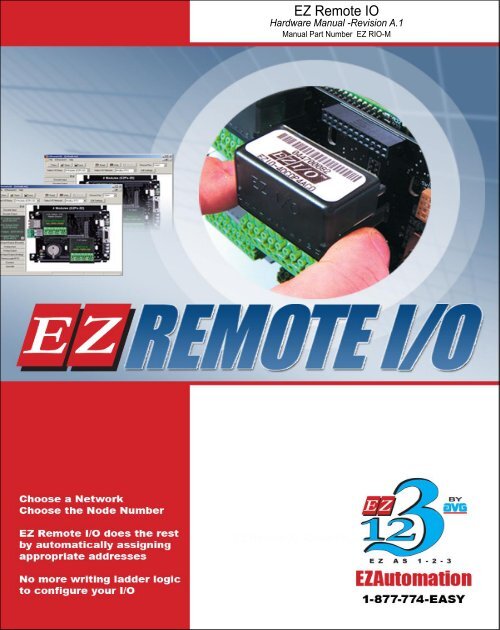
EZ Remote IO<br />
Hardware Manual -Revision A.1<br />
Manual Part Number EZ RIO-M<br />
EZ Remote IO H/W Manual -Cover<br />
EZ Remote IO -Cover Page
This page intentionally left blank.
EZ Remote IO<br />
Hardware Manual -Revision A.1<br />
Manual Part Number EZ RIO-M
WARNING<br />
WARNING!<br />
Control devices such as EZ Remote IO are not fail-safe devices and as such must not be used for stand-alone<br />
protection in any application. Unless proper safeguards are used, unwanted start-ups could result in equipment<br />
damage or personal injury. The operator must be made aware of this hazard and appropriate precautions must<br />
be taken. In addition, consideration must be given to the use of an emergency stop function that is independent<br />
of the EZ Remote IO.<br />
The diagrams and examples in this user manual are included for illustrative purposes only. The manufacturer<br />
cannot assume responsibility or liability for actual use based on the diagrams and examples.<br />
Trademarks<br />
This publication may contain references to products produced and/or offered by other companies. The product<br />
and company names may be trademarked and are the sole property of their respective owners. <strong>EZAutomation</strong><br />
disclaims any proprietary interest in the marks and names of others.<br />
Manual part number EZ RIO-M<br />
© Copyright 2007, <strong>EZAutomation</strong><br />
All Rights Reserved<br />
No part of this manual shall be copied, reproduced, or transmitted in any way without the prior written consent of<br />
<strong>EZAutomation</strong>. <strong>EZAutomation</strong> retains the exclusive rights to all information included in this document.<br />
Designed and Built by AVG<br />
4140 Utica Ridge Rd. • Bettendorf, IA 52722-1327<br />
Marketed by <strong>EZAutomation</strong><br />
4140 Utica Ridge Road • Bettendorf, IA 52722-1327<br />
Phone: 1-877-774-EASY • Fax: 1-877-775-EASY • www.<strong>EZAutomation</strong>.net<br />
EZ RIO-M
v<br />
Table of Contents<br />
EZ Remote IO H/W Manual -Cover<br />
WARNING<br />
EU Information<br />
Chapter 1 - Getting Started<br />
1.1 Introduction 1-2<br />
1.2 Purpose of the Manual 1-3<br />
1.3 EZ Remote IO System Overview 1-4<br />
1.4 EZ Remote IO Specifications 1-5<br />
1.5 Components of the EZ Remote IO System 1-7<br />
1.6 Part Numbering of the EZ Remote IO Components 1-8<br />
1.7 Quick and EZ Start to Get Familiar with EZ Remote IO 1-10<br />
Chapter 2 - Installation<br />
2.1 EZ Remote IO Mounting 2-2<br />
2.2 EZ Remote IO Base Wiring 2-7<br />
2.3 EZIO Modules Positioning 2-10<br />
2.4 EZIO Mounting and Wiring 2-12<br />
2.5 Safety Considerations 2-14<br />
2.6 Installation Considerations 2-15<br />
2.7 Electrical Considerations 2-17<br />
2.8 Sourcing (P type) and Sinking (N type) I/O 2-24<br />
Chapter 3 - DeviceNet Configuration and Installation<br />
3.1 Introduction 3-2<br />
3.2 Installation and Wiring 3-3<br />
3.3 DeviceNet Module Configuration 3-7<br />
Chapter 4 - Profibus Configuration and Installation<br />
4.1 Introduction 4-2<br />
4.2 Installation and Wiring 4-2<br />
4.3 Profibus Module Configuration 4-6<br />
Index
EU Information<br />
vi<br />
EU Information<br />
.<br />
EZ Remote IO is manufactured in compliance with European Union (EU) Directives and carries the CE mark.<br />
EZ Remote IO has been tested under CE Test Standard #EN55011, and is submitted for UL Certification.<br />
.<br />
Please Note<br />
Products with CE marks perform their required functions safely and<br />
adhere to relevent standards as specified by EU directives provided they<br />
are used according to their intended purpose and that the instructions in<br />
this manual adhere to. The protection provided by the equipment may be<br />
impaired if this equipment is not used in accordance with this manual.<br />
Only replacement parts supplied by <strong>EZAutomation</strong> or its agents should<br />
be used.<br />
Technical<br />
Support<br />
Consult EZ Remote IO Software Help or you may find answers to your<br />
questions in the operator interface section of our website @ www.<br />
<strong>EZAutomation</strong>.net. If you still need assitance, please call our technical<br />
support at 1-877-774-EASY or FAX us at 1-877-775-EASY<br />
SELV Circuits<br />
All electrical circuits connected to the communications port receptacle are<br />
rated as Safety Extra Low Voltage (SELV).<br />
Environmental<br />
Specifications<br />
Operating Temperature: -100 to +60 °C<br />
Storage Temperature: -20 to +70 °C<br />
Operating Humidity: 10 - 95% R.H., noncondensing<br />
Air Composition: No corrosive gasses permitted<br />
Preventative<br />
Maintenance<br />
and Cleaning<br />
No special preventative maintenance is required.
Chapter 1 - Getting Started 1<br />
Getting Started<br />
In this chapter....<br />
• Introduction<br />
• Purpose of the Manual<br />
- Where to get HELP - Technical Support<br />
• EZ Remote IO System Overview<br />
• EZ Remote IO Specifications<br />
• Components of the EZ Remote IO System<br />
• Part Numbering of the EZ Remote IO System<br />
• Quick and EZ Start to Getting Familiar with EZ Remote IO<br />
D R A F T
1-2 Chapter 1 - Getting Started<br />
1.1 Introduction<br />
Welcome to <strong>EZAutomation</strong>’s latest, highly flexible and cost effective EZ Remote IO<br />
System. <strong>EZAutomation</strong> is the newest addition to the AVG family, with a 37-year-old<br />
tradition of manufacturing more than 200 high value and most innovative automation<br />
products.<br />
AVG, established in 1975, is an American group of companies comprised of Autotech,<br />
Uticor, and now <strong>EZAutomation</strong>. Since its inception, AVG has introduced more than<br />
500 innovative new products, including PLS, PLCs and Remote IOs. We have more<br />
than 20 patents in Automation products and 15 new patents are pending.<br />
Uticor, formerly Struthers Dunn Systems division, has been at the forefront of PLCs,<br />
welding controls, message displays and operator interface technology since 1968.<br />
Uticor, in fact, was one of the early inventors of PLCs back in 1968. It held numerous<br />
patents on PLCs, then called Process Control Computers.<br />
The EZ Remote IO’s innovation, flexibility, cost-effectiveness and precision, comes<br />
from Uticor’s 37 years of PLCs experience.<br />
US Patent No.<br />
3,761,882 issued to<br />
Uticor on Sept 25, 1973<br />
Describing the first time use of<br />
programmable memories in PLCs
Chapter 1 - Getting Started<br />
1-3<br />
1.2 Purpose of the Manual<br />
This manual is presented with details and step-by-step information on Installation and<br />
Configuration of a new EZ Remote IO System. It also provides understanding on how to connect<br />
an EZ Remote IO with other components in your control system.<br />
This manual is a good reference guide for personnel who install as well as configure EZ Remote<br />
IO System. If you understand Remote IO in general, you can find all the information you need<br />
to start and maintain your system in this manual.<br />
Where to get HELP - Technical Support<br />
We make every effort to keep our manuals in line with the feedback from our customers. If you<br />
find it difficult to locate what you are looking for, check the resources listed below for the topic<br />
you are looking for.<br />
• Table of Contents: A listing of contents per chapter, at the beginning of manual.<br />
• Index:<br />
Index is an alphabetical listing of all key words located at the back<br />
of the manual.<br />
• Key Topics for At the begining of each chapter<br />
Each Chapter:<br />
Although most of your questions will be answered within this manual, if you still need assistance,<br />
technical support is available at 1-877-774-EASY. Our voted best Tech Support Engineers are<br />
available Monday through Friday 6 A.M. to 12 midnight CST.<br />
You can also reach us at 1-563-650-8112 on the weekends for emergency tech support. We<br />
may not be able to provide you the level of support available during the week, but we would<br />
most likely be able to solve your emergency needs.<br />
You can also visit our website for online resources and the latest product related information.<br />
Our web address is www.<strong>EZAutomation</strong>.net.<br />
Technical Support:<br />
1-877-774-EASY<br />
(Mon thru Fri)<br />
(6am-12pm CST)<br />
Weekend Emergency<br />
Technical Support:<br />
1-563-650-8112
1-4 Chapter 1 - Getting Started<br />
1.3 EZ Remote IO System Overview<br />
EZ Remote IO is an excellent way to add on a number of I/Os to any Programmable Logic Controller<br />
at an incredibly low price. Provided that the controller should be capable of communicating on any<br />
of the following networks -Modbus RTU, Modbus TCP/IP, DeviceNet or Profibus.<br />
PLC<br />
Communication Link<br />
• Modbus RTU<br />
• Modbus TCP/IP<br />
• DeviceNet<br />
• Profibus<br />
EZ Remote IO<br />
1<br />
EZ Remote IO can be added to<br />
any controller, that is capable of<br />
communicating on any of the<br />
above networks<br />
EZ Remote IO<br />
2<br />
EZ Remote IO<br />
n<br />
EZ Remote IO bases :<br />
-Available in four models 4, 6, 8 or 12 slots<br />
-Respectively 32, 48, 64 or 96 I/O points<br />
-Either 24 VDC or 110 VAC power input<br />
-EZ Remote IO has a built-in RS232 port, RS-422 port<br />
-Optional communication cards for DeviceNet Slave and Profibus Slave<br />
-Enhanced model comes with additional Ethernet connectivity
Chapter 1 - Getting Started<br />
1-5<br />
1.4 EZ Remote IO Specifications<br />
Part Number<br />
EZ RIO-A-32 - Standard<br />
EZ RIO-A-32E - Ethernet<br />
EZ RIO-D-32 - Standard<br />
EZ RIO-D-32E - Ethernet<br />
EZ Remote IO Base Specifications<br />
EZ RIO-A-48 - Standard<br />
EZ RIO-A-48E - Ethernet<br />
EZ RIO-D-48 - Standard<br />
EZ RIO-D-48E - Ethernet<br />
EZ RIO-A-64 - Standard<br />
EZ RIO-A-64E - Ethernet<br />
EZ RIO-D-64 - Standard<br />
EZ RIO-D-64E - Ethernet<br />
EZ RIO-A-96 - Standard<br />
EZ RIO-A-96E - Ethernet<br />
EZ RIO-D-96 - Standard<br />
EZ RIO-D-96E - Ethernet<br />
Specifications<br />
Input Voltage Range<br />
Maximum I/O<br />
Capacity<br />
Power Supply<br />
Capacity<br />
CPU & Support<br />
Electronics Power<br />
I/O Module Power<br />
(typical)<br />
DeviceNet/Profibus<br />
Interface Power<br />
Maximum Power<br />
Consumption<br />
CPU Processor<br />
LED Indicators<br />
I/O Supported<br />
Operating<br />
Temperature<br />
Storage<br />
Temperature<br />
Humidity<br />
Electrical Noise<br />
Agency Approval<br />
Withstand Voltage<br />
Insulation<br />
Resistance<br />
Vibration<br />
Shock<br />
Protocols<br />
Supported<br />
4 Slot EZ RIO<br />
AC Powered<br />
110 VAC<br />
(95-125VAC)<br />
4 Slot EZ RIO<br />
DC Powered<br />
24VDC<br />
(20-28VDC)<br />
EZ Remote IO models with “E” suffix are built with 10/100 Base-T Ethernet with a standard RJ45 connector<br />
6 Slot EZ RIO<br />
AC Powered<br />
110 VAC<br />
(95-125VAC)<br />
6 Slot EZ RIO<br />
DC Powered<br />
24VDC<br />
(20-28VDC)<br />
8 Slot EZ RIO<br />
AC Powered<br />
110 VAC<br />
(95-125VAC)<br />
8 Slot EZ RIO<br />
DC Powered<br />
24VDC<br />
(20-28VDC)<br />
12 Slot EZ RIO<br />
AC Powered<br />
110 VAC<br />
(95-125VAC)<br />
12 Slot EZ RIO<br />
DC Powered<br />
24VDC<br />
(20-28VDC)<br />
4 Slot Base (32I/O Max) 6 Slot Base (48I/O Max) 8 Slot Base (64I/O Max) 12 Slot Base (96I/O Max)<br />
3.3V @ 1 Amp<br />
300mA<br />
25mA<br />
DeviceNet 50mA<br />
Profibus 100mA<br />
10 watts 11 watts 12 watts 15 watts<br />
32 Bit, 40 MHz RISC Processor<br />
Input Power and CPU Status (Run) active indicators<br />
EZI/O Snap-in modules with status LEDs and Removable Terminal Block<br />
DC / AC / Analog / Relay / Thermocouple / High Speed Counter / DeviceNet / Profibus<br />
-10C to 60C<br />
-20C to 70C<br />
10-95% Non-Condensing<br />
Nema ICS 2-230 Showering arc; ANSI C37.90a SWC; Level C Chattering Relay Test (pending)<br />
UL, CUL, CE (pending)<br />
1000VDC (1 minute) between power supply input terminal and protective ground)<br />
Over 20M Ohm between power supply input and terminal and protective ground<br />
5 to 55Hz 2G’s for 2 hours in X,Y,and Z axis<br />
10G for under 12ms in the X,Y, and Z axis<br />
Modbus RTU, Modbus TCP/IP, DeviceNet , Profibus<br />
Communication<br />
Ports<br />
Standard Model: Port 1: RS232<br />
Port 2: RS422<br />
Ethernet Model: Port 1: RS232<br />
Port 2: RS422<br />
Port 3: Ethernet<br />
External<br />
Dimensions<br />
5.75” x 4.868” x 3.124”<br />
(146.05 x 123.65 x 79.356mm)<br />
8.35” x 4.868” x 3.124”<br />
(212.09 x 123.65 x 79.356mm)<br />
9.21” x 5.818” x 3.124”<br />
(233.93 x 147.78 x 79.356mm)<br />
14.908” x 5.173” x 3.124”<br />
(378.65 x 131.4 x 79.356mm)
1-6 Chapter 1 - Getting Started<br />
EZ I/O Module Specifications-<br />
For the EZ I/O Module Specifications pls refer the EZI/O Manual or you may view the specifications in the<br />
EZRemote IO Software itself.<br />
To view the Specification Sheet for an EZI/O Module in the Software, you have got two options:<br />
1. Right-Click on the EZI/O Module Selection List.<br />
2. Place the EZI/O module on the EZRemote IO base and then Right-Click on it.<br />
1. Right-Click on the EZI/O Module Selection List<br />
2. Place the EZI/O module on the EZRemote IO base and then Right-Click on it
Chapter 1 - Getting Started<br />
1-7<br />
1.5 Components of the EZ Remote IO System<br />
Configuration S/W<br />
1<br />
EZ RIO<br />
Cable<br />
2<br />
EZ Remote IO Base<br />
3<br />
EZ IO Modules<br />
5<br />
DeviceNet<br />
Profibus<br />
Communication Options<br />
Communication<br />
4<br />
DeviceNet 5 Pin<br />
Field Terminal Block<br />
Modbus RTU -Any standard EZ Remote IO base model<br />
Modbus TCP/IP -Any Enhanced EZ Remote IO base model<br />
with Ethernet Option<br />
DeviceNet -An Optional DeviceNet Communication<br />
Module will be required along with the<br />
EZ Remote IO Base<br />
Profibus -An Optional Profibus Communication<br />
Module will be required along with the<br />
EZ Remote IO Base<br />
5 Pin Terminal Block<br />
11 Pin Terminal Block<br />
Dummy Module<br />
Accessories<br />
6<br />
Note: Cables to connect to the networks have not been shown here.
1-8 Chapter 1 - Getting Started<br />
1.6 Part Numbering of the EZ Remote IO<br />
1<br />
2<br />
3<br />
Configuration Software<br />
EZ RIO-EDIT Software allows to configure the EZ Remote IO (one time purchase)<br />
Cable<br />
EZ PGMCBL Cable to connect the PC and Remote IO Base for EZ Remote IO<br />
configuration (one time purchase)<br />
EZ Remote IO Base<br />
Part Numbering System of the EZ Remote IO Base<br />
EZ RIO - X - XX - X<br />
Max I/O Supported<br />
4 Slots Base: 32 I/O Max 32<br />
Power Input<br />
6 Slots Base: 48 I/O Max 48<br />
110VAC<br />
A<br />
8 Slots Base: 64 I/O Max 64<br />
Enhanced<br />
24VDC<br />
D<br />
12 Slots Base: 64 I/O Max 96<br />
Built-in Ethernet TCP/IP<br />
E<br />
Example EZ RIO-D-32-E EZ Remote IO base with DC power, 32 I/Os and Ethernet option<br />
Following is the list of EZ Remote IO Base Part Numbers :<br />
Part Number EZ Remote IO Base Description<br />
EZ RIO-A-32 4-slot EZ Remote IO AC Powered; 32 I/O Max<br />
EZ RIO-A-32-E 4-slot EZ Remote IO AC Powered; 32 I/O Max; with built-in Ethernet<br />
EZ RIO-D-32 4-slot EZ Remote IO DC Powered; 32 I/O Max<br />
EZ RIO-D-32-E 4-slot EZ Remote IO DC Powered; 32 I/O Max; with built-in Ethernet<br />
EZ RIO-A-48 6-slot EZ Remote IO AC Powered; 48 I/O Max<br />
EZ RIO-A-48-E 6-slot EZ Remote IO AC Powered; 48 I/O Max; with built-in Ethernet<br />
EZ RIO-D-48 6-slot EZ Remote IO DC Powered; 48 I/O Max<br />
EZ RIO-D-48-E 6-slot EZ Remote IO DC Powered; 48 I/O Max; with built-in Ethernet<br />
EZ RIO-A-64 8-slot EZ Remote IO AC Powered; 64 I/O Max<br />
EZ RIO-A-64-E 8-slot EZ Remote IO AC Powered; 64 I/O Max; with built-in Ethernet<br />
EZ RIO-D-64 8-slot EZ Remote IO DC Powered; 64 I/O Max<br />
EZ RIO-D-64-E 8-slot EZ Remote IO DC Powered; 64 I/O Max; with built-in Ethernet<br />
EZ RIO-A-96 12-slot EZ Remote IO AC Powered; 96 I/O Max<br />
EZ RIO-A-96-E 12-slot EZ Remote IO AC Powered; 96 I/O Max; with built-in Ethernet<br />
EZ RIO-D-96 12-slot EZ Remote IO DC Powered; 96 I/O Max<br />
EZ RIO-D-96-E 12-slot EZ Remote IO DC Powered; 96 I/O Max; with built-in Ethernet
Chapter 1 - Getting Started<br />
1-9<br />
4<br />
5<br />
Communication Options<br />
EZRIO-DEVICENET<br />
EZRIO-PROFIBUS<br />
Optional DeviceNet Module<br />
Optional Profibus Module<br />
EZ I/O Modules<br />
Example EZIO-8DCI 8 point DC Inputs (sink/source)<br />
Following is the list of a variety of EZIO Part Numbers :<br />
EZ I/O Modules<br />
DC Modules<br />
EZIO-8DCI<br />
EZIO-8DCOP<br />
EZIO-8DCON<br />
EZIO-8HSDCI<br />
EZIO-4DCI4DCON<br />
EZIO-4DCI4DCIF<br />
EZIO-4DCI4DCOP<br />
AC Modules<br />
EZIO-8ACI<br />
EZIO-8ACO<br />
EZIO-4ACI4ACO<br />
AC/DC Combo Modules<br />
EZIO-4DCOP4ACO<br />
EZIO-4ACI4DCOP<br />
EZIO-4DCI4ACO<br />
Analog Modules<br />
EZIO-8ANIV<br />
EZIO-8ANIC<br />
EZIO-4ANI4ANOV<br />
EZIO-4ANI4ANOC<br />
Relay Modules<br />
EZIO-4IORLO<br />
EZIO-4ACI4RLO<br />
EZIO-4DCOP4RLO<br />
Specialty Modules<br />
EZIO-4HSCM1<br />
EZIO-4HSCM2<br />
EZIO-4THI<br />
EZIO-4THIE<br />
EZIO-4RTD<br />
8 point DC Inputs (sink/source)<br />
8 point DC (source) Outputs<br />
8 point DC (sink) Outputs<br />
8 point High Speed DC Inputs (sink/source)<br />
4 point DC (sink/source) Inputs; 4 point DC (sink) outputs<br />
4 point DC (sink/source) Inputs; 4 point High Speed DC (sink/<br />
source) Inputs<br />
4 point DC (Sink/Source) Inputs; 4 point DC (source) outputs<br />
8 point AC Inputs<br />
8 point AC Outputs<br />
4 point AC Inputs; 4 point AC Outputs<br />
4 point DC (source) Outputs; 4 point AC outputs<br />
4 point AC Inputs; 4 point DC (source) outputs<br />
4 point DC (sink/source) Inputs; 4 point AC Outputs<br />
8 channel Analog Input module (Voltage)<br />
8 channel Analog Input module (Current)<br />
4 Channel Analog Inputs; 4 Channel Analog Outputs<br />
4 Channel Analog Inputs; 4 Channel Analog Outputs<br />
4 point Relay Outputs<br />
4 point AC Inputs; 4 point Relay Outputs<br />
4 point DC (sink/source) Outputs; 4 point Relay Outputs<br />
High Speed 24-Bit Counter Module<br />
High Speed 24-Bit Counter Module<br />
4 Channel Thermocouple Input Module<br />
4 Channel Enhanced Thermocouple Input Module<br />
4 Channel RTD Input Module<br />
6 Accessories<br />
EZIO-DUMMY Dummy Module for Open Slots<br />
EZIO-TERM11 11 Pin Removeable 3.5mm Phoenix Terminal Block<br />
EZPLC-TERM5 5 Pin Removable 3.5mm Phoenix Terminal Block<br />
EZPLC -DNTERM5 DeviceNet 5Pin Field Terminal Block
1-10 Chapter 1 - Getting Started<br />
1.7 Quick and EZ Start to Get Familiar with EZ Remote IO<br />
1.7 Quick and EZ Start to Get Familiar with<br />
EZ Remote IO<br />
In this section we present a quick example of how you can setup your EZ Remote<br />
IO. You will see how EZ it is to setup an EZ Remote IO, even if you are new to<br />
Remote IOs. This example is not intended to explain specific details needed to<br />
start-up your system. Rather, it provides a quick guide to give a broad picture of<br />
what is needed to power-up your EZ Remote IO system.<br />
Step 1 Check all System Components<br />
It is always recommended to make sure you have all the right parts<br />
to build your system.<br />
Step 2 Install I/O Modules<br />
Insert EZIO module(s) into the base. EZIO modules have a snap-on<br />
design to facilitate easy installation and removal from the base slots.<br />
The I/O modules have two clips and a Molex connector, which snap into<br />
the EZ Remote IO Base.<br />
• Hold the module in the thumb and index finger so that your fingertips<br />
are on the clips (see image to the left)<br />
• Snap the module onto the board so that clips are placed on the open<br />
slots<br />
• Make sure that the Molex connector is aligned to the female counter<br />
part on the base<br />
• Push the module gently from the top to insert it completely until<br />
you hear a clicking sound<br />
Step 3 Connect Power<br />
Connect the power input wires into the EZ Remote IO’s power<br />
terminals. Do not apply power at this time.<br />
Step 4 Install software on your PC<br />
Load the CD included with the purchase of software (P/N EZRIO-EDIT)<br />
into your computer’s CD-ROM drive and follow the on-screen<br />
instructions. The software will install itself.<br />
N OTE: If y o u<br />
p u r c h a s e d a n<br />
AC Power Base,<br />
everything else remains<br />
the same except for the<br />
use of 110 VAC in place<br />
of 24 VDC.<br />
Step 5 Connect EZ Remote IO to your PC<br />
Connect your PC’s serial port to EZ Remote IO’s RS232 port using the<br />
programming cable (P/N EZP-PGMCBL).<br />
Step 6 Switch ON the Power<br />
Apply power to the system and ensure the PWR indicator LED on the<br />
EZ Remote IO base is ON. If not, remove power from the system and<br />
check all wiring.
Chapter 1 - Getting Started<br />
1-11<br />
Step 7 Create and Transfer a Configuration Project<br />
The EZ Remote IO application configures the Remote IO system<br />
by following the steps given below:<br />
1. Select the I/O Base<br />
2. Select the Network Type<br />
3. Place the module(s) onto the base<br />
4. Choose the communication port<br />
5. Transfer the configuration project to EZ Remote IO<br />
Congratulations!<br />
You have successfully configured your EZ Remote IO.
Chapter 2 - Installation<br />
2<br />
Installation<br />
In This Chapter....<br />
• EZ Remote IO Mounting<br />
-Base Mounting Dimensions<br />
• EZ Remote IO Base Wiring<br />
• EZIO Modules Positioning<br />
• EZIO Mounting and Wiring<br />
• Safety Considerations<br />
• Installation Considerations<br />
-General Environmental Considerations<br />
-Environmental Specifications<br />
-Agency Approvals<br />
-Physical Control Panel Layout<br />
• Electrical Considerations<br />
-Understanding of Electrical Noise,<br />
Optical Isolation, Wiring and Shielding<br />
-Cabinet Grounding<br />
-Cabinet Wiring<br />
-AC/DC Transient Protection<br />
-Filtering AC Line Noise<br />
-Isolating DC Power Supplies<br />
• Sourcing/Sinking Concepts<br />
D R A F T
2-2<br />
Chapter 2 - Installation<br />
2.1 EZ Remote IO Mounting<br />
2.1 EZ Remote IO Mounting<br />
Safety is the most important element of a proper system installation. Adhering to these safety<br />
considerations ensures the safety of yourself and others, as well as the condition of your equipment.<br />
We recommend reviewing the following safety considerations:<br />
1) Disconnecting Main Power<br />
2) Safety Circuits<br />
3) Fail-Safe Operation<br />
Please follow all applicable local and national codes to ensure maximum safety of the equipment<br />
and personnel. The installation and operational environment must be maintained per the latest<br />
revision of these codes. You are responsible to determine the codes to be followed, and to verify<br />
the compliance of equipment, installation, and operation with the latest revision of these codes.<br />
Safety issues have also been discussed in detail in the later part of this chapter.<br />
Mounting Dimensions<br />
The diagrams on the following pages provide exact Base dimensions. The dimensions here<br />
represent the EZ Remote IO bases with I/O modules installed on them. However, it should<br />
be noted that EZ Remote IO offers flexibility to design your system based on your specific I/O<br />
requirements. So EZIO modules have to be purchased separately. EZIO has a snap-on design<br />
so that the I/O modules can be installed on the Base easily either before or after mounting the<br />
EZ Remote IO base.<br />
There is no limitation on I/O module location, except:<br />
1. The bottom left module cannot be AC Output or Relay module.<br />
2. Analog input and output combination module can be configured only in the first 4 slots.<br />
3. All Analog or Specialty modules can be configured only in the first 10 slots.<br />
Use 4/6 screws with STAR washers to secure the unit to the mounting surface.<br />
Pls refer to the table EZ I/O Module Position Restriction on the page 2-11 of this chapter.<br />
Dimensions of the EZ Remote IO bases are provided on the following pages, in inches and<br />
millimeters, mm appear in brackets [ ].
Chapter 2 - Installation 2-3<br />
EZ Remote IO base -4 Slots (32 I/O Model)<br />
Models:<br />
EZ RIO-A-32<br />
EZ RIO-A-32-E<br />
EZ RIO-D-32<br />
EZ RIO-D-32-E
2-4<br />
Chapter 2 - Installation<br />
EZ Remote IO base -6 Slots (48 I/O Model)<br />
Models:<br />
EZ RIO-A-48<br />
EZ RIO-A-48-E<br />
EZ RIO-D-48<br />
EZ RIO-D-48-E
Chapter 2 - Installation 2-5<br />
EZ Remote IO base -8 Slots (64 I/O Model)<br />
Models:<br />
EZ RIO-A-64<br />
EZ RIO-A-64-E<br />
EZ RIO-D-64<br />
EZ RIO-D-64-E
2-6<br />
Chapter 2 - Installation<br />
EZ Remote IO base -12 Slots (96 I/O Model)<br />
Models:<br />
EZ RIO-A-96<br />
EZ RIO-A-96-E<br />
EZ RIO-D-96<br />
EZ RIO-D-96-E
Chapter 2 - Installation 2-7<br />
2.2 EZ Remote IO Base Wiring<br />
Power Input<br />
24 Volts DC<br />
110 Volts AC<br />
Com1 Port<br />
Use the cable<br />
# EZ PGMCBL<br />
to configure the<br />
EZ Remote IO<br />
EZ Remote IO Base<br />
Enhanced EZ Remote IO base with 4-slots and maximum 32 I/O points<br />
DC AC<br />
L1<br />
L2<br />
+ -<br />
EZ RIO<br />
Power, CPU LEDs<br />
Slots<br />
(to place EZ I/O Modules)<br />
Ethernet Port<br />
(for Modbus TCP/IP network)<br />
(Only on EZ Remote IO base<br />
models with Ethernet Option)<br />
for DeviceNet Communication Option<br />
-Pls refer to the Chapter-3<br />
for Profibus Communication Option<br />
-Pls refer to the Chapter-4<br />
RS422 Port<br />
(for Modbus RTU network)<br />
Power Connection<br />
Power, CPU LEDs<br />
LED Color Comment<br />
PWR On (Red) Power is ON<br />
Off<br />
No Power to Unit<br />
CPU On (Green) CPU is scanning I/O<br />
Off<br />
CPU is NOT scanning I/O<br />
One of the two reasons:<br />
1. I/O may not be configured<br />
(Check the configuration by<br />
reading back from the unit)<br />
2. Hardware problem
2-8<br />
Chapter 2 - Installation<br />
COM1 Port<br />
Pin Function<br />
2 TXD<br />
3 RXD<br />
5 GND<br />
9-Pin Sub-D<br />
Shield<br />
PC COM Port<br />
Pin Function<br />
2 RXD<br />
3 TXD<br />
5 GND<br />
9-Pin Sub-D<br />
Shield connected to<br />
Earth Ground on both sides<br />
RS232 Wiring Diagram<br />
* Terminal 1 is Logic Common<br />
DO NOT CONNECT TO PIN #1<br />
RS422 Wiring Diagram<br />
*<br />
SD-<br />
SD+<br />
RD+ 4<br />
RD-<br />
Shield connected to<br />
Earth Ground on both sides<br />
1<br />
2<br />
3<br />
5<br />
EZ Remote IO
Chapter 2 - Installation 2-9<br />
EZ Remote IO 1<br />
RS422 Port<br />
1 2 3 4 5<br />
GND SD- SD+ RD+ RD-<br />
EZ Remote IO 2<br />
RS422 Port<br />
1 2 3 4 5<br />
GND SD- SD+ RD+ RD-<br />
EZ Remote IO n<br />
RS422 Port<br />
1 2 3 4 5<br />
GND SD- SD+ RD+ RD-<br />
C<br />
O<br />
N<br />
T<br />
R<br />
O<br />
L<br />
L<br />
E<br />
R<br />
SD+<br />
SD-<br />
RD+<br />
RD-<br />
Modbus RTU Wiring<br />
EZ Remote IO 1<br />
EZ Remote IO 2<br />
EZ Remote IO n<br />
Ethernet Port<br />
Ethernet Port<br />
Ethernet Port<br />
C<br />
O<br />
N<br />
T<br />
R<br />
O<br />
L<br />
L<br />
E<br />
R<br />
Hub/Switch/Router<br />
Ethernet Connectivity
2-10<br />
Chapter 2 - Installation<br />
2.3 EZIO Modules Positioning<br />
Slots Numbering System<br />
As discussed earlier there are 4 bases you can choose from: 4 slots, 6 slots, 8<br />
slots and 12 slots, that can support up to a maximum of 32, 48, 64 and 96 I/O<br />
points respectively. Use the following conventions to identify the slot numbers<br />
on the bases.<br />
CAUTION! The M2 slot<br />
cannot be used for any<br />
AC or Relay output module.<br />
Also, modules with<br />
both Analog inputs and<br />
outputs can be used only<br />
on slots M1 through M4<br />
and Analog and Counter<br />
modules in general must<br />
be used from M1 through<br />
M10.<br />
You can directly select an EZIO module and place it on a desired slot of the EZ<br />
Remote IO Base in the EZ Remote IO Software itself. The picture above shows<br />
the I/O module positioning convention employed in EZ Remote IO. Following<br />
are the guidelines/recommendations for installing I/O modules on an EZ Remote<br />
IO base. We have shown and described the 12-slots (capable of 96 I/O points<br />
MAX) base here; however the module numbering convention as well as the<br />
positioning guidelines remain the same for smaller bases.
Chapter 2 - Installation 2-11<br />
EZ I/O Module Position Restrictions<br />
EZ I/O Modules<br />
DC Modules<br />
EZIO-8DCI<br />
EZIO-8DCOP<br />
EZIO-8DCON<br />
EZIO-8HSDCI<br />
EZIO-4DCI4DCON<br />
EZIO-4DCI4DCIF<br />
EZIO-4DCI4DCOP<br />
AC Modules<br />
8 point DC Inputs (sink/source)<br />
8 point DC (source) Outputs<br />
8 point DC (sink) Outputs<br />
8 point High Speed DC Inputs (sink/source)<br />
4 point DC (sink/source) Inputs; 4 point DC (sink) outputs<br />
4 point DC (sink/source) Inputs; 4 point High Speed DC (sink/source) Inputs<br />
4 point DC (Sink/Source) Inputs; 4 point DC (source) outputs<br />
Recommendations for<br />
Positioning of Modules<br />
Any Slot<br />
EZIO-8ACI 8 point AC Inputs Any Slot<br />
Any Slot Except M2<br />
(will not fit over battery)<br />
EZIO-8ACO 8 point AC Outputs Any Slot Between M1 and M10 Except M2<br />
EZIO-4ACI4ACO 4 point AC Inputs; 4 point AC Outputs Any Slot Except M2<br />
AC/DC Combo Modules<br />
EZIO-4DCOP4ACO 4 point DC (source) Outputs; 4 point AC outputs Any Slot Except M2<br />
EZIO-4ACI4DCOP 4 point AC Inputs; 4 point DC (source) outputs Any Slot Except M2<br />
EZIO-4DCI4ACO 4 point DC (sink/source) Inputs; 4 point AC Outputs Any Slot Except M2<br />
Analog Modules<br />
EZIO-8ANIV<br />
EZIO-8ANIC<br />
EZIO-4ANI4ANOV<br />
EZIO-4ANI4ANOC<br />
Relay Modules<br />
EZIO-4IORLO<br />
EZIO-4ACI4RLO<br />
EZIO-4DCOP4RLO<br />
Specialty Modules<br />
8 channel Analog Input module (Voltage)<br />
8 channel Analog Input module (Current)<br />
4 Channel Analog Inputs; 4 Channel Analog Outputs<br />
4 Channel Analog Inputs; 4 Channel Analog Outputs<br />
4 point Relay Outputs<br />
4 point AC Inputs; 4 point Relay Outputs<br />
4 point DC (sink/source) Outputs; 4 point Relay Outputs<br />
Any Slot Between M1 and M10 Except M2<br />
Any Slot Between M1 and M4 Except M2<br />
Any Slot Between M1 and M10 Except M2<br />
EZIO-4HSCM1 High Speed 24-Bit Counter module Any Slot Between M1 and M10 Except M2<br />
EZIO-4HSCM2 High Speed 24-Bit Counter module<br />
3 Modules Max per Base<br />
EZIO-4THI 4 Channel thermocouple input module Any Slot Between M1 and M10 Except M2<br />
EZIO-4THIE Enhanced Thermocouple Module Any Slot from M1 to M10<br />
EZIO-4RTD Resistance Temperature Detector Any Slot from M1 to M10
2-12<br />
Chapter 2 - Installation<br />
2.4 EZIO Mounting and Wiring<br />
EZIO Installation Overview<br />
EZIO modules are designed with one thing in mind - modularity! Any base of<br />
EZ Remote IO can be fitted with each and every EZIO module. All EZ Family<br />
Remote IOs are designed to handle any combination of EZIO modules without<br />
any need for power budgeting. Most EZIO modules consume only 20-40 mA<br />
current at 3.3V.<br />
Mounting I/O Modules<br />
EZIO modules have a snap-on design to facilitate easy installation and removal<br />
from the base slots. The I/O modules have two clips and a Molex connector,<br />
which snap into EZ Remote IO Base.<br />
EZIO Module Dimensions<br />
STEP 1<br />
STEP 1 - Hold the module in the<br />
thumb and index finger so that your<br />
fingertips are on the clips.<br />
STEP 2<br />
STEP 2 - Snap the module<br />
on the board so that clips are<br />
placed on the open mounting<br />
slots. Make sure that the<br />
Molex connector is aligned<br />
to the female counterpart<br />
on the base. Push the<br />
module gently from the top<br />
to insert it completely until<br />
you hear a clicking sound.<br />
Molex<br />
connector<br />
Mounting<br />
slot<br />
Wiring EZIO Modules<br />
As shown in the picture, simply insert the wire and screw to tighten. You can<br />
wire up to ONE 14 AWG wire, TWO 18 AWG wires, or FOUR 22 AWG wires in<br />
every terminal. You will need a 2.5mm blade screwdriver (P/N EZIO-SCDRV)<br />
to work with the EZIO terminal blocks and wiring.<br />
Routing EZIO Wiring<br />
EZIO modules have wiring trays for proper routing of field wires.
Chapter 2 - Installation 2-13<br />
Number of Wires<br />
Allowed in Each Terminal<br />
1 14 AWG<br />
2 18 AWG<br />
4 22 AWG<br />
Wiring Capabilities<br />
UL rated at 300 volts,<br />
10 amps 14 AWG<br />
Discrete I/O Module Status Indicators<br />
The discrete I/O modules have LED status indicators to<br />
provide visual indication of the input points activity.<br />
Removable Terminal Blocks<br />
EZIO eliminates the need for rewiring your<br />
terminal block anytime you need to swap a<br />
module. Since these modules are built to<br />
withstand industrial environments, terminal<br />
blocks fit very snugly on the module. Slip the<br />
edge of the screwdriver under the terminal<br />
block and lift to pop it off.<br />
Removing I/O Modules<br />
- Hold the module in the thumb and index finger so that your<br />
fingertips are on the clips.<br />
- Apply inward pressure on the two clips with your fingers to<br />
release the module from the mounting slots on the base.<br />
- Pull the module out.
2-14<br />
Chapter 2 - Installation<br />
2.5 Safety Considerations<br />
Please follow all applicable local and national codes to ensure maximum<br />
safety of the equipment and personnel. The installation and operational<br />
environment must be maintained per the latest revision of these codes.<br />
You are responsible to determine the codes to be followed, and to verify<br />
the compliance of equipment, installation, and operation with the latest<br />
revision of these codes.<br />
Plan for Safety<br />
It is an absolute must to follow all applicable sections of:<br />
• The National Fire Code<br />
• The National Electrical Code (NEC)<br />
• The National Electrical Manufacturer’s Association (NEMA) codes.<br />
Local regulatory and government offices usually provide excellent help to<br />
determine which codes and standards are necessary for safe installation<br />
and operation.<br />
Safety Techniques<br />
Safety is the most important element of a proper system installation. Adhering<br />
to these safety considerations ensures the safety of yourself and others,<br />
as well as the condition of your equipment. We recommend reviewing the<br />
following safety considerations:<br />
1) Disconnecting Main Power<br />
The main power switch should be easily accessible to the operators<br />
and maintenance personnel. It is important to make sure that all other<br />
sources of power including pneumatic and hydraulic are de-energized<br />
before starting the work on a machine or process controlled by a<br />
Remote IO.<br />
2) Safety Circuits<br />
Most of the machines are installed with safety circuits, like Limit<br />
switches, Emergency stop push buttons, and Interlocks. These circuits<br />
should always be hard-wired directly to the Remote IO. These devices<br />
must be wired in series so that when any one device opens, the Remote<br />
IO is automatically de-energized. This removes power to the machine.<br />
These circuits should not be altered in any case, since serious injury<br />
or machine damage could result.<br />
3) Fail-Safe Operation<br />
Our products are not fault-tolerant and are not designed or intended<br />
for use as on-line control equipment in hazardous environments requiring<br />
fail-safe performance, such as in operation of nuclear facilities,<br />
aircraft navigation or communication systems, air traffic control, direct<br />
life-support machines, weapons systems, clutch control systems on<br />
presses, in which the failure of the product could lead directly to death,<br />
personal injury or severe physical or environmental damage. External<br />
fail safe and/or redundant components are required to make your<br />
control system Fail-safe.
Chapter 2 - Installation 2-15<br />
2.6 Installation Considerations<br />
<strong>EZAutomation</strong> products have been designed and tested for operation in the most demanding<br />
industrial environments. Modern solid-state industrial controls are complex electronic<br />
equipment that operate at low levels of voltage and current, coexisting with components that<br />
operate at much higher levels of power. The difference in operating power characteristics<br />
between the high and low power control devices creates the possibility of unwanted signals<br />
being generated causing interference. The interference, which is a by-product of electrical<br />
noise, is not present at all times. However, it appears at random and during brief periods<br />
of time it can cause disruptions and errors in the operation of a control system.<br />
Enhancement of a system’s noise level immunity, and its tolerance to other environmental<br />
hazards can be accomplished by following proper system installation guidelines. The<br />
recommendations are of a general nature and constitute good industrial installation<br />
practice.<br />
General Environmental Installation Considerations<br />
Avoid installing EZ Remote IO in areas where the following conditions may exist:<br />
• Environmental temperatures above or below those specified by the EZ Remote IO<br />
• Prolonged exposure to humidity and liquids which may be sprayed or splashed on the<br />
equipment<br />
• Dusty environments where airborne particles may accumulate on equipment causing<br />
reduction of heat dissipation, and reduction in effective electrical spacing between<br />
components<br />
• Areas of excessive vibration<br />
• Areas of high-radiated electrical noise, such as near fields of transmitting antennas<br />
and areas in close proximity of arc welding stations<br />
Environmental Specifications<br />
The following table lists the environmental specifications that generally apply to the<br />
EZ Remote IO Bases and EZIO modules. Please refer to the appropriate I/O module<br />
specifications in the EZIO User Manual (P/N EZIO-M).<br />
Parameter<br />
Operating Temperature -10 to 60 °C<br />
Storage Temperature -20 to 70 °C<br />
Humidity<br />
Vibration Resistance<br />
Shock Resistance<br />
Electrical Noise<br />
Atmospheric Conditions<br />
Ratings<br />
10 to 95% Relative Humidity, Non-condensing<br />
5 to 55 Hz, 2g for 2 Hours in X, Y, and Z Axes<br />
10g for under 12 ms in X, Y, and Z Axes<br />
NEMA ICS 2-230 Showering Arc, ANSI C37.90a SWC, Level C<br />
Chattering Test<br />
Non-corrosive gases
2-16<br />
Chapter 2 - Installation<br />
Agency Approvals<br />
Your application may require Agency approval*. EZ Remote IO’s agency<br />
approvals are:<br />
• UL (Underwriter’s Laboratories, Inc)*<br />
• CUL (Canadian Underwriter’s Laboratories, Inc)*<br />
• CE (EU Certification)*<br />
• Approvals in process. Check our website www.<strong>EZAutomation</strong>.net for the<br />
latest information.<br />
Remote<br />
IO<br />
Physical Layout of EZ Remote IO In Control Cabinets<br />
When possible, cabinets housing electronic equipment should be designed with<br />
provisions for natural or forced ventilation to facilitate heat dissipation. Observe<br />
the following rules for cabinet installation:<br />
• Heat generating equipment (power supplies and other heat inducing<br />
components) should be installed toward the top of the cabinet. The lower<br />
space in the cabinet is cooler than the top area.<br />
• Install heat-sensitive components in the lower section.<br />
• Provide enough space between components to allow a free flow of air<br />
for better heat dissipation.<br />
• Provide the maximum possible physical separation between solid state<br />
and electromechanical controls. If possible, the electro mechanical<br />
controls (motors, starters, solenoids, etc.) should be housed separately<br />
or at the farthest point when enclosed within the cabinet.<br />
We recommend that the EZ Remote IO has a minimum clear space of 2” on<br />
all sides.
Chapter 2 - Installation 2-17<br />
2.7 Electrical Considerations<br />
Understanding Electrical Noise, Optical Isolation, and<br />
Shielding of Cables<br />
This section will provide you with a very basic understanding of Electrical Noise<br />
and how to keep it away from CPUs.<br />
1. Source of Electrical Noise<br />
Industrial plants that have a number of generators of electrical noise are<br />
sometimes also referred to as Radio Frequency Interference or RFI.<br />
Any time an inductive load like a motor, motor starter, or solenoid is turned<br />
off, it generates a burst of excess energy that has to flow back to ground,<br />
just like electrical energy from a lightening storm has to flow back to Earth.<br />
Other sources are RF Welders or Radio Transmitters. RFI is short bursts<br />
of electrical energy at very high frequencies.<br />
2. Effect of RFI on Electronic Automation Equipment<br />
Electronic controls use faster and faster CPUs today. These CPUs are<br />
also operating at 2.5V to 5VDC logic level power supply. A CPU under<br />
this environment loses its brain and behaves erratically. A smart indus<br />
trial-grade CPU like the EZ Remote IO’s Card Engine, when faced with<br />
RFI, halts its operation instead of giving false outputs.<br />
3. How to Keep RFI Isolated from CPUs<br />
Cabinets<br />
Equipment cabinets usually incorporate one or two doors and/or hinged cabinet<br />
panels. In addition, sub-panels may be utilized on those electronic controls and<br />
electromechanical items that are mounted.<br />
The goal here is to create a medium for mounting the equipment and ensure<br />
grounding of the control’s chassis to it. Relying on door hinges and swinging<br />
panels for a good metallic bond between hinged parts and the main body of<br />
the cabinet does not insure adequate grounding. That is why the use of ground<br />
straps is recommended.<br />
RFI enters electronic controls in two ways:<br />
• Radiated RFI<br />
• Conducted RFI<br />
For most practical purposes, electronic devices, unless sitting right next to a<br />
powerful RFI transmitter, will not be affected by noise because air space severely<br />
attenuates such interference. On the other hand, conducted RFI travels<br />
over conductive surfaces such as power supply wires, electrical wiring of field<br />
devices, and worst of all; improper ground planes.
2-18<br />
Chapter 2 - Installation<br />
Transformer or<br />
Choke Isolation<br />
Optical Isolation<br />
Remote IO<br />
Logic Level inside Dotted Lines<br />
Power Input<br />
Filter<br />
EZ Remote<br />
IO<br />
Power<br />
Supply<br />
CPU<br />
Card<br />
Engine<br />
Motherboard<br />
at Logic<br />
Level<br />
I/O<br />
Module<br />
I/O<br />
Module<br />
Transformer or<br />
Choke Isolation<br />
PC<br />
Optical Isolation<br />
It is a common practice with Remote IOs to isolate the sensitive CPU of the<br />
Remote IO from RFI by providing Transformer or Choke Isolation on the<br />
Power Supply and optical isolation at the I/O side. EZ Remote IO isolates<br />
the conducted RFI by both means, transformer/choke isolation as well as<br />
optical isolation for I/O modules.<br />
4. Cabling, Shielding, and Grounding<br />
It is vital for the reliable operation of any electronic device to have any<br />
of its metallic surface well grounded to Earth. This not only provides for<br />
safe operation, it also will drain out any conducted RFI to Earth, away from<br />
the CPU’s signal ground. Obviously, the metal cabinet housing the EZ<br />
Remote IO should also be well grounded. The following section will detail<br />
these procedures.<br />
Power cables, I/O cables or wiring and communication cables should all<br />
be separate so that they do not couple the conducted RFI on any of these<br />
wires/cables. Communication cables such as Ethernet, DeviceNet and<br />
Profibus cables have their own standards for noise isolation which must be<br />
followed. Another path for RFI into the EZ Remote IO is through its RS232<br />
and RS422/485 ports. The cables to these ports must be shielded properly<br />
as shown in the following diagrams.
Chapter 2 - Installation 2-19<br />
Cabinet Grounding<br />
Equipment cabinets usually incorporate one or two doors and/or hinged<br />
cabinet panels. In addition, sub-panels may be utilized on those electronic<br />
controls and electromechanical items that are mounted.<br />
The goal is to create a medium for mounting the equipment and ensure<br />
grounding of the control’s chassis to it. Relying on door hinges and swinging<br />
panels for a good metallic bond between hinged parts and the main body<br />
of the cabinet does not insure adequate grounding. That is why the use of<br />
ground straps is recommended.<br />
Cabinet Door Grounding Straps<br />
The equipment enclosures are generally either painted or anodized. It is<br />
imperative that the equipment chassis are grounded. Not only is this good<br />
safety practice, but it also helps noise immunity problems. Mounting of<br />
painted or anodized enclosures to like surfaces does not insure good metallic<br />
contact between the equipment chassis and cabinet.<br />
The use of star washers when mounting the EZ Remote IO, or other<br />
components, provides sufficient grounding on the panel.<br />
Cabinet Chassis Grounding<br />
Star washers for proper grounding<br />
Cabinet Wiring<br />
The wiring of the EZ Remote IO to the “field” outside the cabinet must be<br />
by design. The wiring cannot be random in order to get the various points<br />
of the cabinet and the “field” electrically connected.<br />
Some general rules that apply in most situations:<br />
• Provide a separate power source to electronic controls and keep this<br />
power buss away from any I/O power.<br />
• The cabinet should be wired with a safety ground (the main safety<br />
ground wire gauge is determined by the cabinet’s total current<br />
consumption) and in accordance with all electrical code<br />
requirements.<br />
• Once the cabinet doors, stationary sub-panels and swing-out subpanels<br />
have been “strapped” to the main cabinet, it is not necessary to<br />
run safety ground wires from the equipment chassis terminals to the<br />
main safety ground connection.<br />
• The safety ground terminal of each component can, and should be,<br />
connected with the shortest wire possible, to the cabinet or sub-panel<br />
frame.<br />
• Plan the wiring routing. Keep all switched power in separate ducts and<br />
if there is AC and DC power being switched, keep the wiring of each<br />
branch separate from all wires and cables carrying low level signals.<br />
• Keep all three phase power outside of the cabinet, but if it becomes<br />
necessary, keep the runs as short as possible and maintain the maximum<br />
possible distance between the three phase buss and all other<br />
wiring.<br />
• Primary power leads to the control equipment (Base power<br />
terminals) should be made with a two wire twisted cable with<br />
approximately 12 turns per foot. The length of these cables should<br />
be kept to a minimum and to the greatest extent possible such<br />
cable runs should be kept separate from other wiring.<br />
• In the case of AC powered equipment, the primary power should be<br />
provided separately from the power source used for I/O control.
2-20<br />
Chapter 2 - Installation<br />
AC/DC Transient Protection<br />
Recommended AC Inductive Transient Protection<br />
CAUTION! MOV<br />
should be 2 times<br />
the load voltage<br />
and have sufficient<br />
energy rating corresponding<br />
to the load.<br />
C A U T I O N ! D 1<br />
should have at least<br />
100 PIV and 3 Amp<br />
current capacity.Se<br />
cerum, vivendacret<br />
venductum<br />
AC Output Module<br />
C A U T I O N ! E Z<br />
Remote IO’s DC<br />
outputs have a builtin<br />
flyback diode to<br />
absorb an inductive<br />
kick. For this Diode to work<br />
effectively, the 24VDC power<br />
source powering the inductive<br />
load must be connected<br />
to the EZIO module. Use<br />
these recommended external<br />
suppressors for improved<br />
safety.<br />
Recommended DC Sinking Transient Protection<br />
DC Output Module
Chapter 2 - Installation 2-21<br />
AC Line Noise<br />
The AC power available in house outlets and at sub-stations powering industrial<br />
and commercial applications is generally generated at a power station miles<br />
away from the point of usage.<br />
The power is “noise” free at the time it is being generated, and meets all<br />
specifications for amplitude, frequency, harmonic distortion and others.<br />
However, the same specifications cannot be guaranteed at the point of usage,<br />
due to the disruptive factors associated with the transmission from generator<br />
to consumer.<br />
While the generated power output starts its journey “clean,” and free of noise,<br />
it is “polluted” by radio and TV frequencies, spikes from reactive kickbacks due<br />
to switching heavy inductive and capacitive loads in transmission lines, and<br />
from other interference.<br />
As a result, critical and sophisticated electronic controls may malfunction;<br />
false triggering, user program loss and/or modification may occur and even<br />
catastrophic failure.<br />
In view of the problems associated with AC power, it is strongly recommended<br />
the source, transmission and final end use be given stringent consideration<br />
before any commitment to supply the system is given. Some typical problems<br />
in power line usage are:<br />
• Blackouts:<br />
• Brownouts:<br />
This is the total loss of power. Generally, they are easy to<br />
detect and if a situation arises where they cannot be tolerated<br />
then an un-interrupted power supply (UPS) should be used.<br />
This occurs when there is a reduction in line voltage<br />
amplitude. If this reduction falls within operating limits no<br />
adverse effects will be experienced. However, if they<br />
are frequent and severe,a UPS system should be considered.<br />
• Voltage<br />
Fluctuations:<br />
These are amplitude variations (rapid or slow) and can occur<br />
above or below the specified limits. Over-voltage conditions<br />
may damage equipment if the duration of the voltage<br />
condition is lengthy. It may cause disruptions, data loss, and<br />
production down-time.<br />
• Noise<br />
Spikes:<br />
Noise spikes and other unwanted signals superimposed on<br />
the AC line voltage waveform are the most common problems<br />
associated with the distribution of the power from its grid system.<br />
The amplitude of these signals can be from several hundred<br />
to a few thousand volts and the pulse width from about one to<br />
200 microseconds. Beacuse of their short duration and random<br />
occurances, these harmful signals are difficult to detect.
2-22<br />
Chapter 2 - Installation<br />
Power connection<br />
+ _<br />
DC AC<br />
L1<br />
L2<br />
Dealing with AC Line Noise<br />
The best option to effectively eliminate or greatly reduce voltage<br />
fluctuations, spikes and line noise is through the use of isolation, constant<br />
voltage or power line conditioner transformer.<br />
Isolation transformers are passive devices that do not have DC paths<br />
between the circuits they isolate. The transformer provides attenuation to<br />
spikes and common mode noise, but has virtually no effect on transverse<br />
mode noise and does not provide protection for voltage fluctuations.<br />
Constant voltage transformers are static Ferro-resonant transformers<br />
that can accept fluctuating AC voltage input (within a specified range)<br />
and maintain a constant voltage output. The transformers provide good<br />
attenuation to transverse mode type noise, however, are ineffective for<br />
attenuation of common mode type signals.<br />
Power line conditioning transformers provide good line regulation and are<br />
effective in providing attenuation to both common and transverse mode<br />
types of noise.<br />
CAUTION! Do not apply<br />
AC power to DC<br />
models. Do not apply<br />
220VAC to AC models.<br />
All of the mentioned transformer types are available by various<br />
manufacturers and they come in different varieties of operating voltages,<br />
power ratings, and frequencies.<br />
CAUTION! Keep the<br />
signal GND for CPU<br />
Power and I/O Power<br />
isolated.<br />
NOTE: Industrial Power<br />
Supplies today are relatively<br />
inexpensive. Any good<br />
industrial DC Power Source has an<br />
EMI filter built-in. An I/O DC Power<br />
Supply does not have to be that well<br />
regulated on the other hand.<br />
AC Power Distribution
Chapter 2 - Installation 2-23<br />
DC Powered EZ Remote IO System<br />
If you are using 24VDC for DC Power for the EZ Remote IO, we recommend that the power<br />
for the CPU (Card Engine) be a separate Power Supply and the power source for DC Loads<br />
be a DC Load supply.<br />
The Power Cable Ferrite Core is a solid ferrite cylinder. The Power Cable should pass once<br />
through the core, be looped around and pass through a second time. Pull the excess cable<br />
so that it rests snugly against the outside of the core.<br />
Power Terminals<br />
Power Cable<br />
1”<br />
max<br />
Ferrite<br />
Cylinder<br />
You will come across these two terms quite often in the world of automation controls. This<br />
section will give you a short explanation and a simple way to remember the terminology.<br />
Source (P type) Sources Voltage to the receiver<br />
Source (N type) Sinks current through the load into GND
2-24<br />
Chapter 2 - Installation<br />
2.8 Sourcing (P type) and Sinking (N type) I/O<br />
NOTE: A sourcing<br />
output sources/<br />
supplies positive voltage<br />
to a load.<br />
Sources/Supplies<br />
Positive Voltage<br />
to Load<br />
(10-28 VDC)<br />
DC OUTPUT [SOURCE]<br />
NOTE: A sourcing<br />
input expects positive<br />
voltage for it to activate.<br />
Sources/Supplies<br />
Positive Voltage<br />
to Input
Chapter 2 - Installation 2-25<br />
NOTE: A sinking output<br />
sinks/receives current from<br />
a load.<br />
Sinks/<br />
Receives<br />
Current<br />
through<br />
the Load<br />
(10-28 VDC)<br />
DC OUTPUT [SINK]<br />
NOTE: A sinking input<br />
sends/sinks current to an<br />
external switch/output.<br />
Sinks<br />
Current to<br />
Field Output
3<br />
Chapter 3 - DeviceNet Configuration and Installation<br />
DeviceNet Configuration<br />
and Installation<br />
In this chapter....<br />
• Introduction<br />
-Product Overview<br />
-Introduction to DeviceNet<br />
• Installation and Wiring<br />
-Installing the DeviceNet Module (EZ Remote IO)<br />
-Wiring the DeviceNet Module<br />
-Network Status LED<br />
• DeviceNet Module Configuration<br />
-EZ Remote IO Software<br />
-Adding EZ Remote IO to the DeviceNet Network<br />
-EDS File Contents
3-2<br />
DeviceNet Configuration and Installation<br />
3.1 Introduction<br />
3.1.1 Product Overview<br />
The DeviceNet option allows <strong>EZAutomation</strong> product-EZ Remote IO to act<br />
as a slave node on a DeviceNet network with a Master DeviceNet scanner<br />
module. The DeviceNet interface allows you to exchange data between<br />
the EZ Remote IO and DeviceNet Scanner.<br />
Product DeviceNet Availability Part Number<br />
EZ Remote IO<br />
Field installable Option<br />
Module<br />
EZ RIO-DEVICENET<br />
DeviceNet option on this product supports following:<br />
• MAC-ID 0-63<br />
• Baud Rate 125KB, 250KB or 500KB with 500 m. 250m, and 100m<br />
maximum bus length, respectively.<br />
• I/O messaging, Polled Mode only<br />
• Ability to produce and consume up to 254 Bytes each.<br />
3.1.2 Introduction to DeviceNet<br />
DeviceNet, probably the most popular device level bus, is an open network<br />
standard for field devices. A variety of devices from several vendors are<br />
available for DeviceNet. The ODVA (Open DeviceNet Vendors Association),<br />
an organization of vendors, regulates the DeviceNet Standard. See www.<br />
odva.org for information on DeviceNet.<br />
ODVA, a vendor association,<br />
m a i n t a i n s D e v i c e N e t<br />
Standards. Visit their site for<br />
more information on DeviceNet<br />
www.odva.org The site has<br />
a wealth of information on<br />
DeviceNet<br />
DeviceNet is a device level communication link that connects industrial<br />
devices, such as limit switches, photoelectric sensors, proximity sensors,<br />
valve manifolds, motor starters, process sensors, bar code readers, variable<br />
frequency drives, panel displays, and operator interfaces to a common<br />
network.<br />
Networking of devices eliminates the necessity for expensive hard wiring,<br />
and the resulting testing and maintenance that goes with it. It also reduces<br />
the cost and time needed to wire and install automation devices, while<br />
providing improved communication between devices, as well as important<br />
device-level diagnostics not easily accessible or available through hard<br />
wired I/O interfaces. Networks such as DeviceNet allows interoperability<br />
of devices manufactured by different vendors.
DeviceNet Configuration and Installation 3-3<br />
3.2 Installation and Wiring<br />
3.2.1 Installing the DeviceNet Module (EZ Remote IO)<br />
The DeviceNet Option Module package for EZ Remote IO contains the following:<br />
1. DeviceNet Options Module<br />
2. DeviceNet plug-in connector<br />
3. Nylon spacer and two nylon screws<br />
To install the DeviceNet Module into your EZ Remote IO, perform the following steps:<br />
Screw 1<br />
1. Place Screw 1 into the hole on the DeviceNet Module and thread<br />
it through the spacer on the other side. Next, position the module<br />
over the back of the EZ Remote IO so that the holes for the fasten<br />
-ing screws are lined up.<br />
Spacer<br />
Mating<br />
Connectors<br />
DeviceNet Option<br />
Module<br />
EZRemote IO<br />
Screw 2<br />
Make sure the pin and<br />
socket ends of this<br />
connector are lined up.<br />
2. You will have to angle the DeviceNet module to first feed the housing<br />
for the fastening screw through the hole provided in EZ Remote IO.
3-4<br />
DeviceNet Configuration and Installation<br />
3. Next bring the pin and socket ends of the connector together and<br />
firmly press them together.<br />
4. Once the DeviceNet Module is in place, tighten Screws to secure the<br />
module into position.<br />
DeviceNet Connector<br />
Screw 2<br />
The image below shows the top view of the EZ Remote IO with the<br />
DeviceNet Module properly installed.<br />
DeviceNet Connector
DeviceNet Configuration and Installation 3-5<br />
3.2.2 Wiring the DeviceNet Module<br />
To wire the DeviceNet Module to your EZ Remote IO, you must first connect<br />
the DeviceNet cable to the removeable connector attached to EZ Remote<br />
IO according to the diagram below.<br />
(•<br />
(•<br />
(•<br />
(•<br />
(•<br />
V- (black)<br />
CAN* Low (blue)<br />
Shield (bare)<br />
CAN* High (white)<br />
V+ (red)<br />
*Controller Area Network<br />
Removable DeviceNet Connector<br />
Table below shows maximum bus length for a given Baud rate:.<br />
Baud Rate Max Bus Length<br />
125KB 500 m<br />
250KB 250 m<br />
500KB 100m<br />
Please follow the DeviceNet guidelines for wiring. ODVA has a Planning<br />
and Installation guide on their site.<br />
3.2.3 Network Status LED<br />
After wiring the DeviceNet, you would need to program the DeviceNet parameters and then add the device to<br />
scanner list and commission the node.<br />
An indicator light is provided on the DeviceNet Module to see the Status of the module, as shown below, should<br />
you have any problems:
3-6<br />
DeviceNet Configuration and Installation<br />
The Network Status LED is a small colored light located near the removable DeviceNet Connector (see the<br />
yellow circle in the image to the left). The LED will display as OFF, GREEN, FLASHING GREEN, or RED<br />
depending on what it is indicating. A summary of the different LED states and what they indicate is provided in<br />
the table below:<br />
Combined Module/Network Status LED<br />
For this State: LED is: To indicate:<br />
Not powered/Not online<br />
Device Operational AND<br />
Online, connected<br />
Device Operational AND<br />
Online, Not Connected<br />
OR<br />
Device Online<br />
AND Device needs<br />
commissioning<br />
OFF<br />
GREEN<br />
FLASHING<br />
GREEN<br />
DeviceNet is not online<br />
- the device has not yet completed the Dup_MAC_ID test yet<br />
- the device may not be powered<br />
The device is operating in a normal condition and the device is<br />
online with connections in the established state.<br />
- the device has one or more established connections<br />
The Device is operating in a normal condition and the device is<br />
online with no connections in the established state.<br />
- the device has passed the Dup_MAC_ID test, is online, but<br />
has no established connections to other nodes<br />
- the device has no established connections<br />
Critical Fault<br />
OR<br />
Critical Link Failure<br />
RED<br />
The device has an unrecoverable fault and may need<br />
replacing.<br />
Failed communication device. The device has detected an error<br />
that has rendered it incapable of communicating on the network<br />
(Duplicate MAC ID, or Bus-off).
DeviceNet Configuration and Installation 3-7<br />
3.3 DeviceNet Module Configuration<br />
Once you have installed the DeviceNet card, you’ll need to configure it before you can use it.<br />
There are 2 things to configure:<br />
1. DeviceNet Network parameters:<br />
Use EZ Remote IO software to Program Node Address (0-63), Baud rate (125KB, 250KB or 500KB),<br />
Words consumed and the Words produced by the EZ Remote IO.EZ Remote IO allows you to produce up<br />
to 127 words (254 bytes) to send over the network, and consume up to 127 words or 254 bytes (get from<br />
the network).<br />
2. Scanner List and Node commissioning:<br />
You will need to add the module to the scan list of the scanner in the Network. You will need to use a<br />
software, such as RSNetworx that supports the scanner you are using. Please refer to the documentation<br />
of the scanner and the software it uses.<br />
3.3.1 EZ Remote IO Software<br />
DeviceNet Properties<br />
Note: The DeviceNet and<br />
Profibus settings can only be<br />
configured for Remote IOs<br />
with DeviceNet and Profibus<br />
communication interfaces<br />
installed.<br />
MAC-ID:<br />
0 to 63. Many users use 0 Mac<br />
ID for scanner. Each node on a<br />
network has a unique MAC-ID.<br />
Baud Rate<br />
DeviceNet supports 3 baud rates.<br />
Select the baud rate of your<br />
network:<br />
In EZ Remote IO Software, click onto the Select I/O Network.<br />
Under Select I/O Network , select DeviceNet.<br />
Next click on Edit Settings...<br />
The following dialog will appear:<br />
Consumed Words<br />
Up to 127 words (254 bytes),<br />
received from the network.<br />
Produced Words<br />
Up to 127 words (254 bytes), sent<br />
to the network.<br />
Use the above dialog box to program Mac-ID, Consumed Words, Produced<br />
Words, along with the Baud Rate. Please note that the Produced and Consumed<br />
word fields are specified in Words units (2 bytes each), and not in Bytes. (If your<br />
scanner setup software requires this information in bytes, please multiply the count<br />
by two.)<br />
EZ Remote IO allows you to produce up to 127 words (254 bytes) to send over the
3-8<br />
DeviceNet Configuration and Installation<br />
3.3.2 Adding Remote IO to the DeviceNet Network<br />
EDS file name: AVG_EZ Remote<br />
IO.EDS<br />
(see next page for file content).<br />
The dialog box below shows the<br />
properties of the EZ Remote IO<br />
DeviceNet interface. Since the<br />
same DeviceNet module is used<br />
in our HMI and other products, it is<br />
only listed under the HMI category<br />
in RSNetworx.<br />
Once the EZ Remote IO is all configured ( the network parameters), you<br />
can add it to the DeviceNet Network.<br />
The procedure to add the EZ Remote IO to the network depends upon the<br />
scanner and its Network configuration software.<br />
In general, you will take following steps:<br />
1. Register the EDS file in the Network configuration software.<br />
2. Add the Remote IO to the scan list of the scanner, and map the scanner<br />
memory to EZ Remote IO’s devicenet module.<br />
3. Go online.<br />
The dialog boxes below show examples of adding the EZ Remote IO to an<br />
AVG DeviceNet Scanner using RSNetworx software.<br />
The dialog box to the left is used to define the Rx and Tx<br />
sizes. These must match with the size of the area defined<br />
in the EZ Remote IO Editor for Produced and Consumed<br />
words, respectively. Please note that in the EZ Remote IO<br />
editor the sizes are defined in words, while here the sizes<br />
are defined in bytes. Please multiply the number of words<br />
by 2 to get the correct number.<br />
Rx in Scanner = Produced in EZ Remote IO<br />
Tx in Scanner = Consumed in EZ Remote IO
DeviceNet Configuration and Installation 3-9<br />
3.3.3 EDS File Content<br />
The CD contains the EDS file for the DeviceNet Option Module. The file is<br />
called AVG_EZ Remote IO.EDS. The content of this file is listed below:<br />
[File]<br />
DescText = “EZ Remote IO Series”;<br />
CreateDate = 01-03-2005;<br />
CreateTime = 14:43:15;<br />
ModDate = 01-03-2005;<br />
ModTime = 00:00:00;<br />
Revision = 1.0;<br />
[Device]<br />
VendCode = 39;<br />
VendName = “AVG Automation (Uticor)”;<br />
ProdType = 24;<br />
ProdTypeStr = “EZ Remote IO Series”;<br />
ProdCode = 21;<br />
MajRev = 1;<br />
MinRev = 1;<br />
ProdName = “EZ Remote IO Series”;<br />
Catalog = “EZP-”;
4<br />
Chapter 4 - Profibus Configuration and Installation<br />
Profibus Configuration<br />
and Installation<br />
In this chapter....<br />
• Introduction<br />
-Product Overview<br />
-Introduction to Profibus<br />
• Installation and Wiring<br />
-Installing the Profibus Module (EZ Remote IO)<br />
-Wiring the Profibus Module<br />
-Network Status LED<br />
• Profibus Module Configuration<br />
-EZ Remote IO Software<br />
-Adding EZ Remote IO to the Profibus Network<br />
-GDS File Contents<br />
D R A F T
4-2<br />
Profibus Configuration and Installation<br />
4.1 Introduction<br />
4.1.1 Product Overview<br />
The Profibus option allows <strong>EZAutomation</strong> product-EZ Remote IO to act as<br />
a slave node on a Profibus network with a Master Profibus module. The<br />
Profibus DP interface allows you to exchange data between the EZ Remote<br />
IO and master PLC’s and their I/O.<br />
Product DeviceNet Availability Part Number<br />
EZ Remote IO<br />
Field installable Option<br />
Module<br />
EZ RIO-PROFIBUS<br />
Profibus option on these products supports following:<br />
• 125 Addressable Nodes<br />
• Auto Baud<br />
• Up to 244 bytes of Input and up to 244 bytes of outputs<br />
4.1.2 Introduction to Profibus<br />
Profibus DP operates as a master slave system. It usually consists of a<br />
single master and from 1 to 125 slaves. A variety of devices from several<br />
vendors are available for Profibus DP. An organization of vendors regulates<br />
the Profibus Standard.<br />
Profibus DP (Decentralized Peripherals) has been designed for fast data<br />
exchange at field level. This is where central programmable controllers, such<br />
as PLCs, PCs or process control systems, communicate with distributed<br />
field devices, such as I/O, drives, valves, transducers or analysis devices,<br />
panel displays, and operator interfaces over a fast serial connection.<br />
Every Profibus DP device has a Device Master File (GSD File) associated<br />
with it. This file contains detailed information about the device, including:<br />
I/O data size, comm rates supported, revision, etc. To configure a station<br />
within a Profibus DP system a GSD File for that station is required. This<br />
file is located on the CD.<br />
4.2 Installation and Wiring<br />
4.2.1 Installing the Profibus Module (EZ Remote IO)<br />
The Profibus Option Module package for EZ Remote IO contains the following:<br />
1. Profibus Options Module<br />
2. Profibus plug-in connector<br />
3. Nylon spacer and two nylon screws
Profibus Configuration and Installation 4-3<br />
Screw 1<br />
To install the Profibus Module into your EZ Remote IO, perform the following<br />
steps:<br />
1. Place Screw 1 into the hole on the Profibus Module and thread it through<br />
the spacer on the other side. Next, position the module over the back of<br />
the EZ Remote IO so that the holes for the fastening screws are lined up.<br />
Spacer<br />
Mating<br />
Connectors<br />
Screw<br />
Profibus Option Module<br />
2. You will have to angle the Profibus module to first feed the housing<br />
for the fastening screw through the hole provided in EZ Remote IO.<br />
EZ Remote IO<br />
Make sure the pin and<br />
socket ends of this<br />
connector are lined up.
4-4<br />
Profibus Configuration and Installation<br />
3. Next bring the pin and socket ends of the connector together and<br />
firmly press them together.<br />
4. Once the Profibus Module is in place, tighten Screws to secure the<br />
module into position.<br />
Screw 2<br />
Profibus Connector<br />
The image below shows the top view of the EZ Remote IO with the<br />
Profibus Module properly installed.<br />
Profibus Connector
Profibus Configuration and Installation 4-5<br />
4.2.2 Wiring the Profibus Module<br />
Profibus Connector<br />
To wire the Profibus Module to your EZ Remote IO, you must first connect<br />
the Profibus cable to the connector attached to EZ Remote IO according<br />
to the diagram below.<br />
9-way D-type<br />
Pin 1<br />
Pin 2<br />
Pin 3<br />
Pin 4<br />
Pin 5<br />
NC<br />
NC<br />
B line<br />
Request to send (RTS)<br />
Ground 5V (M5)<br />
Pin 6 Potential 5V (floating P5)<br />
Pin 7<br />
Pin 8<br />
Pin 9<br />
NC<br />
A line<br />
NC<br />
Please refer to the Profibus standard for maximum bus length<br />
permissable between stations.<br />
4.2.3 Network Status LED<br />
After wiring the Profibus, you would need to set the Profibus parameters.An indicator light is provided on<br />
the Profibus Module to see the Status of the module, as shown below, should you have any problems:<br />
The Network Status LED is a small colored light located on the back of the module (see the yellow circle in the<br />
image to the left). The LED will display as OFF or RED depending on what it is indicating. A summary of the<br />
two LED states and what they indicate is provided in the table below:<br />
Combined Module/Network Status LED<br />
For this State: LED is: To indicate:<br />
Unit OK OFF Board configured and communicating over Profibus<br />
Critical Fault<br />
OR<br />
Critical Link Failure<br />
RED<br />
The device has an unrecoverable fault and may need<br />
replacing.<br />
Failed communication device. The device has detected an error<br />
that has rendered it incapable of communicating on the network<br />
(Duplicate MAC ID, or Configuration error).
4-6<br />
Profibus Configuration and Installation<br />
4.3 Profibus Module Configuration<br />
Once you have installed the Profibus card, you’ll need to configure it<br />
before you can use it. There are 2 things to configure:<br />
1. Profibus Network parameters:<br />
Program Node Address (1-125). The module adjusts baud rate<br />
automatically.<br />
Use EZ Remote IO software to initially program these.<br />
2. Scanner List and Node commissioning:<br />
You will need to add the module to the scan list of the scanner in<br />
the Network. You will need to use a software, such as Siemens<br />
configuration tool that supports the scanner you are using. Please<br />
refer to the documentation of the scanner and the software it uses.<br />
4.3.1 EZ Remote IO Software<br />
Profibus Properties<br />
In EZ Remote IO Software, click onto the Select I/O Network.<br />
Under Select I/O Network, select Profibus...<br />
The following dialog will appear:<br />
Note: The Profibus settings<br />
can only be configured<br />
for EZRemote IOs with<br />
Profibus communication<br />
interfaces installed.<br />
When Profibus is selected, click on Edit Settings. The dialog box<br />
Node Address:<br />
1-125. Each node on a network<br />
has a unique MAC-ID.<br />
Input Words<br />
Up to 122 words (244 bytes),<br />
received from the network.<br />
Output Words<br />
Up to 122 words (244 bytes),<br />
sent to the network.<br />
Use the above dialog box to program Node Address, Input Words,<br />
and Output Words. Please note that the Input and Output word fields<br />
are specified in Words units (2 bytes each), and not in Bytes. (If your<br />
scanner setup software requires this information in bytes, please multiply<br />
the count by two.) EZ Remote IO allows you to produce up to 122 words<br />
(244 bytes) to send over the network, and consume up to 122 words or<br />
244 bytes (get from the network).
Profibus Configuration and Installation 4-7<br />
4.3.2 Adding EZ Remote IO to the Profibus Network<br />
GSD file name: AVG09BC.gsd<br />
(see next page for file content).<br />
Once the EZ Remote IO is all configured ( the network parameters), you<br />
can add it to the Profibus DP master or slave Network.<br />
The procedure to add the EZ Remote IO to the network depends upon<br />
the software tools being used.<br />
In general, you will take following steps:<br />
1. Register the GSD file in the Network configuration software.<br />
2. Add the Remote IO to the Profibus network matching the parameters<br />
set in the EZ Remote IO network configuration.<br />
3. Go online.<br />
The dialog boxes below and on the next page show an example of<br />
adding the EZ Remote IO to a Profibus network using Siemens Step 7<br />
Programming Software.<br />
The dialog box to the right<br />
shows the Siemens Step 7<br />
software when launched.<br />
Select your project from the<br />
left window. Then double<br />
click on Hardware to start<br />
configurating your hardware<br />
to add EZ Remote IO.<br />
The dialog box to the right shows<br />
the top portion of the hardware<br />
configuration.<br />
Select the Options menu, then<br />
select Install GSD file...<br />
You will need to copy and paste<br />
the contents of AVG09BC.gsd file<br />
from your EZ Remote IO CD or<br />
from your computer’s EZ Remote<br />
IO folder.
4-8<br />
Profibus Configuration and Installation<br />
The dialog box to<br />
the right shows that<br />
<strong>EZAutomation</strong> is<br />
now in the Profibus<br />
catalog list in the<br />
right window of the<br />
sotware. You can<br />
simply drag the<br />
<strong>EZAutomation</strong>_DP<br />
name to the center<br />
window under the<br />
line and drop to<br />
connect the EZ<br />
Remote IO to your<br />
Profibus network.<br />
The dialog box to<br />
the right shows<br />
that after adding<br />
EZ Remote IO to<br />
the network, open<br />
the listing under<br />
<strong>EZAutomation</strong> to<br />
view the available<br />
inputs and outputs<br />
for your EZ Remote<br />
IO. Drag the inputs<br />
or outputs to the<br />
bottom window<br />
table to add the<br />
I/O.
Profibus Configuration and Installation 4-9<br />
4.3.3 GSD File Content<br />
The CD contains the GSD file for the Profibus Option Module. The file is<br />
called AVG09BC.gsd. The content of this file is listed below:<br />
;=====================================================<br />
; Profibus Device Database of :<br />
; <strong>EZAutomation</strong>_DP slave<br />
; Model : <strong>EZAutomation</strong>_DP<br />
; Description : <strong>EZAutomation</strong>_DP Profibus DP slave<br />
; Language : English<br />
; Created : 24 MAY 2005<br />
; Author : AVG_UTICOR<br />
;<br />
; MODIFICATIONS:<br />
;<br />
;=====================================================<br />
#Profibus_DP<br />
GSD_Revision = 1<br />
; Device identification<br />
Vendor_Name = “AVG_UTICOR”<br />
Model_Name = “<strong>EZAutomation</strong>_DP “<br />
Revision = “Version 1.0”<br />
Ident_Number = 0x09BC<br />
Protocol_Ident = 0 ; DP protocol<br />
Station_Type = 0 ; Slave device<br />
FMS_supp = 0 ; FMS not supported<br />
Hardware_Release = “Version 1.0”<br />
Software_Release = “Version 1.0”<br />
; Supported baudrates<br />
9.6_supp = 1<br />
19.2_supp = 1<br />
45.45_supp = 1<br />
93.75_supp = 1<br />
187.5_supp = 1<br />
500_supp = 1<br />
1.5M_supp = 1<br />
3M_supp = 1<br />
6M_supp = 1<br />
12M_supp = 1<br />
; Maximum responder time for supported baudrates<br />
MaxTsdr_9.6 = 60<br />
MaxTsdr_19.2 = 60<br />
MaxTsdr_45.45 = 250<br />
MaxTsdr_93.75 = 60<br />
MaxTsdr_187.5 = 60<br />
MaxTsdr_500 = 100<br />
MaxTsdr_1.5M = 150<br />
MaxTsdr_3M = 250<br />
MaxTsdr_6M = 450<br />
MaxTsdr_12M = 800
4-10<br />
Profibus Configuration and Installation<br />
; Supported hardware features<br />
Redundancy = 0 ; not supported<br />
Repeater_Ctrl_Sig = 2 ; TTL<br />
24V_Pins = 0 ; not connected<br />
Implementation_Type = “SPC3”<br />
; Supported DP features<br />
Freeze_Mode_supp = 1 ; supported<br />
Sync_Mode_supp = 1 ; supported<br />
Auto_Baud_supp = 1 ; supported<br />
Set_Slave_Add_supp = 0 ; not supported<br />
; Maximum polling frequency<br />
Min_Slave_Intervall = 1 ; 100 us<br />
; Maximum supported sizes<br />
Modular_Station = 1 ; modular<br />
Max_Module = 24<br />
Max_Input_Len = 244<br />
Max_Output_Len = 244<br />
Max_Data_Len = 416<br />
Modul_Offset = 1<br />
Fail_Safe = 0 ; state CLEAR not accepted<br />
Slave_Family = 0<br />
Max_Diag_Data_Len = 6<br />
; Definition of modules<br />
Module = “INPUT: 1 Byte” 0x10<br />
EndModule<br />
;<br />
Module = “INPUT: 3 Byte” 0x13<br />
EndModule<br />
;<br />
Module = “INPUT: 2 Byte ( 1 word)” 0x50<br />
EndModule<br />
;<br />
Module = “INPUT: 4 Byte ( 2 word)” 0x51<br />
EndModule<br />
;<br />
Module = “INPUT: 8 Byte ( 4 word)” 0x53<br />
EndModule<br />
;<br />
Module = “INPUT: 16 Byte ( 8 word)” 0x57<br />
EndModule<br />
;<br />
Module = “INPUT: 32 Byte (16 word)” 0x5F<br />
EndModule<br />
;<br />
Module = “INPUT: 64 Byte (32 word)” 0x40,0x5F<br />
EndModule<br />
;
Profibus Configuration and Installation 4-11<br />
Module = “OUTPUT: 1 Byte” 0x20<br />
EndModule<br />
;<br />
Module = “OUTPUT: 3 Byte” 0x23<br />
EndModule<br />
;<br />
Module = “OUTPUT: 2 Byte ( 1 word)” 0x60<br />
EndModule<br />
;<br />
Module = “OUTPUT: 4 Byte ( 2 word)” 0x61<br />
EndModule<br />
;<br />
Module = “OUTPUT: 8 Byte ( 4 word)” 0x63<br />
EndModule<br />
;<br />
Module = “OUTPUT: 16 Byte ( 8 word)” 0x67<br />
EndModule<br />
;<br />
Module = “OUTPUT: 32 Byte (16 word)” 0x6F<br />
EndModule<br />
;<br />
Module = “OUTPUT: 64 Byte (32 word)” 0x80,0x5F<br />
EndModule
Index<br />
Symbols<br />
Index<br />
I-1<br />
A<br />
AC/DC Transient Protection 2-20<br />
Accessories 1-6,1-8<br />
AC Line Noise 2-22<br />
Adding EZ Remote IO to the DeviceNet Network 3-1<br />
Adding EZ Remote IO to the Profibus Network 4-1,4-7<br />
Agency Approvals 2-1,2-15,2-16<br />
Autotech 1-2<br />
B<br />
Base Mounting Dimensions 2-1<br />
Base Wiring 2-1,2-7<br />
Baud Rate 3-5,3-7<br />
Blackouts 2-21<br />
Brownouts 2-21<br />
C<br />
Cabinet Grounding 2-19<br />
Cabinet Wiring 2-19<br />
Cable 1-6,1-7<br />
Cabling 2-18<br />
CAN 3-5<br />
Choke Isolation 2-18<br />
Com1 Port 2-7<br />
Communication Link 1-4<br />
Components of the EZ Remote IO System 1-7,1-6<br />
Configuration S/W 1-6<br />
Configuration Software 1-7<br />
Connect Power 1-9<br />
Consumed Words 3-7<br />
Controller Area Network 3-5<br />
Critical Fault 3-6,4-5<br />
Critical Link Failure 3-6,4-5<br />
D<br />
DC Powered EZ Remote IO System 2-23<br />
DC Sinking Transient Protection 2-20<br />
DeviceNet 1-4,1-5,1-6,1-4,1-5,1-8<br />
DeviceNet Module 3-3
I-2<br />
DeviceNet Module Configuration 3-1,3-7<br />
DeviceNet Parameters 3-7<br />
Disconnecting Main Power 2-2,2-14<br />
Dummy Module 1-6,1-8<br />
Dup_MAC_ID 3-6<br />
Duplicate MAC ID 3-6<br />
E<br />
EDS File Contents 3-1<br />
Electrical Considerations 2-1,2-17<br />
Electrical Noise 2-1,2-15,2-17<br />
Enter Program 1-10<br />
Environmental Specifications 2-15<br />
Environmental Specifications vi<br />
Ethernet Connectivity 2-9<br />
Ethernet Port 2-7,2-9<br />
<strong>EZAutomation</strong> 1-2,1-3<br />
EZIO Installation Overview 2-7,2-12<br />
EZIO Modules Positioning 2-1,2-10<br />
EZIO Module Dimensions 2-12<br />
EZIO Mounting and Wiring 2-1,2-7,2-12<br />
EZ Remote IO In Control Cabinets 2-16<br />
EZ Remote IO Mounting 2-2<br />
EZ I/O Modules 1-8<br />
EZ I/O Module Position Restrictions 2-11<br />
EZ Remote IO 1-4<br />
EZ Remote IO Base 1-6,1-7,1-9<br />
EZ Remote IO Base Wiring 2-1,2-7<br />
EZ Remote IO Mounting 2-1,2-2<br />
EZ Remote IO Software 3-1,3-7<br />
EZ Remote IO Specifications 1-7,1-5<br />
EZ Remote IO System Overview 1-7,1-4<br />
EZ RIO-M 1,iv<br />
F<br />
Fail-Safe Operation 2-2,2-14<br />
Filtering AC Line Noise 2-1<br />
G<br />
GDS File Contents 4-1<br />
Grounding 2-18<br />
GSD File Content 4-9
I-3<br />
I<br />
Input Words 4-6<br />
Installation Considerations 2-1,2-15<br />
Installing the DeviceNet Module 3-3<br />
Installing the Profibus Module 4-1,4-2<br />
Install I/O Modules 1-9<br />
Introduction 1-2,2-2,3-2<br />
Introduction to DeviceNet 3-2<br />
Introduction to Profibus 4-2<br />
Isolating DC Power Supplies 2-1<br />
L<br />
LED 2-7,2-13<br />
M<br />
MAC-ID: 3-7,4-6<br />
Mating Connectors 3-3,4-3<br />
Memory Mapping<br />
Modbus RTU 1-4<br />
Modbus RTU Wiring 2-9<br />
Modbus TCP/IP 1-4,1-6,1-4,1-5<br />
Mounting Dimensions 2-2<br />
N<br />
Network parameters 3-7,4-6<br />
Network Status LED 3-1,3-5,3-6,4-5<br />
Network Type 1-10<br />
Node commissioning 3-7,4-6<br />
Noise Spikes 2-21<br />
O<br />
Optical Isolation 2-1,2-17,2-18<br />
Output Words 4-6<br />
P<br />
Part Number 1-5,1-7<br />
Patent No 1-2<br />
Physical Control Panel Layout 2-1<br />
Power, CPU LEDs 2-7<br />
Power Cable Core 2-23
I-4<br />
Power Connection 2-7<br />
Power connection 2-22<br />
Power Input 2-7,2-18<br />
Preventative Maintenance and Cleaning vi<br />
Produced Words 3-7<br />
Product Overview 3-2,4-2<br />
Profibus. 1-4<br />
Profibus Module 4-3<br />
Profibus Module Configuration 4-1,4-6<br />
Profibus Parameters 4-6<br />
Purpose of the Manual 1-3<br />
R<br />
Removable DeviceNet Connector 3-5<br />
RFI on Electronic Automation Equipment 2-17<br />
RS232 Wiring Diagram 2-8<br />
RS422 Port 2-7,2-9<br />
RS422 Wiring Diagram 2-8<br />
Rx in Scanner 3-8<br />
S<br />
Safety 2-14<br />
Safety Circuits 2-2,2-14<br />
Safety Considerations 2-1,2-14<br />
Safety Techniques 2-14<br />
Scanner List 3-7<br />
Select Network Type 3-7<br />
Shield 3-5<br />
Shielding 2-18<br />
Shielding of Cables 2-17<br />
Sinking (N type) 2-24<br />
Slots 2-3,2-4,2-5,2-6,2-7,2-10<br />
Slots Numbering System 2-10<br />
Sourcing/Sinking Concepts 2-1<br />
Sourcing (P type) 2-24<br />
System Components 1-9<br />
T<br />
Table of Contents 1-3<br />
Technical Support 1-7,1-3<br />
Tx in Scanner 3-8
I-5<br />
U<br />
Uticor 1-2<br />
V<br />
V+ 3-5<br />
V- 3-5<br />
Voltage Fluctuations 2-21<br />
W<br />
Wiring 3-5<br />
Wiring Capabilities 2-13<br />
Wiring the DeviceNet Module 3-1,3-5<br />
Wiring the Profibus Module 4-1,4-5<br />
www.odva.org 3-2