EZ Series Touchpanel Hardware manual.indb - EZAutomation
EZ Series Touchpanel Hardware manual.indb - EZAutomation
EZ Series Touchpanel Hardware manual.indb - EZAutomation
- No tags were found...

Create successful ePaper yourself
Turn your PDF publications into a flip-book with our unique Google optimized e-Paper software.
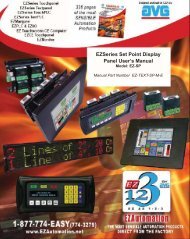
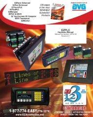
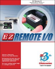
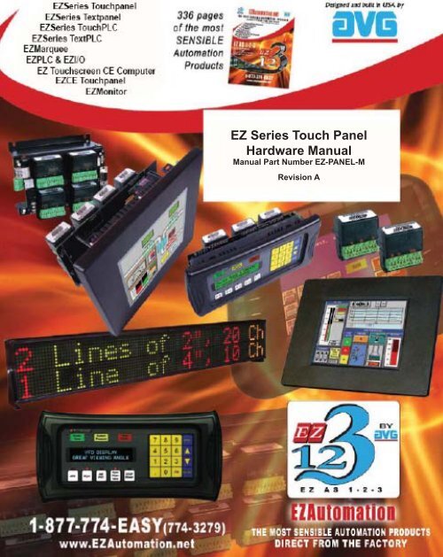
The Most Sensible Automation ProductsDirect From the Factory<strong>EZ</strong> <strong>Series</strong> Touch Panel<strong>Hardware</strong> ManualManual Part Number <strong>EZ</strong>-PANEL-MRevision A
WARNING!Programmable control devices such as <strong>EZ</strong> <strong>Series</strong> Touch Panel are not fail-safe devices and as suchmust not be used for stand-alone protection in any application. Unless proper safeguards are used,unwanted start-ups could result in equipment damage or personal injury. The operator must be madeaware of this hazard and appropriate precautions must be taken.In addition, consideration must be given to the use of an emergency stop function that is independent of the programmable controller.The diagrams and examples in this user <strong>manual</strong> are included for illustrative purposes only. Themanufacturer cannot assume responsibility or liability for actual use based on the diagrams andexamples.CAUTIONDo not press the <strong>EZ</strong> <strong>Series</strong> Touch Panel touchscreen with any sharp objects. This practice maydamage the unit beyond repair.TrademarksThis publication may contain references to products produced and/or offered by other companies.The product and company names may be trademarked and are the sole property of their respectiveowners. <strong>EZ</strong> Automation disclaims any proprietary interest in the marks and names of others.Manual Part Number <strong>EZ</strong>-PANEL-M© Copyright 2005, <strong>EZ</strong>AutomationAll Rights ReservedNo part of this <strong>manual</strong> shall be copied, reproduced, or transmitted in any way without the prior writtenconsent of <strong>EZ</strong>Automation. <strong>EZ</strong>Automation retains the exclusive rights to all information includedin this document.Designed and Built by AVG4140 Utica Ridge Rd. • Bettendorf, IA 52722-1327Marketed by <strong>EZ</strong>Automation4140 Utica Ridge Road • Bettendorf, IA 52722-1327Phone: 1-877-774-EASY • Fax: 1-877-775-EASY • www.<strong>EZ</strong>Automation.net <strong>EZ</strong>-PANEL-M
TABLE OF CONTENTSTable of ContentsWARNING/Caution...............................................................inside front coverTable of Contents ......................................................................................... iManual Revisions ........................................................................................ vEU Information ........................................................................................... vi1 GETTING STARTED ................................................................................1Manual Organization ................................................................................ 1Manual Sections Table ....................................................................... 1Introduction 2What you need to get started ................................................................... 3<strong>Hardware</strong> ........................................................................................... 3Software ............................................................................................. 3Need Help? .............................................................................................. 3Onscreen HELP ................................................................................. 3Fly-Over HELP ................................................................................... 3PLC HELP.......................................................................................... 3Technical Support .............................................................................. 42 MODELS, FEATURES AND ACCESSORIES .........................................56-inch <strong>EZ</strong> <strong>Series</strong> Touch Panel Models ..................................................... 58-inch <strong>EZ</strong> <strong>Series</strong> Touch Panel Models ..................................................... 710-inch, and 15-inch <strong>EZ</strong> <strong>Series</strong> Touch Panel Models .............................. 8Features ................................................................................................. 9PLCs Supported by <strong>EZ</strong> <strong>Series</strong> Touch Panel .......................................... 10Replacement and Optional Equipment .................................................. 11PLC Cable Part Numbers....................................................................... 123 SPECIFICATIONS ................................................................................. 136-inch Models ......................................................................................... 136-inch and 8-inch Standard Bezel Models ............................................. 148-inch, 10-inch, and 15-inch Slim Bezel Models .................................... 154 INSTALLATION .................................................................................... 17Mounting ............................................................................................... 18Method 1. Stud Mounting ................................................................. 186-inch Gray Scale & Color PanelOutline & Cutout Dimensions ................................................. 196-inch White on Blue, Gray Scale, & Color Slim BezelOutline & Cutout Dimensions ................................................. 208-inch Color Slim Bezel Outline Dimensions .............................. 218-inch Color Slim Bezel Cutout Dimensions ............................... 2210-inch Color Slim Bezel Outline Dimensions ............................ 2310-inch Color Slim Bezel Cutout Dimensions ............................. 2415-inch Color Slim Bezel Outline Dimensions ............................ 25iv
TABLE OF CONTENTS15-inch Color Slim Bezel Cutout Dimensions ............................. 26Method 2. DIN Clips ................................................................... 27Connections and Wiring ......................................................................... 29Wiring Diagram ................................................................................ 29Power Terminal ................................................................................ 30PLC Port .......................................................................................... 30COM1 Port ....................................................................................... 31Option Card Installation ................................................................... 32Allen-Bradley Data Highway Plus Option Card .......................... 33<strong>EZ</strong> Ethernet Option Card ........................................................... 34<strong>EZ</strong> Ethernet Option Card Outline Drawing ............................. 35Generic DeviceNet I/O Option Card ........................................... 36Generic Ethernet/IP Option Card ............................................... 37Modicon Modbus Plus Option Card ............................................ 38Generic Profibus-DP Option Card .............................................. 39Mitsubishi CC Link Option Card ................................................. 40Communications Setup .......................................................................... 41Clock ............................................................................................... 41COM1 .............................................................................................. 42Contrast ........................................................................................... 43Touchpad Test .................................................................................. 43Display Test...................................................................................... 44Exit ............................................................................................... 44Reboot ............................................................................................. 445 MAINTENANCE & TROUBLESHOOTING ........................................... 45Shutting Off Power to <strong>EZ</strong> <strong>Series</strong> Touch Panel ....................................... 45Lithium Battery Replacement ................................................................. 47Gasket Replacement.............................................................................. 48Panel Status Indicator Light ................................................................... 48RAM Upgrade ........................................................................................ 49FLASH Program Backup ........................................................................ 50Fuse Reset ............................................................................................. 50Fluorescent Backlight Bulb Replacement .............................................. 51Precautions ............................................................................................ 51Touchscreen/Chemical Compatibility ..................................................... 52Standard Bezel ................................................................................ 52Slim Bezel ........................................................................................ 52Touchscreen Cleaning............................................................................ 54Troubleshooting .....................................................................................55Warranty Repairs ................................................................................... 57APPENDIX A (PLC Cable Wiring Diagrams) ......................................... A-1Allen-Bradley SLC500, 5/01, /02, /03 DH-485/AIC(P/N <strong>EZ</strong>-DH485-CBL) .................................................................... A-1v
Allen-Bradley SLC DF1 RS-232C (P/N <strong>EZ</strong>-SLC-232-CBL).................. A-2Allen-Bradley Micrologix 1000/1200/1500 RS-232C(P/N <strong>EZ</strong>-MLOGIX-CBL) ................................................................. A-2Allen-Bradley PLC5 DF1 RS-232C (P/N <strong>EZ</strong>PLC5-232-CBL) ............... A-2Aromat PLC, RS232 Mini DIN .............................................................. A-3Control Techniques Unidrive 4-wire ..................................................... A-4Control Techniques Unidrive 2-wire ..................................................... A-4Control Technology Corporation (CTC) RS232, RJ-45 Port ................. A-5DirectLogic PLC RJ-12, DL05, DL105, DL205, DL350, and DL450,RS-232C (P/N <strong>EZ</strong>-2CBL) ............................................................... A-6DirectLogic PLC VGA 15-pin, 250, RS-232C (P/N <strong>EZ</strong>-2CBL-1)........... A-6DirectLogic PLC RJ-11, 340, RS-232C (P/N <strong>EZ</strong>-3CBL) ....................... A-6DirectLogic PLC 15-pin D-SUB, DL405, RS-232C(P/N <strong>EZ</strong>-4CBL-1) ........................................................................... A-7DirectLogic PLC 25-pin D-SUB, DL405, 350, 305 DCU, and all DCMsRS-232C (P/N <strong>EZ</strong>-4CBL-2) ............................................................ A-7Idec Micro 3 PLC.................................................................................. A-8Idec MicroSMART PLC ........................................................................ A-9General Electric 90/30 and 90/70 15-pin D-SUB, RS-422A(P/N <strong>EZ</strong>-90-30-CBL) .................................................................... A-10Mitsubishi FX <strong>Series</strong> 25-pin, RS-422A (P/N <strong>EZ</strong>-MITSU-CBL) ........... A-10Mitsubishi FX <strong>Series</strong> 8-pin Mini DIN RS422A .....................................A-11Modicon Modbus RS-232....................................................................A-11Wiring Diagram for the 984 CPU, Quantum 113 CPU ..................A-11Wiring Diagram for AEG Modicon MICRO <strong>Series</strong>: 110CPU 311-xx,110 CPU 411-xx, 110 CPU 512-xx, 110 CPU-612-xx ............. A-12Modicon Modbus with RJ45 ............................................................... A-12Omron C200, C500, RS-232C (P/N <strong>EZ</strong>-OMRON-CBL) ..................... A-13Omron CQM1 and CPM1 ................................................................... A-13Siemens S7 MPI Adaptor, RS-232C (P/N <strong>EZ</strong>-S7MPI-CBL) ............... A-14Siemens S7_200 PLC RS485, D-sub Male 9-pin .............................. A-14Square D Symax, RS422A D-sub Male 9-pin .................................... A-15Texas Instruments 505 <strong>Series</strong> PLC, RS232C .................................... A-15Texas instruments 545-1102 <strong>Series</strong> PLC, RS422A ............................ A-16Texas Instruments 545-1104 <strong>Series</strong> PLC, RS422A ............................ A-16Uni-Telway Telemecanique TSX 37 Micro PLC .................................. A-17<strong>EZ</strong> <strong>Series</strong> Touch Panel RS-422A/RS-485A Wiring Connections forDirectLogic PLCs ............................................................................... A-18<strong>EZ</strong> <strong>Series</strong> Touch Panel RS-422A Wiring Connections forAllen-Bradley SLC 503/504, RS-232C Port ....................................... A-19<strong>EZ</strong>Automation <strong>EZ</strong> <strong>Series</strong> PLC 9-pin D-Sub RS232 ........................... A-20INDEX........ ......................................................................................I-1vi
MANUAL REVISIONSManual RevisionsManual Part Number: <strong>EZ</strong>-PANEL-MManual Title: <strong>EZ</strong> <strong>Series</strong> Touch Panel <strong>Hardware</strong> ManualThe following table provides you with update information. If you call technical support with a questionabout this <strong>manual</strong>, please be aware of the revision number.vii
EU Information<strong>EZ</strong> <strong>Series</strong> Touch Panel is manufactured in compliance with European Union (EU) Directives andcarries the CE mark. <strong>EZ</strong> <strong>Series</strong> Touch Panel has been tested under CE Test Standard #EN55011,and is listed under UL File #E209355. The following information is provided to comply with EU documentationrequirements.Please NOTE: Products with CE marks perform their required functions safelyand adhere to relevant standards as specified by EU directives provided they areused according to their intended purpose and that the instructions in this <strong>manual</strong>are adhered to. The protection provided by the equipment may be impaired ifthis equipment is not used in accordance with this <strong>manual</strong>. Only replacementparts supplied by <strong>EZ</strong>Automation or its agents should be used.TechnicalSupportConsult <strong>EZ</strong> <strong>Series</strong> Touch Panel Editor Programming Software Help or you mayfind answers to your questions in the operator interface section of our web site@ www.<strong>EZ</strong>Automation.net. If you still need assistance, please call our technicalsupport at 1-877-774-EASY or FAX us at 1-877-775-EASY.SELV CircuitsAll electrical circuits connected to the communications port receptacle are ratedas Safety Extra Low Voltage (SELV).EnvironmentalSpecificationsOperating Temperature6” White on Blue & Mono non-expandable ................................0 to 45 °C6” Color ...................................................................................0 to 50 °C6” Color TFT ...............................................................................0 to 55 °C8” Color ...................................................................................0 to 50 °C8” Color TFT ...............................................................................0 to 55 °C10” Color ...................................................................................0 to 55 °C15” Color ...................................................................................0 to 55 °CStorage Temperature6” White on Blue & Mono non-expandable ...........................-20 to +60 °C6” Color ..............................................................................-25 to +60 °C6” Color TFT ..........................................................................-25 to +65 °C8” Color ..............................................................................-25 to +60 °C8” Color TFT ..........................................................................-25 to +65 °C10” Color ..............................................................................-25 to +65 °C15” Color ..............................................................................-25 to +65 °COperating Humidity ....................................... 10–95% R.H., noncondensingAir Composition ............................................. No corrosive gases permittedPreventativeMaintenanceand CleaningNo preventative maintenance is required. The <strong>EZ</strong> <strong>Series</strong> Touch Panel touchscreenshould be cleaned as needed with warm, soapy water. See Chapter 5, Maintenance,for a list of compatible/incompatible chemicals and compounds.viii
This page intentionally left blankix
Touch Panel <strong>Hardware</strong> ManualChapter 1 - Getting StartedChaptersThe table, below provides an overall description of the topics covered within this <strong>manual</strong>.1Getting StartedProvides Manual Organization, and lists what you needto get started, hardware and software. Discusses how toget help with questions or problems you might encounterthrough Onscreen Help and Technical Support.23Models, Features,and AccessoriesSpecificationsProvides you with a table listing the various models, theirpart numbers and special features. Lists the importantfeatures of all <strong>EZ</strong> <strong>Series</strong> Touch Panel models. Lists thePLCs supported by the panels, by brand, model andprotocol. Lists the replacement and optional equipmentavailable, including memory cards, PLC cables andprogramming cable.Specifications for each model provide detailed information.Included are display size, brightness and pixels;CPU type; service power requirements; operating andstorage temperatures; available memory; serial communicationsspecs; dimensions, weight, etc.4InstallationShows the mounting and cutout dimensions for the panelmodels. Tells you how to connect the unit to power supply,programming computer, printer, and a PLC. Specialoption card connector instructions are also provided.Shows the setup screens displayed after initial powerupof the panel. Describes each setup screen and how touse it to set up your panel.5Maintenance &TroubleshootingProvides instructions on battery replacement, gasketreplacement, memory upgrade (FLASH and RAM), FuseReset, and fluorescent backlight replacement. Discussesprecautions and cleaning necessary to ensure longevityof the panel. Aids in diagnosing problems you mightencounter when installing or operating your <strong>EZ</strong> <strong>Series</strong>Touch Panel. Provides steps to take to isolate and correctproblems.AAppendix APLC Cable Wiring Diagrams are provided.1 Chapter 1 - Getting Started <strong>EZ</strong>-PANEL-M
Touch Panel <strong>Hardware</strong> Manual1 GETTING STARTEDIntroduction<strong>EZ</strong> <strong>Series</strong>Easy as 1 - 2 - 3There are two <strong>manual</strong>s that you will need to use the <strong>EZ</strong> <strong>Series</strong> Touch Panel —this <strong>manual</strong>, the <strong>EZ</strong> <strong>Series</strong> Touch Panel <strong>Hardware</strong> User Manual, and the <strong>EZ</strong><strong>Series</strong> Touch Panel Editor User Manual (included with P/N <strong>EZ</strong>P-PANELEDIT, <strong>EZ</strong><strong>Series</strong> Touch Panel Editor Programming Software). Don’t worry — you won’t bebouncing back and forth between them — and we’ll always let you know exactlywhere the information is that you will need for the next step.These <strong>manual</strong>s will take you through the steps necessary to get your <strong>EZ</strong> <strong>Series</strong>Touch Panel up and running in the shortest possible time. Although your familiaritywith programmable graphic operator interface devices will determine how quicklyyou move through the steps — it’s as easy as 1 — 2 — 3. The flow chart belowwill show you where you need to go, and — how to get there from here!123InstallSoftwareInstall<strong>Hardware</strong>DesignScreens<strong>EZ</strong> <strong>Series</strong> Touch Panel Editor Programming Software is a user-friendly Windowsbasedprogram that allows you to design screens for the <strong>EZ</strong> <strong>Series</strong> Touch Paneloperator interfaces. To install <strong>EZ</strong> <strong>Series</strong> Touch Panel Editor Programming Software,run the install program from the CD and follow the onscreen prompts. Formore information, please refer to the <strong>EZ</strong> <strong>Series</strong> Touch Panel Editor ProgrammingSoftware Manual.You can start designing your screen off-line immediately after installing<strong>EZ</strong> <strong>Series</strong> Touch Panel Editor Programming Software — you don’t needto have the hardware installed!This <strong>manual</strong> will provide you with the instructions you need to install the<strong>EZ</strong> <strong>Series</strong> Touch Panel. Included are mounting diagrams for both Stud Mounting(page 18) and DIN Clip Mounting (page 27). Connections and wiring requirementsare provided beginning on page 29. Option Card connector informationis provided beginning on page 32. Communications Setup instructions beginon page 41. For Maintenance information, see Chapter 5 (page 45) and forTroubleshooting, refer to page 55.You may design your screen on-line or off-line (without connection to an <strong>EZ</strong><strong>Series</strong> Touch Panel). When designing screens with <strong>EZ</strong> <strong>Series</strong> Touch PanelProgramming Software, you will program objects on the <strong>EZ</strong> <strong>Series</strong> Touch Panelproviding a graphical interface designed to interchange and display data from aPLC by merely viewing or touching the screen — all unique to your particularapplication. For instructions on how to design screens, refer to the <strong>EZ</strong> <strong>Series</strong>Touch Panel Editor User Manual.<strong>EZ</strong>-PANEL-MChapter 1 - Getting Started2
Touch Panel <strong>Hardware</strong> ManualWhat you need to get started:Need HELP?<strong>Hardware</strong>• <strong>EZ</strong> <strong>Series</strong> Touch Panel• 24 Volt Power Supply (24 VDC with 1.5A supply is recommended)(1.5 Amp Slo-Blo input power fuse is also recommended)• Programming Cable (P/N <strong>EZ</strong>-PGMCBL)• PLC Interface Cable (see page 12 for part numbers)• PC requirements:— IBM or compatible PC (Pentium II, AMD Athlon or better) with amouseand separate serial port— VGA display with at least 800 x 600 resolution (1024 x 768recommended)— Standard Windows 98/NT4.0/2000 ® /XP Home/XP ProRequirements— CD ROM DriveSoftware• <strong>EZ</strong> <strong>Series</strong> Touch Panel Editor (P/N <strong>EZ</strong>-PANELEDIT)Help is never more than a mouse click or a key press away!Onscreen HELPOne of the most important features of the <strong>EZ</strong> <strong>Series</strong> Touch Panel Editor is theavailability of context sensitive onscreen help. To access the Help windows, simplypress the F1 function key while on the topic where you need help. For example,if you need help while working with screens, hit the F1 function key while in thatarea and a popup window will be displayed. Also, most dialog boxes contain aHelp button, you may click on it to get help, too!Fly-Over HELPWhen the mouse cursor comes to rest over any tool bar or object button for ashort while, a small window will appear containing a brief description of the functionof that particular button. The window will disappear as soon as the cursorhas been moved off the button.PLC HELPIf you need help with the PLC to <strong>EZ</strong> <strong>Series</strong> Touch Panel Interface, consult the <strong>EZ</strong><strong>Series</strong> Touch Panel Enhanced Editor Programming Software Help. Each PLCDriver has a Help Topic that lists the error messages and provides an explanationfor each. Also provided are PLC to <strong>EZ</strong> <strong>Series</strong> Touch Panel wiring diagrams.3 Chapter 1 - Getting Started <strong>EZ</strong>-PANEL-M
Touch Panel <strong>Hardware</strong> Manual1 GETTING STARTEDTechnical SupportAlthough most questions can be answered with <strong>EZ</strong> <strong>Series</strong> Touch Panel HELP orthe <strong>manual</strong>s, if you are still having difficulty with a particular aspect of installationor screen design, technical support is available at 1-877-774-EASY or FAX usat 1-877-775-EASY. Visit our website at www.<strong>EZ</strong>Automation.net.PLEASE NOTE: The Troubleshooting section of this<strong>manual</strong> (see page 55) should be able to help you with most problems you mightencounter.<strong>EZ</strong>-PANEL-MChapter 1 - Getting Started4
Touch Panel <strong>Hardware</strong> ManualChapter 2 - Models, Features, & Accessories Models6-inch Monochrome <strong>EZ</strong> <strong>Series</strong> Touch Panel ModelsPart Number<strong>EZ</strong>-S6M-R*<strong>EZ</strong>-S6W-RS*<strong>EZ</strong>-S6W-RSU<strong>EZ</strong>-S6M-RS<strong>EZ</strong>-S6M-F<strong>EZ</strong>-S6M-FH<strong>EZ</strong>-S6M-FS<strong>EZ</strong>-S6M-FSH*<strong>EZ</strong>-S6M-FSD*<strong>EZ</strong>-S6M-FSE*<strong>EZ</strong>-S6M-FSM*<strong>EZ</strong>-S6M-FSP*<strong>EZ</strong>-S6M-FST*<strong>EZ</strong>-S6M-FSC*<strong>EZ</strong>-S6M-FSU*<strong>EZ</strong>-S6M-ESDescription6” Mono withStandard Bezel6” Mono Whiteon Blue with SlimBezel6” Mono Whiteon Blue with SlimBezel6” Mono with SlimBezel6” Mono withStandard Bezel6” Mono withStandard Bezel6” Mono with SlimBezel6” Mono with SlimBezel6” Mono with SlimBezel6” Mono with SlimBezel6” Mono with SlimBezel6” Mono with SlimBezel6” Mono Grayscalewith Slim Bezel6” Mono Grayscalewith Slim Bezel6” Mono Grayscalewith Slim Bezel6” Mono Grayscalewith Slim BezelUserMemoryFieldExpandableUser RAM?NonvolatileFlashBackupCard Optionfor ProgramBackup?PLC DriversUpported?256KB No No See Note below256KB No No All Serial Drivers256KB No NoONLY UniversalEthernet256KB No No See Note below512KB512KB512KB512KB512KB512KB512KB512KB512KB512KB512KB512KBYes, to 1 or2 MBYes, to 1 or2 MBYes, to 1 or2 MBYes, to 1 or2 MBYes, to 1 or2 MBYes, to 1 or2 MBYes, to 1 or2 MBYes, to 1 or2 MBYes, to 1 or2 MBYes, to 1 or2 MBYes, to 1 or2 MBYes, to 1 or2 MBNEMANEMA 4,4XNEMA 1,FDANEMA 1,FDANEMA 1,FDA<strong>EZ</strong>Automation <strong>EZ</strong> <strong>Series</strong> Touch Panel NEMA RatingsThe NEMA rating of all operator interface products in this <strong>manual</strong> relates to only the front bezel since only the front bezel is exposed to the externalenvironment and the backend is enclosed inside an appropriately sealed enclosure used by the customer. The <strong>Touchpanel</strong>s in this <strong>manual</strong> have eitherNEMA 1 FDA Compliant or NEMA 4, 4X (indoor) rating. Please note that the touchpanels that are rated NEMA 1 FDA Compliant can handle typicalNEMA 4, 4X environments such as water seepage or hosedown. The only reason these panels do not have NEMA 4, 4X rating is because the FDACompliant plastic material is not UL approved for NEMA 4 flammability.5 Chapter 2 - Models, Features, & Accessories <strong>EZ</strong>-PANEL-MYesYesYesYesYesYesYesYesYesYesYesYesAll, plus <strong>EZ</strong>EthernetAll, plus AB DH+and Remove I/OAll, plus <strong>EZ</strong>EthernetAll, plus AB DH+and Remove I/OAll, plus DeviceNetAll, plus EthernetI/PAll, plus MB+All, plus Profi busAll, plus ModBusTCP/IPAll, plus CC LinkONLY UniversalEthernetONLY <strong>EZ</strong> <strong>Series</strong>PLCNEMA 4,4XNEMA 4,4XNEMA 1,FDANEMA 1,FDANEMA 1,FDANEMA 1,FDANEMA 1,FDANEMA 1,FDANEMA 1,FDANEMA 1,FDANEMA 1,FDANEMA 1,FDA
Touch Panel <strong>Hardware</strong> Manual6-inch Color <strong>EZ</strong> <strong>Series</strong> Touch Panel ModelsIn the table below are the 6-inch Color <strong>EZ</strong> <strong>Series</strong> Touch Panel models. If using an option boardconnector, you cannot use the PLC port at the same time to connect to another type PLC. Thepanel supports only one PLC driver at a time.Part NumberDescriptionUserMemoryFieldExpandableUser RAM?NonvolatileFlash BackupCard Optionfor ProgramBackup?PLC Drivers Upported?NEMA<strong>EZ</strong>-S6C-K6” STN Color withStandard Bezel512KBYes, to 1 or2 MBYesONLY Direct Logic PLCNEMA 4,4X<strong>EZ</strong>-S6C-KS6” STN Color withSlim Bezel512KBYes, to 1 or2 MBYesONLY Direct Logic PLCNEMA 1,FDA<strong>EZ</strong>-S6C-F6” STN Color withStandard Bezel512KBYes, to 1 or2 MBYesAll, plus <strong>EZ</strong> EthernetNEMA 4,4X<strong>EZ</strong>-S6C-FH6” STN Color withStandard Bezel512KBYes, to 1 or2 MBYesAll, plus AB DH+ and Remote I/ONEMA 4,4X<strong>EZ</strong>-S6C-FS6” STN Color withSlim Bezel512KBYes, to 1 or2 MBYesAll, plus <strong>EZ</strong> EthernetNEMA 1,FDA<strong>EZ</strong>-T6C-FS6” TFT Color with SlimBezel512KBYes, to 1 or2 MBYesAll, plus <strong>EZ</strong> EthernetNEMA 1,FDA*<strong>EZ</strong>-S6C-FSD6” STN Color withSlim Bezel512KBYes, to 1 or2 MBYesAll, plus DeviceNetNEMA 1,FDA*<strong>EZ</strong>-T6C-FSD6” TFT Color with SlimBezel512KBYes, to 1 or2 MBYesAll, plus DeviceNetNEMA 1,FDA*<strong>EZ</strong>-S6C-FSE6” STN Color withSlim Bezel512KBYes, to 1 or2 MBYesAll, plus Ethernet I/PNEMA 1,FDA*<strong>EZ</strong>-T6C-FSE6” TFT Color with SlimBezel512KBYes, to 1 or2 MBYesAll, plus Ethernet I/PNEMA 1,FDA<strong>EZ</strong>-S6C-FSH6” STN Color withSlim Bezel512KBYes, to 1 or2 MBYesAll, plus AB DH+ and Remote I/ONEMA 1,FDA<strong>EZ</strong>-T6C-FSH6” TFT Color with SlimBezel512KBYes, to 1 or2 MBYesAll, plus AB DH+ and Remote I/ONEMA 1,FDA<strong>EZ</strong>-S6C-FSM6” STN Color withSlim Bezel512KBYes, to 1 or2 MBYesAll, plus MB+NEMA 1,FDA<strong>EZ</strong>-T6C-FSM6” TFT Color with SlimBezel512KBYes, to 1 or2 MBYesAll, plus MB+NEMA 1,FDA<strong>EZ</strong>-S6C-FSP6” STN Color withSlim Bezel512KBYes, to 1 or2 MBYesAll, plus ProfibusNEMA 1,FDA<strong>EZ</strong>-T6C-FSP6” TFT Color with SlimBezel512KBYes, to 1 or2 MBYesAll, plus ProfibusNEMA 1,FDA*<strong>EZ</strong>-S6C-FST*<strong>EZ</strong>-T6C-FST*<strong>EZ</strong>-T6C-FSC*<strong>EZ</strong>-S6C-FSU*<strong>EZ</strong>-T6C-FSU*<strong>EZ</strong>-S6C-ES<strong>EZ</strong>-T6C-ES6” STN Color withSlim Bezel6” TFT Color with SlimBezel6” STN Color withSlim Bezel6” STN Color withSlim Bezel6” TFT Color with SlimBezel6” STN Color withSlim Bezel6” TFT Color with SlimBezel512KB512KB512KB512KB512KB512KB512KBYes, to 1 or2 MBYes, to 1 or2 MBYes, to 1 or2 MBYes, to 1 or2 MBYes, to 1 or2 MBYes, to 1 or2 MBYes, to 1 or2 MB*Indicates NEW <strong>EZ</strong> <strong>Series</strong> Touch Panel Models.NOTE: Suppots Automation Direct (Direct Logic) serial drivers including H2-WPLC-XX.YesYesYesYesYesYesYesAll, plus ModBus TCP/IPAll, plus ModBus TCP/IPAll, plus CC LinkONLY Universal EthernetONLY Universal EthernetONLY <strong>EZ</strong> <strong>Series</strong> PLCONLY <strong>EZ</strong> <strong>Series</strong> PLCNEMA 1,FDANEMA 1,FDANEMA 1,FDANEMA 1,FDANEMA 1,FDANEMA 1,FDANEMA 1,FDA<strong>EZ</strong>-PANEL-MChapter 2 - Models, Features, & Accessories6
Touch Panel <strong>Hardware</strong> Manual8-inch Color <strong>EZ</strong> <strong>Series</strong> Touch Panel ModelsIn the table below are the 8-inch <strong>EZ</strong> <strong>Series</strong> Touch Panel models. If using an option board connector,you cannot use the PLC port at the same time to connect to another type PLC. The panelsupports only one PLC driver at a time.Part NumberDescriptionUserMemoryFieldExpandable UserRAM?NonvolatileFlash BackupCard Optionfor ProgramBackup?PLC Drivers Upported?NEMA<strong>EZ</strong>-S8C-F 8” STN Color with Slim Bezel 512KB Yes, to 1 or 2 MB Yes All, plus <strong>EZ</strong> Ethernet NEMA 4, 4X<strong>EZ</strong>-T8C-F 8” TFT Color with Slim Bezel 512KB Yes, to 1 or 2 MB Yes All, plus <strong>EZ</strong> Ethernet NEMA 4, 4X<strong>EZ</strong>-S8C-FH 8” STN Color with Slim Bezel 512KB Yes, to 1 or 2 MB Yes<strong>EZ</strong>-T8C-FH 8” TFT Color with Slim Bezel 512KB Yes, to 1 or 2 MB YesAll, plus AB DH+ andRemote I/OAll, plus AB DH+ andRemote I/ONEMA 4, 4XNEMA 4, 4X<strong>EZ</strong>-S8C-FS 8” STN Color with Slim Bezel 512KB Yes, to 1 or 2 MB Yes All, plus <strong>EZ</strong> Ethernet NEMA 1, FDA*<strong>EZ</strong>-S8C-FSD 8” STN Color with Slim Bezel 512KB Yes, to 1 or 2 MB Yes All, plus DeviceNet NEMA 1, FDA*<strong>EZ</strong>-S8C-FD 8” STN Color with Slim Bezel 512KB Yes, to 1 or 2 MB Yes All, plus DeviceNet NEMA 4, 4X*<strong>EZ</strong>-T8C-FD 8” TFT Color with Slim Bezel 512KB Yes, to 1 or 2 MB Yes All, plus DeviceNet NEMA 4, 4X*<strong>EZ</strong>-S8C-FSE 8” STN Color with Slim Bezel 512KB Yes, to 1 or 2 MB Yes All, plus Ethernet I/P NEMA 1, FDA*<strong>EZ</strong>-S8C-FE 8” STN Color with Slim Bezel 512KB Yes, to 1 or 2 MB Yes All, plus Ethernet I/P NEMA 4, 4X*<strong>EZ</strong>-T8C-FE 8” TFT Color with Slim Bezel 512KB Yes, to 1 or 2 MB Yes All, plus Ethernet I/P NEMA 4, 4X<strong>EZ</strong>-S8C-FSH 8” STN Color with Slim Bezel 512KB Yes, to 1 or 2 MB YesAll, plus AB DH+ andRemote I/ONEMA 1, FDA*<strong>EZ</strong>-S8C-FSM 8” STN Color with Slim Bezel 512KB Yes, to 1 or 2 MB Yes All, plus MB+ NEMA 1, FDA*<strong>EZ</strong>-S8C-FM 8” STN Color with Slim Bezel 512KB Yes, to 1 or 2 MB Yes All, plus MB+ NEMA 4, 4X*<strong>EZ</strong>-T8C-FM 8” TFT Color with Slim Bezel 512KB Yes, to 1 or 2 MB Yes All, plus MB+ NEMA 4, 4X*<strong>EZ</strong>-S8C-FSP 8” STN Color with Slim Bezel 512KB Yes, to 1 or 2 MB Yes All, plus Profibus NEMA 1, FDA*<strong>EZ</strong>-S8C-FP 8” STN Color with Slim Bezel 512KB Yes, to 1 or 2 MB Yes All, plus Profibus NEMA 4, 4X*<strong>EZ</strong>-T8C-FP 8” TFT Color with Slim Bezel 512KB Yes, to 1 or 2 MB Yes All, plus Profibus NEMA 4, 4X*<strong>EZ</strong>-S8C-FST 8” Color with Slim Bezel 512KB Yes, to 1 or 2 MB Yes All, plus ModBus TCP/IP NEMA 1, FDA*<strong>EZ</strong>-S8C-FT 8” STN Color with Slim Bezel 512KB Yes, to 1 or 2 MB Yes All, plus ModBus TCP/IP NEMA 4, 4X*<strong>EZ</strong>-T8C-FT 8” TFT Color with Slim Bezel 512KB Yes, to 1 or 2 MB Yes All, plus ModBus TCP/IP NEMA 4, 4X*<strong>EZ</strong>-S8C-FSC 8” STN Color with Slim Bezel 512KB Yes, to 1 or 2 MB Yes All, plus CC Link NEMA 1, FDA*<strong>EZ</strong>-S8C-FC 8” STN Color with Slim Bezel 512KB Yes, to 1 or 2 MB Yes All, plus CC Link NEMA 4, 4X*<strong>EZ</strong>-T8C-FC 8” TFT Color with Slim Bezel 512KB Yes, to 1 or 2 MB Yes All, plus CC Link NEMA 4, 4X*<strong>EZ</strong>-S8C-FSU 8” Color with Slim Bezel 512KB Yes, to 1 or 2 MB Yes ONLY Universal Ethernet NEMA 1, FDA*<strong>EZ</strong>-S8C-FU 8” STN Color with Slim Bezel 512KB Yes, to 1 or 2 MB Yes ONLY Universal Ethernet NEMA 4, 4X*<strong>EZ</strong>-T8C-FU 8” TFT Color with Slim Bezel 512KB Yes, to 1 or 2 MB Yes ONLY Universal Ethernet NEMA 4, 4X*<strong>EZ</strong>-T8C-E 8” TFT Color with Slim Bezel 512KB Yes, to 1 or 2 MB Yes ONLY <strong>EZ</strong> <strong>Series</strong> PLC NEMA 4, 4X*Indicates NEW <strong>EZ</strong> <strong>Series</strong> Touch Panel Models.7 Chapter 2 - Models, Features, & Accessories <strong>EZ</strong>-PANEL-M
Touch Panel <strong>Hardware</strong> Manual10-inch and 15-inch <strong>EZ</strong> <strong>Series</strong> Touch Panel ModelsIn the table below are the 10-inch and 15-inch <strong>EZ</strong> <strong>Series</strong> Touch Panel models. If using an optionboard connector, you cannot use the PLC port at the same time to connect to another type PLC.The panel supports only one PLC driver at a time.Part NumberDescriptionUserMemoryFieldExpandable UserRAM?NonvolatileFlash BackupCard Optionfor ProgramBackup?PLC Drivers Upported?NEMA<strong>EZ</strong>-T10C-F 10.4” TFT Color with Slim Bezel 512KB Yes, to 1 or 2 MB Yes All Serial Drivers NEMA 4, 4X<strong>EZ</strong>-T10C-FH 10.4” TFT Color with Slim Bezel 512KB Yes, to 1 or 2 MB YesAll, plus AB DH+ andRemote I/ONEMA 4, 4X<strong>EZ</strong>-T10C-FS 10.4” TFT Color with Slim Bezel 512KB Yes, to 1 or 2 MB Yes All, plus <strong>EZ</strong> Ethernet NEMA 1, FDA<strong>EZ</strong>-T10C-FD 10.4” TFT Color with Slim Bezel 512KB Yes, to 1 or 2 MB Yes All, plus DeviceNet I/O NEMA 4, 4X<strong>EZ</strong>-T10C-FSD 10.4” TFT Color with Slim Bezel 512KB Yes, to 1 or 2 MB Yes All, plus DeviceNet I/O NEMA 1, FDA<strong>EZ</strong>-T10C-FE 10.4” TFT Color with Slim Bezel 512KB Yes, to 1 or 2 MB Yes All, plus Ethernet I/P NEMA 4, 4X<strong>EZ</strong>-T10C-FSE 10.4” TFT Color with Slim Bezel 512KB Yes, to 1 or 2 MB Yes All, plus Ethernet I/P NEMA 1, FDA<strong>EZ</strong>-T10C-FSH 10.4” TFT Color with Slim Bezel 512KB Yes, to 1 or 2 MB YesAll, plus AB DH+ andRemote I/ONEMA 1, FDA<strong>EZ</strong>-T10C-FM 10.4” TFT Color with Slim Bezel 512KB Yes, to 1 or 2 MB Yes All, plus Modbus Plus NEMA 4, 4X<strong>EZ</strong>-T10C-FSM 10.4” TFT Color with Slim Bezel 512KB Yes, to 1 or 2 MB Yes All, plus Modbus Plus NEMA 1, FDA<strong>EZ</strong>-T10C-FP 10.4” TFT Color with Slim Bezel 512KB Yes, to 1 or 2 MB Yes All, plus Profibus NEMA 4, 4X<strong>EZ</strong>-T10C-FSP 10.4” TFT Color with Slim Bezel 512KB Yes, to 1 or 2 MB Yes All, plus Profibus NEMA 1, FDA<strong>EZ</strong>-T10C-FT 10.4” TFT Color with Slim Bezel 512KB Yes, to 1 or 2 MB Yes All, plus ModBus TCP/IP NEMA 4, 4X<strong>EZ</strong>-T10C-FST 10.4” TFT Color with Slim Bezel 512KB Yes, to 1 or 2 MB Yes All, plus ModBus TCP/IP NEMA 1, FDA<strong>EZ</strong>-T10C-FC 10.4” TFT Color with Slim Bezel 512KB Yes, to 1 or 2 MB Yes All, plus CC Link NEMA 4, 4X<strong>EZ</strong>-T10C-FSC 10.4” TFT Color with Slim Bezel 512KB Yes, to 1 or 2 MB Yes All, plus CC Link NEMA 1, FDA<strong>EZ</strong>-T10C-FU 10.4” TFT Color with Slim Bezel 512KB Yes, to 1 or 2 MB Yes ONLY Universal Ethernet NEMA 4, 4X<strong>EZ</strong>-T10C-FSU 10.4” TFT Color with Slim Bezel 512KB Yes, to 1 or 2 MB Yes ONLY Universal Ethernet NEMA 1, FDA<strong>EZ</strong>-T10C-E 10.4” TFT Color with Slim Bezel 512KB Yes, to 1 or 2 MB Yes ONLY <strong>EZ</strong> <strong>Series</strong> PLC NEMA 4, 4X<strong>EZ</strong>-T15C-FS 15” TFT Color with Slim Bezel 1MB Yes, to 1 or 2 MB Yes All, plus <strong>EZ</strong> Ethernet NEMA 1, FDA<strong>EZ</strong>-T15C-FSD 15” TFT Color with Slim Bezel 1MB Yes, to 1 or 2 MB Yes All, plus DeviceNet I/O NEMA 1, FDA<strong>EZ</strong>-T15C-FSE 15” TFT Color with Slim Bezel 1MB Yes, to 1 or 2 MB Yes All, plus Ethernet IP NEMA 1, FDA<strong>EZ</strong>-T15C-FSH 15” TFT Color with Slim Bezel 1MB Yes, to 1 or 2 MB YesAll, plus AB DH+ andRemote I/ONEMA 1, FDA<strong>EZ</strong>-T15C-FSM 15” TFT Color with Slim Bezel 1MB Yes, to 1 or 2 MB Yes All, plus Modbus Plus NEMA 1, FDA<strong>EZ</strong>-T15C-FSP 15” TFT Color with Slim Bezel 1MB Yes, to 1 or 2 MB Yes All, plus Profibus NEMA 1, FDA<strong>EZ</strong>-T15C-FST 15” TFT Color with Slim Bezel 1MB Yes, to 1 or 2 MB Yes All, plus Modbus TCP/IP NEMA 1, FDA<strong>EZ</strong>-T15C-FSC 15” TFT Color with Slim Bezel 1MB Yes, to 1 or 2 MB Yes All, plus CC Link NEMA 1, FDA<strong>EZ</strong>-T15C-FSU 15” TFT Color with Slim Bezel 1MB Yes, to 1 or 2 MB Yes ONLY Universal Ethernet NEMA 1, FDA<strong>EZ</strong>-PANEL-MChapter 2 - Models, Features, & Accessories8
Touch Panel <strong>Hardware</strong> ManualFeatures• Pre-built panel components for easy screen design• Screen Objects such as: Toggle Switch, Slide Switch,Selector Switch, Throw Switch, Thumbwheel Object, Meters,PID Face plates, and Analog/Digital Clock• Flash memory-based design for easy fi rmware upgrade• Field expandable user RAM (not all models)• Nonvolatile fl ash card option for user program backup(not all models)• Color models support 128-color palette for components andbitmaps• 16 shades of gray on monochrome models• Multiple languages (up to 9)PLC• Two communications ports — Computer (RS-232C) and(RS-232C, RS-422A, or RS-485A)• Up to 999 screens• Built-in clock and calendar or reference the PLC clock• Built-in soft keypad for numeric and alphanumeric entry• Password Protection for every touch object• Passwords for up to 8 user groups• 16 level undo and redo• Import bitmaps• Serial Printer support• 40-character tag names allow you to use meaningful namesfor PLC memory locations instead of cryptic PLC addresses• New features including: overlapping of objects, free-sizingof touch objects, Pick and Apply Attributes, display address9 Chapter 2 - Models, Features, & Accessories <strong>EZ</strong>-PANEL-M
Touch Panel <strong>Hardware</strong> ManualPL Cs Supported by the <strong>EZ</strong> <strong>Series</strong> Touch PanelsPLC BrandModelProtocolsSupported<strong>EZ</strong>Automation <strong>EZ</strong> <strong>Series</strong> PLC <strong>EZ</strong> ProtocolMicroLogix 1000/1200/1500, SLC500,5/01, /02, /03DH 485/AIC/AIC+MicroLogix 1000/1200/1500SLC 5/03, 5/04, and 5/05DF1 Half Duplex/DF1 Full DuplexAllen BradleySLC 504, PLC5DH+ (Option Card)PLC 5DF1PLC 2, 3, and 5Remote I/O (with DH+ Plus Option Card)Aromat Aromat Mewtocol COMControl Techniques Unidrive 2-wire, 4-wire BinaryControl TechnologyCorporation (CTC)CTC 2600, 2700, and 5100CTC BinaryDeviceNet DeviceNet I/O DeviceNet I/O (OptionCard)Ethernet Control Logic, Micro Logic, Compact Logic, GE Versamax Ethernet I/P, SRTP, DF1, Modbus TCP/IPGeneral Electric 90/30 and 90/70 Versamax SNPX/SNPIdec Idec Computer LinkMitsubishiFX <strong>Series</strong> (all)FX, DirectCC LinkCC Link Protocol984 CPU, Quantum 113 CPU, AEG Modicon Micro <strong>Series</strong>Modicon110, CPU: 311-xx, 411-xx, 512-xx, 612-xxModbus RTU984 <strong>Series</strong>, Qunatum <strong>Series</strong> Modicon Plus (Option Card)Omron C200, C500, CQM1, CPM1, CPM2 Host LinkProfi bus Profibus-DP Generic Profibus DP(Option Card)DL105K-Sequence, DirectNet,Modbus (Koyo Addressing)DL105K-SequenceDL205D2-230 K-SequenceD2-240 K-Sequence; DirectNetD2-250/D2-250 - 1/260K-Sequence; DirectNet;ModBus (Koyo addressing)D2-240/250 w/DCMDirectNetDirect LogicDL305DL405D3-330/330PDirectNetD3-340 DirectNetD3-350K-Sequence; DirectNet;ModBus (Koyo addressing)D3-350 w/DCM DirectNetD4-430 K-Sequence; DirectNetD4-440 K-Sequence; DirectNetD4-450K-Sequence; DirectNet;ModBus (Koyo addressing)SiemensSiemens S7 MPI AdaptorSiemens S7_200All with DCMDirectNet3964RSiemens S7_200Square D Symax 300 <strong>Series</strong> CPU, 400 <strong>Series</strong> CPU SymaxTexas InstrumentsTI5X5 <strong>Series</strong>, TI505, TI545-1102, TI545-1104TBP (Transparent ByteProtocol) or NITP(Non-Intelligent Terminal Protocol)Uni-Telway Telemecanique TSX 37 Micro UNI-TE (Version 1.1)OtherH2- WinPLC (Entivity (Think & Do) V5.2 orlater, check forversion compatabilityEntivity (Think & Do) Modbus RTU (Serial Port)<strong>EZ</strong>-PANEL-MChapter 2 - Models, Features, & Accessories10
Touch Panel <strong>Hardware</strong> ManualReplacement and Optional EquipmentThere are replacement parts and other optional equipment available tocustomize or upgrade <strong>EZ</strong> <strong>Series</strong> Touch Panel to fit your application. The tablebelow is a list of available equipment. Instructions, if necessary, on how toinstall thisequipment to upgrade your unit are also provided. (For instructions to mount thePart NumberDescription<strong>EZ</strong>-PANELEDIT <strong>EZ</strong> <strong>Series</strong> Touch Panel Programming Software<strong>EZ</strong>-PANEL-M <strong>Hardware</strong> User Manual<strong>EZ</strong>-RAM-1512K RAM Card<strong>EZ</strong>-RAM-21MB RAM Card<strong>EZ</strong>-FLASH-1512K Flash Card<strong>EZ</strong>-FLASH-21MB Flash Card<strong>EZ</strong>-FLASH-32MB Flash Card<strong>EZ</strong>-ETHERNET DirectLogic Ethernet Option Interface Card<strong>EZ</strong>-ETHERPLUS Modbus TC P/IP or DirectLogic Ethernet Option Card<strong>EZ</strong>-BATReplacement 1/2 AA, 3.6 volt Lithium Battery<strong>EZ</strong>-BRK-1 <strong>EZ</strong> <strong>Series</strong> Touch Panel optional D IN Mounting Clips (pk. of 2)<strong>EZ</strong>-COMON315-pin male D-sub connectors with terminal blocks, for connecting RS422 networkcable from <strong>EZ</strong> <strong>Series</strong> Touch Panels or <strong>EZ</strong> <strong>Series</strong> Text panels<strong>EZ</strong>-PANEL6-GSK (6”) Standard Replacement Gasket<strong>EZ</strong>-PANEL8-GSK (8”) Standard Replacement Gasket<strong>EZ</strong>-PANEL10-GSK (10”) Standard Replacement Gasket<strong>EZ</strong>-PANEL-STUDS Spare mounting studs (four with nuts)<strong>EZ</strong>-6SLIMF-GSK (6”) Slim bezel FDA replacement gasket<strong>EZ</strong>-8SLIMF-GSK (8”) Slim bezel FDA replacement gasket<strong>EZ</strong>-10SLIMF-GSK (10”) Slim bezel FD A replacement gasket<strong>EZ</strong>-15SLIMF-GSK (15”) Slim bezel FD A replacement gasket<strong>EZ</strong>-COV6Pack of 3 protective shields for any 6” <strong>EZ</strong> <strong>Series</strong> Touch panel<strong>EZ</strong>-COV8Pack of 3 protective shields for any 8” <strong>EZ</strong> <strong>Series</strong> Touch panel<strong>EZ</strong>-COV10Pack of 3 protective shields for any 10” <strong>EZ</strong> <strong>Series</strong> Touch panel<strong>EZ</strong>-COV15Pack of 3 protective shields for any 15”<strong>EZ</strong>T <strong>Series</strong> Touch panelTo order from this list, phone <strong>EZ</strong>Automation at 1-877-774-EASY.11 Chapter 2 - Models, Features, & Accessories <strong>EZ</strong>-PANEL-M
PLC Cable Part NumbersTouch Panel <strong>Hardware</strong> ManualNOTE:See Appendix A for cablepinouts, or use the<strong>EZ</strong> <strong>Series</strong> Touch PanelEditor Programming Software(P/N <strong>EZ</strong>-PANELEDIT) Help Topics.For RS-422Aconnections toDirectLogic PLCsalso see Appendix A.Cable Part Number<strong>EZ</strong>-CBL<strong>EZ</strong>-2CLB<strong>EZ</strong>-2CBL-1<strong>EZ</strong>-3CBL<strong>EZ</strong>-4CBL-1<strong>EZ</strong>-4CBL-2<strong>EZ</strong>-MLOGIX-CBL<strong>EZ</strong>-SLC-232-CBL<strong>EZ</strong>-PLC5-232-CBL1<strong>EZ</strong>-DH485-CBL<strong>EZ</strong>-90-30-CBL<strong>EZ</strong>-MITSU-CBL<strong>EZ</strong>-MITSU-CBL-1<strong>EZ</strong>-S7MPI-CBL<strong>EZ</strong>-OMRON-CBL<strong>EZ</strong>-ARCOL-CBL<strong>EZ</strong>-CTRLUNI-CBL<strong>EZ</strong>-CTRLUNI-CBL-1<strong>EZ</strong>-CTCBI-CBL<strong>EZ</strong>-IDECM-CBL<strong>EZ</strong>-MODUNI-CBL<strong>EZ</strong>-MODRTU-CBL<strong>EZ</strong>-S7200-CBL<strong>EZ</strong>-SYMAX-CBL<strong>EZ</strong>-TX505-CBL<strong>EZ</strong>-IDECS-CBL<strong>EZ</strong>-TX545-CBL<strong>EZ</strong>-TX545-CBL1<strong>EZ</strong>-MODRJ<strong>EZ</strong>-PGMCBLCable DescriptionRS232C shielded cable to connect any <strong>EZ</strong> <strong>Series</strong> Touch Panel Enhanced to <strong>EZ</strong> <strong>Series</strong> TouchPLC. 15 pin D-shell male connector to 9 pin D-shell male connector.10’ RS232C shielded cable to connect any <strong>EZ</strong> <strong>Series</strong> Touch Panel, Enhanced to DL05, DL06,DL105, DL205, D3-350 or D4-450 CPU. 15 pin D-shell male connector to RJ 12 modular connector.10’ RS232C shielded cable to connect any <strong>EZ</strong> <strong>Series</strong> Touch Panel to a DL06, D2-250(-1) or D2-260 (bottom port) CPU. 15 pin D-shell male connector to 15 pin male HD.10’ RS232C shielded cable to connect any <strong>EZ</strong> <strong>Series</strong> Touch Panel to a D3-340 CPU top or bottomport. 15 pin D-shell male connector to RJ11 modular connector.10’ RS232C shielded cable to connect any <strong>EZ</strong> <strong>Series</strong> Touch Panel to DL 405 (top port) CPU. 15pin D-shell male connector to 15 pin D-shell male connector.10’ RS 232C shielded cable to connect any <strong>EZ</strong> <strong>Series</strong> Touch Panel to a D2-DCM, D3-350 (bottomport), a D3-232-DCU installed on D3-333 or D3-340, or DL 405 (bottom point) CPU.6’ shielded cable to connect any <strong>EZ</strong> <strong>Series</strong> Touch Panel to an AB Micrologix 1000, 1200, or1500 CPU. 15 pin D-shell male connector to 8 pin DIN connector10’ RS232C shielded cable to connect any <strong>EZ</strong> <strong>Series</strong> Touch Panel to an AB SLC 5/03, 5/04 or5/05 CPU with DF-1 port. 15 pin D-shell male connector to 9 pin D-shell female connector.10’ RS232C shielded cable to connect any <strong>EZ</strong> <strong>Series</strong> Touch Panel to an AB PLC5 CPU with DF1port. 15 pin D-shell male connector to 25 pin D-shell male connector.10’ RS232C shielded cable to connect any <strong>EZ</strong> <strong>Series</strong> Touch Panel to an AB SLC 500 CPU witha DH485 port and 747-A/C Module.10’ RS232C shielded cable to connect any <strong>EZ</strong> <strong>Series</strong> Touch Panel to GE Fanuc <strong>Series</strong> 90/30,90/70 serial port using SNPX protocol. 15 pin D-shell male connector to 15 pin D-shell maleconnector.10’ RS422 shielded cable to connect any <strong>EZ</strong> <strong>Series</strong> Touch Panel to Mitsubishi FX series CPU.15 pin D-shell male connector to 25 pin D-shell male connector.10’ RS422 shielded cable to connect any <strong>EZ</strong> <strong>Series</strong> Touch Panel to Mitsubishi FX series CPU.15 pin D-shell male connector to 8 pin min. din.10’ shielded cable to connect any <strong>EZ</strong> <strong>Series</strong> Touch Panel to Siemens Simatic S7 series CPU. 15pin D-shell male connector to 9 pin D-shell connector10’ RS232C shielded cable to connect any <strong>EZ</strong> <strong>Series</strong> Touch Panel to Omron C200 or C500 withHostlink protocol. 15 pin D-shell male connector to 25 pin D-shell male connector.10’ RS232C shielded cable to connect any <strong>EZ</strong> <strong>Series</strong> Touch Panel to Aromat PLC. 15 pin D-Shell male connector to 5 pin mini DIN male connector.10’ RS422 shielded cable to connect any <strong>EZ</strong> <strong>Series</strong> Touch Panel to Control Techniques Unidrive4-wire. 15 pin D-Shell male connector to 9 pin D-shell female connector.10’ RS485 shielded cable to connect any <strong>EZ</strong> <strong>Series</strong> Touch Panel to Control TechniquesUnidrive 2-wire. 15 pin D-Shell male connector to 9 pin D-shell female connector.10’ RS232 shielded cable to connect any <strong>EZ</strong> <strong>Series</strong> Touch Panel to Control TechnologyCorportation (CTC). 15 pin D-Shell male connector to RJ12.10’ RS485 shielded cable to connect any <strong>EZ</strong> <strong>Series</strong> Touch Panel to IDEC Micro 3 PLC.15 pin D-Shell male connector to 8-pin Mini DIN connector.10’ RS485 shielded cable to connect any <strong>EZ</strong> <strong>Series</strong> Touch Panel to Modicon Uni-TelwayTelemecanique TSX 37 Micro PLC. 15 pin D-Shell male connector to 8 pin mini DINconnector.10’ RS232C shielded cable to connect any <strong>EZ</strong> <strong>Series</strong> Touch Panel to Modicon ModbusRTU. 15 pin D-Shell male connector to 9 pin D-shell male connector.10’ RS485 shielded cable to connect any <strong>EZ</strong> <strong>Series</strong> Touch Panel to Siemens S7 200PLC. 15 pin D-Shell male connector to 9 pin D-shell male connector.10’ RS422 shielded cable to connect <strong>EZ</strong> <strong>Series</strong> Touch Panel to Square-D symax. 15 pinD-Shell male connector to 9 pin D-shell male connector.10’ RS232C shielded cable to connect any <strong>EZ</strong> <strong>Series</strong> Touch Panel connect to TexasInstrument 505 <strong>Series</strong> PLC. 15 pin D-Shell male connector to 9 pin D-shell femaleconnector.10’ RS232C shielded cable to connect any <strong>EZ</strong> <strong>Series</strong> Touch Panel to IDEC Micro SmartPLC. 15 pin D-Shell male connector to 8 pin mini DIN male connector.10’ RS422 shielded cable to connect any <strong>EZ</strong> <strong>Series</strong> Touch Panel to Texas Instrument545-1102 series PLC. 15 pin D-Shell male connector to 9 pin D-shell male connector.10’ RS422 shielded cable to connect any <strong>EZ</strong> <strong>Series</strong> Touch Panel to Texas Instrument545-1104 PLC. 15 pin D-Shell male connector to 9 pin D-shell female connector.10’ RS232 Shielded Cable to connect any <strong>EZ</strong> <strong>Series</strong> to Modicon Micro PLC. 15-pinD-shell male connector to RJ45 connector.Programming Cable<strong>EZ</strong>-PANEL-MChapter 2 - Models, Features, & Accessories12
Touch Panel <strong>Hardware</strong> ManualChapter 3 - Specifications<strong>EZ</strong> <strong>Series</strong> Touch Panel Specifications — 6-inch Standard Bezel ModelsPart Number<strong>EZ</strong>-S6W-RS(Nonexpandable)<strong>EZ</strong>-S6W-RSU(Universal Ethernet, NoFlash/RAM expansion)<strong>EZ</strong>-S6M-F (All Serial Drivers)<strong>EZ</strong>-S6M-FH (DH+Remote I/O)<strong>EZ</strong>-S6M-R (Non-expandable)<strong>EZ</strong>-S6M-FS (Full Featured)<strong>EZ</strong>-S6M-FSC (CC Link)<strong>EZ</strong>-S6M-FSD (DeviceNet)<strong>EZ</strong>-S6M-FSE (Ethernet IP)<strong>EZ</strong>-S6M-FSH (DH+, Remote I/O)<strong>EZ</strong>-S6M-FSM (Modbus Plus)<strong>EZ</strong>-S6M-FSP (Profibus)<strong>EZ</strong>-S6M-FST (Modbus TCP/IP)<strong>EZ</strong>-S6M-FSU (Universal Ethernet)<strong>EZ</strong>-S6M-ES (<strong>EZ</strong> <strong>Series</strong> PLC)<strong>EZ</strong>-S6M-RS (Non-expandable)<strong>EZ</strong>-S6C-F (All Serial Drivers)<strong>EZ</strong>-S6C-FH (DH+, Remote I/O)<strong>EZ</strong>-S6C-K (Koyo Only)Specification 6” white on blue 6” gray scale 6” slim bezel gray scale 6” colorEnclosure NEMA 1 NEMA 4, 4X (indoor) NEMA 1, FDA Compliant NEMA 4, 4X (indoor)Display Type 5.7” STN (4 shades of blue) 5.7” STN (16 shades of gray) 5.7” STN (128 colors)Display View Area4.72” x 3.5” (119.4 x 88.9 mm)Screen Pixels 320 x 240Brightness/Life 140 nits/25,000 hours 180 nits/25,000 hoursTouch Screen 48 resistive cells (8 x 6)CPU Type192 resistive touch cells (16 x 12) except-ES and -RS models have 48 (8 x 6)Motorola Coldfi re 32-bit CPU (40 MHz)48 resistive touch cells (8 x 6)Service Power24 VDC (20-30 VDC operating range), 1.2A switching supply recommendedPower 10 watts @ 24 VDC 12 watts @ 24 VDC 13 watts @ 24 VDCAgencyApprovalOperating Temp.Storage Temp.HumidityElectrical NoiseWithstandVoltageInsulation Res.VibrationShockUL, CUL, CE pendingUL, CUL, CE0 to 45 °C (32 to 113 °F)-20 to 60 °C (-4 to 140 °F)10 - 95% RH, noncondensingNEMA ICS 2-230 showering arc ANSI C37.90a-1974 SWC Level C Chattering Relay Test1000 VDC (1 minute), between power supply input terminal and protective ground (FG)Over 20 M Ohm between power supply input terminal and protective ground (FG)5 to 55Hz 2 G for 2 hours in the X, Y, and Z axes10 G for under 12 ms in the X, Y, and Z axesUser Memory256KB System RAMmemory only(all except-R)512KB system RAM memory,512K and 1MB Option RAMCard for Memory Expansion;1MB or 2MB Option Flash Cardfor Memory Backup/Transfer (-R)256KB System RAM memory only(all except-ES and -RS)512KB system RAM memory, 512Kand 1MB Option RAM Card forMemory Expansion; 1MB or 2MBOption Flash Card for MemoryBackup/Transfer (-ES and -RS)256KB System RAM memory only512KB system RAM memory,512K and 1MB Option RAMCard for Memory Expansion;1MB or 2MB Option Flash Cardfor Memory Backup/Transfer# of Screens Up to 999 limited memoryReal Time ClockScreen SaverSerialCommunicationsBuilt into panel (PLC clock is still accessible if available)Yes, Backlight offPLC port: RS-232/RS-422/RS-485 9-pin D-sub (female)Download/program port: RS-232/RS-422/RS-485 15-pin D-sub (female)ExternalDimensions6.145” x 8.048” x 2.433”(156.078 x 204.407 x51.786mm)See Page 207.30” x 8.94” x 2.29” (185.42 x226.076 x 58.166 mm)See Page 196.145” x 8.048” x 2.433” (156.078 x204.407 x 51.786 mm)See Page 207.30” x 8.94” x 2.29” (185.42 x226.076 x 58.166 mm)See Page 17Weight 1.7 lbs 1.4 lbs 1.7 lbs 1.4 lbs13 Chapter 2 - Models, Features, & Accessories <strong>EZ</strong>-PANEL-M
Touch Panel <strong>Hardware</strong> Manual<strong>EZ</strong> <strong>Series</strong> Touch Panel Specifications — 6-inch and 8-inch Standard Bezel ModelsPart Numbers<strong>EZ</strong>-S6C-FS (Full Featured)<strong>EZ</strong>-S6C-FSC (CC Link)<strong>EZ</strong>-S6C-FSD (DeviceNet)<strong>EZ</strong>-S6C-FSE (Ethernet IP)<strong>EZ</strong>-S6C-FSH (DH+, Remote I/O)<strong>EZ</strong>-S6C-FSM (Modbus Plus)<strong>EZ</strong>-S6C-FSP (Profi bus)<strong>EZ</strong>-S6C-FST (Modbus TCP/IP)<strong>EZ</strong>-S6C-FSU (Universal Ethernet)<strong>EZ</strong>-S6C-ES (<strong>EZ</strong> <strong>Series</strong> PLC)<strong>EZ</strong>-S6C-KS (Koyo only)<strong>EZ</strong>-T6C-FS (Full Featured)<strong>EZ</strong>-T6C-FSC (CCLink)<strong>EZ</strong>-T6C-FSD (DeviceNet)<strong>EZ</strong>-T6C-FSE (Ethernet IP)<strong>EZ</strong>-T6C-FSH (DH+, Remote I/O)<strong>EZ</strong>-T6C-FSM (Modbus Plus)<strong>EZ</strong>-T6C-FSP (Profi bus)<strong>EZ</strong>-T6C-FST (Modbus TCP/IP)<strong>EZ</strong>-T6C-FSU (Universal Ethernet)<strong>EZ</strong>-T6C-ES (<strong>EZ</strong> <strong>Series</strong> PLC)<strong>EZ</strong>-S8C-F (Full Featured)<strong>EZ</strong>-S8C-FC (CC Link)<strong>EZ</strong>-S8C-FD (DeviceNet)<strong>EZ</strong>-S8C-FE (Ethernet IP)<strong>EZ</strong>-S8C-FH (DH+, Remote I/O)<strong>EZ</strong>-S8C-FM (Modbus Plus)<strong>EZ</strong>-S8C-FP (Profi bus)<strong>EZ</strong>-S8C-FT (Modbus TCP/IP)<strong>EZ</strong>-S8C-FU (Universal Ethernet)<strong>EZ</strong>-S8C-FS (Full Featured)<strong>EZ</strong>-S8C-FSC (CC Link)<strong>EZ</strong>-S8C-FSD (DeviceNet)<strong>EZ</strong>-S8C-FSE (Ethernet IP)<strong>EZ</strong>-S8C-FSH (DH+, Remote I/O)<strong>EZ</strong>-S8C-FSM (Modbus Plus)<strong>EZ</strong>-S8C-FSP (Profi bus)<strong>EZ</strong>-S8C-FST (Modbus TCP/IP)<strong>EZ</strong>-S8C-FSU (Universal Ethernet)Specification 6” color slim bezel 8” color slim bezelEnclosure NEMA 1, FDA Compliant NEMA 4, 4X (indoor) NEMA 1, FDA CompliantDisplay Type 5.7” STN (128-color palette) 5.7” TFT (128-color palette) 8.2” STN (128 color-palette)Display View Area 4.65” x 3.5” (118.1 x 88.9 mm) 6.65” x 5.024” (168.9 x 127.61 mm)Screen Pixels 320 x 240 640 x 480Brightness/Life 180 nits/25,000 hours 200 nits/50,000 hours 140 nits/25,000 hours 140 nits/25,000 hoursTouch Screen 192 resistive touch cells (16 x 12)CPU TypeService PowerMotorola Coldfi re 32-bit CPU (40 MHz)24 VDC (20-30 VDC operating range), 1.5A switching supply recommendedPower 13 watts @ 24 VDC 15 watts @ 24 VDC 16 watts @ 24 VDCAgency Approval UL, CUL, CE pending UL, CUL, CE pending UL, CUL, CEOperating Temp. 0 to 50 °C (32 to 122 °F) 0 to 55 °C (32 to 131 °F) 0 to 50 °C (32 to 122 °F)Storage Temp. -25 to 60 °C (-13 to 140 °F) -25 to 65 °C (-13 to 149 °F) -25 to 60 °C (-13 to 140 °F)HumidityElectrical NoiseWithstand VoltageInsulation Res.VibrationShockUser Memory10 - 95% RH, noncondensingNEMA ICS 2-230 showering arc ANSI C37.90a-1974 SWC Level C Chattering Relay Test1000 VDC (1 minute), between power supply input terminal and protective ground (FG)Over 20 M Ohm between power supply input terminal and protective ground (FG)5 to 55Hz 2 G for 2 hours in the X, Y and Z axes10 G for under 12 ms in the X, Y and axes512KB system RAM memory, 512K and 1MB Option RAM Card for Memory Expansion; 1MB or 2MB Option Flash Card for Memory Backup/Transfer# of Screens Up to 999 limited memoryReal Time ClockScreen SaverSerialCommunicationsExternalDimensionsBuilt into panel (PLC clock is still accessible if available)Yes, Backlight offPLC port: RS-232/RS-422/RS-485 9-pin D-sub (female)Download/program port: RS-232/RS-422/RS-485 9-pin D-sub (female)6.145” x 8.048” x 2.433” (156.078 x 204.407 x 51.786mm) See Page 20 8.748” x 10.894” x 2.289” (222.199 x 276.708 x 58.136 mm) See Page 21Weight 1.7 lbs 2.9 lbs<strong>EZ</strong>-PANEL-MChapter 2 - Models, Features, & Accessories14
Touch Panel <strong>Hardware</strong> Manual<strong>EZ</strong> <strong>Series</strong> Touch Panel Specifications — 8-inch, 10-inch, and 15-inch Slim Bezel ModelsPart Numbers<strong>EZ</strong>-T8C-F (Full Featured)<strong>EZ</strong>-T8C-FC (CC Link)<strong>EZ</strong>-T8C-FD (DeviceNet)<strong>EZ</strong>-T8C-FE (Ethernet IP)<strong>EZ</strong>-T8C-FH (DH+, Remote I/O)<strong>EZ</strong>-T8C-FM (Modbus Plus)<strong>EZ</strong>-T8C-FP (Profi bus)<strong>EZ</strong>-T8C-FT (Modbus TCP/IP)<strong>EZ</strong>-T8C-FU (Universal Ethernet)<strong>EZ</strong>-T8C-E (<strong>EZ</strong> <strong>Series</strong> PLC)<strong>EZ</strong>-T10C-F (Full Featured)<strong>EZ</strong>-T10C-FC (CC Link)<strong>EZ</strong>-T10C-FD (DeviceNet)<strong>EZ</strong>-T10C-FE (Ethernet IP)<strong>EZ</strong>-T10C-FH (DH+, Remote I/O)<strong>EZ</strong>-T10C-FM (Modbus Plus)<strong>EZ</strong>-T10C-FP (Profi bus)<strong>EZ</strong>-T10C-FT (Modbus TCP/IP)<strong>EZ</strong>-T10C-FU (Universal Ethernet)<strong>EZ</strong>-T10C-E (<strong>EZ</strong> <strong>Series</strong> PLC)<strong>EZ</strong>-T10C-FS (Full Featured)<strong>EZ</strong>-T10C-FSC (CC Link)<strong>EZ</strong>-T10C-FSD (DeviceNet)<strong>EZ</strong>-T10C-FSE (Ethernet IP)<strong>EZ</strong>-T10C-FSH (DH+, Remote I/O)<strong>EZ</strong>-T10C-FSM (Modbus Plus)<strong>EZ</strong>-T10C-FSP (Profi bus)<strong>EZ</strong>-T10C-FST (Modbus TCP/IP)<strong>EZ</strong>-T10C-FSU (Universal Ethernet)<strong>EZ</strong>-T15C-FS (Full Featured)<strong>EZ</strong>-T15C-FSC (CC Link)<strong>EZ</strong>-T15C-FSD (DeviceNet)<strong>EZ</strong>-T15C-FSE (Ethernet IP)<strong>EZ</strong>-T15C-FSH (DH+, Remote I/O)<strong>EZ</strong>-T15C-FSM (Modbus Plus)<strong>EZ</strong>-T15C-FSP (Profi bus)<strong>EZ</strong>-T15C-FST (Modbus TCP/IP)<strong>EZ</strong>-T15C-FSU (Universal Ethernet)Specification 8” color slim bezel 10” color slim bezel 15” color slim bezelEnclosure NEMA 4, 4X (indoor) NEMA 1, FDA CompliantDisplay Type 8” TFT (128-color palette) 10.4” TFT (128-color palette) 15.0” TFT (128-color palette)Display View Area6.05” x 4.55”(153.7 x 115.8 mm)8.31” x 6.22” (211.07 x 158 mm) 12.02” x 9.01” (305.28 x 228.96 mm)Screen Pixels 640 x 480Brightness/Life 200 nits/40,000 hours 250 nits/40,000 hoursTouch Screen 192 resistive touch cells (16 x 12)CPU TypeService PowerMotorola Coldfi re 32-bit CPU (40 MHz)24 VDC (20-30 VDC operating range), 1.5A switching supply recommendedPower 18 Watts @ 24 VDC 33 Watts @ 24 VDCAgency Approval UL, CUL, CE pending UL, CUL, CEOperating Temp.Storage Temp.HumidityElectrical NoiseWithstand VoltageInsulation Res.VibrationShock0 to 55 °C (32 to 131 °F)-25 to 65 °C (-13 to 149 °F)10 - 95% RH, noncondensingNEMA ICS 2-230 showering arc ANSI C37.90a-1974 SWC Level C Chattering Relay Test1000 VDC (1 minute), between power supply input terminal and protective ground (FG)Over 20 M Ohm between power supply input terminal and protective ground (FG)5 to 55Hz 2 G for 2 hours in the X, Y and Z axes10 G for under 12 ms in the X, Y and axesUser Memory512KB system RAM memory, 512K and 1MB Option RAM Card for Memory Expansion; 1MB or 2MB OptionFlash Card for Memory Backup/Transfer512KB system RAM memory, 512Kand 1MB Option RAM Card for MemoryExpansion; 1MB or 2MB OptionFlash Card for Memory Backup/Transfer# of Screens Up to 999 limited memoryReal Time ClockBuilt into panel (PLC clock is still accessible if available)Screen SaverYes, Backlight offSerialCommunicationsPLC port: RS-232/RS-422/RS-485 15-pin D-sub (female)Download/program port: RS-232/RS-422/RS-485 9-pin D-sub (female)ExternalDimensions8.748” x 10.894” x 2.289”(222.199 x 276.708 x58.136 mm)See Page 2110.59” x 13.58” x 2.86” (268.99 x 344.93 x72.64 mm)See Page 2313.00” x 16.75” x 4.66” (330.2 x425.45 x118.35 mm)See Page 25Weight 2.9 lbs 3.8 lbs 8.9 lbs15 Chapter 2 - Models, Features, & Accessories <strong>EZ</strong>-PANEL-M
Touch Panel <strong>Hardware</strong> ManualThis page intentionally left blank.<strong>EZ</strong>-PANEL-MChapter 2 - Models, Features, & Accessories16
Touch Panel <strong>Hardware</strong> ManualChapter 4 - InstallationMountingConnectionsand WiringCommunicationsSetupInstalling the <strong>EZ</strong> <strong>Series</strong> Touch Panel requires the following three majorThe <strong>EZ</strong> <strong>Series</strong> Touch Panel is a front-panel mount unit. Mounting of the unitrequires a panel cutout, and drilling six, eight, or ten holes (depending on themodel) for the mounting screws. You may also mount the 6-inch units using theoptional DIN clips. Some 6-inch units (Slim Bezel models) can only be mountedusing DIN clips. The 8-, 10- and 15-inch Slim Bezel Models are Stud MountONLY. Please see the Mounting section beginning on page 18 for mountingdiagrams and instructions.!CAUTION: DO NOT use any t hread locking compounds to securethe studs to Plastic Bezel Models. Many of these compounds willdegrade the plastic housing.Now that your <strong>EZ</strong> <strong>Series</strong> Touch Panel is mounted, you are ready to connect yourunit to the power source, PLC, and programming computer or printer. The <strong>EZ</strong><strong>Series</strong> Touch Panel’s PLC Port and COM1 Port support RS-232C, RS-422A andRS-485A connections. Note that the <strong>EZ</strong> <strong>Series</strong> Touch Panel is a DC poweredunit (24 VDC). See the section on Connections and Wiring, beginning on page29 for further information. See the section on Option Card Installation, beginningon page 32 if you have an option card installed in your <strong>EZ</strong> <strong>Series</strong> Touch Panel.The <strong>EZ</strong> <strong>Series</strong> Touch Panel has some adjustable features and panel tests, suchas, Contrast, Clock, and Touchpad Test. You will also select whether the COM1port will be used to connect to a Programming PC or a printer. The unit is shippedwith factory default values for some of these features, but they can be adjusted bythe user. To change any value, enter the S ETUP MODE on powerup and follow theprocedures provided in the Communications Setup section beginning on page 41.17 Chapter 4 - Installation <strong>EZ</strong>-PANEL-M
Touch Panel <strong>Hardware</strong> ManualMounting<strong>EZ</strong> <strong>Series</strong> Touch Panel is a panel-mount unit. Most 6-inch units (6-inch Slim models are DIN Clipmounted only) can be mounted using one of the following methods: 1. Studs; or 2. DIN Clips. 8-,10-, and 15-inch units are stud mounted only. The following diagrams show the outline and cutoutdimensions necessary to mount the panel using Method 1. Studs. (See page 27 for diagrams showingMethod 2. DIN Clips.)METHOD 1. Stud Mounting!CAUTION1) DO NOT use any thread locking compounds to secure the studs.Many of these compounds will degrade the plastic housing.2) Mount on a VERTICAL SURFACE ONLY in order to ensure propercooling of the panel.<strong>EZ</strong> <strong>Series</strong> Touch Panel mountingin a NEMA4 rated enclosureAllow 1-inchclearancebetween rearof panel andenclosureAllow 4-inchesfor panel X - Yclearance.<strong>EZ</strong>-PANEL-M Chapter 4 - Installation 18
Touch Panel <strong>Hardware</strong> Manual6” Gray Scale & 6” Color Panels Outline & Cutout DimensionsModels:<strong>EZ</strong>-S6M-R<strong>EZ</strong>-S6M-F<strong>EZ</strong>-S6M-FH<strong>EZ</strong>-S6C-K<strong>EZ</strong>-S6C-F<strong>EZ</strong>-S6C-FHAll the necessary mounting hardware is provided with the unit. Use the 6 studs and 6 nutswith captive washers to secure the unit to the mounting surface. Dimensions are providedin inches and millimeters, mm appear in brackets [ ].19 Chapter 4 - Installation <strong>EZ</strong>-PANEL-M
Touch Panel <strong>Hardware</strong> Manual6” White on Blue, 6” Gray Scale, 6” TFT, & 6” STNSlim Bezel Outline & Cutout DimensionsModels:<strong>EZ</strong>-S6M-RS<strong>EZ</strong>-S6M-FS<strong>EZ</strong>-S6M-FSH<strong>EZ</strong>-S6M-ES<strong>EZ</strong>-S6M-FSD<strong>EZ</strong>-S6M-FSE<strong>EZ</strong>-S6M-FSM<strong>EZ</strong>-S6M-FSP<strong>EZ</strong>-S6M-FST<strong>EZ</strong>-S6M-FSC<strong>EZ</strong>-S6M-FSU<strong>EZ</strong>-S6C-KS<strong>EZ</strong>-S6C-FS<strong>EZ</strong>-S6C-FSH<strong>EZ</strong>-S6C-ES<strong>EZ</strong>-S6C-FSD<strong>EZ</strong>-S6C-FSE<strong>EZ</strong>-S6C-FSM<strong>EZ</strong>-S6C-FSP<strong>EZ</strong>-S6C-FST<strong>EZ</strong>-S6C-FSC<strong>EZ</strong>-S6C-FSU<strong>EZ</strong>-T6C-ES<strong>EZ</strong>-T6C-FS<strong>EZ</strong>-T6C-FSD<strong>EZ</strong>-T6C-FSE<strong>EZ</strong>-T6C-FSH<strong>EZ</strong>-T6C-FSM<strong>EZ</strong>-T6C-FSP<strong>EZ</strong>-T6C-FST<strong>EZ</strong>-T6C-FSC<strong>EZ</strong>-T6C-FSU<strong>EZ</strong>-S6W-RS<strong>EZ</strong>-S6W-RSUAll the necessary mounting hardware is provided with the unit. See page 27 for DIN Clip installation instructions.Dimensions are provided in inches and millimeters, mm appear in brackets [ ].<strong>EZ</strong>-PANEL-M Chapter 4 - Installation 20
Touch Panel <strong>Hardware</strong> Manual8” TFT, 8” STN, & 8” Color Slim Bezel Outline DimensionsModels:<strong>EZ</strong>-S8C-F<strong>EZ</strong>-S8C-FH<strong>EZ</strong>-S8C-FC<strong>EZ</strong>-S8C-FD<strong>EZ</strong>-S8C-FE<strong>EZ</strong>-S8C-FM<strong>EZ</strong>-S8C-FP<strong>EZ</strong>-S8C-FT<strong>EZ</strong>-S8C-FU<strong>EZ</strong>-S8C-FS<strong>EZ</strong>-S8C-FSH<strong>EZ</strong>-S8C-FSD<strong>EZ</strong>-S8C-FSM<strong>EZ</strong>-S8C-FSP<strong>EZ</strong>-S8C-FST<strong>EZ</strong>-S8C-FSC<strong>EZ</strong>-S8C-FSE<strong>EZ</strong>-S8C-FSU<strong>EZ</strong>-T8C-E<strong>EZ</strong>-T8C-F<strong>EZ</strong>-T8C-FD<strong>EZ</strong>-T8C-FE<strong>EZ</strong>-T8C-FH<strong>EZ</strong>-T8C-FM<strong>EZ</strong>-T8C-FP<strong>EZ</strong>-T8C-FT<strong>EZ</strong>-T8C-FC<strong>EZ</strong>-T8C-FUThe 8-inch Slim Bezel Models are Stud Mount only. All the necessary mounting hardware is provided with theunit. Use the 8 studs and 8 nuts with captive washers to secure the unit to the mounting surface. Dimensions areprovided in inches and millimeters, mm appear in brackets [ ].21 Chapter 4 - Installation <strong>EZ</strong>-PANEL-M
Touch Panel <strong>Hardware</strong> Manual8” TFT, 8” STN, & 8” Color Slim Bezel Cutout DimensionsModels:<strong>EZ</strong>-S8C-F<strong>EZ</strong>-S8C-FH<strong>EZ</strong>-S8C-FC<strong>EZ</strong>-S8C-FD<strong>EZ</strong>-S8C-FE<strong>EZ</strong>-S8C-FM<strong>EZ</strong>-S8C-FP<strong>EZ</strong>-S8C-FT<strong>EZ</strong>-S8C-FU<strong>EZ</strong>-S8C-FS<strong>EZ</strong>-S8C-FSH<strong>EZ</strong>-S8C-FSD<strong>EZ</strong>-S8C-FSM<strong>EZ</strong>-S8C-FSP<strong>EZ</strong>-S8C-FST<strong>EZ</strong>-S8C-FSC<strong>EZ</strong>-S8C-FSE<strong>EZ</strong>-S8C-FSU<strong>EZ</strong>-T8C-E<strong>EZ</strong>-T8C-F<strong>EZ</strong>-T8C-FD<strong>EZ</strong>-T8C-FE<strong>EZ</strong>-T8C-FH<strong>EZ</strong>-T8C-FM<strong>EZ</strong>-T8C-FP<strong>EZ</strong>-T8C-FT<strong>EZ</strong>-T8C-FC<strong>EZ</strong>-T8C-FUThe 8-inch Slim Bezel Models are Stud Mount only. All the necessary mounting hardware is provided with theunit. Use the 8 studs and 8 nuts with captive washers to secure the unit to the mounting surface. Dimensions areprovided in inches and millimeters, mm appear in brackets [ ].<strong>EZ</strong>-PANEL-M Chapter 4 - Installation 22
Touch Panel <strong>Hardware</strong> Manual10” TFT & 10” Color Slim Bezel Outline DimensionsModels:<strong>EZ</strong>-T10C-E<strong>EZ</strong>-T10C-FD<strong>EZ</strong>-T10C-FE<strong>EZ</strong>-T10C-FM<strong>EZ</strong>-T10C-FP<strong>EZ</strong>-T10C-FT<strong>EZ</strong>-T10C-FC<strong>EZ</strong>-T10C-FU<strong>EZ</strong>-T10C-F<strong>EZ</strong>-T10C-FH<strong>EZ</strong>-T10C-FS<strong>EZ</strong>-T10C-FSH<strong>EZ</strong>-T10C-FSD<strong>EZ</strong>-T10C-FSE<strong>EZ</strong>-T10C-FSM<strong>EZ</strong>-T10C-FSP<strong>EZ</strong>-T10C-FST<strong>EZ</strong>-T10C-FSC<strong>EZ</strong>-T10C-FSUThe 10-inch Slim Bezel Models are Stud Mount ONLY. All the necessary mountinghardware is provided with the unit. Use the 8 studs and 8 nuts with captive washersto secure the unit to the mounting surface.23 Chapter 4 - Installation <strong>EZ</strong>-PANEL-M
Touch Panel <strong>Hardware</strong> Manual10” TFT & 10” Color Slim Bezel Cutout DimensionsModels:<strong>EZ</strong>-T10C-E<strong>EZ</strong>-T10C-FD<strong>EZ</strong>-T10C-FE<strong>EZ</strong>-T10C-FM<strong>EZ</strong>-T10C-FP<strong>EZ</strong>-T10C-FT<strong>EZ</strong>-T10C-FC<strong>EZ</strong>-T10C-FU<strong>EZ</strong>-T10C-F<strong>EZ</strong>-T10C-FH<strong>EZ</strong>-T10C-FS<strong>EZ</strong>-T10C-FSH<strong>EZ</strong>-T10C-FSD<strong>EZ</strong>-T10C-FSE<strong>EZ</strong>-T10C-FSM<strong>EZ</strong>-T10C-FSP<strong>EZ</strong>-T10C-FST<strong>EZ</strong>-T10C-FSC<strong>EZ</strong>-T10C-FSUThe 10-inch Slim Bezel Models are Stud Mount ONLY. All the necessary mountinghardware is provided with the unit. Use the 8 studs and 8 nuts with captive washersto secure the unit to the mounting surface.<strong>EZ</strong>-PANEL-M Chapter 4 - Installation 24
Touch Panel <strong>Hardware</strong> Manual15” TFT & 15” Color Slim Bezel Outline DimensionsModels:<strong>EZ</strong>-T15C-FS<strong>EZ</strong>-T15C-FSH<strong>EZ</strong>-T15C-FSD<strong>EZ</strong>-T15C-FSE<strong>EZ</strong>-T15C-FSM<strong>EZ</strong>-T15C-FSP<strong>EZ</strong>-T15C-FST<strong>EZ</strong>-T15C-FSC<strong>EZ</strong>-T15C-FSUThe 15-inch Slim Bezel Models are Stud Mount ONLY. All the necessary mountinghardware is provided with the unit. Use the 18 studs and 18 nuts with captive washersto secure the unit to the mounting surface.25 Chapter 4 - Installation <strong>EZ</strong>-PANEL-M
Touch Panel <strong>Hardware</strong> Manual15” Color Slim Bezel Cutout DimensionsModels:<strong>EZ</strong>-T15C-FS<strong>EZ</strong>-T15C-FSH<strong>EZ</strong>-T15C-FSD<strong>EZ</strong>-T15C-FSE<strong>EZ</strong>-T15C-FSM<strong>EZ</strong>-T15C-FSP<strong>EZ</strong>-T15C-FST<strong>EZ</strong>-T15C-FSC<strong>EZ</strong>-T15C-FSUThe 15-inch Slim Bezel Models are Stud Mount ONLY. All the necessary mounting hardwareis provided with the unit. Use the 18 studs and 18 nuts with captive washers to secure theunit to the mounting surface.<strong>EZ</strong>-PANEL-M Chapter 4 - Installation 26
Touch Panel <strong>Hardware</strong> ManualMETHOD 2. DIN ClipsThe 6-inch Slim Bezel models must be mounted using DIN Clips. It is optionalfor the other 6-inch models. DIN Clips are metal brackets ( P/N <strong>EZ</strong>-BRK-1,package of 2 brackets and 4 screws) that attach to the panel and secure the frontpanel to a mounting surface with 4 screws. Use the diagram and instructionsbelow to mount the <strong>EZ</strong> <strong>Series</strong> Touch Panel using DIN Clips.1. There are 4 rectangular holes in each side (two at the top and two atthe bottom) of the chassis as shown in the following figure. Choose theholes that allow the appropriate space for your mounting panel thickness.2. On each DIN Clip there are two metal tabs (bent inward) that fit intothese holes. Insert the two clip tabs into two holes (top and bottom) andsecure the panel by alternately tightening the DIN Clip screws (4) untilthe back edge of the <strong>EZ</strong> <strong>Series</strong> Touch Panel front bezel is flush with themounting panel.CAUTIONCAUTION: Tighten DIN Clips to a maximum of 1.5 inch-pounds toprovide a proper seal. <strong>EZ</strong>Automation assumes no responsibility for“liquids” damage to the unit or other equipment within the enclosurebecause of improper installation.<strong>EZ</strong>-S6M-R, <strong>EZ</strong>-S6M-F, <strong>EZ</strong>-S6M-FH, <strong>EZ</strong>-S6C-K, <strong>EZ</strong>-S6C-F, <strong>EZ</strong>-S6C-FHDIN Clip Slot Location27 Chapter 4 - Installation <strong>EZ</strong>-PANEL-M
Touch Panel <strong>Hardware</strong> ManualDIN Clip Slot Location for Slim Bezel ModelsModels:<strong>EZ</strong>-S6M-RS<strong>EZ</strong>-S6M-FS<strong>EZ</strong>-S6M-FSH<strong>EZ</strong>-S6M-ES<strong>EZ</strong>-S6M-FSD<strong>EZ</strong>-S6M-FSE<strong>EZ</strong>-S6M-FSM<strong>EZ</strong>-S6M-FSP<strong>EZ</strong>-S6M-FST<strong>EZ</strong>-S6M-FSC<strong>EZ</strong>-S6M-FSU<strong>EZ</strong>-S6C-KS<strong>EZ</strong>-S6C-FS<strong>EZ</strong>-S6C-FSH<strong>EZ</strong>-S6C-ES<strong>EZ</strong>-S6C-FSD<strong>EZ</strong>-S6C-FSE<strong>EZ</strong>-S6C-FSM<strong>EZ</strong>-S6C-FSP<strong>EZ</strong>-S6C-FST<strong>EZ</strong>-S6C-FSC<strong>EZ</strong>-S6C-FSU<strong>EZ</strong>-PANEL-M Chapter 4 - Installation 28
Touch Panel <strong>Hardware</strong> ManualConnections and WiringBack ViewWiring DiagramUniversal EthernetFor Universal Ethernet Models(those with a part number endingwith the suffix “U”), an RJ45 Connectorwill appear in place of the15-pin D-sub PLC Port .Power TerminalsConnect (+) on theunit to the (+) lead ofyour power source;(-) on the unit is connectedto the (-) lead,and chassis GND (onthe unit) is connectedto the chassis groundof the cabinet. Seepage 30 for more informationon powerterminals.Status LEDThe Status LED providesan indication of unit status.It will illuminate as RED orGREEN. If the LED doesnot light, this indicates thatthere is NO POWER to unitor the power supply failed.Check or replace powersupply. If the LED turnsRED and stays RED, checkpower supply to ensureit has sufficient currentcapability. If the LED fl ashesRED and turns GREEN thatindicates normal operation.For more information, seethe Troubleshooting sectionof this <strong>manual</strong>.Bottom ViewPower Connector PLC PortCOM Port 1 PortProgramming PC CableP/N <strong>EZ</strong>-PGMCBLSee page 31 for moreinformation.PLC PortRS-232C, RS-422A or RS-485A Female 15-pinD-Sub Connector. Most PLCs connect to 15-pinD-Sub with cable specific to the PLC type (seetable, page 30, for cable part numbers.) Specialinterface boards with PLC connector are availablefor PLCs requiring a special connector. Forspecial Option Card Connector information, seepages 32 through 39.COM 1 PortRS-232C, RS-422A, or RS-485A Female 9-pinD-Sub Connector for connection to programmingcomputer. When not in use for programming,it may be used for connection to a serialprinter. See page 31.PLC CableSee page 33 for moreinformation.29 Chapter 4 - Installation <strong>EZ</strong>-PANEL-M
Touch Panel <strong>Hardware</strong> ManualPower TerminalIt is recommended you use a r egulated power source isolated from relays,valves, etc.Power Connector (P4, Phoenix 3-pin Header, 0.2 cntr)PLC PortThe table below provides the pinout for the panel PLC connector. Cable wiringdiagrams for each PLC are provided in Appendix A. Special interface boardswith PLC connector are available for PLCs requiring a special connector. For <strong>EZ</strong><strong>Series</strong> Touch Panels with A-B DH+ option cards installed, see tables on pages5 through 8. See page 34 for <strong>EZ</strong> Ethernet Option Card port.81PLC ConnectorPinout159NOTE: For PLC Cable partnumbers, please refer topage 12 of this <strong>manual</strong>.<strong>EZ</strong>-PANEL-M Chapter 4 - Installation 30
Touch Panel <strong>Hardware</strong> ManualCOM1 PortThe COM1 Port is used to connect a programming computer or a printer to the <strong>EZ</strong><strong>Series</strong> Touch Panel. The panel only needs to be connected to a PC when you areprogramming the unit. You will use the <strong>EZ</strong> <strong>Series</strong> Touch Panel Editor ProgrammingSoftware to design the touch panel screens. A wiring diagram for the <strong>EZ</strong> <strong>Series</strong>Touch Panel RS-232C Programming Cable is shown below. The table shows <strong>EZ</strong><strong>Series</strong> Touch Panel’s pinout for RS-232C and RS-422A connections.RS-232C <strong>EZ</strong> <strong>Series</strong> Touch PanelProgramming Cable (P/N <strong>EZ</strong>P-PGMCBL)Connect aProgramming PCorPrinter31 Chapter 4 - Installation <strong>EZ</strong>-PANEL-M
Touch Panel <strong>Hardware</strong> ManualOption Card InstallationThe <strong>EZ</strong> <strong>Series</strong> Touch Panel Models <strong>EZ</strong>-S6M-FH, <strong>EZ</strong>-S6M-FSH, <strong>EZ</strong>-S6C-FH,<strong>EZ</strong>-S6C-FSH, E Z-S8C-FH, <strong>EZ</strong>-S8C-FSH, <strong>EZ</strong>-T10C-FH, <strong>EZ</strong>-T10C-FSH, and<strong>EZ</strong>-T15C-FSH have the Allen-Bradley Data Highway Plus/ Remote I/O OptionCard installed. (Allen-Bradley option cards are designated by an “H” at the endof the part number.Also, <strong>EZ</strong> Ethernet Models (P/N <strong>EZ</strong>-ETHERNET) and <strong>EZ</strong> <strong>Series</strong> Touch PanelModels<strong>EZ</strong>-S6M-FSC, <strong>EZ</strong>-S6M-FSD, <strong>EZ</strong>-S6M-FSM, <strong>EZ</strong>-S6M-FSP, <strong>EZ</strong>P-T10C-FC,<strong>EZ</strong>-T15C-FC, <strong>EZ</strong>-T10C-FSD, <strong>EZ</strong>-T10C-FSE, <strong>EZ</strong>-T10C-FSM, <strong>EZ</strong>-T10C-FSP, <strong>EZ</strong>-T15C-FSD, <strong>EZ</strong>-T15C-FSE, <strong>EZ</strong>-T15C-FSM, and <strong>EZ</strong>-T15C-FSP, have an optioncard installed. Those with a “D” at the end of the part number have a genericDeviceNet I/O card installed, with an “E” have a generic Ethernet I/O card installed,those with a “M” have a Modicon Modbus Plus card installed, those with a “P”have a generic Profibus-DP option card installed and those with a “C” have aCC Link option card installed. A connector, unique to each option, is attachedto these option boards and is accessible from the bottom of the unit.The option card has been installed to the backplane connector shown below.(The connector on the bottom right side of the card installs into the backplaneconnector.) The card is secured with two screws.A section of the plastic back cover has been removed to allow access to optioncard connectors that extend over the edge of the board. See the following pagesfor more information on each board.DH+ Option Card is installedinto the Backplaneconnector shown herePanel open, showing installedOption Card (Allen-Bradley DH+is shown)<strong>EZ</strong>-PANEL-M Chapter 4 - Installation 32
Touch Panel <strong>Hardware</strong> ManualAllen-Bradley Data Highway Plus Option Card62-PIN SOCKETMOUNT ON BACK SIDEThe Allen-Bradley Data Highway PlusPLC connector that extends over the edgeof the board is shown below. Next to theconnector are two LEDs thatilluminate to indicate status.<strong>EZ</strong> <strong>Series</strong> Touch PanelA-B PLC DataRemote I/OHighway PlusOption CardConnector1 Blue ______________________________ 1Shield ______________________________ Shield2 Clear _____________________________ 2A-B DH+ConnectorConfiguration “ER-ROR” LEDTransmitEnable LED33 Chapter 4 - Installation <strong>EZ</strong>-PANEL-M
Touch Panel <strong>Hardware</strong> Manual<strong>EZ</strong> Ethernet/<strong>EZ</strong>EtherPlus Option CardThe <strong>EZ</strong> Ethernet/<strong>EZ</strong>EtherPlus Option Card (P/N <strong>EZ</strong>- ETHERNET) comes with twodifferent type screws. Remove the screws from the packaging and set aside.DO NOT FORCE THECARD CONNECTORinto the backplane— to do so may bendor break the pins andpermanently damagethe card. First, ensurethat the pins arealigned properly, andthen press fi rmly intoplace.a. Connect <strong>EZ</strong> <strong>Series</strong> Touch Panel to a computer and, following instructionsin <strong>EZ</strong> <strong>Series</strong> Touch Panel Software Help Topics or User Manual,upload the user program from the Panel to the computer. Save theuser program to disk.b. Disconnect panel power source.c. Open back cover (shown open in figure to theright) to install the card.d. The connector on the bottom right side ofthe card installs into the backplaneconnector.e. Secure the card into place by installing thetwo screws.f. The bottom of the plastic back cover hasa section that must be removed to allowBACKPLANEaccess to the <strong>EZ</strong> Ethernet connector that extends over the edge of theboard. To remove this plastic section, look for the perforation and snapit out along the perforation with a pair of pliers.g. Close rear cover and press so that it snaps into place.h. Reconnect power source, connect to PC, run <strong>EZ</strong> <strong>Series</strong> Touch PanelEditor Programming Software and follow instructions to download theuser program previously saved to disk.i. Consult the <strong>EZ</strong> Ethernet/<strong>EZ</strong>EtherPlus Option Card Manual(P/N <strong>EZ</strong>-ETHERNET-M) for programming instructions.ConnectorDIP SwitchesLEDs<strong>EZ</strong>-PANEL-M Chapter 4 - Installation 34
Touch Panel <strong>Hardware</strong> Manual<strong>EZ</strong>Ethernet/<strong>EZ</strong>EtherPlus Option Card Outline DrawingFor more information about the card, connector, LEDs and Switches, see the <strong>EZ</strong>Ethernet/<strong>EZ</strong>EtherPlus Option Card Manual (P/N <strong>EZ</strong>-ETHERNET-M).For information about LEDs, DIP Switches, Connectionsand programming, refer to the <strong>EZ</strong> Ethernet Option CardManual, P/N <strong>EZ</strong>-ETHERNET-M.35 Chapter 4 - Installation <strong>EZ</strong>-PANEL-M
Touch Panel <strong>Hardware</strong> ManualGeneric DeviceNet I/O Option CardThe <strong>EZ</strong> <strong>Series</strong> Touch Panel Models <strong>EZ</strong>-S6M-FSD, <strong>EZ</strong>-S6C-FSD, <strong>EZ</strong>-T6C-FSD,<strong>EZ</strong>-S8C-FD, <strong>EZ</strong>-S8C-FSD, <strong>EZ</strong>-T8C-FD, <strong>EZ</strong>-T10C-FD, <strong>EZ</strong>-T10C-FSD, and <strong>EZ</strong>-T15C-FSD have the DeviceNet I/O Option Card installed. A special connector isattached to these option boards and is accessible from the bottom of the unit.The bottom of the plastic back cover has a section that has been removed to allowaccess to the DeviceNet connector that extends over the edge of the board.Next to the connector are DIP Switches and then four LEDs thatilluminate to indicate status. The Watchdog LED is only visible when youopen the back cover.DeviceNet ConnectorDIP SwitchesStatus LEDsWatchdog LED<strong>EZ</strong>-PANEL-M Chapter 4 - Installation 36
Touch Panel <strong>Hardware</strong> ManualGeneric Ethernet/IP Option Card<strong>EZ</strong> <strong>Series</strong> Touch Panel Models <strong>EZ</strong>-S6M-FSE, <strong>EZ</strong>-S6C-FSE, <strong>EZ</strong>-T6C-FSE, <strong>EZ</strong>-S8C-FE, <strong>EZ</strong>-S8C-FSE, <strong>EZ</strong>-T8C-FE, <strong>EZ</strong>-T10C-FE, <strong>EZ</strong>-T10C-FSE, and <strong>EZ</strong>-T15C-FSE have the Ethernet/IP Option Card installed. A special connector is attachedto these option boards and is accessible from the bottom of the unit.The bottom of the plastic back cover has a section that has been removed toallow access to the Ethernet/IP connector that extends over the edge of theboard. Next to the connector are DIP Switches used for configuration, and fourLEDs that illuminate to indicate status. The Watchdog LED is only visible whenyou open the back cover. The module uses twisted-pair cables, and no externaltermination is required.37 Chapter 4 - Installation <strong>EZ</strong>-PANEL-M
Touch Panel <strong>Hardware</strong> ManualModicon Modbus Plus Option CardThe <strong>EZ</strong> <strong>Series</strong> Touch Panel Models <strong>EZ</strong>-S6M-FSM, <strong>EZ</strong>-S6C-FSM, <strong>EZ</strong>-T6C-FSM,<strong>EZ</strong>-S8C-FM, <strong>EZ</strong>-S8C-FSM, <strong>EZ</strong>-T8C-FM, <strong>EZ</strong>-T10C-FM, <strong>EZ</strong>-T10C-FSM, and <strong>EZ</strong>-T15C-FSM have the Modbus Plus Option Card installed. A special connector isattached to these option boards and is accessible from the bottom of the unit.The bottom of the plastic back cover has a section that has been removed toallow access to the Modbus connector (9-pin Female D-SUB) that extends overthe edge of the board. Two types of connectors are available from Modicon forconnecting devices to the network. Each inline drop requires a line connector,Modicon part number AS-MBKT-085. This part number contains one connector.The drops at the two ends of the cable, each require a terminating connector,Modicon part number AS-MBKT-185. This contains two connectors.The Modbus Plus node address can be set using the first six positions of the DIPswitches located at the top of the option board as shown in the diagram below.When the board is seated in the panel, setting the DIP Switch in the UP positionis the ON position. There are three Status LEDs on the Modbus Plus option card:MBP, TXD, and RXD. The TXD and RXD LEDs indicate the board is transmittingor receiving data. The MPB LED (leftmost LED) indicates Modbus Plus status.MODBUS PLUS CONNECTOR PINOUTS(GND) 11 (GND)(Data +) 2 2 (Data +)(Data -) 3 3 (Data -)Modbus Plus9-Pin Dsub (male)Dsub (male<strong>EZ</strong> <strong>Series</strong> TouchPanel9-Pin<strong>EZ</strong>-PANEL-M Chapter 4 - Installation 38
Touch Panel <strong>Hardware</strong> ManualGeneric Profibus-DP Option CardThe <strong>EZ</strong> <strong>Series</strong> Touch Panel Models <strong>EZ</strong>-S6M-FSP, <strong>EZ</strong>-S6C-FSP, <strong>EZ</strong>-T6C-FSP,<strong>EZ</strong>-S8C-FP, <strong>EZ</strong>-S8C-FSP, <strong>EZ</strong>-T8C-FP, <strong>EZ</strong>-T10C-FP, <strong>EZ</strong>-T10C-FSP, and <strong>EZ</strong>-T15C-FSP have the Profibus-DP Option Card installed. A special connector isattached to these option boards and is accessible from the bottom of the unit.The bottom of the plastic back cover has a section that has been removed to allowaccess to the Profibus-DP connector that extends over the edge of the board.Next to the connector are a Termination Switch, Rotary Address Switches, andfour LEDs that illuminate to indicate status.39 Chapter 4 - Installation <strong>EZ</strong>-PANEL-M
Touch Panel <strong>Hardware</strong> ManualMitsubi shi CC Link Option CardThe <strong>EZ</strong> <strong>Series</strong> Touch Panel Models <strong>EZ</strong>-S6M-FSC, <strong>EZ</strong>-S6C-FSC, <strong>EZ</strong>-T6C-FSC,<strong>EZ</strong>-S8C-FSC, <strong>EZ</strong>-T8C-FSC, <strong>EZ</strong>-T10C-FSC, and <strong>EZ</strong>-T15C-FSC have the MitsubishiCC Link Option Card installed. A special connector is attached to theseoption boards and is accessible from the bottom of the unit.The bottom of the plastic back cover has a section that has been removed to allowaccess to the Profibus-DP connector that extends over the edge of the board.Next to the connector are a Termination Switch, Rotary Address Switches, andfour LEDs that illuminate to indicate status.STATION NUMBER SWITCHESThe Station Number is set by the two Rotary Switches (shown above in the upper left corner of theboard). Use a small flat blade screwdriver to set the station number (1 to 64). The rotary switcheshave settings from 0 to 9. The top most switch sets the tens and the one immediately below it setsthe units. For example, with a Station Number of 47, set the top most switch to 4 and the switchbelow to 7.<strong>EZ</strong>-PANEL-M Chapter 4 - Installation 40
Touch Panel <strong>Hardware</strong> ManualCommunications SetupAfter the <strong>EZ</strong> <strong>Series</strong> Touch Panel is powered up, youmay enter the Setup Mode by simultaneously pressingthe extreme upper left and lower left touch cells onthe panel screen. The following screen is displayed.Information is displayed in the upper left hand cornerabout the current revision of the Firmware, <strong>Hardware</strong>,and Boot program. Also shown is RAM memory —Used, Free and Total, and Flash memory. Below thatis displayed the time and date, whether the COM1 portis connected to a computer or a printer, and the current Contrast setting. Thereare six buttons at the bottom of the screen. They are labeled Clock, COM1,Contrast, Touchpad Test, Display Test and Exit.Main Setup ScreenClockClock Setup ScreenSET TIME AND DATEWhen you press the Clock button, the screen shown above will appear.41 Chapter 4 - Installation <strong>EZ</strong>-PANEL-M
Touch Panel <strong>Hardware</strong> ManualEnter the current time and date. Press the keypad button of the number you want toenter. It will show in the display window. If correct, press Hr, Min, Sec,Hr, Day, Mon,Yr corresponding to the time or date position you are setting. If not correct, pressCL to clear the window. For the month, enter the number of the month and the threeletter abbreviation for the month will be displayed (e.g., 7 = July = JUL).COM1The COM1 button is used to assign the COM1 port for use with an external device.When you press the COM 1 button, the screen shown above will appear. Pressthe Computer button if the port will be connected to the programming computer.Press the Printer button if the port will be connected to a printer.Please Note: If you are in Setup Mode, it doesn’t matter what the COM1setting is (Printer or Computer), you CAN STILL TRANSFER A PROGRAMfrom <strong>EZ</strong> <strong>Series</strong> Touch Panel Editor Programming Software to the panel.The COM1 setting to Printer is OVERRIDDEN while in Setup Mode. Whenyou exit Setup Mode, however, the Printer assignment to COM1 becomeseffective—you WILL NOT have a connection established between the computerand the panel and WILL NOT be able to transfer a program. You mustreturn to Setup Mode and REMAIN in Setup Mode while transferring, ORchange the COM1 assignment on the ASSIGN COM1 screen, shown above,to Computer, exit Setup Mode, and THEN you can transfer the program tothe panel.To enter Setup Mode from the user program, press on the extreme upper andextreme lower touch cell on the <strong>EZ</strong> <strong>Series</strong> Touch Panel touchscreen. On thefirst Setup Mode Screen, press the COM1 button. From the ASSIGN COM1screen (shown above), press Computer. You are automatically taken backto the first setup screen. Press the Exit button to return to user program.<strong>EZ</strong>-PANEL-M Chapter 4 - Installation 42
Touch Panel <strong>Hardware</strong> ManualContrastWhen you press the Contrast button, the screen shown above will appear (exceptthat the monochrome units will not have color). From this screen you canadjust the panel screen contrast (except on the 10” and 15” TFT Color units).Press Exit to return to the previous screen. In the Current Contrast window,the current contrast setting is displayed. The 6” Monochrome units will have acontrast range of 87 to 119. The 10” and 15” TFT Color units will not have acontrast adjustment feature. The 8” Color unit will have a contrast range of 21to 52, and the 6” Color unit’s contrast range is 0 to 32. Press the up and downarrow buttons to adjust the screen display contrast. Press Exit to return to thesetup screen.Touchpad TestModels192 Touch Cells: 48 Touch Cells:6” Mono Slim 6” White on Blue6” STN 6” Mono6” TFT 6” STN8” STN8” TFT10” TFT15” TFTShown above is the Test screen for the 8” Color screen touch pad. There are192 touch cells on some of the 6” models (see table, above) and on the 8”, 10”,and 15” panel screens (16 x 12), and 48 (8 x 6) on the other 6” models. Each43 Chapter 4 - Installation <strong>EZ</strong>-PANEL-M
Touch Panel <strong>Hardware</strong> Manualtouchpad is numbered for reference. Press on each or any square to test thatit is active. It will be highlighted after pressing to show that it has been tested.Press the square again to deselect it. Each square should beep when pressed.Press Exit in the lower right hand corner to quit.Display TestThe Display Test button is primarily used for production testing at the factory.Bands of color scroll horizontally and vertically across the screen during this test.It is used to check the pixel quality of the display before shipping the unit.ExitPress the Exit button to display the Powerup screen you have selected in yourproject (selected under Project Attributes.)RebootTo reboot the <strong>EZ</strong> <strong>Series</strong> Touch Panel from any programmed screen, simultaneouslypress the extreme upper left and extreme lower left touchpad area on thepanel screen.<strong>EZ</strong>-PANEL-M Chapter 4 - Installation 44
Touch Panel <strong>Hardware</strong> ManualChapter 5 - Maintenance & TroubleshootingShutting Off Power to <strong>EZ</strong> <strong>Series</strong> Touch PanelRemoving power from the <strong>EZ</strong> <strong>Series</strong> Touch does not normally cause a lossof the user program that is stored in the panel unless the battery voltageis low or the battery has been removed. A low battery can be programmedto a hard-coded system alarm that will display a message on all userprogrammedscreens.* It is recommended that you back up your userprogram on multiple PC disks and/or install a flash option card, which willprovide a nonvolatile storage of the user program.The steps to install a Flash option card and to load the user program ontoa Flash option card are as follows:1. Run the <strong>EZ</strong> <strong>Series</strong> Touch Panel Programming Software and connectthe PC serial port to COM1 on the panel. Power up the panel.2. If the user program is not stored on the connected PC, then “Transferthe program from the panel.” See the instructions below, “To saveprogram to computer disk, ...”3. Then save the user program to disk by performing the following steps:a. Power down panel.b. Install Flash option card (see page 50).c. Power up panel.d. Transfer saved program to the panel.4. From the Start Screen (Project Information, Step 1), under SE-LECT ACTION, click on Edit Program ON-LINE. Click Panel > Flash> RAM to Flash.5. The user program will now be stored to both the Flash and RAM memory.6. Each time the panel is powered with the Flash card installed, the userprogram will load from the nonvolatile Flash option card to the batterybackeduser RAM. This is a very useful feature for performingfield upgrades or changes to user programs. OEMs can send updatedFlash cards to field locations for operators to upgrade theirsystems without using a PC!— continued, next page* A low battery sets a System Attribute that may be programmedto display an alarm. You must program the attribute and alarmfor this to happen. See <strong>EZ</strong> <strong>Series</strong> Touch Panel ProgrammingHelp or Manual, Project Attributes > Panel to PLC > LowBattery.45 Chapter 5 - Maintenance & Troubleshooting <strong>EZ</strong>-PANEL-M
Touch Panel <strong>Hardware</strong> ManualTo save a program to computer disk, perform the following steps:1. Have programming computer connected to the panel and <strong>EZ</strong> <strong>Series</strong>Touch Panel Editor Programming Software running.2. From the Start Screen (Project Information, Step 1) under SELECTACTION, click on Read Program from Panel and Edit OFF-LINE. Thescreen shown below will appear.3. Save the project to the computer hard drive or a floppy disk by clickingon the Browse Button and navigating to the directory and folder whereyou want to save the project. Click on the Start button.4. Shut off power and perform maintenance task.5. Reapply power to panel and with programming software running, clickon Edit Program OFF-LINE and select the saved project file.6. Click on File > Transferto Panel. The WriteProgram to Panelscreen, shown to theright, will appear. Click onthe Start button to transferthe program to the <strong>EZ</strong><strong>Series</strong> Touch Panel.<strong>EZ</strong>-PANEL-M Chapter 5 - Maintenance & Troubleshooting 46
Touch Panel <strong>Hardware</strong> ManualLithium Battery ReplacementCAUTIONBEFORE REMOVING BATTERY, back up the user program andsave in accordance with the instructions on page 46.Typical battery life is 5 years.a. Connect <strong>EZ</strong> <strong>Series</strong> Touch Panel to a computerand, following instructions on the page 46 tosave the user program to disk.b. Disconnect power source.c. Open back cover (shown open in figure below) to access the battery.d. The battery is located in the upper-left hand corner as shown in thefigure below. Remove old battery and replace with a new 1/2 AA, 3.6 VLithium Battery ( Part Number <strong>EZ</strong>-BAT).e. Close rear cover and ensure that the door latches.f. Reconnect power source, connect to PC, run <strong>EZ</strong> <strong>Series</strong> Touch PanelProgramming Software, and follow instructions to transfer the userprogram that was previously saved to disk.Battery47 Chapter 5 - Maintenance & Troubleshooting <strong>EZ</strong>-PANEL-M
Touch Panel <strong>Hardware</strong> ManualSilk screen on back covershowing where FLASH andRAM cards are locatedPanel Status IndicatorGasketGasket ReplacementThe standard gasket may need to be replaced if it becomes damaged or worn.To replace the gasket (P/N <strong>EZ</strong>-SLIM6-GSK, <strong>EZ</strong>-SLIMF8-GSK, or <strong>EZ</strong>-SLIMF10-GSK) perform the following steps:1. Ensure that all pieces of old gasket have been removed from the gasketslot.2. Remove the new replacement gasket from its plastic bag and positionover the gasket slot.3. Press the gasket into the slot. Friction between the slot and gasket willhold it into place during installation.6-, 8-, 10-, and 15- inch Slim Bezel Gasket Replacement (P/N’s <strong>EZ</strong>-6SLIMF-GSK, <strong>EZ</strong>-8SLIMF-GSK, <strong>EZ</strong>-10SLIMF-GSK, or <strong>EZ</strong>-15SLIMF-GSK)Please note that this gasket is NOT REUSABLE. If you remove the panel fromits mounting surface for any reason, discard the old gasket and REPLACE witha new gasket to remount the panel.Panel Status Indicator LightThe Status LED provides an indication of unit status. It will illuminate as REDor GREEN. If the LED does not light, this indicates that there is NO POWERto unit or the power supply failed. Check or replace 24 VDC power supply. Ifok, send unit back to factory for repair. If the LED turns RED and stays RED,your power supply may be too small (see page 55.) If the LED flashes RED andturns GREEN that indicates normal operation. For more information, see theTroubleshooting Chapter of this <strong>manual</strong>.<strong>EZ</strong>-PANEL-M Chapter 5 - Maintenance & Troubleshooting 48
Touch Panel <strong>Hardware</strong> ManualCAUTIONDO NOT REMOVE THE RAM OR FLASH CARD WHILE POWER IS AP-PLIED TO THE PANEL. TO DO SO WILL IRREPARABLYDAMAGE THE CARD. BACK UP YOUR USER PROGRAM ANDREMOVE POWER TO THE UNIT BEFORE REMOVING A MEMORYCARD. SEE PROGRAM BACKUP INSTRUCTIONS, PAGE 46.CardsinstalledRAM UpgradeUser RAM memory of all standard units, except the 6” Monochrome ModelP/N <strong>EZ</strong>-S6M-R, <strong>EZ</strong>-S6M-RS, and <strong>EZ</strong>-S6W-RS can be upgraded. The6-, 8-, and 10-inch models are 512Kb standard. If your program requires morethan the standard 512Kb memory, you can upgrade to 1MB of memory fromthe standard 512Kb be inserting the optional 512Kb RAM Card (P/N <strong>EZ</strong>-RAM-1),or you can upgrade to 1.5MB by inserting the optional 1MB RAM Card (P/N<strong>EZ</strong>-RAM-2). The 15-inch model is 1MB standard. You can upgrade to 1.5MBby inserting the optional 512Kb RAM Card, or upgrade to 2MB with the optional1MB RAM Card. To install card, perform the following steps:Please Note: YourFLASH ProgramBackup must matchor be larger thanyour RAM memoryto ensure all of yourprogram is saved.See next page (50).1. Back up your user program (see page 46) and REMOVE POWER TOTHE UNIT.2. Open back cover to access RAM card slot (upper right hand corner,bottom slot).3. Simply insert the new card, being careful to seat the card properly intothe backplane connector. (Do not force the card, it should connecteasily if properly aligned.)4. Close back cover and reapply power to the panel.5. Upload saved user program.49 Chapter 5 - Maintenance & Troubleshooting <strong>EZ</strong>-PANEL-M
Touch Panel <strong>Hardware</strong> ManualCAUTION1) DO NOT REMOVE THE RAM OR FLASH CARD WHILE POWER ISAPPLIED TO THE PANEL. TO DO SO WILL IRREPARABLYDAMAGE THE CARD. BACK UP YOUR USER PROGRAM ANDREMOVE POWER TO THE UNIT BEFORE REMOVING A MEMORYCARD. SEE PROGRAM BACKUP INSTRUCTIONS, PAGE 46.2) USE ONLY <strong>EZ</strong>AUTOMATION FLASH CARDS IN THE <strong>EZ</strong> SERIESTOUCH PANEL. USE OF ANOTHER CARD WILL DAMAGE THE UNITAND WILL VOID WARRANTY.FLASH Program BackupAll the <strong>EZ</strong> <strong>Series</strong> Touch Panel models, except the 6” Monochrome Model P/N <strong>EZ</strong>-S6M-R <strong>EZ</strong>-S6M-RS, and <strong>EZ</strong>-S6W-RS can have Flash Program Backup Cards.This feature allows you to store your user program into nonvolatile memory. TheFLASH Card easily installs in the slot provided in the back of the unit. Dependingon the size of your program, choose from three available memory sizes — 512Kb( P/N <strong>EZ</strong>-FLASH-1), 1MB ( P/N <strong>EZ</strong>-FLASH-2), and 2MB (P/N <strong>EZ</strong>-FLASH-3). Note:the user RAM size must match your user Flash size: 512Kb RAM = 512Kb Flash,1MB RAM = 1MB Flash, 1.5MB RAM = 2MB Flash (must be larger, use 2MB),and 2MB RAM = 2MB Flash. With the panel connected to a programming PCand the <strong>EZ</strong> <strong>Series</strong> Touch Panel Editor Programming Software running, click onPanel >Flash > RAM to FLASH from the main menu. Once the program is backedup onto the card, you can use it to load the program into different units — noprogramming computer is necessary. To install either card:1. Back up your user program and remove power to the unit.2. Open back cover to access FLASH card slot (upper right hand corner,upper slot).3. Simply insert the new card, being careful to seat the card properly intothe backplane connector. (Do not force the card, it should connect easilyif properly aligned.)4. Close back cover and reapply power to the panel.5. Upload saved user program.6. In <strong>EZ</strong> <strong>Series</strong> Touch Panel Editor Programming Software click on Panel> FLASH > RAM to FLASH.Fuse ResetThe internal fuse does not require replacement. It is reset by removing powerfor 5 minutes and then reapplying power to the unit.<strong>EZ</strong>-PANEL-M Chapter 5 - Maintenance & Troubleshooting 50
Touch Panel <strong>Hardware</strong> ManualFluorescent Backlight Bulb ReplacementGenerally, backlight bulb life far exceeds the manufacturer’s expected life. (Themanufacturer’s expected half-life rates are provided in the table below.)Using the Screen Saver feature should significantly extend the life of thefluorescent backlight bulb! (Refer to the <strong>EZ</strong> <strong>Series</strong> Touch Panel EditorProgramming Software Help or Manual. To program the Screen Saver feature,go to <strong>EZ</strong> <strong>Series</strong> Touch Panel Editor Programming Software’s main menu itemObjects > System Objects > Screen Saver.)Enhanced <strong>EZ</strong> Seiies Touch Panel Model Manufacturer’s Expected Bulb Half-Life6” White or Blue 25, 000 Hours6” Monochrome 25, 000 Hours6” Color 25, 000 Hours6” TFT 50,000 Hours8” Color 25, 000 Hours8” TFT 40, 000 Hours10” Color 40, 000 Hours15” Color 40, 000 HoursPrecautionsTo ensure the longevity and effectiveness of the <strong>EZ</strong> <strong>Series</strong> Touch Panel pleasetake note of the following precautions:• Do not press sharp objects against the screen.• Do not strike the panel with hard objects.• Do not press the screen with excessive force.• Once the panel is mounted and has powerapplied, do not place any objects over theventilation slots. This will result in heat buildupand may damage the unit.Touchscreen/ Chemical Compatibility51 Chapter 5 - Maintenance & Troubleshooting <strong>EZ</strong>-PANEL-M
Touch Panel <strong>Hardware</strong> ManualStandard BezelThe 6-, 8-, and 10-inch plastic (standard) bezel models’ touchscreen has apolyester surface. The following list is provided to make you aware of the generalcompatibility between chemicals that may be present in your work environmentand the polyester surface of the touchscreen. Use the chart to determine thosechemicals that are safe to use around your <strong>EZ</strong> <strong>Series</strong> Touch Panel and thosethat may harm the touchscreen. The list rates these chemicals as E—Excellent,G—Good, F—Fair, and N—Not Recommended. Because the ratings are forideal conditions at 57°C, consider all factors when evaluating your application.Chemical Rating Chemical RatingAcetone G Aniline GAuto fuel E Auto lubricants EAuto Hydraulics E Bromine (wet) NButyl Cellosolve E Butyl Ether GChloroform G Clorox ECoffee E Cupric Sulfate ECyclohexanone N Cyclohexanol EDowny E Diethyl Ether GDioctyl Phthalate G Ethyl Acetate EEthanol E Ethylene Chloride GFantastic E Formula 409 EGrape Juice E Heptane EHexane E Hydrogen Peroxide NIsopropyl Alcohol E Ketchup ELemon Juice E MEK FMethylene Chloride N Mineral Acids (dilute) EMineral Acids (strong) G Mr. Clean EMustard G Naphtha GPhenol N Sodium Hydroxide (dilute) GSodium Hydroxide (strong) F Sodium Hypochlorite ESpray ‘N Wash E Tea EToluene E Tomato Juice ETop Job E Trichloroacetic acid FTriethanolamine G Vinegar EWisk F Xylene <strong>EZ</strong>inc ChlorideESlim BezelThe 6-, 8-, 10-, and 15-inch slim bezel models’ touchscreen has a polycarbonatesurface. The following list is provided to make you aware of the generalcompatibility between chemicals that may be present in your work environmentand the polyester surface of the touchscreen. Use the chart to determine thosechemicals that are safe to use around your <strong>EZ</strong> <strong>Series</strong> Touch Panel and thosethat may harm the touchscreen. The list rates these chemicals as E—Excellent,G—Good, F—Fair, and N—Not Recommended. Because the ratings are forideal conditions at 57°C, consider all factors when evaluating your application.<strong>EZ</strong>-PANEL-M Chapter 5 - Maintenance & Troubleshooting 52
Touch Panel <strong>Hardware</strong> ManualChemical Rating Chemical RatingAcetaldehyde N Acetamide NAcetic Acid @ 5% G Acetic Acid @ 50% GAcetone N Acetonitrile NAcrylonitrile N Adipic Acid EAlanine N Allyl Alcohol FAlum. Hydroxide N Aluminum Salts GAmino Acids E Ammonia NAmmonium Acetate E Ammonium Gloclate FAmmonium Hydroxide @ 5% N Ammonium Hydroxide @30% NAmmonium Oxalate E Ammonium Salts Gn-Amyl Acetate N Amyl Chloride NAniline N Benzaldehyde NBenzene N Benzoic Acid GBenzyl Acetate G Benzyl Alcohol GBromine F Bromobenzene NBromoform N Butadiene Nn-Butyl Acetate N n-Butyl Alcohol Fsec-Butyl Alcohol F tert-Butyl Alcohol FButyric Acid N Calcium Hydroxide NCalcium Hypochlorite N Formaldehyde @ 40% GFormic Acid @ 3% G Formic Acid @ 50% GFormic Acid @ 99% F Fuel Oil GGasoline F Glacial Acetic Acid N GlycerinE n-Heptane GHexane N Hydrochloric Acid @ 5% EHydrochloric Acid @ 20% F Hydrochloric Acid @ 35% NHydrofl uoric Acid @ 5% F Hydrofluoric Acid @ 48% NHydrogen Peroxide @ 5% E Hydrogen Peroxide @ 30% EHydrogen Peroxide @ 90% E Isobutyl Alcohol GIsopropyl Acetate N Isopropyl Alcohol EIsopropyl Benzene N Kerosene ELactic Acid @ 3% G Lactic Acid @ 85% GMethoxyethyl Oleate N Methyl Alcohol FMethyl Ethyl Ketone N Methyl Isobutyl Ketone NMethyl Propyl Ketone N Methylene Chloride NMineral Oil G Nitric Acid @ 10% GNitric Acid @ 50% F Nitric Acid @ 70% NNitrobenzene N n-Octane FOrange Oil F Ozone GCarbazole N Carbon Disulfide NCarbon Tetrachloride N Cedarwood Oil FCellosolve Acetate N Chlorine @ 10% in air GChlorine @ 10% moist F Chloroacetic Acid Np-Chloroacetophenone N Chloroform NChromic Acid @ 10% N Chromic Acid @ 50% NCinnamon Oil F Citric Acid @ 10% GCresol N Cyclohexane GDecalin N o-Dichlorobenzene Np-Dichlorobenzene N Diethyl Benzene NDiethyl ether N Diethyl Ketone N53 Chapter 5 - Maintenance & Troubleshooting <strong>EZ</strong>-PANEL-M
Touch Panel <strong>Hardware</strong> ManualChemical Rating Chemical RatingDiethyl Malonate N Diethylene Glycol FDiethylene Glycol Ethyl Ether N Dimethylformamide NDimethyl Sulfoxide N 1, 4-Dioxane FDipropylene Glycol F Ether NEthyl Acetate N Ethyl Alcohol GEthyl Alcohol @ 40% G Ethyl Benzene NEthyl Benzoate N Ethyl Butyrate NEthyl Chloride Liquid N Ethyl Cyanoacetate NEthyl Lactate N Ethylene Chloride NEthylene Glycol F Ethylene Glycol Methyl Ether NEthylene Oxide N Fluorides EFluorine F Formaldehyde GPerchloric Acid N Perchloroethylene NPhenol Crystals N Phosphoric Acid @ 5% EPhosphoric Acid @ 85% G Pine Oil EPotassium Hydroxide @ 1% N Potassium Hydroxide conc. NPropane Gas N Propylene Glycol FPropylene Oxide F Resorcinol sat. FResorcinol @ 5% F Salicylaldehyde FSalicylic Acid Powder G Salicylic Acid sat. GSalt Solutions Metallic E Silver Acetate GSilver Nitrate E Sodium Acetate sat. GSodium Hydroxide @ 1% N Sodium Hydroxide @ 50%+ NSodium Hypochlorite @ 15% F Stearic Acid Crystals GSulfuric Acid @ 6% E Sulfuric Acid @ 20% GSulfuric Acid @ 60% F Sulfuric Acid @ 98% NSulfur Dioxide Liquid G Sulfur Dioxide dry GSulfur Salts N Tartaric Acid GTetrahydrofuran N Thionyl Chloride NToluene N Tributyl Citrate NTrichloroethane N Trichloroethylene NTriethylene Glycol G Tripropylene Glycol GTurpentine N Undecyl Alcohol FUrea N Vinylidene Chloride NXylene N Zinc Stearate ETouchscreen CleaningThe <strong>EZ</strong> <strong>Series</strong> Touch Panel touchscreen has a scratch resistant coating. Thisadds a slight chemical barrier to the screen, but the coating’s primary purposeis to protect the screen from abrasion. The <strong>EZ</strong> <strong>Series</strong> Touch Panel touchscreenshould be cleaned as needed with warm, soapy water.<strong>EZ</strong>-PANEL-M Chapter 5 - Maintenance & Troubleshooting 54
TroubleshootingTouch Panel <strong>Hardware</strong> ManualProblem: Panel won’t power upAction:1. Connect power to the <strong>EZ</strong> <strong>Series</strong> Touch Panel (24 VDC).2. Apply power while observing the LED in the back of the panel.a. LED does not light means: NO POWER to unit or power supplyfailed. Check power supply or replace.b. LED turns RED and stays RED means: your power supply may betoo small (1.5 A supply is recommended!) Make sure that your currentcapacity is sufficient. For example:I = P/V I.E. Current = PWR (watts) / Supply voltageI = 33 (15” model) / 24 VDCI = 1.37 Ac. LED flashes RED and turns GREEN means: normal operation.(1) the display does not light after 10 seconds, see Display Blank,below.(2) the display lights, normal operation.See “Connections and Wiring,” this <strong>manual</strong>, for more information.Problem: Cannot communicate with <strong>EZ</strong> <strong>Series</strong> Touch Panelfrom Programming ComputerAction:1. Check cable, ensure that it is the correct cable (<strong>EZ</strong>P-PGMCBL) andthat it is properly connected at both ends.2. Check panel for power.3. Check to ensure the correct PC COM port is selected in the <strong>EZ</strong> <strong>Series</strong>Touch Panel Editor Programming Software and that it is available in thePC.4. Check the COM1 setting in Setup Mode on the panel (see page 41, this<strong>manual</strong>).See “Connections and Wiring,” this <strong>manual</strong>, for more information.Problem: Communications with PLCAction:1. Check communications cable:a. Is it the right cable?b. Is it connected?c. Is the cable terminated properly?2. Check PLC settings:a. Is PLC system powered?b. Is PLC COM Port properly configured?c. If there is a RUN switch on PLC, is it in the term/remote mode?See “Connections and Wiring,” this <strong>manual</strong>, for more information.55 Chapter 5 - Maintenance & Troubleshooting <strong>EZ</strong>-PANEL-M
Touch Panel <strong>Hardware</strong> ManualProblem: Memory CardAction:1. Make sure that the Flash Card is in top slot, and the RAM Card is in thebottom slot.See “Connections and Wiring,” this <strong>manual</strong>, for more information.Problem: Display BlankAction:1. Display indicates “NO POWER UP SCREEN” If this message is displayedthe panel battery needs to be replaced.2. Display is blank. Push extreme upper left and extreme lower left touchcells on front of panel (top and bottom of column 1 on panel.)a. There is no change, display remains blank. Indicates UNITFAILURE, return for service.b. Unit SETUP screen appears, screen is hard to read. Adjustscreen contrast control for 6- or 8-inch units (10-inch and 15-inchunits have no contrast adjustment).c. Unit SETUP screen appears normal. Unit has no user program— install user program.See “Connections and Wiring,” this <strong>manual</strong>, for more information.Problem: Display hangs when unit is powered up,“Initializing...” message remains on screen (unit has invalid RAMmemory)Action:1. Remove power. While pressing extreme upper and lower left touchcells on the panel, reapply power.2. You will now be in setup mode, press exit to enter run mode. Screenwill be blank.3. Run <strong>EZ</strong> <strong>Series</strong> Touch Panel Editor Programming Software. SelectPanel > Clear Memory from main menu bar, or upload a new userprogram to the panel.<strong>EZ</strong>-PANEL-M Chapter 5 - Maintenance & Troubleshooting 56
Touch Panel <strong>Hardware</strong> ManualStill need Help?You have two additional sources for more information other than this <strong>manual</strong>.Visit our website at www.<strong>EZ</strong>Automation.netOur web site contains all of this information, any new feature releases,technical support, plus much more.Call our Technical Support Group at 1-877-774-EASY or FAX usat 1-877-775-EASY.If you have any questions that you can’t find an answer to, give us a call fromMonday through Friday, 6 a.m. to 12 a.m. CST at the number above and we willbe glad to assist you.Warranty RepairsIf your <strong>EZ</strong> <strong>Series</strong> Touch Panel is under warranty, contact <strong>EZ</strong>Automation @1-877-774-EASY.Out of Warranty RepairsIf your <strong>EZ</strong> <strong>Series</strong> Touch Panel is out of warranty, contact <strong>EZ</strong>Automation’sCustomer Service Department for an evaluation of repair costs @ 1-877-774-EASY. You can then decide whether it is more economical to proceed withfactory repairs or purchase a new panel.57 Chapter 5 - Maintenance & Troubleshooting <strong>EZ</strong>-PANEL-M
Touch Panel <strong>Hardware</strong> ManualThis page intentionally left blank.<strong>EZ</strong>-PANEL-M Chapter 5 - Maintenance & Troubleshooting 58
Touch Panel <strong>Hardware</strong> ManualAppendix A - PLCs Supported by <strong>EZ</strong> <strong>Series</strong> Touch PanelThe following diagrams depict the wiring pinouts for the <strong>EZ</strong> <strong>Series</strong> Touch Panel to PLC Cables.<strong>EZ</strong> <strong>Series</strong> Touch PanelFemale PLC Port (locatedon bottom of unit)Allen-Bradley SLC500, 5/01, /02, /03 DH-485/AIC, RS-485A(P/N <strong>EZ</strong>-DH485-CBL)A-1 Appendix A - PLCs Supported by <strong>EZ</strong> <strong>Series</strong> <strong>EZ</strong>-PANEL-M
Touch Panel <strong>Hardware</strong> ManualAllen-Bradley SLC DF1, RS-232C ( P/N <strong>EZ</strong>-SLC-232-CBL)Allen-Bradley Micrologix 1000/1200/1500 RS-232C ( P/N <strong>EZ</strong>-MLOGIX-CBL)Allen-Bradley PLC5 DF1 RS-232C ( P/N <strong>EZ</strong>PLC5-232-CBL)<strong>EZ</strong>-PANEL-M Appendix A - PLCs Supported by <strong>EZ</strong> <strong>Series</strong> A-2
Touch Panel <strong>Hardware</strong> ManualAromat PLC, RS232, Mini DIN 5-pin Male Connector (P/N <strong>EZ</strong>-ARCOL-CBL)A-3 Appendix A - PLCs Supported by <strong>EZ</strong> <strong>Series</strong> <strong>EZ</strong>-PANEL-M
Touch Panel <strong>Hardware</strong> ManualControl Techniques Unidrive 4-wire, RS-485, D-Sub Female 9 position(P/N <strong>EZ</strong>-CTRLUNI-CBL)Control Techniques Unidrive 2-wire, RS-485, D-Sub Female 9 pin(P/N <strong>EZ</strong>-CTRLUNI-CBL-1)The hardware connection for the Control Techniques Unidrive PLCs is RS-485 (2-wire or 4-wire).<strong>EZ</strong>-PANEL-M Appendix A - PLCs Supported by <strong>EZ</strong> <strong>Series</strong> A-4
Touch Panel <strong>Hardware</strong> ManualControl Technology Corporation (CTC) PLC, RS232, RJ-12 Port(P/N <strong>EZ</strong>-CTCBI-CBL)The hardware connection for the CTC2600 and CTC2700 is RS-232C.A-5 Appendix A - PLCs Supported by <strong>EZ</strong> <strong>Series</strong> <strong>EZ</strong>-PANEL-M
Touch Panel <strong>Hardware</strong> ManualDirectLogic PLC RJ-12, DL05, DL105, DL205, DL350, and DL450, RS-232C( P/N <strong>EZ</strong>-2CBL)DirectLogic PLC VGA 15-pin, 250, 250-1, 260, 06 RS-232C( P/N <strong>EZ</strong>-2CBL-1)DirectLogic PLC RJ-11, 340, RS-232C ( P/N <strong>EZ</strong>-3CBL)<strong>EZ</strong>-PANEL-M Appendix A - PLCs Supported by <strong>EZ</strong> <strong>Series</strong> A-6
Touch Panel <strong>Hardware</strong> ManualDirectLogic PLC 15-pin D-SUB, DL405, RS-232C ( P/N <strong>EZ</strong>-4CBL-1)DirectLogic PLC 25-pin D-SUB, DL405, 350, 305 DCU, and all DCMs,RS-232C ( P/N <strong>EZ</strong>-4CBL-2)A-7 Appendix A - PLCs Supported by <strong>EZ</strong> <strong>Series</strong> <strong>EZ</strong>-PANEL-M
Touch Panel <strong>Hardware</strong> ManualIdec Micro 3 PLC, RS485, D-Sub Male 15 pin (P/N <strong>EZ</strong>-IDECM-CBL)<strong>EZ</strong>-PANEL-M Appendix A - PLCs Supported by <strong>EZ</strong> <strong>Series</strong> A-8
Touch Panel <strong>Hardware</strong> ManualIdec MicroSMART PLC, RS232, 8 pin Mini DIN Male(P/N <strong>EZ</strong>-IDECS-CBL)A-9 Appendix A - PLCs Supported by <strong>EZ</strong> <strong>Series</strong> <strong>EZ</strong>-PANEL-M
Touch Panel <strong>Hardware</strong> ManualGeneral Electric 90/30 and 90/70 15-pin D-SUB, RS-422A( P/N <strong>EZ</strong>-90-30-CBL)Mitsubishi FX <strong>Series</strong> 25-pin, RS-422A( P/N <strong>EZ</strong>-MITSU-CBL)<strong>EZ</strong>-PANEL-M Appendix A - PLCs Supported by <strong>EZ</strong> <strong>Series</strong> A-10
Touch Panel <strong>Hardware</strong> ManualMitsubishi FX <strong>Series</strong> 8-pin MINI-DIN, RS-422A ( P/N <strong>EZ</strong>-MITSU-CBL-1)Modicon ModBus RS-232 (P/N <strong>EZ</strong>-MODRTU-CBL)Wiring Diagram for the 984 CPU, Quantum 113 CPUA-11 Appendix A - PLCs Supported by <strong>EZ</strong> <strong>Series</strong> <strong>EZ</strong>-PANEL-M
Touch Panel <strong>Hardware</strong> ManualWiring Diagrams for AEG Modicon MICRO <strong>Series</strong>: 110 CPU 311-xx, 110 CPU 411-xx,110 CPU 512-xx, 110 CPU 612-xxModicon ModBus with RJ45 (P/N <strong>EZ</strong>-MODRJ-CBL)<strong>EZ</strong>-PANEL-M Appendix A - PLCs Supported by <strong>EZ</strong> <strong>Series</strong> A-12
Touch Panel <strong>Hardware</strong> ManualOmron C200, C500, RS-232C ( P/N <strong>EZ</strong>-OMRON-CBL)Omron CQM1 and CPM1A-13 Appendix A - PLCs Supported by <strong>EZ</strong> <strong>Series</strong> <strong>EZ</strong>-PANEL-M
Touch Panel <strong>Hardware</strong> ManualSiemens S7 MPI Adaptor, RS-232C ( P/N <strong>EZ</strong>-S7MPI-CBL)Siemens S7_200 PLC, RS485, D-Sub Male 9 pin (P/N <strong>EZ</strong>-S7200-CBL)<strong>EZ</strong>-PANEL-M Appendix A - PLCs Supported by <strong>EZ</strong> <strong>Series</strong> A-14
Touch Panel <strong>Hardware</strong> ManualSquare D Symax, RS-422A, D-Sub Male 9 pin (P/N <strong>EZ</strong>-SYMAX-CBL)Texas Instruments 505 <strong>Series</strong> PLC, RS-232C, D-Sub Female 9 pin(P/N <strong>EZ</strong>-TX505-CBL)A-15 Appendix A - PLCs Supported by <strong>EZ</strong> <strong>Series</strong> <strong>EZ</strong>-PANEL-M
Touch Panel <strong>Hardware</strong> ManualTexas Instruments 545-1102 <strong>Series</strong> PLC, RS-422A, D-Sub Male 9 pin(P/N <strong>EZ</strong>-TX545-CBL)Texas Instruments 545-1104 <strong>Series</strong> PLC, RS-422A, D-Sub Female 9 pin(P/N <strong>EZ</strong>-TX545-CBL-1)<strong>EZ</strong>-PANEL-M Appendix A - PLCs Supported by <strong>EZ</strong> <strong>Series</strong> A-16
Touch Panel <strong>Hardware</strong> ManualUni-Telway Telemecanique TSX 37 Micro PLC, RS485, 8 pin Mini DIN Male(P/N <strong>EZ</strong>-MODUNI-CBL)A-17 Appendix A - PLCs Supported by <strong>EZ</strong> <strong>Series</strong> <strong>EZ</strong>-PANEL-M
Touch Panel <strong>Hardware</strong> Manual<strong>EZ</strong> <strong>Series</strong> Touch Panel RS-422A/RS-485A Wiring Connections forDirectLogic PLCsFor RS-422A and RS-485A connections, we recommend Belden 9729 cable or equivalent. PleaseNote: The Termination Resistor is built in to pin 13 of <strong>EZ</strong> <strong>Series</strong> Touch Panels. Jumper pin 13 to pin9 (RXD+) to enable.<strong>EZ</strong>-PANEL-M Appendix A - PLCs Supported by <strong>EZ</strong> <strong>Series</strong> A-18
Touch Panel <strong>Hardware</strong> Manual<strong>EZ</strong> <strong>Series</strong> Touch Panel RS-422A Wiring Connections for Allen-BradleySLC 503/504 RS-232 PortA-19 Appendix A - PLCs Supported by <strong>EZ</strong> <strong>Series</strong> <strong>EZ</strong>-PANEL-M
Touch Panel <strong>Hardware</strong> Manual<strong>EZ</strong>Automation <strong>EZ</strong> <strong>Series</strong> PLC 9-Pin D-SUB RS-232 (P/N <strong>EZ</strong>P-CBL)<strong>EZ</strong>-PANEL-M Appendix A - PLCs Supported by <strong>EZ</strong> <strong>Series</strong> A-20
Touch Panel <strong>Hardware</strong> ManualIndexI-1Symbols15-pin D-Sub, 296-inch Slim Bezel models, 27DIN Clip Mounting, 2762-Pin Socket, 33, 359-pin D-Sub Connector, 29Aaccessories, 11adjustable features, 17Allen-BradleyA-B DH+ option cardsPLC Port, 30PLC Cable Wiring DiagramsMicrologix 1000/1200/1500 RS-232, A-2PLC5 DF1 RS-232, A-2SLC DF1 RS-232 (P/N <strong>EZ</strong>-SLC-232-CBL), A-2SLC500, 5/01, /02, /03 DH-485/AIC, A-1SLC500 DH-485/AIC (Multi-drop), A-1PLC Wiring DiagramsRS-422A, A-20alphanumeric entry, 9Analog Clock, 9application, 2Aromat, 10AS-MBKT-085 Modicon line connector, 38AS-MBKT-185 Modicon terminating connector, 38BBack View, 29BACKPLANE<strong>EZ</strong>Ethernet Installation, 34Backplane connector, 32Battery1/2 AA, 3.6 V Lithium Battery, 47low battery, 45replace, 47Belden 9729 cabl, A-19bitmaps, 9Boot program, 41Bottom View, 29brackets, 27Ccable, 55calendar, 9captive washers, 23, 24, 25, 26CARD CONNECTOR, 34card slot, 50CAUTIONbattery removal, 27, 47DIN Clips, 27removing RAM or Flash card, 49, 50thread locking compound, 17, 18CC Link, 10CC Link Option Card, 40CD ROM, 3chassis ground, 29chemical barrier, 54Chemical Compatibility, 52Cleaning, 54clearance, 18Clock, 9, 17, 41COM1 Port, 17, 29, 31, 42communication settings, 17Communicationscable, 55from <strong>EZ</strong> <strong>Series</strong> Touch Panel to Computer, 55ports, 9Setup, 17, 41Communications Setup, 17Computer, 42connections, 17Connections and Wiring, 17, 29Connector<strong>EZ</strong>-S6C-FH, <strong>EZ</strong>-S6C-FSH, 32<strong>EZ</strong>-S6M-FH, <strong>EZ</strong>-S6M-FSH, 32, 36, 37, 38,39, 40<strong>EZ</strong>-S8C-FH, 32connectorAllen-Bradley DH+ Option Card, 33<strong>EZ</strong>Ethernet, 34<strong>EZ</strong>Ethernet option card, 35Generic DeviceNet I/O Option Card, 36Generic Ethernet/IP Option Card, 37Generic Profibus-DP Option Card, 39, 40Modicon Modbus Plus, 38context sensitive onscreen help, 3Contrast, 17, 43contrast adjustment feature, 43contrast range, 43Control Techniques, 10Control Technology Corporation (CTC), 10cooling, 18CTC, 10cutout, 18cutout dimensions — See Dimension DrawingsDData Highway Plus Models, 8Day, 42
Touch Panel <strong>Hardware</strong> ManualIndexDC powered, 17design screens, 2Dimension DrawingsDimensions (Outline)<strong>EZ</strong>-S8C-FS and <strong>EZ</strong>-S8C-FSH, 21, 22<strong>EZ</strong>-T10C-FS, <strong>EZ</strong>-T10C-FSH, <strong>EZ</strong>-T10C-FSD,<strong>EZ</strong>-T10C-FSE, 23, 24<strong>EZ</strong>-T15C-FS, <strong>EZ</strong>-T15C-FSH, <strong>EZ</strong>-T15C-FSD,<strong>EZ</strong>-T15C-FSE, 25, 26<strong>EZ</strong>-T15C-FSM, <strong>EZ</strong>-T15C-FSP, 25, 26Outline & Cutout<strong>EZ</strong>-S6M-RS, <strong>EZ</strong>-S6M-FS, <strong>EZ</strong>-S6M-FSH, 20<strong>EZ</strong>-T10C-FSM, <strong>EZ</strong>-T10C-FSP, 23, 24DIN Clip Slot Location, 27<strong>EZ</strong>-S6C-F, 27<strong>EZ</strong>-S6C-FH, 27<strong>EZ</strong>-S6C-K, 27<strong>EZ</strong>-S6M-F, 27<strong>EZ</strong>-S6M-FH, 27<strong>EZ</strong>-S6M-R, 27DIN Clip tab, 27, 28DIN Clips, 17, 18, 27DIP Switches<strong>EZ</strong> Ethernet, 35<strong>EZ</strong> Ethernet Option Card, 34Generic DeviceNet I/O Option Card, 36Generic Ethernet/IP Option Card, 37Modicon Modbus Plus Option Card, 38DirectLogic PLC Cable Wiring Diagrams15-pin D-SUB (P/N <strong>EZ</strong>-4CBL-1), DL40, A-7,A-825-pin D-SUB (P/N <strong>EZ</strong>-4CBL-2), A-7RJ-11 (P/N <strong>EZ</strong>-3CBL), A-6RJ-12 (P/N <strong>EZ</strong>-2-CBL), A-5, A-6VGA 15-pin (P/N <strong>EZ</strong>-2CBL-1), 250 RS, A-3,A-6DirectLogic PLC Wiring DiagramsRS-422A and RS-485A, A-19Display Blank, 56Display Test, 44<strong>EZ</strong>-S8C-FS and <strong>EZ</strong>-S8C-FSH Dimensions &Cutout, 21, 22<strong>EZ</strong>-T10C-FS and <strong>EZ</strong>-T10C-FSH Dimensions &Cutout, 23, 24<strong>EZ</strong>-T15C-FS and <strong>EZ</strong>-T15C-FSH Dimensions &Cutout, 25, 26<strong>EZ</strong>-PANELEDIT-M, 2<strong>EZ</strong>Ethernet Option Card, 34Installation Instructions, 34Outline Drawing, 35<strong>EZ</strong>Ethernet Option Card Installation Instructions,34<strong>EZ</strong>Ethernet Option Card Manual, 35<strong>EZ</strong> <strong>Series</strong> Touch Panel install, 2Programming Cable, 31Programming Software, 2Software Manual, 2<strong>EZ</strong> <strong>Series</strong> Touch Panel -PGMCBL, 29<strong>EZ</strong> <strong>Series</strong> Touch Panel-GSK, 48<strong>EZ</strong> <strong>Series</strong> Touch Panel-GSK and<strong>EZ</strong> <strong>Series</strong> TOUCH PANEL-6S-GSK, 48<strong>EZ</strong> <strong>Series</strong> Touch Panel-GSK, 48FF1 function key, 3factory default values, 17Features, 9Firmware, 41firmware upgrade, 9FLASH Card, 50Flash memory, 41Flash option card, 45FLASH Program Backup, 50Fluorescent Backlight Bulb Replacement, 51Fly-Over HELP, 3Front Bezel, 28front bezel, 27front-panel mount, 17fuse, 50Fuse Reset, 50EETHERNET, 34Exit, 44<strong>EZ</strong> PLC, 10<strong>EZ</strong>-BAT, 47<strong>EZ</strong>-BRK-1, 27<strong>EZ</strong>-ETHERNET, 34<strong>EZ</strong>-ETHERNET-M, 35<strong>EZ</strong>-FLASH-1, 50<strong>EZ</strong>-FLASH-2, 50GGasket Replacement, 486-inch Slim Bezel Models, 48gasket slot, 48General Electric PLC Wiring Diagram, A-10Generic DeviceNet I/O, 36Generic Ethernet/IP, 37Generic Profibus-DP, 39get started, 3GND, 29I-2
Touch Panel <strong>Hardware</strong> ManualIndexI-3H<strong>Hardware</strong>, 3, 41Help, 3, 57windows, 3Hr, 42IIBM, 3ideal conditions, 52Idec, 10Installinstalling <strong>EZ</strong> <strong>Series</strong> Touch Panel ProgrammingSoftware, 2Installing the <strong>EZ</strong> <strong>Series</strong> Touch Panel, 17program, 2interface boards, 30internal fuse, 50Llanguages, 9LED, 29, 48, 55Configuration ERROR, 33Transmit Enable, 33LEDsAllen-Bradley DH+ Option Card, 33DeviceNet I/O Option Card, 36DH+, 33, 36, 37, 39, 40<strong>EZ</strong> Ethernet option card, 34<strong>EZ</strong>Ethernet option card, 35Generic Ethernet/IP Option Card, 37Generic Profibus-DP Option Card, 39, 40Modicon Modbus Plus Option Card, 38line connector, 38Lithium Battery Replacement, 47MMaintenance, 2Manualorganization, 1MBP, 38Memory Card, 56metal brackets, 27Meters, 9Min, 42Mitsubishi CC Link, 10, 40Mitsubishi FX <strong>Series</strong>8-pin MINI-DIN RS-422, A-12Mitsubishi FX <strong>Series</strong> PLC Wiring Diagram25-pin RS-422A, 40, A-9, A-10Modbus Plus, 38ModiconPLC Wiring DiagramAEG Modicon MICRO <strong>Series</strong>, A-13Modicon ModBus with RJ45, A-13Modicon Modbus Plus, 38Mon, 42Mounting, 2, 17, 18, 27<strong>Hardware</strong>, 19, 20Mounting Panel, 27, 28mouse, 3mouse cursor, 3Nnode address, 38Nonvolatile flash card, 9nonvolatile storage, 45numeric, 9Ooffline, 2Omron PLC Wiring DiagramC200, C500 RS-232C, A-14CQM1 and CPM1, A-14online, 2Onscreen HELP, 3onscreen prompts, 2operator interfaces, 2Option CardAllen-Bradley Data Highway Plus, 33<strong>EZ</strong> Ethernet, 34Generic Devicenet I/O, 36Generic Ethernet/IP, 37Generic Profibus-DP, 39Installation, 32Modicon Modbus Plus, 38Optional Equipment, 11outline, 18outline dimensions — See Dimension DrawingsPpalette, 9Panel Status Indicator Light, 48panel tests, 17PC, 3PID Faceplates, 9pinout, 30pixel, 44PLC, 10, 17addresses, 9Cable, 29connector, 29, 30memory locations, 9Port, 17, 29, 30
Touch Panel <strong>Hardware</strong> ManualIndexWiring Diagrams, 2PLC Cable Part NumbersCBL-UTICW-012, A-15P/N <strong>EZ</strong>-2-CBL, A-6P/N <strong>EZ</strong>-2CBL-1, A-6P/N <strong>EZ</strong>-3CBL, A-6P/N <strong>EZ</strong>-4CBL-1, A-7P/N <strong>EZ</strong>-4CBL-2, A-7P/N <strong>EZ</strong>-90-30-CBL, A-10P/N <strong>EZ</strong>-DH485-CBL, A-1P/N <strong>EZ</strong>-MITSU-CBL, A-10P/N <strong>EZ</strong>-MITSU-CBL-1, A-12P/N <strong>EZ</strong>-MLOGIX-CBL, A-2P/N <strong>EZ</strong>-OMRON-CBL, A-14P/N <strong>EZ</strong>-S7MPI-CBL, A-15P/N <strong>EZ</strong>-SLC-232-CBL, A-2P/N <strong>EZ</strong>PLC5-232-CBL, A-2PLC connectorAllen-Bradley Data Highway Plus, 33polyester surface, 52PowerConnector, 29, 30source, 17, 29Supply, 55Terminal, 29, 30Precautions, 51Printer, 9, 17, 29, 42programmable graphic operator interfacedevices, 2Programmingcomputer, 17PC Cable, 29Qquestions, 57RRAM, 9card slot, 49memory, 41, 49Upgrade, 49reboot, 44redo, 9Regulated power source, 30Remote I/O, 32RemovingBattery, 47memory card, 49power, 45Replacement Equipment, 11Rotary Address Switches, 39, 40RS-232 <strong>EZ</strong> <strong>Series</strong> Touch Panel ProgrammingCable, 31RS-232C, 17, 29RS-232C Programming Cable, 3RS-422A, 17, 29RS-422A connections, A-19RS-422A Wiring for A-B SLC 503/504 RS-232Port, A-20RS-422A/RS-485A Wiring Connections, A-19RS-485A, 17, 29RXD, 38Sscratch resistant coating, 54Screen Saver, 51screens, 9Sec, 42Selector Switch, 9serial port, 3Setup, 17Setup Mode, 17, 41Shutting Off Power, 45Siemens S7 MPI AdaptorRS-232C Wiring Diagram, A-15, A-16Siemens S7 MPI Adaptor, RS-232C (P/N <strong>EZ</strong>-S7MPI-CBL), A-15, A-16, A-17Slide Switch, 9Software, 3special interface boards, 29Specifications8-inch, 10-inch, 15-inch Slim Bezel, 158-inch and 10-inch Standard Bezel, 14Square D Symax, 10Status LED, 29Stud Mounting, 18Studs, 18SwitchesGeneric Profibus-DP Option Card, 39, 40Ttag, 9Technical Support, 4, 57Termination Switch, 39, 40Test screen, 43tests, 17TFT Color units, 43thread locking compounds, 17Throw Switch, 9Thumbwheel Object, 9time and date, 41Toggle Switch, 9I-4
Touch Panel <strong>Hardware</strong> ManualIndextop slot, 56topics, 1Touchpad Test, 17, 43Touchscreen Cleaning, 54Touchscreen/Chemical Compatibility, 52Troubleshooting, 2, 55TXD, 38Uundo, 9Universal Ethernet, 10upgrade, 11user program backup, 9VVGA display, 3WWindows-based, 2Wiring, 2, 17, 29Diagram, 29diagram, 31RS-422, A-19YYr, 42I-5
Touch Panel <strong>Hardware</strong> ManualIndexThis page intentionally left blank.I-6