5.3.03-00 Hall effect in metals Physical structure of matter - niser
5.3.03-00 Hall effect in metals Physical structure of matter - niser
5.3.03-00 Hall effect in metals Physical structure of matter - niser

Create successful ePaper yourself
Turn your PDF publications into a flip-book with our unique Google optimized e-Paper software.
<strong>Physical</strong> <strong>structure</strong> <strong>of</strong> <strong>matter</strong> Solid-state Physics<br />
<strong>5.3.03</strong>-<strong>00</strong> <strong>Hall</strong> <strong>effect</strong> <strong>in</strong> <strong>metals</strong><br />
What you need:<br />
<strong>Hall</strong> <strong>effect</strong>, Cu, carrier board 11803.<strong>00</strong> 1<br />
<strong>Hall</strong> <strong>effect</strong>, z<strong>in</strong>c, carrier board 11804.01 1<br />
Coil, 3<strong>00</strong> turns 06513.01 2<br />
Iron core, U-shaped, lam<strong>in</strong>ated 06501.<strong>00</strong> 1<br />
Pole pieces, plane, 30�30�48 mm, 2 06489.<strong>00</strong> 1<br />
Power supply 0-30 VDC/20 A, stabil 13536.93 1<br />
Power supply, universal 135<strong>00</strong>.93 1<br />
Universal measur<strong>in</strong>g amplifier 13626.93 1<br />
Teslameter, digital 13610.93 1<br />
<strong>Hall</strong> probe, tangent., prot. cap 13610.02 1<br />
Digital multimeter 07134.<strong>00</strong> 1<br />
Meter, 10/30 mV, 2<strong>00</strong>°C 07019.<strong>00</strong> 1<br />
Universal clamp with jo<strong>in</strong> 37716.<strong>00</strong> 1<br />
Tripod base -PASS- 02<strong>00</strong>2.55 1<br />
Support rod -PASS-, square, l = 250 mm 02025.55 1<br />
Right angle clamp -PASS- 02040.55 2<br />
Connect<strong>in</strong>g cord, l = 750 mm, red 07362.01 6<br />
Connect<strong>in</strong>g cord, l = 750 mm, blue 07362.04 5<br />
Connect<strong>in</strong>g cord, l = 750 mm, black 07362.05 2<br />
Complete Equipment Set, Manual on CD-ROM <strong>in</strong>cluded<br />
<strong>Hall</strong> <strong>effect</strong> <strong>in</strong> <strong>metals</strong> P25303<strong>00</strong><br />
What you can learn about …<br />
� Normal <strong>Hall</strong> <strong>effect</strong><br />
� Anomalous <strong>Hall</strong> <strong>effect</strong><br />
� Charge carriers<br />
� <strong>Hall</strong> mobility<br />
� Electrons<br />
� Defect electrons<br />
Pr<strong>in</strong>ciple:<br />
The <strong>Hall</strong> <strong>effect</strong> <strong>in</strong> th<strong>in</strong> z<strong>in</strong>c and copper<br />
foils is studied and the <strong>Hall</strong> coefficient<br />
determ<strong>in</strong>ed. The <strong>effect</strong> <strong>of</strong><br />
temperature on the <strong>Hall</strong> voltage is<br />
<strong>in</strong>vestigated.<br />
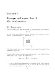
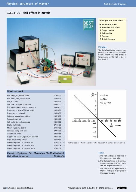
<strong>Hall</strong> voltage as a function <strong>of</strong> magnetic <strong>in</strong>duction B, us<strong>in</strong>g a copper sample.<br />
Tasks:<br />
1. The <strong>Hall</strong> voltage is measured <strong>in</strong><br />
th<strong>in</strong> copper and z<strong>in</strong>c foils.<br />
2. The <strong>Hall</strong> coefficient is determ<strong>in</strong>ed<br />
from measurements <strong>of</strong> the current<br />
and the magnetic <strong>in</strong>duction.<br />
3. The temperature dependence <strong>of</strong><br />
the <strong>Hall</strong> voltage is <strong>in</strong>vestigated on<br />
the copper sample.<br />
234 Laboratory Experiments Physics<br />
PHYWE Systeme GmbH & Co. KG · D-37070 Gött<strong>in</strong>gen
Related topics<br />
Normal <strong>Hall</strong> <strong>effect</strong>, anomalous <strong>Hall</strong> <strong>effect</strong>, charge carriers, <strong>Hall</strong><br />
mobility, electrons, defect electrons.<br />
Pr<strong>in</strong>ciple<br />
The <strong>Hall</strong> <strong>effect</strong> <strong>in</strong> th<strong>in</strong> z<strong>in</strong>c and copper foils is studied and the<br />
<strong>Hall</strong> coefficient determ<strong>in</strong>ed. The <strong>effect</strong> <strong>of</strong> temperature on the<br />
<strong>Hall</strong> voltage is <strong>in</strong>vestigated.<br />
Equipment<br />
<strong>Hall</strong> <strong>effect</strong>, Cu, carrier board 11803.<strong>00</strong> 1<br />
<strong>Hall</strong> <strong>effect</strong>, z<strong>in</strong>c, carrier board 11804.01 1<br />
Coil, 3<strong>00</strong> turns 06513.01 2<br />
Iron core, U-shaped, lam<strong>in</strong>ated 06501.<strong>00</strong> 1<br />
Pole pieces, plane, 30�30�48 mm, 2 06489.<strong>00</strong> 1<br />
Power supply 0-30 VDC/20 A, stabil 13536.93 1<br />
Power supply, universal 135<strong>00</strong>.93 1<br />
Universal measur<strong>in</strong>g amplifier 13626.93 1<br />
Teslameter, digital 13610.93 1<br />
<strong>Hall</strong> probe, tangent., prot. cap 13610.02 1<br />
Digital multimeter 07134.<strong>00</strong> 1<br />
Meter, 10/30 mV, 2<strong>00</strong> °C 07019.<strong>00</strong> 1<br />
Universal clamp with jo<strong>in</strong> 37716.<strong>00</strong> 1<br />
Tripod base -PASS- 02<strong>00</strong>2.55 1<br />
Support rod -PASS-, square, l = 250 mm 02025.55 1<br />
Right angle clamp -PASS- 02040.55 2<br />
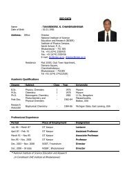
Fig. 1: Experimental set-up for the <strong>Hall</strong> <strong>effect</strong> <strong>in</strong> <strong>metals</strong>.<br />
<strong>Hall</strong> <strong>effect</strong> <strong>in</strong> <strong>metals</strong><br />
LEP<br />
<strong>5.3.03</strong><br />
-<strong>00</strong><br />
Connect<strong>in</strong>g cord, l = 750 mm, red 07362.01 6<br />
Connect<strong>in</strong>g cord, l = 750 mm, blue 07362.04 5<br />
Connect<strong>in</strong>g cord, l = 750 mm, black 07362.05 2<br />
Tasks<br />
1. The <strong>Hall</strong> voltage is measured <strong>in</strong> th<strong>in</strong> copper and z<strong>in</strong>c foils.<br />
2. The <strong>Hall</strong> coefficient is determ<strong>in</strong>ed from measurements <strong>of</strong><br />
the current and the magnetic <strong>in</strong>duction.<br />
3. The temperature dependence <strong>of</strong> the <strong>Hall</strong> voltage is <strong>in</strong>vestigated<br />
on the copper sample.<br />
Set-up and procedure<br />
The layout follows Fig. 1 and the wir<strong>in</strong>g diagram <strong>in</strong> Fig. 2.<br />
– Arrange the field <strong>of</strong> measurement on the plate midway<br />
between the pole pieces.<br />
– Carefully place <strong>Hall</strong> probe <strong>in</strong> the centre <strong>of</strong> the magnetic field.<br />
– The measur<strong>in</strong>g amplifier takes about 15 m<strong>in</strong>. to settle down<br />
free from drift and should therefore be switched on correspond<strong>in</strong>gly<br />
earlier.<br />
– To keep <strong>in</strong>terfer<strong>in</strong>g fields at a m<strong>in</strong>imal level, make the connect<strong>in</strong>g<br />
cords to the amplifier <strong>in</strong>put as short as possible.<br />
– Take the transverse current I for the <strong>Hall</strong> probe from the powersupply<br />
unit 13536.93. It can be up to 15 A for short periods.<br />
PHYWE series <strong>of</strong> publications • Laboratory Experiments • Physics • © PHYWE SYSTEME GMBH & Co. KG • D-37070 Gött<strong>in</strong>gen 25303-<strong>00</strong> 1
2<br />
LEP<br />
<strong>5.3.03</strong><br />
-<strong>00</strong><br />
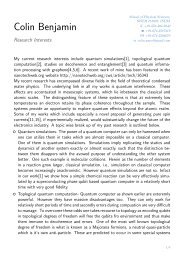
Fig. 2 Circuit diagram for the <strong>Hall</strong> <strong>effect</strong>.<br />
The <strong>Hall</strong> probe will show a voltage at the <strong>Hall</strong> contacts even <strong>in</strong><br />
the absence <strong>of</strong> a magnetic field, because these contacts are<br />
never exactly one above the other but only with<strong>in</strong> manufactur<strong>in</strong>g<br />
tolerances. Before measurements are made, this voltage<br />
must be compensated with the aid <strong>of</strong> the potentiometer as follows:<br />
– Disconnect the transverse current I.<br />
– Set the measur<strong>in</strong>g amplifier to an output voltage <strong>of</strong> 1 V, for<br />
example, by adjust<strong>in</strong>g the compensation-voltage.<br />
(h e = 10 4 Ω, amplification = 10 5 )<br />
– Connect the transverse current.<br />
– Twist the connect<strong>in</strong>g cords between hall voltage sockets<br />
and amplifier <strong>in</strong>put <strong>in</strong> order to avoid as much as possible<br />
stray voltages.<br />
– Adjust the compensat<strong>in</strong>g potentiometer, us<strong>in</strong>g a screwdriver,<br />
until the <strong>in</strong>strument aga<strong>in</strong> shows an output voltage <strong>of</strong><br />
1V.<br />
– Repeat this operation several times to obta<strong>in</strong> a precise<br />
adjustment.<br />
The determ<strong>in</strong>ation <strong>of</strong> the <strong>Hall</strong> voltage is not quite simple s<strong>in</strong>ce<br />
voltages <strong>in</strong> the microvolt range are concerned where the <strong>Hall</strong><br />
voltages are superposed by parasitic voltages such as thermal<br />
voltages, <strong>in</strong>duction voltages due to stray fields, etc. The follow<strong>in</strong>g<br />
procedure is recommended:<br />
– Set the transverse current � to the desired value.<br />
– Set the field strength B to the desired value (on the power<br />
supply, universal, 135<strong>00</strong>.93).<br />
– Set the output voltage <strong>of</strong> the measur<strong>in</strong>g amplifier to about<br />
1.5 V by adjust<strong>in</strong>g the compensation-voltage.<br />
– Us<strong>in</strong>g the ma<strong>in</strong>s switch on the power supply unit, switch the<br />
magnetic field on and <strong>of</strong>f and read the <strong>Hall</strong> voltages at each<br />
on and <strong>of</strong>f position <strong>of</strong> the switch (after the measur<strong>in</strong>g amplifier<br />
and the multi-range meter have recovered from their<br />
<strong>Hall</strong> <strong>effect</strong> <strong>in</strong> <strong>metals</strong><br />
peak values). The difference between the two values <strong>of</strong> the<br />
voltage, divided by the ga<strong>in</strong> factor 10 5 , is the <strong>Hall</strong> voltage U H<br />
to be determ<strong>in</strong>ed.<br />
Theory and evaluation<br />
If a current I flows through a strip conductor <strong>of</strong> thickness d<br />
and if the conductor is placed at right angles to a magnetic<br />
field B, the Lorentz force<br />
F �<br />
= Q (n � x B �<br />
)<br />
acts on the charge carriers <strong>in</strong> the conductor, n be<strong>in</strong>g the drift<br />
velocity <strong>of</strong> the charge carriers and Q the value <strong>of</strong> their charge.<br />
This leads to the charge carriers concentrat<strong>in</strong>g <strong>in</strong> the upper or<br />
lower regions <strong>of</strong> the conductor, accord<strong>in</strong>g to their polarity, so<br />
that a voltage – the so-called <strong>Hall</strong> voltage U H – is eventually<br />
set up between two po<strong>in</strong>ts located one above the other <strong>in</strong> the<br />
strip:<br />
U H � R H · B · I<br />
d<br />
R H is the <strong>Hall</strong> coefficient.<br />
The type <strong>of</strong> charge carrier can be deduced from the sign <strong>of</strong> the<br />
<strong>Hall</strong> coefficient: a negative sign implies carriers with a negative<br />
charge (“normal <strong>Hall</strong> <strong>effect</strong>”), and a positive sign, carriers with<br />
a positive charge (“anomalous <strong>Hall</strong> <strong>effect</strong>”). In <strong>metals</strong>, both<br />
negative carriers, <strong>in</strong> the form <strong>of</strong> electrons, and positive carriers,<br />
<strong>in</strong> the form <strong>of</strong> defect electrons, can exist. The decid<strong>in</strong>g<br />
factor for the occurrence <strong>of</strong> a <strong>Hall</strong> voltage is the difference <strong>in</strong><br />
mobility <strong>of</strong> the charge carriers: a <strong>Hall</strong> voltage can arise only if<br />
the positive and negative charge carriers have different mobilities.<br />
The measurements for copper shown <strong>in</strong> Fig. 3 are related by<br />
the expression UH � B. L<strong>in</strong>ear regression us<strong>in</strong>g the relation<br />
UH = a + bB shows these values to be represented by a<br />
straight l<strong>in</strong>e with the slope b = -0.0384 · 10 -6m2 /s and a standard<br />
deviation sb = 0.<strong>00</strong>04 · 106m/s. From this, with<br />
d =18·10 -6 m and I = 10 A, we derive the <strong>Hall</strong> coefficient<br />
RH = –(0.576 ± 0.<strong>00</strong>6) · 10-10 m3 /As.<br />
25303-<strong>00</strong> PHYWE series <strong>of</strong> publications • Laboratory Experiments • Physics • © PHYWE SYSTEME GMBH & Co. KG • D-37070 Gött<strong>in</strong>gen<br />
.
Fig. 3: <strong>Hall</strong> voltage as a function <strong>of</strong> magnetic <strong>in</strong>duction B,<br />
us<strong>in</strong>g a copper sample.<br />
The measurements shown <strong>in</strong> Fig. 4 confirm for copper the<br />
relation UH � I L<strong>in</strong>ear regression with the relation UH a + bI<br />
yields a straight l<strong>in</strong>e with slope b = – 0.770 · 10 -6 V/A and<br />
standard deviation sb = 0.<strong>00</strong>5 · 10-6 V/A. From this, with<br />
d =18· 10 -6 m and B = 0.25 T, we derive the <strong>Hall</strong> coefficient<br />
RH = – (0.554 ± 0.<strong>00</strong>4) · 10-10 m3 /As.<br />
Fig. 4: <strong>Hall</strong> voltage as a function <strong>of</strong> current I, us<strong>in</strong>g a copper<br />
sample.<br />
<strong>Hall</strong> <strong>effect</strong> <strong>in</strong> <strong>metals</strong><br />
LEP<br />
<strong>5.3.03</strong><br />
-<strong>00</strong><br />
Fig. 5: <strong>Hall</strong> voltage as a function <strong>of</strong> magnetic <strong>in</strong>duction B,<br />
us<strong>in</strong>g a z<strong>in</strong>c sample.<br />
The z<strong>in</strong>c sample shows an anomalous <strong>Hall</strong> <strong>effect</strong>, <strong>in</strong> that the<br />
<strong>Hall</strong> voltage has a positive sign. The measurements shown <strong>in</strong><br />
Fig. 5 confirm for z<strong>in</strong>c the relationship UH � B. L<strong>in</strong>ear regression<br />
us<strong>in</strong>g the expression UH = a + bB gives a straight l<strong>in</strong>e with slope<br />
b = 20.7·10 -6 m2 /s and standard deviation sb = 0.4·10-6 m/s.<br />
From this, with d = 25·10 -6 m and I = 12 A, we obta<strong>in</strong> the <strong>Hall</strong><br />
coefficient<br />
RH = (4.31 ± 0.01) · 10-11 m3 /As.<br />
Fig. 6: <strong>Hall</strong> voltage as a function <strong>of</strong> current I, us<strong>in</strong>g a z<strong>in</strong>c<br />
sample.<br />
PHYWE series <strong>of</strong> publications • Laboratory Experiments • Physics • © PHYWE SYSTEME GMBH & Co. KG • D-37070 Gött<strong>in</strong>gen 25303-<strong>00</strong> 3<br />
mV<br />
mV
LEP<br />
<strong>5.3.03</strong><br />
-<strong>00</strong><br />
The measurements shown <strong>in</strong> Fig. 6 confirm for z<strong>in</strong>c the relation<br />
UH � I. L<strong>in</strong>ear regression us<strong>in</strong>g the expression UH =<br />
a + bI gives a straight l<strong>in</strong>e with siope b = 0.40·10 6 V/A and<br />
standard deviation sb = 0.01·10 -6 V/A. From this, with<br />
d =25·10 -6 m and B = 0.25 T, we obta<strong>in</strong> the <strong>Hall</strong> coefficient<br />
RH = (4.<strong>00</strong> ± 0.01)·10 -11 m 3 /As.<br />
If the sample temperature is varied, we f<strong>in</strong>d, disregard<strong>in</strong>g disturb<strong>in</strong>g<br />
thermal voltages, that the <strong>Hall</strong> voltage <strong>in</strong> <strong>metals</strong> is not<br />
temperature dependent.<br />
4<br />
<strong>Hall</strong> <strong>effect</strong> <strong>in</strong> <strong>metals</strong><br />
If the measured values <strong>of</strong> the <strong>Hall</strong> coefficients are compared<br />
with those given <strong>in</strong> the literature<br />
(copper: R H = – 0.53·10 -10 m 3 /As; z<strong>in</strong>c: R H = 10·10 -11 m 3 /As),<br />
it is noteworthy that the values for z<strong>in</strong>c show a dist<strong>in</strong>ct difference.<br />
This, it may be presumed, is attributable to disturb<strong>in</strong>g<br />
secondary <strong>effect</strong>s particularly at the contact po<strong>in</strong>ts. Among<br />
these we may mention the Ett<strong>in</strong>ghausen <strong>effect</strong>, the Peltier<br />
<strong>effect</strong>, the Seebeck <strong>effect</strong>, the first Righi-Leduc <strong>effect</strong> and the<br />
first Ett<strong>in</strong>ghausen-Nernst <strong>effect</strong>. lt is possibly due also to<br />
impurities <strong>in</strong> the test material (99.95% purity).<br />
25303-<strong>00</strong> PHYWE series <strong>of</strong> publications • Laboratory Experiments • Physics • © PHYWE SYSTEME GMBH & Co. KG • D-37070 Gött<strong>in</strong>gen