Integrated and Modular Systems for Commercial ... - Nonstop Systems
Integrated and Modular Systems for Commercial ... - Nonstop Systems
Integrated and Modular Systems for Commercial ... - Nonstop Systems

Create successful ePaper yourself
Turn your PDF publications into a flip-book with our unique Google optimized e-Paper software.
<strong>Integrated</strong> <strong>and</strong> <strong>Modular</strong> <strong>Systems</strong><br />
<strong>for</strong> <strong>Commercial</strong> Aviation<br />
Frank M.G. Dörenberg D renberg<br />
AlliedSignal <strong>Commercial</strong> Avionics <strong>Systems</strong><br />
Redmond, WA<br />
Presented at UCLA “<strong>Modular</strong> Avionics” short course<br />
February 3-7 1997<br />
phone: (206) 885-8489 885 8489 fax: (206) 885-2061 885 2061 e-mail: mail: :frank.doerenberg@alliedsignal.com
Personal introduction<br />
• Education:<br />
– MSEE Delft Univ. of Technology (1984)<br />
– MBA Nova Southeastern Univ. (1996)<br />
• Work:<br />
–AlliedSignal Aerospace since 1984<br />
• Principal Eng on <strong>Integrated</strong> Hazard Avoidance System program (‘96-)<br />
• Prog Mgr / Staff Eng on Be-200 Integr. Avionics program (‘94-’96)<br />
• Lead systems engineer on A330/340 SFCC program (‘89-93’)<br />
• <strong>Systems</strong> engineer on Boeing 7J7 PFCS prototype program (86-’89)<br />
• Engineer on autopilot <strong>and</strong> flight simulator program (‘84-’86)<br />
• Miscellaneous:<br />
– Private pilot
<strong>Integrated</strong> <strong>and</strong> <strong>Modular</strong> <strong>Systems</strong><br />
<strong>for</strong> <strong>Commercial</strong> Aviation<br />
Frank M.G. Dörenberg renberg<br />
phone: (425) 836-4594 836 4594 e-mail: e mail: frank.doerenberg<br />
frank. doerenberg@usa usa.net .net ©1995-1997 F.M.G. Dörenberg
Personal introduction<br />
• Education:<br />
– MSEE Delft Univ. of Technology (1984)<br />
– MBA Nova Southeastern Univ. (1996)<br />
– Enrolled in PhD/EE program at University of Washington<br />
• Work:<br />
–AlliedSignal Aerospace since 1984<br />
• Principal Eng on <strong>Integrated</strong> Hazard Avoidance System program (‘96-)<br />
• Prog Mgr / Staff Eng on Be-200 Integr. Avionics program (‘94-’96)<br />
• Lead systems engineer on A330/340 SFCC program (‘89-93’)<br />
• <strong>Systems</strong> engineer on Boeing 7J7 PFCS prototype program (86-’89)<br />
• Engineer on autopilot <strong>and</strong> flight simulator program (‘84-’86)<br />
• Miscellaneous:<br />
– Private pilot<br />
©1995-1997 F.M.G. Dörenberg<br />
2
<strong>Integrated</strong> <strong>and</strong> <strong>Modular</strong> Avionics<br />
• Introduction<br />
�� Why change avionics?<br />
• Integration<br />
• <strong>Modular</strong>ization<br />
• Future .....<br />
©1995-1997 F.M.G. Dörenberg<br />
3
Aircraft<br />
Airframe<br />
Mfrs<br />
Avionics<br />
Mfrs<br />
Global aviation system<br />
- changes must be considered in overall system context-<br />
Crew<br />
Payload<br />
Airlines &<br />
Operators<br />
<strong>Integrated</strong><br />
Aviation<br />
System<br />
Gov’t &<br />
Industry<br />
Agencies<br />
Airspace Sys.,<br />
ATC/ATM<br />
Ground & Space<br />
Infrastructure<br />
Environment<br />
- many stakeholders, requirements, constraints, competition -<br />
©1995-1997 F.M.G. Dörenberg<br />
4
Engine thrust<br />
Structure<br />
& Gear<br />
Computer/<br />
Data links<br />
Cabin air<br />
press/temp<br />
Fuel Mgt<br />
Aircraft sub-systems<br />
Flight<br />
Control<br />
Phone<br />
& fax Cabin<br />
call/PA<br />
= req’d <strong>for</strong> ops in air transport system<br />
= req’d <strong>for</strong> cargo <strong>and</strong> pax com<strong>for</strong>t/well-being<br />
Electrical<br />
power<br />
Games<br />
& video<br />
Air Data<br />
Audio<br />
video<br />
Comm/Nav<br />
Surveillance<br />
Cabin<br />
lighting<br />
Cargo/bag<br />
h<strong>and</strong>ling<br />
Galleys &<br />
water/waste<br />
©1995-1997 F.M.G. Dörenberg<br />
5
Why change avionics?<br />
• Airline/Operators’ point of view:<br />
� to increase profit potential<br />
¯ lower acquisition cost<br />
¯ reduced maintenance cost<br />
¯ profitable at reduced load factor<br />
� ROI, LCC, af<strong>for</strong>dability, payback<br />
� seat-mile economics<br />
� serviceable <strong>and</strong> flyable with minimal maint. <strong>and</strong><br />
flight crew training (inc. fleet commonality)<br />
� payload, range, route structures, fuel burn (weight &<br />
volume of equipment/wiring/installation/structure)<br />
- familiar business criteria: benefits, cost, risks, profit -<br />
cont’d →<br />
©1995-1997 F.M.G. Dörenberg<br />
6
Why change avionics?<br />
• Airline/Operators’ point of view (cont’d):<br />
� safety (e.g., CFIT, WX & Windshear Radar, TCAS)<br />
� reliability, dispatchability<br />
� deferred maint., reduced unscheduled maint.<br />
� improved BITE (fault isolation, MTBUR/MTBF)<br />
� compliance with new regulations (e.g., TCAS)<br />
� increased crew & pax com<strong>for</strong>t<br />
� goal: on-time-arrival-rate = dispatchability-rate<br />
(now: 80% vs. 98%). Currently, existing capability cannot be utilized due to ATC<br />
incompatibilities.<br />
cont’d →<br />
©1995-1997 F.M.G. Dörenberg<br />
7
Why change avionics?<br />
• Airline/Operators’ point of view (cont’d):<br />
� reduced turnaround time at gate (productivity)<br />
� to support migration towards functionally flexible<br />
a/c (configuration changes) that allows:<br />
– easy incorporation of systems changes<br />
– response to changes in operational environment<br />
� to have systems that are mature at entry into service<br />
instead of years later (esp. <strong>for</strong> early ETOPS)<br />
� to reduce the cost of future software mods<br />
©1995-1997 F.M.G. Dörenberg<br />
8
Operators seek revenue enhancement<br />
•Value-added in the areas of:<br />
� operational efficiency<br />
� economic utility<br />
<strong>and</strong> above all<br />
� safety<br />
- no new technology <strong>for</strong> its own sake -<br />
ref.: Welliver, A.D.: “Higher-order technology: Adding value to an airplane,” Boeing publ., presented to Royal Aeronautical Society, London, Nov. 1991<br />
ref.: “Is new technology friend or foe?” editorial, Aerospace World, April 1992, pp. 33-35<br />
ref.: Fitzsimmons, B.: “Better value from integrated avionics?” Interavia Aerospace World, Aug. 1993, pp. 32-36<br />
ref.: ICARUS Committee: “The dollars <strong>and</strong> sense of risk management <strong>and</strong> airline safety”, Flight Safety Digest, Dec. ‘94, pp. 1-6<br />
©1995-1997 F.M.G. Dörenberg<br />
9
Airplane Operational Effectiveness →<br />
Wright Flyer<br />
Gains from avionics technology investments<br />
Individual non-avionic technologies<br />
• aerodynamics<br />
• flight controls<br />
•structures<br />
• propulsion<br />
Avionics technologies<br />
Info integration technologies<br />
1900 1950 2000<br />
- avionics is (growing) part of the equation -<br />
10<br />
©1995-1997 F.M.G. Dörenberg
Why change avionics? (cont’d)<br />
• Authorities:<br />
� ATC & ATM<br />
� ground- & space-based infrastructure<br />
� fed & int’l (de-)regulations<br />
� safety (e.g., TCAS, smoke det.)<br />
� environment<br />
• Avionics suppliers:<br />
� customer satisfaction, one-stop-shopping<br />
� cost reduction / profitability margins<br />
� technological leadership<br />
� strategic shift from BFE (commodity) → SFE<br />
� integrate competitors’ traditional products<br />
� “integrate or die”<br />
ref.: P. Parry: “Who’ll survive in the aerospace supply sector?”, Interavia, March ‘94, pp. 22-24<br />
ref.: R. Ropelewski, M. Taverna: “What drives development of new avionics?”, Interavia, Dec. ‘94, pp. 14-18 & Jan. ‘95, pp. 17-18<br />
11<br />
©1995-1997 F.M.G. Dörenberg
Why change avionics? (cont’d)<br />
• Airframe manufacturer:<br />
� customer satisfaction, product per<strong>for</strong>mance,<br />
passenger appeal<br />
� significant cost reduction over previous<br />
generation (esp. <strong>for</strong> smaller a/c, due to seat-cost considerations; e.g. 100 pax<br />
target: $35M → $20M)<br />
� reduced cycle time:<br />
– a/c development<br />
– a/c production (e.g., equipment installation & wiring)<br />
� competition (incl. from used & stored a/c, teleconf.) cont’d →<br />
12<br />
©1995-1997 F.M.G. Dörenberg
Why change avionics? (cont’d)<br />
•Airframe manufacturer (cont’d):<br />
� more dem<strong>and</strong>ing systems characteristics:<br />
– maint. deferred <strong>for</strong> 100-200 hrs or even until C-check<br />
(fault tol., spare-in-box)<br />
– fault-tolerance transparent to application s/w<br />
– brick-wall partitioned applications<br />
– all Aps & Ops software: on-board loadable/upgradeable<br />
– 100% fault detection <strong>and</strong> complete self-test (w/o test equipment)<br />
– 95% reliability over a/c life (60k-100k hrs)<br />
- more, better, cheaper, faster -<br />
ref.: P. Parry: “Who’ll survive in the aerospace supply sector?”, Interavia, March ‘94, pp. 22-24<br />
ref.: R. Ropelewski, M. Taverna: “What drives development of new avionics?”, Interavia, Dec. ‘94, pp. 14-18 & Jan. ‘95, pp. 17-18<br />
13<br />
©1995-1997 F.M.G. Dörenberg
Why change avionics? (cont’d)<br />
• Air traffic reasons:<br />
� world/regional air traffic growth<br />
� productivity improvement: traffic<br />
volume, density, flow<br />
� maintain & enhance safety<br />
• Technical & technological reasons:<br />
� airframe or engine changes<br />
� obsolescence, new capabilities<br />
- system solutions to achieve conflict-free navigation while executing<br />
the best per<strong>for</strong>mance flight-plan, moderated by passenger com<strong>for</strong>t -<br />
14<br />
©1995-1997 F.M.G. Dörenberg
Avionics business<br />
• high-tech but low volume<br />
• typ. ½-life time frames:<br />
� airframe: 25 years<br />
� electronics: 2 years<br />
� data buses: 10-15 years<br />
� HOL: ?<br />
- aircraft life-cycle: initial development, production run,<br />
through a/c lifespan after last one delivered -<br />
15<br />
©1995-1997 F.M.G. Dörenberg
Changing airtransport environment<br />
• (total) c o s t i s p a r a m o u n t<br />
• emerging markets<br />
• airlines (still) show cumulative net loss (carriers gradually<br />
returning to fin. health; ‘95 global airline operating profits $6B vs. ‘92 loss of $2B)<br />
• airline mergers, alliances, bankruptcies<br />
• airlines seek revenue enhancement <strong>and</strong> cost reductions<br />
• increasing airtraffic volume, delays<br />
• FANS/“free flight”: increased capacity, reduced<br />
separation, same or better safety<br />
• airlines & airframers want RC↓, <strong>for</strong>cing suppliers’ NRC↑<br />
• no real competition yet from video/teleconf. (biz travel)<br />
- airplanes are a commodity in rising cost environment -<br />
16<br />
©1995-1997 F.M.G. Dörenberg
Changing airtransport environment<br />
10<br />
Index 100<br />
≈ +5-6% p.a.<br />
Productivity<br />
DOC<br />
Revenue/Expense ratio<br />
Yield<br />
0<br />
1960 65 70 75 80 85 90<br />
- airline per<strong>for</strong>mance trends -<br />
ref.: Airline Business, January 1996, p. 29<br />
ref.: A. Smith: “Cost <strong>and</strong> benefits of implementing the new CNS/ATM systems”, ICAO Journal, Jan/Feb ‘96, pp. 12-15, 24<br />
≈ -2.5-2.9% p.a.<br />
17<br />
©1995-1997 F.M.G. Dörenberg
Scheduled pax (millions)<br />
1200<br />
1000<br />
800<br />
600<br />
400<br />
200<br />
Scheduled passenger traffic trends<br />
1990<br />
- World air traffic growth<br />
outpaces economic growth -<br />
1991<br />
1992<br />
1993<br />
≈ +5%/year<br />
1994<br />
1995<br />
ref.: Flight International, 3-9 January 1996, p. 27,28<br />
ref.: Boeing CAG Current Market Outlook 1995<br />
ref.: K. O’Toole: “Cycles in the sky”, Flight Int’l, 3-9 July 1996, p. 24<br />
ref.: “IATA raises five-year passenger <strong>for</strong>ecast”, Flight Int’l, 6-12 Nov 1996, p. 8<br />
Domestic<br />
1996<br />
1997<br />
≈ +7%/year<br />
1998<br />
1999<br />
Σ =1.7 B<br />
International<br />
2000<br />
- world fleet is <strong>for</strong>ecast to<br />
double over 20 years -<br />
(by 2015: ≈ 20,000 * > 50 seats )<br />
* ex CIS & Baltic states<br />
≈ +6%/year<br />
2005<br />
18<br />
©1995-1997 F.M.G. Dörenberg
5000<br />
Pax-km (billions, log-scale)<br />
1000<br />
300<br />
Scheduled-passenger <strong>and</strong> freight traffic - steady growth<br />
Passengers<br />
Freight<br />
Most likely (5.5% p.a.)<br />
Most likely (7% p.a.)<br />
ACTUAL ICAO FORECAST<br />
1985 1995 2005<br />
- potential <strong>for</strong> airspace <strong>and</strong> airport congestion -<br />
500<br />
Tonne-km (billions, log-scale)<br />
100<br />
30<br />
19<br />
©1995-1997 F.M.G. Dörenberg
Changing airtransport environment<br />
North America<br />
Intra Asia Pacific<br />
Intra Europe<br />
Trans Pacific<br />
North Atlantic<br />
Asia-Europe<br />
CIS Domestic<br />
No. Amer.-Lat. Amer.<br />
Europe-Lat. Amer.<br />
Europe-Africa<br />
Latin America<br />
CIS International<br />
source: Boeing CAG Current Market Outlook 1995<br />
1994 traffic<br />
Growth 1995-2014<br />
RPMs, billions<br />
0 200 400 600 800 1,000<br />
20<br />
©1995-1997 F.M.G. Dörenberg
Billions of 1995 US $<br />
80<br />
60<br />
40<br />
20<br />
900<br />
800<br />
700<br />
600<br />
500<br />
400<br />
300<br />
200<br />
100<br />
0<br />
<strong>Commercial</strong> aircraft sector - on the rebound<br />
Source: The Boeing Co.<br />
Average annual new aircraft investments (world fleet)<br />
‘71-’75 ‘76-’80 ‘81-’85 ‘86-’90 ‘91-’95 ‘96-’00 ‘01-’05 ‘06-’10 ‘11-’15<br />
Air transport annual deliveries<br />
Other<br />
McDonnell Douglas<br />
Airbus<br />
Boeing<br />
Source: Lehman Bros.<br />
0<br />
1958‘60‘62‘64‘66‘68‘70‘72‘74‘76‘78‘80‘82‘84‘86‘88‘90‘92‘94‘96‘98‘00‘02<br />
ref.: A.L. Velocci: “Restraint, Airline health key to stable rebound”, AW&ST, Nov. 25 1996, pp. 36-38<br />
ref.: P. Sparaco: “Airbus plans increased production rate”, AW&ST, Nov. 15 1996, pp. 48-50<br />
Percentage retired<br />
Number of aircraft<br />
100<br />
75<br />
50<br />
25<br />
0<br />
1,000<br />
750<br />
500<br />
250<br />
0<br />
20<br />
Retirement of aircraft<br />
Source: GE Capital Aviation Services<br />
25<br />
Age in years<br />
30 35<br />
Source: GE Capital Aviation Services<br />
Serviceable a/c available <strong>for</strong> sale or lease<br />
1988 1989 1990 1991 1992 1993 1994 1995 1996 1997<br />
21<br />
©1995-1997 F.M.G. Dörenberg
crew<br />
fuel maint.<br />
ownership<br />
Euro-regionals: ≈ 50% of DOC is beyond<br />
control of owner/operator (fees <strong>for</strong><br />
l<strong>and</strong>ing /ATC/ground-h<strong>and</strong>ling + fuel)<br />
Direct Operating Cost<br />
12-15%<br />
ref.: P. Condom: “Is outsourcing the winning solution?”, Interavia Aerospace World, Aug. ‘93, pp. 34-<br />
36<br />
ref.: 1992 ATA study of U.S. airlines<br />
10-15%<br />
avionics & flight contr.<br />
1/3<br />
systems<br />
22<br />
©1995-1997 F.M.G. Dörenberg
24%<br />
23%<br />
23% 30%<br />
737-300<br />
($1834/hr)<br />
16% 31%<br />
28%<br />
747-200/300<br />
($7611/hr)<br />
25%<br />
25%<br />
40%<br />
25%<br />
A320<br />
($4530/hr)<br />
11%<br />
27%<br />
32%<br />
27%<br />
Direct Operating Cost<br />
30%<br />
36%<br />
737-400<br />
($1797/hr)<br />
20%<br />
17%<br />
31%<br />
747-400<br />
($6673/hr)<br />
17%<br />
45%<br />
($3802/hr)<br />
8%<br />
11%<br />
A300-600<br />
26%<br />
24%<br />
25% 26%<br />
737-500<br />
($1607/hr)<br />
20% 25%<br />
34%<br />
DC-10-30<br />
($4306/hr)<br />
25%<br />
36%<br />
25%<br />
25%<br />
14%<br />
L-1011-1/200<br />
($3799/hr)<br />
38%<br />
14%<br />
20% 28%<br />
Fokker-100<br />
($1661/hr)<br />
27%<br />
27%<br />
27%<br />
MD-80<br />
($1825/hr)<br />
ref.: Air Transport World, Jan-May 1995<br />
ref.: “The guide to airline costs”, Aircraft Technology Engineering & Maintenance, Oct/Nov 1995, pp. 50-58<br />
19%<br />
l<strong>and</strong>ing fees etc<br />
pax services,<br />
promo,<br />
ticketing/sales<br />
G&A<br />
29%<br />
4<br />
27%<br />
DC-9-30<br />
($1612/hr)<br />
12<br />
%<br />
33%<br />
27%<br />
MD-11<br />
($4530/hr)<br />
12<br />
%<br />
11%<br />
20%<br />
15%<br />
31%<br />
34%<br />
7<br />
11%<br />
27%<br />
Worldwide airlines<br />
avg costs (1993)<br />
fuel & oil<br />
crew<br />
maint. & o'haul<br />
ownership<br />
(insurance,<br />
possession,etc.)<br />
U.S. major carriers<br />
all items in U.S.$<br />
per block hour<br />
year ending Sept. 31,'94<br />
23<br />
©1995-1997 F.M.G. Dörenberg
Aircraft<br />
Type/model<br />
B747-400<br />
B747-100<br />
L-1011<br />
DC-10-10<br />
A300-600<br />
MD-11<br />
DC-10-30<br />
B767-300ER<br />
B757-200<br />
B767-200ER<br />
A320-100/200<br />
B727-200<br />
B737-400<br />
MD-80<br />
B737-300<br />
DC-9-50<br />
B737-500<br />
B737-100/200<br />
DC-9-30<br />
F-100<br />
DC-9-10<br />
Aircraft operating statistics<br />
Number of<br />
Seats<br />
398<br />
390<br />
288<br />
281<br />
266<br />
254<br />
248<br />
221<br />
186<br />
185<br />
149<br />
148<br />
144<br />
141<br />
131<br />
124<br />
113<br />
112<br />
100<br />
97<br />
72<br />
ref.: ATA “Aircraft operating statistics - 1993”, http://www.air-transport.org<br />
Speed<br />
Airborne<br />
553<br />
520<br />
496<br />
492<br />
473<br />
524<br />
520<br />
493<br />
457<br />
483<br />
445<br />
430<br />
406<br />
422<br />
414<br />
369<br />
408<br />
387<br />
383<br />
366<br />
381<br />
Flight<br />
Length<br />
4,331<br />
3,060<br />
1,498<br />
1,493<br />
1,207<br />
3,459<br />
2,947<br />
2,285<br />
1,086<br />
2,031<br />
974<br />
686<br />
615<br />
696<br />
613<br />
320<br />
532<br />
437<br />
447<br />
409<br />
439<br />
all numbers are average<br />
Fuel<br />
gph<br />
3,356<br />
3,490<br />
2,384<br />
2,229<br />
1,938<br />
2,232<br />
2,612<br />
1,549<br />
1,004<br />
1,392<br />
771<br />
1,251<br />
775<br />
891<br />
748<br />
893<br />
708<br />
800<br />
798<br />
737<br />
740<br />
Operating<br />
Cost per hr<br />
$6,939<br />
5,396<br />
4,564<br />
4,261<br />
4,332<br />
4,570<br />
4,816<br />
3,251<br />
2,303<br />
3,012<br />
1,816<br />
2,222<br />
1,779<br />
1,793<br />
1,818<br />
1,901<br />
1,594<br />
1,757<br />
1,690<br />
1,681<br />
1,332<br />
24<br />
©1995-1997 F.M.G. Dörenberg
Big $ numbers<br />
life-time maintenance cost (ROM), example:<br />
ref.: Air Transport World, Jan-May 1995<br />
• maintenance ≈ $1200/block hour<br />
• airplane life-time ≈ 60 + k hours<br />
• maintenance-over-life ≈ $75 million<br />
- Boeing 747-400 -<br />
25<br />
©1995-1997 F.M.G. Dörenberg
Fact:<br />
Life Cycle Cost* (LCC)<br />
•inflation corrected price-tag of airplanes<br />
has increased over the years**<br />
•not completely offset by simultaneous<br />
reduction in DOC<br />
New systems & technology can only be<br />
justified if they:<br />
•take cost out of the airplane<br />
•reduce DOC<br />
•increase revenue<br />
* Net Present Value (NPV) of cost & benefit $-flows<br />
** contrary to e.g. consumer electronics<br />
26<br />
©1995-1997 F.M.G. Dörenberg
Save now <strong>and</strong> save later<br />
• increased reliability<br />
• reduced size, weight, power consumption, cooling<br />
• reduced development <strong>and</strong> production time/cost<br />
• easily upgraded/updated to new engine or airframe<br />
• easily upgraded/updated to new ATC environment<br />
• reduced crew workload<br />
• contribute to on-time departure <strong>and</strong> arrival<br />
• support accurate <strong>and</strong> simple diagnostics (w.o external test eq.)<br />
• as common as possible fleet-wide <strong>for</strong> different aircraft<br />
• mature systems at entry-into-service (esp. <strong>for</strong> ETOPS out-of-thebox)<br />
ref.: C.T. Leonard: “How mechanical engineering issues affect avionics design”, Proc. IEEE NAECON, Dayton, OH, ‘89, pp. 2043-2049<br />
27<br />
©1995-1997 F.M.G. Dörenberg
Airlines’ primary product is reliable<br />
scheduled revenue service<br />
Schedule deviations are expensive:<br />
•departure delays (up to $10k / hour)<br />
•flight cancellation (up to $50k)<br />
•in-flight diversion (up to $45k)<br />
•in terms of pax perception: incalculable<br />
- 50% of delays/cancellations caused by improper maintenance -<br />
(other causes: equipment, crew, ATC*, WX, procedures, etc.)<br />
ref.: <strong>Commercial</strong> Airline Revenue Study by GE Aircraft Engines (Jan. ‘88 - Jan. ‘92)<br />
ref.: B. Rankin, J. Allen: “Maintenance Error Decision Aid”, Boeing Airliner, April-June ‘96, pp. 20-27<br />
* mid ‘90s cost to airlines in Eu due to<br />
ATC delays est. at $1.9-2.5B p.a.<br />
28<br />
©1995-1997 F.M.G. Dörenberg
Average schedule deviation costs<br />
departure delays ($/hr)<br />
flight cancellation<br />
turn-back<br />
in-flight diversion<br />
ref.: BCAG 1993 Customer Cost Benefit Model<br />
- examples -<br />
B737<br />
$ 2k5<br />
$ 7k6<br />
$ 5k9<br />
$ 7k6<br />
B757<br />
$ 5k0<br />
$ 14k9<br />
$ 10k9<br />
$ 12k8<br />
B767<br />
$ 6k3<br />
$ 18k9<br />
$ 13k8<br />
$ 16k1<br />
B747-400<br />
$ 9k3<br />
$ 37k2<br />
$ 22k6<br />
$ 28k7<br />
29<br />
©1995-1997 F.M.G. Dörenberg
Boeing 777 Development Cost<br />
<strong>Systems</strong><br />
Structures<br />
28 %<br />
47 %<br />
(engineering & labs)<br />
5 %<br />
7 %<br />
Aero<br />
6 %<br />
7 %<br />
Misc.<br />
Payloads<br />
Propulsion<br />
ref.: P. Gartz, “<strong>Systems</strong> Engineering,” tutorial at 13th DASC, Phoenix /AZ, Oct. ‘94, & 14th DASC, Boston/MA, Nov. ‘95<br />
ref.: C. Spitzer, “Digital Avionics - an International Perspective,” IEEE AES Magazine, Vol. 27, No. 1, Jan. ‘92, pp. 44-45<br />
Dev.<br />
+ V&V<br />
Development<br />
Hardware<br />
≈ 30%<br />
½ ½<br />
V&V<br />
Software<br />
≈ 70%<br />
30<br />
©1995-1997 F.M.G. Dörenberg
<strong>Integrated</strong> <strong>Modular</strong> Avionics Architectures<br />
- more than just a “cabinet solution” -<br />
• Integration<br />
• <strong>Modular</strong>ization<br />
• St<strong>and</strong>ardization<br />
- all are key attributes of partitioning -<br />
ref: Robinson, T.H., Farmer, R., Trujillo, E.: “<strong>Integrated</strong> Processing,” presented at 14th DASC, Boston/MA, Nov. 1995<br />
ref.: L.J. Yount, K.A. Liebel, B.H. Hill: “Fault effect protection <strong>and</strong> partitioning <strong>for</strong> fly-by-wire/fly-by-light avionics systems”,<br />
Proc. 5th AIAA/IEEE Computers in Aerospace Conf., Long Beach/CA, ‘85, 10 pp.<br />
31<br />
©1995-1997 F.M.G. Dörenberg
Dependability Taxonomy<br />
Attributes Means Impairments<br />
Safety<br />
Reliability<br />
Dispatchability<br />
Maintainability<br />
Integrity<br />
Dependability<br />
Fault avoidance<br />
Fault tolerance<br />
Fault removal<br />
Fault <strong>for</strong>ecasting<br />
Faults<br />
Errors<br />
Failures<br />
- dependability: degree of justifyable reliance that can placed<br />
on a system’s delivery of correct <strong>and</strong> timely service -<br />
ref.: Int’l Federation of In<strong>for</strong>mation Processing Working Group on Dependable Computing & Fault Tolerance (IFIP WG 10.4)<br />
ref.: Prasad, D., McDermid, J., W<strong>and</strong>, I.: “Dependability terminology: similarities <strong>and</strong> differences”, IEEE AES <strong>Systems</strong> Magazine, Jan. ‘96, pp. 14-20<br />
ref.: F.J. Redmill (ed.): “Dependability of critical computer systems - 1”, 1988, 292 pp., Elsevier Publ., ISBN 1-85166-203-0<br />
ref.: A. Avizienis, J.-C. Laprie: “Dependable computing: from concepts to design diversity”, Proc. of the IEEE, Vol. 74, No. 5, May ‘86, pp. 629-638<br />
32<br />
©1995-1997 F.M.G. Dörenberg
Fault Avoidance<br />
- prevent (by construction) faults from entering into, developing in,<br />
or propagating through the system -<br />
• controlled, disciplined, consistent Sys. Eng. process<br />
• simplicity, testability, etc.<br />
• reduced parts count, interconnects & interfaces (integrate!)<br />
• st<strong>and</strong>ards, analyses, simulations, lessons-learned, V&V<br />
• partitioning (<strong>for</strong> fault containment & isolation, cert., etc.)<br />
• shielding, grounding, bonding, filtering<br />
• controlled operating environment (cooling, heatsinks, etc.)<br />
• properly select, h<strong>and</strong>le, screen, <strong>and</strong> de-rate parts<br />
• test<br />
• human factors<br />
• zero-tolerance <strong>for</strong> patch work in req’s & design<br />
• etc., etc.<br />
- must address entire product life-cycle: from inception through disposal -<br />
33<br />
©1995-1997 F.M.G. Dörenberg
Fault Tolerance<br />
- the ability of a system to sustain one or more specified faults<br />
in a way that is transparent to the operating environment -<br />
• achieved by adding & managing redundancy: one or<br />
more alternate means to per<strong>for</strong>m a particular function<br />
or flight operation<br />
• goal: only independent, multiple faults <strong>and</strong> design<br />
errors remain as reasonably possible causes of<br />
catastrophic failure conditions<br />
• fail-passive, fail-safe, fail-active are fail-intolerant<br />
• “fault tolerant” does not imply “highly dependable”,<br />
“fault free”, “ignorance tolerant”, or “full/fool proof”<br />
ref.: J.H. Lala, R. Harper: “Architectural principles <strong>for</strong> safety-critical real-time applications”, Proc. of the IEEE, Vol. 82, No. 1, Jan. ‘94, pp. 25-40<br />
ref.: D.P. Siewiorek, R.S. Swarz (eds.): “Reliable Computer <strong>Systems</strong>”, 2nd ed., Digital Press, ‘92, 908 pp., ISBN 1-55558-075-0<br />
ref.: M.R. Lyu (ed.): “Software fault tolerance”, Wiley & Sons, ‘95, 337 pp., ISBN 0-471-95068-8<br />
ref.: F.J. Redmill: “Dependability of critical computer systems - 1”, ITP Publ., ‘88, 292 pp., ISBN 1-85166-203-0<br />
ref.: B.W. Johnson: “Design <strong>and</strong> Analysis of fault tolerant systems”, Addison-Wesley, ‘89, 584 pp., ISBN 0-201-07570-9<br />
ref.: “25th Anniversary Compendium of Papers from Symposium on Fault Tolerant Computing”, IEEE Comp. Society Press, ‘96, 300 pp., ISBN 0-8186-7150-5<br />
ref.: J.C. Laprie, J. Arlat, C. Beounes, K. Kanoun, C. Hourtolle: “Hardware- <strong>and</strong> software-fault tolerance: definition <strong>and</strong> analysis of architectural solutions”, Proc. 17th<br />
Symp. on Fault Tolerant Computing, Pittsburg/PA, July ‘87, pp. 116-121
Fault Tolerance Taxonomy<br />
Fault Tolerance<br />
Redundancy<br />
• physical<br />
• temporal<br />
• data<br />
Redundancy Management<br />
Static (Fault Masking) Dynamic<br />
No fault reaction:<br />
• no fault detection<br />
• no reconfiguration<br />
Fault detection<br />
Examples of techniques: Examples of techniques:<br />
•interwoven<br />
logic<br />
• comparison (cross, voter, wrap-around)<br />
•hardwired<br />
multiple hardware • reasonableness check (rate, range, cross)<br />
redundancy<br />
• task execution monitor (a.k.a. Watch Dog)<br />
•error<br />
correcting code • checksum, parity, error detection code<br />
•majority<br />
voting (N-modular • diagnostic <strong>and</strong> built-in tests<br />
redundancy)<br />
Active<br />
• Similar<br />
• Dissimilar<br />
• adaptive voting & signal select<br />
• dynamic task reallocation<br />
• graceful degradation<br />
• n-parallel, k-out-of-n<br />
• s/w recovery (retry, rollback)<br />
• operational-mode switching<br />
Fault isolation &<br />
Reconfiguration<br />
St<strong>and</strong>by<br />
Examples of techniques: Examples of techniques:<br />
Hybrid<br />
Example of techniques:<br />
• pooled spares<br />
switch-in backup spare(s)<br />
• operating (hot, shadow)<br />
• non-operating (cold, flexed)<br />
35<br />
©1995-1997 F.M.G. Dörenberg
Fault Classifications<br />
- fault tolerance approach is driven by the number & classes of faults<br />
to protect against, as well as by criticality <strong>and</strong> risk-exposure -<br />
Criteria Fault type<br />
Activity<br />
Duration<br />
Perception<br />
Cause<br />
Intent<br />
Count<br />
Time (multiple faults)<br />
Cause (multiple faults)<br />
Latent vs. active<br />
Transient vs. permanent<br />
Symmetric vs. asymmetric<br />
R<strong>and</strong>om vs. generic<br />
Benign vs. malicious<br />
Single vs. multiple<br />
(Near-) Coincident vs. Distinct<br />
Independent vs. common-mode<br />
“Nothing in nature is r<strong>and</strong>om ... A thing appears r<strong>and</strong>om only through the<br />
incompleteness of our knowledge” -- Spinoza, Dutch philosopher 1632-1677<br />
ref.: N. Suri, C.J. Walter, M.M. Hugue (eds.): “Advances in ultra-reliable distributed systems”, IEEE Comp. Society Press, ‘95, 476 pp., ISBN 0-8186-6287<br />
36<br />
©1995-1997 F.M.G. Dörenberg
Redundancy<br />
• Attributes:<br />
� <strong>for</strong>m (physical, temporal, per<strong>for</strong>mance, data,<br />
analytical)<br />
� similarity/diversity*<br />
� level of replication<br />
� physical distribution within a/c<br />
� allocation along end-to-end path<br />
� configuration (grouping & interconnects)<br />
� redundancy management concept (static, dynamic)<br />
- more resources that required <strong>for</strong> fault-free single-thread operation -<br />
* Notes:<br />
- dissimilarity’s power is based on assumption that it makes simultaneous common-mode (generic) faults extremely improbable<br />
- dissimilarity does not reduce the probability of simultaneous r<strong>and</strong>om faults<br />
- dissimilarity provides little advantage against common-mode environmental faults (EMI, temp/vibe, power)<br />
- dissimilarity allows shift away from proving absence of generic faults, to demonstrating ability to survive them (cert. level!)<br />
- dissimilarity of design drives source of faults back to (common) requirements <strong>and</strong> system architecture<br />
- dissimilarity is fault avoidance tool, as long as independence is not compromised when fixing ambiguities or divergence<br />
37<br />
©1995-1997 F.M.G. Dörenberg
Higher reliability<br />
- will it make a difference in airline maintenance? -<br />
• frequent cause of maintenance today is not avionics LRUs, but<br />
interconnects, sensors <strong>and</strong> actuators (as much as 60%)<br />
• improving MTBUR* more important than increasing MTBF (goal:<br />
MTBUR/MTBF ratio ½ → 1)<br />
• complete system <strong>for</strong>ms a chain: high-rel is required at system level,<br />
not just at “box” level<br />
• MTBF & MTBUR ↑↑ may lead to “Avionics By The Hour”:<br />
� concept: operator leases equipment, only pays <strong>for</strong> actual hours flown<br />
� avionics mfr needs this too: sells fewer spares ⇒ (much) less profit<br />
- keep the good part on the plane -<br />
ref.: P. Seidenman, D. Spanovich: “Building a Better Black Box”, Aviation Equipment Maintenance, Feb. ‘95, pp. 34-36<br />
ref.: D. Galler, G. Slenski: "Causes of Electrical Failures," IEEE AES <strong>Systems</strong> Magazine, August 1991, pp. 3-8<br />
ref.: M. Pecht (ed.): “Product reliability, maintainability. <strong>and</strong> supportability h<strong>and</strong>book”, CRC Press, ‘95, 413 pp., ISBN 0-8493-9457-0<br />
ref.: M. Doring: “Measuring the cost of dependability”, Boeing Airliner Magazine, Jul-Sep ‘94, pp. 21-25<br />
* unit pulls on maintenance alert only, not<br />
to rotate/canibalize/swap within a fleet<br />
38<br />
©1995-1997 F.M.G. Dörenberg
Basic ways to increase system reliability<br />
• higher intrinsic reliability (components)<br />
• fault avoidance (entire life-cycle)<br />
• fault tolerance<br />
� redundant architecture*<br />
� reconfigurable architecture (LRU failure typ. only involves single component)<br />
� at box level → module level → chip level (with full BIT on-die)<br />
• integration:<br />
� reduce on-board & off-board interconnects: weakest link in<br />
the reliability chain<br />
� share resources (reduce duplication)<br />
* redundancy may increase availability, but at<br />
same time increases prob. that redundant<br />
copies are inconsistent/diverge<br />
- towards reliability of the wiring (exc. connectors) -<br />
39<br />
©1995-1997 F.M.G. Dörenberg
1<br />
System<br />
Reliability<br />
λunit = 5x10⁻⁵ Example:<br />
/h<br />
MTBFunit = 20,000 hrs<br />
N-Parallel Redundancy<br />
0.5<br />
0<br />
20k<br />
(=MTBF)<br />
40k<br />
Operating<br />
time (hrs) 100k<br />
15<br />
- brute <strong>for</strong>ce: inefficient to achieve very high system reliability - 40 37<br />
10<br />
5<br />
Number of redundant units<br />
3<br />
0.5<br />
1<br />
©1995-1997 F.M.G. Dörenberg
1<br />
System<br />
Reliability<br />
λunit = 5x10⁻⁵ Example:<br />
/h<br />
MTBFunit = 20,000 hrs<br />
N-Parallel Redundancy<br />
0.5<br />
0<br />
20k<br />
(=MTBF)<br />
40k<br />
Operating<br />
time (hrs) 100k<br />
15<br />
- goals: low cost & low redundancy but high rel. & safety - 41 38<br />
10<br />
5<br />
60k<br />
Number of redundant units<br />
3<br />
Desired<br />
region<br />
0.5<br />
100k<br />
1<br />
0.9 - 0.95<br />
©1995-1997 F.M.G. Dörenberg
MTTF n-parallel ∝ ln(n) x MTTF unit<br />
=<br />
MTTF n<br />
MTTF 1<br />
MTTF as function of redundancy level<br />
3<br />
2<br />
1<br />
from n=1 2<br />
practical limit<br />
1 5 10 15 0<br />
- diminishing returns -<br />
(curves do not account <strong>for</strong><br />
rel. penalty of complexity)<br />
Number of<br />
Parallel units<br />
0.5<br />
=∆ MTTF<br />
42<br />
©1995-1997 F.M.G. Dörenberg
Note: log-log scale<br />
F (t)<br />
2-out-of-N<br />
(t)<br />
F 2-out-of-2<br />
Parallel redundancy <strong>for</strong> system reliability<br />
0<br />
10 = 1<br />
-1<br />
10<br />
-2<br />
10<br />
-3<br />
10<br />
-4<br />
10<br />
-5<br />
10<br />
-6<br />
10<br />
-7<br />
10<br />
N=2<br />
N=4<br />
N=3<br />
F2-out-of-2 = 1<br />
F<br />
2-out-of-2<br />
0.001 0.01 0.1 1.0 10<br />
- adding redundancy is only effective <strong>for</strong> t
Redundancy<br />
Note: curves are <strong>for</strong> fail-passive configs, except those shown <strong>for</strong> simplex, cube, <strong>and</strong> n-parallel<br />
1.0<br />
R config(t)<br />
0.5<br />
1/e<br />
0<br />
dual<br />
dual-dual<br />
quad<br />
t =MTTFunit<br />
1<br />
dual-triplex<br />
triplex<br />
dual-quad<br />
2<br />
- fault-tolerant configs exhibit<br />
s-curve reliability -<br />
t<br />
MTTF unit<br />
3<br />
= MTTF<br />
cube<br />
4-parallel<br />
3-parallel<br />
2-parallel<br />
simplex<br />
44<br />
©1995-1997 F.M.G. Dörenberg
System architecture <strong>and</strong> design decisions ........<br />
MOTHER GOOSE & GRIMM<br />
45<br />
©1995-1997 F.M.G. Dörenberg
1.0<br />
R config(t)<br />
0.5<br />
1/e<br />
0<br />
dual<br />
dual-dual<br />
quad<br />
t =MTTFunit<br />
Redundancy<br />
1<br />
dual-triplex<br />
triplex<br />
dual-quad<br />
2<br />
- redundancy <strong>for</strong> fault-tolerance<br />
<strong>and</strong> extended system reliability -<br />
region of<br />
practical use<br />
t<br />
MTTF unit<br />
3<br />
= MTTF<br />
cube<br />
4-parallel<br />
3-parallel<br />
2-parallel<br />
simplex<br />
46<br />
©1995-1997 F.M.G. Dörenberg
1.0<br />
Rconfig(t)<br />
0.9<br />
0.8<br />
dual<br />
Redundancy<br />
2-p<br />
simplex<br />
triplex<br />
dual-dual<br />
quad<br />
3-p<br />
dual-triple<br />
cube<br />
4-p<br />
dual-quad<br />
0.5 1.0<br />
MTTFunit<br />
- region of practical use, enlarged -<br />
t<br />
47<br />
©1995-1997 F.M.G. Dörenberg
Relative MTTF of various configurations<br />
Simplex<br />
Dual<br />
Triplex<br />
Quad<br />
Dual-Dual<br />
Dual-Triplex<br />
Dual-Quad<br />
Triple-Dual<br />
Quad-Dual<br />
Triple-Triple<br />
2-Parallel<br />
3-Parallel<br />
4-Parallel<br />
Cube<br />
note: MTTFs solely based on time-integration of reliability funct., <strong>and</strong> do not reflect system complexity; Markov analysis may give different result.<br />
48<br />
©1995-1997 F.M.G. Dörenberg
Simplex<br />
Dual<br />
Triplex<br />
Quad<br />
Dual-Dual<br />
Dual-Triplex<br />
Dual-Quad<br />
Triple-Dual<br />
Quad-Dual<br />
Triple-Triple<br />
2-Parallel<br />
3-Parallel<br />
4-Parallel<br />
Cube<br />
Mission times of several configurations<br />
Time-to-R= 0.997 Time-to-R= 0.95 Time-to-R= 0.5 (Median TTF)<br />
49<br />
©1995-1997 F.M.G. Dörenberg
note: output wraparounds not shown<br />
“Cube” configuration concept<br />
λ 1 λ 1 λ 1 λ b<br />
λ a λ a λ a<br />
λ b<br />
λ c λ c λ c<br />
3-parallel “cube”<br />
increased number of<br />
paths through the system<br />
λ b<br />
λ a<br />
λ b<br />
λ a<br />
λ c λ c λ c<br />
“optimized cube”<br />
if no single-thread ops., then<br />
don’t need 3 output modules<br />
- use resources more efficiently: do not discard entire lane if only part fails -<br />
ref.: M. Lambert: “Maintenance-free avionics offered to airlines”, Interavia, Oct. ‘88, pp. 1088-<br />
λ b<br />
λ b<br />
50<br />
©1995-1997 F.M.G. Dörenberg
Integration is necessary because....<br />
• Increase operational effectiveness via integration of<br />
in<strong>for</strong>mation (e.g., safety)<br />
• Must work smarter, not harder:<br />
– system reliability increases only slowly as redundancy level increases:<br />
∝ ln(n)<br />
– above n = 3, adding redundancy is not effective<br />
– “brute <strong>for</strong>ce” will not get us there<br />
• Unit-reliability is more powerful than redundancy<br />
level in achieving high system reliability<br />
- Fit-<strong>and</strong>-<strong>for</strong>get system reliability (based on conventional redundancy)<br />
implies units with reliability of today’s components (λ ≈ 10 -7 /h) −<br />
51<br />
©1995-1997 F.M.G. Dörenberg
Integration of what?<br />
• hardware, software, mechanical elements<br />
• data buses, RF apertures<br />
• related, interacting, closely associated, similar functions<br />
& controls (reduce duplication)<br />
• distributed in<strong>for</strong>mation<br />
� e.g., fusion <strong>for</strong> more meaningful pilot info (“smart alerting”, EMACS)<br />
� e.g., improve per<strong>for</strong>mance (flight + thrust control, ECS)<br />
• displays, controls, LRUs (esp. single-thread)<br />
• BIT<br />
� increase fault isolation accuracy<br />
� reduce NFF/CND/RETOK* from 50% to < 10%<br />
• organizations, people<br />
• entire aviation system<br />
ref.: P. Gartz: “Trends in Avionics <strong>Systems</strong> Architecture”, presented at the 9th DASC, Virginia Beach/VA, Oct. ‘90, 23 pp.<br />
ref.: Avionics <strong>Systems</strong> Eng. & Maint. Committee (ASEMC) of the Air Transport Ass’n (ATA)<br />
ref.: Avionics Magazine, Feb. 1996, p. 12<br />
* ATA est. NFF cost to US airline<br />
industry ≈ $100M p.a., avg $800 per<br />
removal (labor, shipping, sparing)<br />
52<br />
©1995-1997 F.M.G. Dörenberg
Integration trend: Multi-Mode Receiver (MMR)<br />
• ICAO philosophy change (Comm/Ops meeting,<br />
Montreal ‘95):<br />
� from: single-system (e.g., VOR/DME) st<strong>and</strong>ard,<br />
ensuring int’l uni<strong>for</strong>mity & compatibility<br />
� to: st<strong>and</strong>ardizing on 3 quite different approach<br />
aids (ILS, MLS, GNSS*)<br />
� so: CAAs, airports, operators free to choose one<br />
or more<br />
� <strong>and</strong>: world aviation authorities should promote<br />
the use of Multi-Mode Receivers (MMRs) or<br />
equivalent avionics<br />
* ICAO: GNSS > GPS (e.g., GNS+GLONASS,<br />
to ensure complete redundancy, esp. in l<strong>and</strong>ing ops.)<br />
ref.: W. Reynish: “Three systems, One st<strong>and</strong>ard?”, Avionics Magazine, Sept. ‘95, pp. 26-28<br />
ref.: D. Hughes: “USAF, GEC-Marconi test ILS/MLS/GPS receiver”, AW&ST, Dec. 4 ‘95, pp. 96<br />
ref.: R.S. Prill, R. Minarik: “Programmable digital radio common module prototypr”, Proc. 13th DASC, Phoenix/AZ, Nov. ‘94, pp. 563-567<br />
53<br />
ref.: ARINC-754/755 (analog/digital MMR), ARINC-756 (GNLU)<br />
©1995-1997 F.M.G. Dörenberg
LRUs<br />
Integration trend<br />
FMGD<br />
System<br />
On<br />
Chip<br />
1970s 1980s 1990s 2000-2010<br />
-2<br />
-4<br />
-5<br />
λ ~10 λ ~10<br />
total<br />
total<br />
λ ~ 2x10<br />
total<br />
λ total<br />
point-to-point analog<br />
interconnect<br />
single-thread systems<br />
ARINC-429 digital<br />
interconnect<br />
single-thread LRUs<br />
ARINC-629 digital data<br />
bus between LRUs<br />
ARINC-659 backplane<br />
bus between LRMs<br />
fault tolerant LRUs<br />
high-speed fiber optic<br />
comm. between systems<br />
fault tolerant cards<br />
system level redundancy box level redundancy card level redundancy chip level redundancy<br />
ref: BCAC/J. Shaw<br />
~10<br />
-7<br />
54<br />
©1995-1997 F.M.G. Dörenberg
Integration issues<br />
• “integrated system” is not a “package deal”<br />
• airline:<br />
� no more option to pick favorite supplier <strong>for</strong> each federated LRU<br />
� but gets improved availability, reduced sparing & LCC<br />
• as levels of (functional) integration increase → more stringent<br />
availability & integrity req’s than <strong>for</strong> more distributed<br />
implementation<br />
• if integration requires fault-tolerance (= redundancy), some of the<br />
gains from reduced duplication are lost<br />
• compared to “conventional” LRUs, cabinet/LRM solutions pose<br />
challenge to effective shielding/bonding <strong>for</strong> EMI/Lightning<br />
protection<br />
• partitioning provides change/growth flexibility: only re-certify<br />
changed areas<br />
55<br />
©1995-1997 F.M.G. Dörenberg
Integration issues (cont’d)<br />
• loss of a shared resource affects multiple functions → potential <strong>for</strong><br />
single-point/common-mode failure due to contaminated data flow,<br />
control flow, resource:<br />
� fault tolerance required to meet availability & integrity req’s<br />
� partitioning must be part of architecture <strong>and</strong> independent of application<br />
software<br />
� increased importance of FMEA, FHA, etc.<br />
• mixed levels of criticality: certify at highest level, or certify the<br />
partitioning protection.<br />
• criticality of the “whole” may be higher than that of “st<strong>and</strong>-alone”<br />
parts due to effects of loss (3x “essential” → “critical” ?)<br />
• technology readiness (risk): development of fault-tolerant integrated<br />
architectures drives a/c level schedules (be mature at a/c program go-ahead)<br />
56<br />
©1995-1997 F.M.G. Dörenberg
Fault Tolerance <strong>for</strong> Safety, Reliability,<br />
Larson<br />
NO unpleasant surprises!<br />
Dispatchability:<br />
57<br />
©1995-1997 F.M.G. Dörenberg
FAA/JAA Hazard Severity Classification<br />
Catastrophic<br />
Hazardous /<br />
Severe-Major<br />
Major<br />
Minor<br />
*<br />
Failure<br />
Condition<br />
Classification<br />
No Effect<br />
FAR /JAR<br />
25-1309<br />
AC25.1309-1A<br />
Effect of failure condition on<br />
aircraft <strong>and</strong> occupants<br />
• Prevents continued safe flight <strong>and</strong> l<strong>and</strong>ing<br />
• Loss of aircraft<br />
• Multiple deaths<br />
• Large reduction in safety margins or functional capabilities<br />
• Difficult <strong>for</strong> crew to cope with adverse operating conditions, <strong>and</strong><br />
cannot be relied upon to per<strong>for</strong>m tasks accurately & completely<br />
• Some passengers seriously injured (potentially fatal)<br />
• Significant reduction in safety margins or functional capabilities<br />
• Significant increase in crew workload or conditions impairing<br />
crew efficiency<br />
• Some passengers injured<br />
• Slight reduction of safety margins or functional capabilities<br />
• Slight increase in crew workload, well within capabilities<br />
• Operational limitations, diversions, flight plan changes<br />
• Inconvenience to passengers<br />
• No effect on operational capability of aircraft<br />
• No increase in crew workload<br />
• Concern, nuisance<br />
*determined by per<strong>for</strong>ming Funct. Hazard Assess. (FHA)<br />
- hazard severity: worst credible known/potential consequence of mishap -<br />
58<br />
©1995-1997 F.M.G. Dörenberg
Quant.<br />
Prob.<br />
1<br />
10-3<br />
10-5<br />
10-7<br />
10-9<br />
0<br />
FAA/JAA Probability Ranges<br />
JAR<br />
Qualitative<br />
Frequent<br />
Reasonably<br />
Probable<br />
Remote<br />
Extremely<br />
Remote<br />
FAR<br />
Qualitative<br />
Probable<br />
Improbable<br />
Extremely Improbable<br />
AMJ 25.1309<br />
* *<br />
AC 25.1309-1A<br />
- qualitative <strong>and</strong> quantitative -<br />
Qualitative Probability<br />
several times during operational<br />
life of each airplane<br />
occasionally during total<br />
operational life of all<br />
airplanes of particular type<br />
not expected to occur in entire<br />
fleet operational life<br />
* FAR & JAR are being harmonized<br />
59<br />
©1995-1997 F.M.G. Dörenberg
Hazard<br />
Probability<br />
Probable<br />
Improbable<br />
Extremely<br />
Improbable<br />
FAA/JAA Criticality Index<br />
Unacceptable<br />
Unacceptable<br />
Acceptable<br />
unless single failure<br />
Critical<br />
(A)<br />
failure contributes to, or<br />
causes a failure condition<br />
which would prevent<br />
continued safe flight <strong>and</strong><br />
l<strong>and</strong>ing<br />
Unacceptable<br />
Conditionally<br />
Acceptable<br />
Acceptable<br />
unless single failure<br />
Essential (B)<br />
failure contributes to, or<br />
causes a failure condition<br />
which would significantly<br />
impact airplane safety or<br />
crew ability to cope with<br />
adverse operating condit.<br />
Acceptable<br />
Acceptable<br />
Acceptable<br />
Non-Essential<br />
(C)<br />
failure would not<br />
contribute<br />
to, or causes a failure<br />
condition which would<br />
significantly impact airplane<br />
safety or crew ability to<br />
cope with adverse condit.<br />
- allowed combinations of hazard severity <strong>and</strong> probability -<br />
Equipment<br />
Category<br />
60<br />
©1995-1997 F.M.G. Dörenberg
Failure System<br />
Condition Design<br />
Assurance<br />
Classification Level<br />
Catastrophic<br />
Hazardous /<br />
Severe-Major<br />
Major<br />
Minor<br />
No Effect<br />
FAR /JAR<br />
AC/AMJ<br />
25.1309<br />
FAA/JAA Hazard Index<br />
A<br />
B<br />
C<br />
D<br />
E<br />
DO-178B<br />
DO-180<br />
ARP 4754<br />
Probability<br />
Objective<br />
extremely<br />
improbable<br />
extremely<br />
remote<br />
remote<br />
none<br />
none<br />
Failure Objectives<br />
Fail-safe Single-point<br />
Failures<br />
required<br />
may be<br />
required<br />
may be<br />
required<br />
not<br />
required<br />
not<br />
required<br />
precluded<br />
no<br />
requirement<br />
no<br />
requirement<br />
no<br />
requirement<br />
no<br />
requirement<br />
- hazard: potential/existing unplanned condition<br />
that can result in death, injury, illness, damage, loss -<br />
ref.: H.E. Rol<strong>and</strong>, B. Moriarty: “System safety engineering <strong>and</strong> management”, 2nd ed., Wiley & Sons, ‘90, 367 pp., ISBN 0-471-61816-0<br />
61<br />
©1995-1997 F.M.G. Dörenberg
“Don’t worry!<br />
Nothing can go wrong ....<br />
go wrong.....<br />
go wrong....”<br />
Hal, 2001: A Space Odyssey<br />
62<br />
©1995-1997 F.M.G. Dörenberg
Electro-Magnetic Interference (EMI) - sources<br />
LIGHTNING<br />
RADIO<br />
FREQUENCY<br />
HUMAN<br />
ELECTRO-<br />
STATIC<br />
DISCHARGE<br />
ELECTRONIC<br />
UNIT & WIRING<br />
Aircraft radios<br />
AM/FM radio<br />
TV stations<br />
Ground radar<br />
POWER DISTURBANCE<br />
ref.: Clarke, C.A., Larsen, W.A.: “Aircraft Electromagnetic Compatibility”, DOT/FAA/CT-86/40, June 1987<br />
ref.: Shooman, L.M.: “A study of occurrence rates of EMI to aircraft with a focus on HIRF”, Proc. DASC-93, pp. 191-194<br />
ref.: RTCA Document DO-233 “Portable Electronic Devices Carried On Board Aircraft, Aug. ‘96<br />
Graphics adapted from: J.A. Schofield: “European st<strong>and</strong>ards shine spotlight on EMI”, Design News, 9-25-1995, pp. 58-60<br />
PERSONAL<br />
ELECTRONIC<br />
DEVICES<br />
cell phones<br />
laptop PCs<br />
CD players<br />
games<br />
CONDUCTED EMISSIONS<br />
Aircraft power 400 Hz E/M<br />
Bus switching<br />
Inductive load switching<br />
Switching regulators<br />
Computer clock & data<br />
Analog signal coupling<br />
RADIATED<br />
EMISSIONS<br />
- average EMI incident occurrence rate ≈ 5x10 -3 per flight -<br />
63<br />
©1995-1997 F.M.G. Dörenberg
EMC: Electro-Magnetic Compatibility<br />
• increased EMI-susceptibility of electronic devices:<br />
� integration: higher chip density; (deep) sub-micron feature sizes<br />
� reduced operating voltages<br />
� lower levels of energy cause upsets<br />
• increased reliance on digital computers (<strong>for</strong> flight-critical<br />
functions) that contain EMI-susceptible devices<br />
• higher clock speeds:<br />
� reduced susceptibility: PCB tracks become transmission lines<br />
� but absolute b<strong>and</strong>width <strong>for</strong> decent signal shapes goes up (≈10xfc)<br />
� though b<strong>and</strong>width pushed into range with fewer x-mitters (civil)<br />
• continued proliferation of EM transmitters (incl. PEDs),<br />
<strong>and</strong> increase in EM power<br />
• reduced inherent Faraday-cage protection: increasing<br />
amounts of non-metallic airframe sections<br />
ref.: C.A. Clarke, W.E. Larsen: “Aircraft Electromagnetic Compatibility”, Feb. ‘89, 155 pp., DOT/FAA/CT-88/10; same as Chapt. 11 of Dig. <strong>Systems</strong> Validation H<strong>and</strong>book Vol.<br />
II<br />
ref.:G.L. Fuller: “Underst<strong>and</strong>ing HIRF - High Intensity Radiated Fields”, Avionics Comm. Publ., Leesburg/VA, ‘95, 123 pp., ISBN 1-885544-05-7<br />
64<br />
ref.: M.L. Shooman: “A study of occurrence rates of EMI to aircraft with a focus on HIRF”, Proc. 12th DASC, Seattle/WA, Oct. ‘93, pp. 191-194<br />
©1995-1997 F.M.G. Dörenberg
Req's <strong>for</strong> Fault Avoidance<br />
(incl. Containment)<br />
<strong>and</strong> Robustness<br />
Requirements Taxonomy<br />
• Mission<br />
• Safety<br />
• Reliability<br />
• Dispatchability<br />
Requirements<br />
• Availability<br />
• Functionality<br />
• Per<strong>for</strong>mance<br />
• Operational<br />
Req's <strong>for</strong> Fault Tolerance<br />
Req's <strong>for</strong> Redundancy<br />
• Fault masking<br />
• Fault detection<br />
• Fault isolation<br />
• Fault recovery<br />
• etc.<br />
• Maintenance<br />
• Cost<br />
• Certificability<br />
• etc.<br />
Req's <strong>for</strong> Redundancy Management<br />
Req's <strong>for</strong> Integrity Checks<br />
65<br />
©1995-1997 F.M.G. Dörenberg
<strong>Modular</strong>ity issues<br />
• modularization decreases the size of the Line Removable<br />
Item from LRU “box” to LRM “module”<br />
• flexibility: add or remove functions <strong>and</strong> hardware<br />
• flexibility: change architecture (configure & reconfigure)<br />
• permits management of obsolescence: piece-meal update<br />
on modular basis, as technology & economics justify<br />
• reconfigurability, expansion to meet future needs by<br />
adding modules<br />
• facilitates fault tolerance (N+1 redundancy)<br />
- module = building block -<br />
66<br />
©1995-1997 F.M.G. Dörenberg
St<strong>and</strong>ardization issues<br />
• “generic”, can be used across variety of functions<br />
• economies of scale (production volume, recurring cost)<br />
• fewer unique designs <strong>and</strong> parts, re-use<br />
• fewer part numbers:<br />
– smaller number of spares:<br />
PL = exp(-N) .Σ<br />
1/k N<br />
m!<br />
– spares acquisition (may be higher) & holding cost<br />
– logistics, supportability<br />
– documentation, configuration management<br />
– training, test equipment<br />
• “overkill” penalty <strong>for</strong> being “universal” (must support<br />
highest system req’s → higher design assurance level)<br />
kit<br />
- st<strong>and</strong>ardization ~ commonality -<br />
NS<br />
m=0<br />
m<br />
67<br />
©1995-1997 F.M.G. Dörenberg
Hardware<br />
Resources<br />
Processor core<br />
Memory<br />
Common I/O *<br />
BIT hardware<br />
Power supply<br />
Chassis<br />
Unique I/O *<br />
Typical st<strong>and</strong>-alone LRU<br />
* with EMI protection<br />
Software<br />
Resources<br />
Operating<br />
System<br />
I/O processing<br />
<strong>and</strong> monitoring<br />
BIT <strong>and</strong> Maint.<br />
functions<br />
Application<br />
Unique BIT<br />
ref.: M.J. Morgan: “<strong>Integrated</strong> <strong>Modular</strong> Avionics <strong>for</strong> Next-Generation <strong>Commercial</strong> Aircraft”, IEEE AES <strong>Systems</strong> Magazine, Aug. ‘91, pp. 9-12<br />
ref.: D. Hart: “<strong>Integrated</strong> <strong>Modular</strong> Avionics - Part I - V”, Avionics, May-Nov. 1991<br />
Common<br />
Unique<br />
68<br />
©1995-1997 F.M.G. Dörenberg
Resources<br />
Hardware Software<br />
St<strong>and</strong>ard<br />
<strong>and</strong><br />
common<br />
functions<br />
Unique<br />
functions<br />
Integration of multiple LRUs<br />
St<strong>and</strong>ard<br />
<strong>and</strong><br />
common<br />
functions<br />
Unique<br />
functions<br />
LRU-2<br />
LRU-1<br />
INTEGRATION<br />
LRU-3<br />
Hardware<br />
Resources<br />
Processor Core<br />
Memory<br />
Shared I/O *<br />
BIT hardware<br />
Power Supply<br />
Chassis<br />
Unique I/O *<br />
Unique I/O *<br />
Unique I/O *<br />
Software<br />
Resources<br />
Operating<br />
System<br />
I/O processing<br />
& monitoring<br />
BIT <strong>and</strong> Maint.<br />
functions<br />
Application-1<br />
Unique BIT<br />
Application-2<br />
Unique BIT<br />
Application-3<br />
Unique BIT<br />
69<br />
©1995-1997 F.M.G. Dörenberg
Resources<br />
Hardware Software<br />
St<strong>and</strong>ard<br />
<strong>and</strong><br />
common<br />
functions<br />
Unique<br />
functions<br />
Integration of multiple LRUs<br />
St<strong>and</strong>ard<br />
<strong>and</strong><br />
common<br />
functions<br />
Unique<br />
functions<br />
LRU-2<br />
LRU-1<br />
INTEGRATION<br />
LRU-3<br />
st<strong>and</strong>ardize<br />
via end-to-end digitalization<br />
from sensors to actuators<br />
Hardware<br />
Resources<br />
Processor Core<br />
Memory<br />
Shared I/O *<br />
BIT hardware<br />
Power Supply<br />
Chassis<br />
Unique I/O *<br />
Unique I/O *<br />
Unique I/O *<br />
Software<br />
Resources<br />
Operating<br />
System<br />
I/O processing<br />
& monitoring<br />
BIT <strong>and</strong> Maint.<br />
functions<br />
Application-1<br />
Unique BIT<br />
Application-2<br />
Unique BIT<br />
Application-3<br />
Unique BIT<br />
70<br />
©1995-1997 F.M.G. Dörenberg
Integration & <strong>Modular</strong>ization<br />
• LRUs interact → interconnects<br />
• Integration of LRUs → fewer interconnects:<br />
� connectors (failure prone <strong>and</strong> very expensive if high pin-count)<br />
� wiring (weight)<br />
� communication h/w at both ends<br />
� communication s/w at both ends<br />
71<br />
©1995-1997 F.M.G. Dörenberg
Integration & <strong>Modular</strong>ization<br />
• LRU integration reduces overlap/duplication<br />
of h/w <strong>and</strong> s/w functions:<br />
� processor core<br />
� I/O (un)<strong>for</strong>matting<br />
� input signal monitoring & selection<br />
� parameter derivation<br />
� hardware monitoring<br />
� EMI/Lightning protection<br />
� power supply<br />
� faul reporting, maintenance, BIT<br />
72<br />
©1995-1997 F.M.G. Dörenberg
O/S<br />
I/O<br />
Maint.<br />
BIT<br />
Appl.<br />
Total<br />
CPU<br />
I/O<br />
Power<br />
Bus<br />
Chass.<br />
Total<br />
Effect of integrating additional functions - exercise<br />
Federated <strong>Integrated</strong><br />
5%<br />
20%<br />
10%<br />
20%<br />
45%<br />
100%<br />
15%<br />
20%<br />
10%<br />
30%<br />
25%<br />
100%<br />
-- - ≈ + ++<br />
-- - ≈ + ++<br />
IMA enclosure + 1 st application<br />
Rel. hardware cost Rel. software complexity<br />
O/S<br />
I/O<br />
Maint.<br />
BIT<br />
Appl.<br />
Total<br />
CPU<br />
I/O<br />
Power<br />
Bus<br />
Chass.<br />
Total<br />
Federated <strong>Integrated</strong><br />
5%<br />
20%<br />
10%<br />
20%<br />
45%<br />
100%<br />
15%<br />
20%<br />
10%<br />
30%<br />
25%<br />
100%<br />
-- - ≈ + ++<br />
-- - ≈ + ++<br />
Each additional application<br />
Rel. hardware cost Rel. software complexity<br />
73<br />
©1995-1997 F.M.G. Dörenberg
Effect of integrating additional functions - (gu)es(s)timates<br />
O/S<br />
I/O<br />
Maint.<br />
BIT<br />
Appl.<br />
Total<br />
CPU<br />
I/O<br />
Power<br />
Bus<br />
Chass.<br />
Total<br />
source: BCAG (adapted)<br />
Federated <strong>Integrated</strong><br />
5%<br />
20%<br />
10%<br />
20%<br />
45%<br />
100%<br />
15%<br />
20%<br />
10%<br />
30%<br />
25%<br />
100%<br />
+50%<br />
same<br />
+30%<br />
same<br />
same<br />
+2/3<br />
same<br />
double<br />
double<br />
+20%<br />
7%<br />
20%<br />
13%<br />
25%<br />
45%<br />
110%<br />
25%<br />
20%<br />
20%<br />
60%<br />
30%<br />
155%<br />
IMA enclosure + 1 st application<br />
Rel. software complexity<br />
Rel. hardware cost<br />
O/S<br />
I/O<br />
Maint.<br />
BIT<br />
Appl.<br />
Total<br />
CPU<br />
I/O<br />
Power<br />
Bus<br />
Chass.<br />
Total<br />
Federated <strong>Integrated</strong><br />
5%<br />
20%<br />
10%<br />
20%<br />
45%<br />
100%<br />
15%<br />
20%<br />
10%<br />
30%<br />
25%<br />
100%<br />
half<br />
half<br />
same<br />
-1/4<br />
half<br />
-80%<br />
10%<br />
5%<br />
45%<br />
60%<br />
15%<br />
5%<br />
5%<br />
25%<br />
Each additional application<br />
Rel. hardware cost Rel. software complexity<br />
74<br />
©1995-1997 F.M.G. Dörenberg
Effect of integrating additional functions - (gu)es(s)timates<br />
Rel. hardware cost<br />
Rel. software complexity<br />
source: BCAG (adapted)<br />
100%<br />
155%<br />
Federated <strong>Integrated</strong><br />
100%<br />
110%<br />
Federated <strong>Integrated</strong><br />
IMA enclosure + 1 st application<br />
Rel. hardware cost<br />
Rel. software complexity<br />
100%<br />
100%<br />
- the more you integrate, the “better” -<br />
assumes integration of related<br />
functions of equal size &<br />
complexity; 25% error margin<br />
25%<br />
Federated <strong>Integrated</strong><br />
60%<br />
Federated <strong>Integrated</strong><br />
Each additional application<br />
75<br />
©1995-1997 F.M.G. Dörenberg
assumes integration of related<br />
functions with equal size/complexity<br />
Normalized softwar esize →<br />
10<br />
8<br />
6<br />
4<br />
2<br />
1<br />
source: BCAG (adapted)<br />
Advantages of integrating additional functions<br />
Federated<br />
1 2 4 6 8 10<br />
Number of system functions →<br />
25% error bar<br />
<strong>Integrated</strong><br />
- not effective if only integrating 2 or 3 functions -<br />
Normalized hardware cost →<br />
10<br />
8<br />
6<br />
4<br />
2<br />
1<br />
Federated<br />
<strong>Integrated</strong><br />
1 2 4 6 8 10<br />
Number of system functions →<br />
25% error bar<br />
76<br />
©1995-1997 F.M.G. Dörenberg
assumes integration of related<br />
functions with equal size/complexity<br />
Normalized softwar esize →<br />
10<br />
8<br />
6<br />
4<br />
2<br />
1<br />
<strong>Integrated</strong><br />
1 2 4 6 8 10<br />
Number of system functions →<br />
- ??????????? -<br />
Well……..<br />
Normalized hardware cost →<br />
10<br />
8<br />
6<br />
4<br />
2<br />
1<br />
⌠<br />
⌡<br />
Federated<br />
<strong>Integrated</strong><br />
1 2 4 6 8 10<br />
Number of system functions →<br />
Cost of cert., partitioning,config mgt<br />
77<br />
©1995-1997 F.M.G. Dörenberg
Integration & <strong>Modular</strong>ization<br />
• <strong>Modular</strong>ization reduces duplication of<br />
product development ef<strong>for</strong>t:<br />
� specification<br />
� design<br />
� integration <strong>and</strong> test<br />
� qualification<br />
� V&V, certification<br />
� part numbers<br />
� time-to-market<br />
� program risk<br />
� $$$<br />
78<br />
©1995-1997 F.M.G. Dörenberg
Integration & <strong>Modular</strong>ization<br />
• Other factors:<br />
� Natural tendency: trend towards more<br />
interaction & coordination between<br />
systems (flight & thrust control, safety, com/nav, etc.)<br />
� sub-optimal use of (now) distributed<br />
data/knowledge<br />
� NFF/CND/RETOK, MTBUR/MTBF<br />
typically at 50%<br />
� FANS (com/nav/surveillance)<br />
79<br />
©1995-1997 F.M.G. Dörenberg
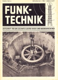
A historical note<br />
“<strong>Modular</strong> electronics” dates back to several<br />
German military radios of the late 1930s!<br />
• modules<br />
• chassis with “backplane”<br />
• st<strong>and</strong>ardization of parts<br />
• BIT<br />
- reasons: technical, logistical, maintenance,<strong>and</strong> manufacturing-<br />
ref.: H.-J. Ellissen: “Funk- u. Bordsprechanlagen in Pantzerfahrzeugen” Die deutschen Funknachrichtenanlagen bis 1945, B<strong>and</strong> 3, Verlag Molitor, 1991, ISBN 3-928388-01-0<br />
ref.: D. Rollema:: “German WW II Communications Receivers - Technical Perfection from a Nearby Past”, Part 1-3, CQ, Aug/Oct 1980, May 1981<br />
80<br />
ref.: A. O. Bauer: “Receiver <strong>and</strong> transmitter development in Germany 1920-1945”, presented at IEE Int’l Conf. on 100 Years of Radio, London, Sept. 1995<br />
©1995-1997 F.M.G. Dörenberg
German “WW II” radios<br />
• Modules:<br />
� die-cast Alu-Mg alloy module* <strong>for</strong> each stage<br />
� completely enclosed & shielded, with internally<br />
shielded compartments<br />
� generously applied decoupling (fault avoidance)<br />
� mechanically & electrically very stable<br />
� easily installed/removed w. 90° lock-screws (maint.)<br />
� simple (manufacturability: strategically distributed, no high skills)<br />
ref.: Telefunken GmbH: “Luftboden-Empf-Programm 2-7500 m für die Bodenausrüstung der deutschen Luftwaffe”, Berlin, May<br />
* from mid-1943 on, only Goering’s Luftwaffe got Alu;<br />
Army/Navy got Zn alloy<br />
81<br />
©1995-1997 F.M.G. Dörenberg
German “WW II” radios<br />
• Chassis <strong>and</strong> “Backplane”:<br />
� modules plug into chassis<br />
� motherboard / backplane module<br />
(E52 “Köln” receiver, 1943)<br />
� 3-D arrangement<br />
� assy slides into sturdy (!) cabinet<br />
82<br />
©1995-1997 F.M.G. Dörenberg
German “WW II” radios<br />
• Receiver st<strong>and</strong>ardization:<br />
� 40 kHz - 150 MHz covered with 4 radios<br />
with identical <strong>for</strong>m, fit, operation<br />
• Parts st<strong>and</strong>ardization:<br />
� 1 or 2 st<strong>and</strong>ard types of tubes per radio<br />
– Lorenz Lo 6 K 39a: 6x RV12P2000<br />
– Telefunken Kw E a: 11x RV2P800<br />
– FuSprech. f.: 6x RV12P2000 + 1x RL12P10 (RX),<br />
<strong>and</strong> 1x RV12P2000 + 2x RL12P10 (TX)<br />
– tricky circuitry<br />
- spares logistics, test equipment -<br />
83<br />
©1995-1997 F.M.G. Dörenberg
• BIT:<br />
German “WW II” radios<br />
� switchable meter <strong>for</strong> V anode &I anode of each<br />
radio stage, <strong>and</strong> <strong>for</strong> filament voltage<br />
� noise generator to measure RX sensitivity<br />
� pass/fail, minimum servicability markings<br />
- simple line maintenance-<br />
84<br />
©1995-1997 F.M.G. Dörenberg
<strong>Modular</strong> Electronics: Not a New Concept!<br />
photo: courtesy Foundation Centre <strong>for</strong> German Communication & Related Technology 1920-1945, Amsterdam/NL, A.O. Bauer<br />
<strong>Modular</strong><br />
construction<br />
Lorenz E 10 aK<br />
(11x RV12P2000)<br />
85<br />
©1995-1997 F.M.G. Dörenberg
<strong>Modular</strong> Electronics: Not a New Concept!<br />
- “backplane module” Bu 3 from Telefunken E 52 “Köln” -<br />
(1939-1945)<br />
photo: courtesy Foundation Centre <strong>for</strong> German Communication & Related Technology 1920-1945, Amsterdam/NL, A.O. Bauer<br />
86<br />
©1995-1997 F.M.G. Dörenberg
<strong>Modular</strong> Electronics: Not a New Concept!<br />
- “backplane module” Bu 3 from Telefunken E 52 “Köln” -<br />
(1939-1945)<br />
photo: courtesy Foundation Centre <strong>for</strong> German Communication & Related Technology 1920-1945, Amsterdam/NL, A.O. Bauer<br />
87<br />
©1995-1997 F.M.G. Dörenberg
<strong>Modular</strong> Electronics: Not a New Concept!<br />
ref.: Telefunken GmbH: “Luftboden-Empf-Programm 2-7500 m für die Bodenausrüstung der deutschen Luftwaffe”, Berlin, May<br />
Telefunken<br />
E 52a<br />
“Köln”<br />
88<br />
©1995-1997 F.M.G. Dörenberg
IMA - <strong>Integrated</strong> <strong>Modular</strong> Avionics<br />
LRUs<br />
- the basic idea -<br />
LRMs<br />
89<br />
©1995-1997 F.M.G. Dörenberg
IMA - <strong>Integrated</strong> <strong>Modular</strong> Avionics<br />
• Level-1: LRUs re-packaged into LRMs<br />
• Level-2: databus integration <strong>and</strong> partitioning<br />
• Level-3: all digital, global databuses<br />
• Level-4: functional integration at LRM level<br />
• Level-5: dynamic task allocation & reconfig.<br />
- a range of concepts <strong>and</strong> configurations -<br />
(no hard distinction between levels)<br />
ref.: R.J. Staf<strong>for</strong>d: “IMA cost <strong>and</strong> design issues”, Proc. 6th ERA Avionics Conf., London/UK, Dec. ‘92, pp. 1.4.1-1.4.10<br />
90<br />
©1995-1997 F.M.G. Dörenberg
IMA Level-1<br />
• LRUs re-packaged as LRMs in cabinet(s):<br />
� several types of st<strong>and</strong>ardized I/O modules (mix<br />
of analog/discrete/digital)<br />
� external input data-concentrators<br />
� st<strong>and</strong>ard computational module<br />
� integration only of power-supplies (shared)<br />
� no functional integration (LRUs mapped 1:1)<br />
� no new interactions (certification!)<br />
� ARINC-429 links between LRMs retained<br />
� ARINC-429 links between “cabinets”<br />
91<br />
©1995-1997 F.M.G. Dörenberg
IMA Level-2 & -3<br />
• Level-2: databus integration <strong>and</strong> partitioning<br />
� non-A429 inter-LRM communication<br />
� broadcast databus<br />
� separation of application s/w <strong>and</strong> OS<br />
� st<strong>and</strong>ard OS (facilitates aps. s/w modularity)<br />
• Level-3: all digital, global databuses<br />
� fully digital I/O at cabinet level, possibly with<br />
external data concentrators<br />
� data gateway modules to global bus networks<br />
� remote electronics: digitization close(r) to<br />
sensors & actuators<br />
92<br />
©1995-1997 F.M.G. Dörenberg
IMA Level-4 & -5<br />
• Level-4: functional integration at LRM level<br />
� multi-function computational LRMs<br />
� more functions integrated (toward supra-function IMA)<br />
� strict partitioning<br />
� st<strong>and</strong>ard interfaces (towards F 3 I)<br />
� improved BIT<br />
� fault tolerance<br />
• Level-5: dynamic task allocation & reconfig.<br />
� flexibility<br />
� more efficient h/w resource utilization<br />
� certification<br />
93<br />
©1995-1997 F.M.G. Dörenberg
IMA cost indicators <strong>and</strong> prediction<br />
• LCC cost drivers (RC & NRC):<br />
� design & development cost & risk<br />
� hardware, mechanical, data/signal<br />
interconnects, power interconnects<br />
� use of st<strong>and</strong>ard components, OS,<br />
� complexity<br />
� certification aspects<br />
� re-useability (future savings)<br />
� weight/size/power/cooling<br />
� installation<br />
� maintenance, support (NFF, spares, rel., org.)<br />
� etc.<br />
- IMA does not have an intuitively obvious bottom line advantage -<br />
94<br />
©1995-1997 F.M.G. Dörenberg
Major Areas of <strong>Systems</strong> Integration<br />
Communication<br />
& Navigation<br />
“Safety” <strong>Systems</strong><br />
Flight & Propulsion<br />
Control<br />
VMS<br />
Utility <strong>Systems</strong><br />
Pax Services* *Entertainment,<br />
Info, Telecom,<br />
Sales, Banking, etc.<br />
Flying: Aviate, Navigate, Communicate<br />
(<strong>and</strong> have some fun ...)<br />
95<br />
©1995-1997 F.M.G. Dörenberg
ATC/ATM<br />
FMS<br />
Functional Integration<br />
AT FADEC<br />
AP/AL<br />
FD<br />
FBW<br />
Sec. FC<br />
FBW<br />
Prim. FC<br />
SERVOS<br />
SERVOS<br />
- inner & outer control loops -<br />
96<br />
©1995-1997 F.M.G. Dörenberg
ATC/ATM<br />
FMS<br />
Functional Integration<br />
AT FADEC<br />
AP/AL<br />
FD<br />
FBW<br />
Sec. FC<br />
FBW<br />
Prim. FC<br />
SERVOS<br />
SERVOS<br />
- center of integration depends on avionics mfr’s <strong>for</strong>te -<br />
97<br />
©1995-1997 F.M.G. Dörenberg
ATC/ATM<br />
FMS<br />
Functional Integration<br />
AT FADEC<br />
AP/AL<br />
FD<br />
FBW<br />
Sec. FC<br />
FBW<br />
Prim. FC<br />
SERVOS<br />
SERVOS<br />
- center of integration depends on avionics mfr’s <strong>for</strong>te -<br />
98<br />
©1995-1997 F.M.G. Dörenberg
ATC/ATM<br />
FMS<br />
Functional Integration<br />
AT FADEC<br />
AP/AL<br />
FD<br />
FBW<br />
Sec. FC<br />
FBW<br />
Prim. FC<br />
SERVOS<br />
SERVOS<br />
- center of integration depends on avionics mfr’s <strong>for</strong>te -<br />
99<br />
©1995-1997 F.M.G. Dörenberg
Integration of CatIII Autoflight Computers<br />
A300<br />
N1 Limit<br />
Auto Throttle<br />
Test Computer<br />
Pitch Trim<br />
Yaw Damper<br />
Logic Computer<br />
Longitudinal<br />
Computer<br />
Lateral<br />
Computer<br />
x1<br />
x1<br />
x2<br />
x2<br />
x2<br />
x2<br />
x2<br />
x2<br />
A310<br />
A300-600<br />
TCC<br />
FMC<br />
FAC<br />
FCC<br />
ref.: ”Is new technology a friend or foe?”, editorial in Aerospace World, April 1992, pp. 33-35<br />
x1<br />
x2<br />
x2<br />
x2<br />
Airbus AFCS example:<br />
1 analog <strong>and</strong> 3 digital generations<br />
A320<br />
FAC<br />
FMGC<br />
x2<br />
A330/340<br />
x2 FMGEC x2<br />
14 7 4 2<br />
100<br />
©1995-1997 F.M.G. Dörenberg
<strong>Integrated</strong> Flight & Thrust Control <strong>Systems</strong><br />
Examples:<br />
• <strong>Modular</strong> Flight Control & Guidance Computer<br />
(EFCS by BGT/Germany)<br />
• Propulsion Controlled Aircraft (PCA)<br />
(MDC/NASA, Boeing)<br />
• Towards multi-axis thrust vectoring (civil)<br />
(NASA-LaRC, Calcor Aero <strong>Systems</strong>, Aeronautical Concept of Exhaust Ltd.)<br />
ref.: E.T. Raymond, C.C. Chenoweth: “Aircraft flight control actuation system design”, SAE, ‘93, 270 pp., ISBN 1-56091-376-2<br />
ref.: Hughes, D., Dornheim, M.A.: “United DC-10 Crashes in Sioux City, Iowa,” Aviation Week & Space Technology, July 24, 1989, pp. 96-97<br />
ref.: Dornheim, M.A.: "Throttles l<strong>and</strong> "disabled" jet," Aviation Week & Space Technology, September 4, 1995, pp. 26-27<br />
ref.: Devlin, B.T., Girts, R.D.: "MD-11 Automatic Flight System," Proc. 11th DASC, Oct. 1992, pp. 174-177 & IEEE AES <strong>Systems</strong> Magazine, March 1993, pp. 53-56<br />
ref.: Kolano, E.: “Fly by fire”, Flight International, 20 Dec. ‘95, pp. 26-29<br />
ref.: Norris, G.: “Boeing may use propulsion control on 747-500/600X”, Flight Int’l, 2-8 Oct. 1996, p. 4<br />
ref.: “Engine nozzle design - a variable feast?”, editorial in Aircraft Technology Engineering & Maintenance, Oct./Nov. 1995, pp. 10-11<br />
101<br />
©1995-1997 F.M.G. Dörenberg
<strong>Modular</strong> Flight Control & Guidance Computer<br />
FMGC<br />
FMC FGC<br />
A320 "baseline"<br />
ELAC<br />
SEC<br />
FAC<br />
SFCC<br />
FCDC<br />
FMC<br />
Flight Mgt<br />
All Airbus LRUs: dual internal, dissimilar s/w<br />
A330/340: 3x FCPC, 2x FCSP, replacing ELACs & SECs<br />
integration<br />
"50-100 Pax", high-end BizAv<br />
FC/FG<br />
ref.: D. Brière, P. Traverse: “Airbus A320/330/340 electrical flight controls - a family of fault tolerant systems”, Proc. 23rd FTCS, Toulouse/F, June ‘93, pp. 616-623<br />
FCGC<br />
102<br />
©1995-1997 F.M.G. Dörenberg
<strong>Modular</strong> Flight Control & Guidance Computer<br />
FMGC<br />
FMC<br />
Autoflight<br />
Σ 52 MCU<br />
FGC<br />
Flight Ctrl:<br />
Σ 50 MCU<br />
ELAC<br />
SEC<br />
FAC<br />
SFCC<br />
FCDC<br />
FC/FG total:<br />
11 LRUs<br />
= 24 lanes, incl. 20 PSUs<br />
= 50 MCU volume<br />
FMC<br />
Flight Mgt:<br />
Σ 12 MCU<br />
modular<br />
integration<br />
FCGC<br />
FC/FG total:<br />
2 cabinets<br />
= 12 LRMs, 4 PSMs<br />
= 18 MCU volume<br />
103<br />
©1995-1997 F.M.G. Dörenberg
<strong>Modular</strong> Flight Control & Guidance Computer<br />
BGT Bodenseewerk<br />
Gerätetechnik GmbH<br />
<strong>Integrated</strong> flight control & guidance functions:<br />
• primary flight control (FBW), incl. backup<br />
• secondary flight control (FBW)<br />
• high-lift flight control (slat/flap FBW)<br />
• flight envelope protection<br />
• auto pilot w. CatIIIb auto-l<strong>and</strong><br />
• flight director<br />
• auto throttle<br />
ref.: D.T. McRuer, D.E. Johnson: “Flight control systems: properties <strong>and</strong> problems - Vol. 1 & 2”, Feb. ‘75, 165 pp. & 145 pp., NASA CR-2500/2501<br />
ref.: D. McRuer, I. Ashkenas, D. Graham: “Aircraft dynamics <strong>and</strong> automatic control”, Princeton Univ. Press, ‘73, 784 pp., ISBN 0-691-08083-6<br />
ref.: J. Roskam: “Airplane flight dynamic <strong>and</strong> automatic flight controls - Part 1 & 2”, Roskam A&E Corp., 1388 pp., LoC Card no. 78-31382<br />
ref.: R.J. Bleeg: “<strong>Commercial</strong> jet transport fly-by-wire architecture consideration”, Proc. 8th DASC, San Jose/CA, Oct. ‘88, pp. 399-406<br />
104<br />
©1995-1997 F.M.G. Dörenberg
<strong>Modular</strong> Flight Control & Guidance Computer<br />
Current FCGC-program development status:<br />
• demonstrator program in cooperation with DASA<br />
• simulator <strong>and</strong> A340-rig tests: ongoing since 1Q91<br />
• flight test scheduled <strong>for</strong> 1Q98 on VFW614 test bed<br />
• certification: primary flight control only<br />
(incl. dynamic task-reconfig concept)<br />
• development & test program: full-function FCGC<br />
BGT Bodenseewerk<br />
Gerätetechnik GmbH<br />
105<br />
©1995-1997 F.M.G. Dörenberg
photo: courtesy<br />
VFW-614<br />
Returned to service 1Q96 as test-bed <strong>for</strong> the BGT/DASA EFCS Program<br />
106<br />
©1995-1997 F.M.G. Dörenberg
<strong>Modular</strong> Flight Control & Guidance Computer<br />
Goals:<br />
•low cost<br />
•no reduction in safety & per<strong>for</strong>mance vs.<br />
conventional architectures<br />
•safely dispatchable with any single module failed<br />
•safely dispatchable with any two modules failed<br />
(reduced per<strong>for</strong>mance)<br />
•significantly reduced weight/size/power<br />
BGT Bodenseewerk<br />
Gerätetechnik GmbH<br />
107<br />
©1995-1997 F.M.G. Dörenberg
<strong>Modular</strong> Flight Control & Guidance Computer<br />
• significant reduction of hardware: :<br />
� integration of functions, enabled by computing per<strong>for</strong>mance (mixed<br />
criticality levels!)<br />
� → reduced amount of interfacing (computer ↔ computer, lane ↔ lane)<br />
• more efficient use of retained hardware:<br />
� more paths through system: move away from rigid lane structure<br />
� resource sharing, multi-use I/O hardware<br />
� no single-thread operation → reduced output h/w redundancy<br />
� graceful degradation (shedding of lower criticality functions (FG) to retain<br />
higher (FC))<br />
• lower cost hardware:<br />
� no “ARINC-65X” backplane databus, connectors, module lever<br />
• strict separation of I/O from computational functions<br />
• dissimilarity<br />
BGT Bodenseewerk<br />
Gerätetechnik GmbH<br />
Concept:<br />
108<br />
©1995-1997 F.M.G. Dörenberg
<strong>Modular</strong> Flight Control & Guidance Computer<br />
System architecture: 2 modular FCGCs<br />
•per FCGC:<br />
� 2 dual Computing Modules (CPMs)<br />
� 2 dual I/O Modules (IOM type “A”):<br />
– one mainly <strong>for</strong> PFC, the other mainly <strong>for</strong> FG<br />
� 2 dual I/O Modules (IOM type “B”):<br />
– one mainly <strong>for</strong> Hi-Lift <strong>and</strong> Maintenance<br />
– the other mainly <strong>for</strong> PFC/SFC, <strong>and</strong><br />
– can act as “NGU” minimum-PFC backup<br />
� 2 or 3 Power Supply Modules (dep. on dispatch req’s)<br />
� A429 inter-FCGC, 10 Mbs serial inter-module<br />
� A650 cabinet <strong>for</strong>m factor, shorter LRMs<br />
BGT Bodenseewerk<br />
Gerätetechnik GmbH<br />
- all modules are dual → fail-passive -<br />
109<br />
©1995-1997 F.M.G. Dörenberg
<strong>Modular</strong> Flight Control & Guidance Computer<br />
2x CPM<br />
(identical)<br />
X-puter +<br />
PowerPC<br />
4x IOM<br />
PowerPC +<br />
GP µP<br />
BGT Bodenseewerk<br />
Gerätetechnik GmbH<br />
FCGC (x2)<br />
FC FG<br />
(FC)<br />
A A B B<br />
- FCGC internal architecture -<br />
ref.: R. Reichel: “<strong>Modular</strong> flight control <strong>and</strong> guidance computer”,<br />
Proc. 6th ERA Avionics Conf., London/UK, Dec. ‘92, 9 pp.<br />
110<br />
©1995-1997 F.M.G. Dörenberg
FCGC redundancy management - examples<br />
FC FG<br />
(FC)<br />
A A B B<br />
Fault Free<br />
BGT Bodenseewerk<br />
Gerätetechnik GmbH<br />
FC FG<br />
(FC)<br />
A A B B<br />
A A B B<br />
FG<br />
(FC)<br />
FC FG<br />
(FC)<br />
A A B B<br />
- elevator control reconfiguration in response to module failures -<br />
- CPM failure -<br />
111<br />
©1995-1997 F.M.G. Dörenberg
FCGC redundancy management - examples<br />
FG<br />
(FC)<br />
FC FG<br />
(FC)<br />
A A B B A A B B A A B B A A B B<br />
BGT Bodenseewerk<br />
Gerätetechnik GmbH<br />
FG<br />
(FC)<br />
FC FG<br />
(FC)<br />
- elevator control reconfiguration in response to module failures -<br />
- CPM + IOM failure -<br />
112<br />
©1995-1997 F.M.G. Dörenberg
FCGC redundancy management - examples<br />
A A B B<br />
FG<br />
(FC)<br />
BGT Bodenseewerk<br />
Gerätetechnik GmbH<br />
FC FG<br />
(FC)<br />
A A B B<br />
A A B B<br />
FG<br />
(FC)<br />
A A B B<br />
- elevator control reconfiguration in response to module failures -<br />
- CPM + IOM + CPM failure -<br />
FG<br />
(FC)<br />
113<br />
©1995-1997 F.M.G. Dörenberg
lliedSignal<br />
A E R O S P A C E<br />
<strong>Integrated</strong> <strong>and</strong> <strong>Modular</strong> Avionics<br />
• Introduction<br />
• Why change avionics?<br />
• Integration<br />
• <strong>Modular</strong>ization<br />
�� AlliedSignal programs<br />
• Future .....
lliedSignal<br />
A E R O S P A C E<br />
AlliedSignal Programs<br />
• <strong>Integrated</strong> Cockpit Avionics<br />
• <strong>Integrated</strong> Hazard Avoidance System<br />
• <strong>Integrated</strong> Utilities System
lliedSignal<br />
A E R O S P A C E<br />
<strong>Integrated</strong> Cockpit Avionics<br />
• ARIA joint venture of AlliedSignal CAS<br />
with Russian partner NIIAO<br />
� ARIA = American-Russian <strong>Integrated</strong> Avionics<br />
� NIIAO = “Scientific Research Institute of Aircraft<br />
Equipment”<br />
� gov’t owned, frmr. part of “Flight Research Institute”<br />
� located in Zhukovsky, Aviation City near Moscow<br />
� ARIA JV since 3Q92<br />
� ARIA JV office in Moscow since 4Q93<br />
• first program: Beriev BE-200<br />
� amphibious multi-role jet aircraft<br />
� primary role: fire fighting (12 m 3 )
lliedSignal<br />
A E R O S P A C E<br />
Beriev BE-200: Russian multi-role amphib
Business Partner<br />
Design Bureaux<br />
Production Plants<br />
Airlines<br />
Private Operators<br />
lliedSignal<br />
A E R O S P A C E<br />
CIS Aviation Industry<br />
- business environment as seen by AlliedSignal -<br />
Issues Positives<br />
Negatives<br />
• 4 major OEMs<br />
• several active programs<br />
• some CIS gov’t funding<br />
• 16 major facilities<br />
• mixed military/civil<br />
production<br />
• privatization process<br />
on-going<br />
• Aeroflot remains<br />
national carrier<br />
• over 200 new airlines<br />
• critical need <strong>for</strong> biz-jet<br />
operations<br />
• no domestic producer<br />
• real industry<br />
• good design capability<br />
• skilled labor<br />
• access to raw material<br />
• know the end- user<br />
• high dem<strong>and</strong> <strong>for</strong> capacity<br />
• over 200 new airlines<br />
• growing market<br />
• OEMs addressing the<br />
neeed<br />
• lack of market <strong>for</strong>eacst<br />
• excess design capacity<br />
• physical & managerial<br />
separation from production<br />
• lack of customer support<br />
network<br />
• excess capacity in work<strong>for</strong>ce<br />
<strong>and</strong> facilities<br />
• updated production equipment<br />
required<br />
• large fleet under-utilized<br />
• in need of updating<br />
• lack of support facilities<br />
• customer image problems<br />
• biz-jet infrastructure not in<br />
place<br />
• aging fleet of YAK-40s<br />
ref.: K.R. Dilks: “Modernization of the Russian Air Traffic Control/ Air Traffic Management System”, Journal of Air Traffic Control, Jan/Mar ‘94, pp. 8-15<br />
ref.: V.G. Afanasiev: “The business opportunities in Russia: the new Aeroflot - Russian international airlines”, presented at 2nd Annual Aerospace-Aviation<br />
Executive Symp., Arlington/VA, Nov. ‘94, 5 pp.
lliedSignal<br />
A E R O S P A C E<br />
Kiev<br />
•AN<br />
Taganrog<br />
•BE<br />
GMT + 3 h<br />
Moscow<br />
•AS/ARIA<br />
• YAK<br />
•TU<br />
•IL<br />
• NIIAO<br />
Saratov<br />
• YAK mfg<br />
CIS Aviation Industry<br />
Kazan<br />
•TU mfg<br />
Novosibirsk<br />
• AN mfg<br />
design bureau<br />
Note: map shows CIS + Ukraine<br />
Irkutsk<br />
•BE mfg<br />
• Beta Air<br />
airframe production facility
lliedSignal<br />
A E R O S P A C E<br />
Time from 1 st Flight to Certification<br />
USA Europe CIS<br />
B-737-200 8<br />
B-737-300 9<br />
B-737-400 7<br />
B-737-500 10<br />
B-747 10<br />
B-747-400 9<br />
B-757 10<br />
B-767 10<br />
B-777 10<br />
DC-10 11<br />
MD-80 10<br />
MD-11 10<br />
Average 10 mo.<br />
A-300 17<br />
A-310 11<br />
A-320 12<br />
A-330 17<br />
A-340 11<br />
Average 14 mo.<br />
BAe-41 14<br />
BAe-125 12<br />
BAe-146 20<br />
Average 15 mo.<br />
Falcon-50 27<br />
Falcon-900 18<br />
Average 22 mo.<br />
IL-86 48<br />
IL-96 51<br />
IL-114 57-69<br />
TU-154 40<br />
TU-204 60<br />
Yak-42 66<br />
Average 55 mo.
AlliedSignal<br />
h/w<br />
AlliedSignal<br />
h/w + core s/w<br />
AlliedSignal<br />
OTS<br />
from<br />
RMU-2<br />
to<br />
Displays<br />
lliedSignal<br />
A E R O S P A C E<br />
cp<br />
to I/O-3<br />
ARIA-200 system architecture<br />
WX-RDR PFD ND EICAS EICAS ND PFD<br />
brightness<br />
I/O<br />
2 OM<br />
I/O<br />
AP<br />
AP<br />
PS FW DC + PS<br />
PS VS<br />
I/O I/O<br />
+<br />
DC FW PS<br />
1<br />
AT<br />
AT 3 4<br />
Cabinet nr. 1 to Flt Ctl<br />
Cabinet nr. 2<br />
VHF ADF<br />
ILS MLS<br />
TCAS<br />
opt.<br />
Sensors<br />
ADC-1 AHRS-1<br />
RA<br />
to<br />
IOM-2/4<br />
Display<br />
System<br />
6"x8"<br />
AM-LCD's<br />
VOR<br />
DME<br />
TACAN<br />
opt.<br />
source sel. EFIS cp EICAS cp FC cp<br />
source sel.<br />
from A/C <strong>Systems</strong><br />
XPDR<br />
HF<br />
opt.<br />
Flight & Radio Management<br />
cp<br />
cp<br />
to CNS-2 to CNS-1<br />
to CNS-1 RMU-1<br />
RMU-2<br />
to CNS-2<br />
FMS/GPS-1 FMS/GPS-2<br />
to/from<br />
Engine Ctl<br />
to IOM-1/2/3/4<br />
to FSM-1/2<br />
cp<br />
DATA<br />
LOADER<br />
(portable)<br />
cp<br />
cp<br />
to Audio<br />
System<br />
opt.<br />
opt.<br />
opt.<br />
ACARS<br />
XPDR<br />
HF<br />
from<br />
A/C <strong>Systems</strong><br />
CNS suite nr. 1 CNS suite nr. 2<br />
VOR ADF VHF<br />
RA<br />
to<br />
IOM-1/3<br />
Alt<br />
+<br />
IAS<br />
DME<br />
ADI<br />
RMI<br />
Stdby Instr.<br />
Sensors<br />
AHRS-2<br />
ADC-2<br />
to I/O-2<br />
ILS<br />
from<br />
RMU-1<br />
ref.: F. Dörenberg, L. LaForge: “An Overview of AlliedSignal’s Avionics Development in the CIS“, IEEE AES <strong>Systems</strong> Magazine, Feb. ‘95, pp. 8-12
lliedSignal<br />
A E R O S P A C E<br />
ARIA-200 <strong>Integrated</strong> <strong>Modular</strong> Cabinets<br />
PS FW DC I/O I/O OM FC PS<br />
PS FW DC I/O I/O VS FC PS<br />
PS = Power Supply<br />
I/O = I/O Module<br />
DC = EICAS Data Concentrator Module<br />
VS = Voice Synthesizer Module<br />
Cabinet-1<br />
Cabinet-2<br />
FC = Computer Module <strong>for</strong> Auto-Flight (AP/AT)<br />
OM = Computer Module <strong>for</strong> On-Board Maintenance<br />
FW = Computer Module <strong>for</strong> Flight Warning
lliedSignal<br />
A E R O S P A C E<br />
ARIA-200 avionics<br />
cabinet<br />
• Mechanical structure <strong>and</strong> modules con<strong>for</strong>m to ARINC 650<br />
� volume ≈ 2/3 of AIMS<br />
� weight ≈ 60% of AIMS<br />
• Uses 3 st<strong>and</strong>ardized modules:<br />
� Power Supply Module<br />
� Computer Module (CM)<br />
� Input/Output Module (IOM)<br />
• Module-module communication: high speed A429 backplane<br />
• Power consumption: < 400W total (115 V ac & 27 V dc )<br />
• Cooled by integral fans
lliedSignal<br />
A E R O S P A C E<br />
ARIA-200 avionics<br />
cabinet<br />
• Maximized design re-use <strong>for</strong> reduced development risk<br />
� processor design<br />
� I/O design<br />
� BIT circuitry<br />
� Ada real-time exec<br />
� AlliedSignal graphics development tool suite<br />
� common manufacturing process<br />
� fewer part-numbers<br />
• Identical computer module <strong>for</strong> multiple functions:<br />
� Flight Warning<br />
� Flight Control: AP & AT<br />
� On-Board Maintenance<br />
• I/O consolidation<br />
� simplifies DU <strong>and</strong> FMS/MCDU
minus database flash memory<br />
minus DPRAMs<br />
minus I/F-board connectors<br />
lliedSignal<br />
A E R O S P A C E<br />
One Processor Board Design<br />
Processor Board <strong>for</strong> I/O-Module<br />
Processor Board <strong>for</strong> Computer-Module
lliedSignal<br />
A E R O S P A C E<br />
Two Interface Board Designs<br />
CM-Interface Board discrete out<br />
analog in<br />
x-channel<br />
comparator logic<br />
(flt ctl module only)<br />
DC/DC<br />
conversion<br />
discrete in<br />
A429 I/O<br />
3x(4+1)
lliedSignal<br />
A E R O S P A C E<br />
Two Interface Board Designs<br />
IOM-Interface Board DC/DC<br />
conversion<br />
analog<br />
in & out<br />
A429 I/O<br />
8x(4+1)
lliedSignal<br />
A E R O S P A C E<br />
Computer Module (CM) “s<strong>and</strong>wich”<br />
CM-Processor Board<br />
CM-Interface Board
lliedSignal<br />
A E R O S P A C E<br />
ARIA-200 Computer Module - technical data -<br />
• module = computer board + interface board<br />
• SMT<br />
•<br />
(exc. connectors & hold-up capacitors)<br />
processor:<br />
•<br />
486 DX 33 @ 25 MHz<br />
inputs/outputs:<br />
� ARINC429 in & out:16+5<br />
� discrete in & out: 48+12<br />
•<br />
� RS-232: 1 (shop maint.)<br />
memory:<br />
� 512 kBRAM<br />
� 256 KB Boot RAM<br />
� Flash (program mem & database)<br />
� 32kB NVM<br />
• software loadable via ARINC-615<br />
• 1AMU* width<br />
• application:<br />
� auto-flight (x2)<br />
� flight warning (x2)<br />
� on-board maintenance (x1)<br />
* 1 AMU-width = 1 MCU-width<br />
= 1/8 ATR-width = 1.1 inch
lliedSignal<br />
A E R O S P A C E<br />
Input/Output Module (IOM) “s<strong>and</strong>wiches”<br />
IOM-Processor Board<br />
IOM-Interface Board<br />
IOM-Processor Board<br />
IOM-Interface Board
lliedSignal<br />
A E R O S P A C E<br />
ARIA-200 I/O Module - technical data -<br />
• module = 2x {computer board + interface board}<br />
• SMT<br />
•<br />
(exc. connectors & hold-up capacitors)<br />
processors:<br />
•<br />
486 DX 33 @ 25 MHz<br />
inputs/outputs:<br />
� ARINC429 in & out: 2x (36+9)<br />
� discrete in & out: 2x (22+8)<br />
•<br />
� RS-232: 1+1 (shop maint.)<br />
memory:<br />
� RAM<br />
� Boot<br />
� Flash (program mem & database)<br />
•<br />
� NVM<br />
software loadable via<br />
•<br />
ARINC-615<br />
3AMUwidth<br />
• application:<br />
� to DUs, FDR, FCMs, FWMs, OMM, IOMs<br />
� from a/c systems, CNS, EIS control panels
lliedSignal<br />
A E R O S P A C E<br />
Russian Trivia<br />
• Russians are generally well educated, many speak English,<br />
they know <strong>and</strong> love their culture<br />
• 80% of Muscovites have a weekend datcha near Moscow<br />
• Nothing ever gets finished in Russia<br />
• From the “provinces” it can take 3 hours to get a phone call<br />
to Moscow<br />
• Russians love dogs<br />
• Vodka plays a significant role in the Russian way of life<br />
• Life expectancy <strong>for</strong> a Russian male is 63 years<br />
• Somebody in Moscow collects manhole covers<br />
• The women are not short <strong>and</strong> stout in black head scarves,<br />
they are surprisingly attractive
lliedSignal<br />
A E R O S P A C E<br />
AlliedSignal Programs<br />
• <strong>Integrated</strong> Cockpit Avionics<br />
• <strong>Integrated</strong> Hazard Avoidance System<br />
<strong>Integrated</strong> Hazard Avoidance System<br />
• <strong>Integrated</strong> Utilities System<br />
1
lliedSignal<br />
A E R O S P A C E<br />
* all accidents (hull loss + fatal)<br />
Excludes:<br />
• Sabotage<br />
• Military action<br />
• Turbulence injury<br />
• Evacuation injury<br />
Load,<br />
taxi,<br />
unload<br />
Takeoff Initial<br />
climb<br />
Accidents* vs. flight phase<br />
Flaps retracted<br />
Percentage of accidents<br />
Climb Cruise Descent Initial<br />
approach<br />
Exposure percentage based on a flight duration of 1.5 hours<br />
1% 1% 14% 57% 11% 12% 3% 1%<br />
Exposure, percentage of flight time<br />
Nav<br />
Fix<br />
Final<br />
approach L<strong>and</strong>ing<br />
4.8% 12.8% 7.4% 6.4% 5.7% 6.2% 6.6% 19.7% 30.3%<br />
- worldwide commercial jet fleet, all acidents 1965-1994 -<br />
ref.: Boeing <strong>Commercial</strong> Airplane Group “Statistical Summary of Commericial Jet Aircraft Accidents - Worldwide operations 1959-<br />
Outer<br />
Marker<br />
50%<br />
2
lliedSignal<br />
A E R O S P A C E<br />
Hazards external to aircraft<br />
• Terrain<br />
• In-Air<br />
• On-Ground<br />
• On-Aircraft<br />
3
lliedSignal<br />
A E R O S P A C E<br />
Hazards external to aircraft<br />
• Terrain:<br />
� Controlled Flight Into Terrain (CFIT):<br />
• worldwide, a leading cause of fatal accidents involving<br />
commercial air transports<br />
• usually during approach phase of flight (3% departure),<br />
usually while decending at normal flight-path angle<br />
• 25% VFR (esp. night time)<br />
• 65% IFR (esp. non-precision with step-down fixes)<br />
� currently lacking: flight deck info in intuitive <strong>for</strong>mat<br />
ref.: D. Carbaugh, S. Cooper: “Avoiding Controlled Flight Into Terrain”, Boeing Airliner, April-June ‘96, pp. 1-11<br />
ref.: D. Hughes: “CFIT task <strong>for</strong>ce to develop simulator training aid”, AV&ST, July 10, ‘95, pp. 22, 35, 38<br />
4
lliedSignal<br />
A E R O S P A C E<br />
Hazards external to aircraft<br />
• In-Air:<br />
� atmospheric:<br />
• turbulence (inc. Clear Air Turbulence, CAT)<br />
• windshear/micro-bursts<br />
• precipitation (convective cells, tornadoes, hail, dry hail)<br />
• icing conditions (super-cooled liquid water)<br />
• wake vortex<br />
� environmental:<br />
• volcanic ash<br />
� traffic:<br />
• other aircraft (all classes)<br />
• birds<br />
ref.: J. Townsend: “Low-altitude wind shear, <strong>and</strong> its hazard to aviation”, Nat’l Academy, Washington/DC, 1983<br />
ref.: L.S. Buurma: “Long-range surveillance radars as indicators of bird numbers aloft”, Israeli J. of Zoology, Vol. 41, ‘95, pp. 21-236<br />
5
lliedSignal<br />
A E R O S P A C E<br />
Hazards to aircraft (cont’d)<br />
• On-Ground:<br />
� runway incursions<br />
� other aircraft<br />
� vehicles<br />
� animals<br />
� other obstacles<br />
• On-Aircraft:<br />
� fire, smoke<br />
� wing ice<br />
6
lliedSignal<br />
A E R O S P A C E<br />
12,000<br />
10,000<br />
8,000<br />
Aircraft<br />
6,000<br />
Annual<br />
departures<br />
(Millions)<br />
4,000<br />
2,000<br />
0<br />
14<br />
12<br />
10<br />
8<br />
6<br />
4<br />
2<br />
0<br />
Accident rates of US scheduled airlines (Part 121):<br />
1 per 2,500 M miles (‘95); 1 per 1,250 M miles (94)<br />
1 per 4.2 M departures (95); 1 per 2M (94)<br />
Jet aircraft in service & annual departures<br />
66 68 70 72 74 76 78 80 82 84 86 88 90 92 94<br />
66 68 70 72 74 76 78 80 82 84 86 88 90 92 94<br />
- worldwide operations 1965-1994 -<br />
ref.: Boeing <strong>Commercial</strong> Airplane Group “Statistical Summary of Commericial Jet Aircraft Accidents - Worldwide operations 1959-<br />
11,852<br />
14.6<br />
20<br />
Accidents<br />
per million<br />
departures<br />
(annual rate)<br />
10<br />
Accident rates of US scheduled airlines (Part 125):<br />
1 per 333 M miles (95); 1 per 200 M miles (94)<br />
1 per 1.75 M departures (95); 1per 1.2M (94)<br />
0<br />
7
lliedSignal<br />
A E R O S P A C E<br />
Projection<br />
• stable accident rates + more aircraft + more traffic → more accidents<br />
• extrapolation of past ten years’ worldwide accident rates <strong>and</strong> expected<br />
fleet growth:<br />
� one jet transport hull loss every week* by the year 2010<br />
� unless accident rates (=safety) improve.<br />
• accident rates will improve, such that fatality rate is stable**:<br />
� safety is the relative freedom frombeing subject to uncontrolled hazards: potential<br />
or existing unplanned conditions/events that can result in death, injury, illness,<br />
damage to, or loss of equipment or property, or damage to the environment.<br />
� safety is state in which the risk (real or perceived) < upper limit of acceptable risk<br />
� limit is driven by whoever has to pay (in whatever <strong>for</strong>m) <strong>for</strong> the consequences:<br />
equipment owners/operators, crew & pax, underwriters, society, etc.<br />
� risk must also be seen vis-à-vis the benefit derived from the risky function or<br />
activity (here: air transport aviation).<br />
- air traffic is not getting inherently more dangerous -<br />
ref.: C.A. Shifrin: ‘Aviation safety takes center stage worldwide”, AW&ST, 4 Nov 1996, pp. 46-48<br />
ref.: “The dollars <strong>and</strong> sense of risk management <strong>and</strong> airline safety”, Flight Safety Digest, Vol. 13, No. 12, Dec. ‘94, pp. 1-6<br />
* 1 per 4 - 7 days<br />
** number of fatalities p.a. has been<br />
stable since 1947 (Bateman’s Law)<br />
8
lliedSignal<br />
A E R O S P A C E<br />
AlliedSignal flight-safety products: core technology<br />
• Traffic Collision Avoidance System<br />
� TCAS II + Mode-S Transponder (active: up to 40 nm; planned: passive up to<br />
100 nm)<br />
• Weather Radar (incl. Doppler <strong>for</strong> turbulence)<br />
• Windshear detection<br />
� predictive/<strong>for</strong>ward looking (via WX radar remote sensing; upto 5 nm, > 10 sec)<br />
� reactive (in GPWS, based on airmass accels + hor./vert. wind changes)<br />
• Terrain detection: Ground Proximity Warning System<br />
� RadAlt-based GPWS<br />
� Enhanced GPWS (EGPWS= GPWS + terrain d-base)<br />
• Flight recorders<br />
� (SS)CVR, (SS)FDR<br />
• Smoke detection<br />
ref.: D. Esler: “Trend monitoring comes of age”, Business & <strong>Commercial</strong> Aviation, July ‘95, pp. 70-<br />
75<br />
ref.: P. Rickey: “VCRs <strong>and</strong> FDRs”, Avionics Magazine, March ‘96, pp. 34-38<br />
9
lliedSignal<br />
A E R O S P A C E<br />
Terrain Avoidance<br />
� GPWS Functionality<br />
• Modes 1- 4<br />
• Mode 5 (Glide Slope)<br />
• Mode 6 (Altitude Callouts <strong>and</strong> Bank Angle)<br />
� plus Terrain Clearance Floor<br />
• around airports, aircraft in l<strong>and</strong>ing config<br />
• terrain database + position info<br />
� plus Forward Looking Terrain Avoidance<br />
• terrain database + position info<br />
� plus Situational Awareness/ Terrain Display<br />
• terrain database + position info<br />
• radar returns (Map Mode)<br />
10
lliedSignal<br />
A E R O S P A C E<br />
20<br />
15<br />
10<br />
5<br />
0<br />
16<br />
Loss of<br />
control<br />
in flight<br />
Worldwide Fatal Accidents 1988-1995<br />
17<br />
1 1<br />
CFIT Fire Midair<br />
collision<br />
7<br />
3<br />
2<br />
Excludes<br />
• Sabotage<br />
• Military action<br />
Number of accidents (left-h<strong>and</strong> scale)<br />
Number of fatalities (right-h<strong>and</strong> scale)<br />
L<strong>and</strong>ing Ice/<br />
snow<br />
4<br />
Windshear Fuel Runway<br />
exhaustion incursion<br />
- CFIT accounts <strong>for</strong> majority of fatal commercial airplane accidents -<br />
ref.: D. Carbaugh, S. Cooper: “Avoiding Controlled Flight Into Terrain”, Boeing Airliner Magazine, April-June 1996, pp. 1-11<br />
3<br />
5<br />
Other<br />
1200<br />
900<br />
600<br />
300<br />
0<br />
11
lliedSignal<br />
A E R O S P A C E<br />
Accidents<br />
35<br />
30<br />
25<br />
20<br />
15<br />
10<br />
5<br />
Worldwide CFIT Accidents 1945-1995<br />
USA<br />
Part 121/125<br />
*no data prior to '64<br />
Rest of<br />
World*<br />
USA<br />
GPWS<br />
1974<br />
ICAO<br />
GPWS<br />
1979<br />
0<br />
1945 50 55 60 65 70 75 80 85 90<br />
Year<br />
- introduction of GPWS has reduced CFIT risk -<br />
ref.: D. Carbaugh, S. Cooper: “Avoiding Controlled Flight Into Terrain”, Boeing Airliner Magazine, April-June 1996, pp. 1-11<br />
commercial airplanes only<br />
12
lliedSignal<br />
A E R O S P A C E<br />
CFIT ACCIDENTS PER YEAR<br />
World-wide civil CFIT accidents - turbo engine a/c<br />
35<br />
30<br />
25<br />
20<br />
15<br />
10<br />
5<br />
0<br />
7<br />
World-wide<br />
commercial jet<br />
CFIT accidents<br />
1988-1995<br />
Regional Corporate Air Taxi →<br />
21 21<br />
6<br />
16<br />
Large <strong>Commercial</strong> Jets<br />
3 ↓ 2<br />
88 89 90 91 92 93 94 95<br />
YEAR ENDING<br />
Not GPWS<br />
equipped<br />
GPWS<br />
Warning<br />
Activated<br />
11<br />
19<br />
7<br />
12<br />
16<br />
28<br />
5<br />
35<br />
4<br />
26<br />
5<br />
Late warning,<br />
or improper<br />
pilot response<br />
13
lliedSignal<br />
A E R O S P A C E<br />
EGPWS color coding scheme - simplified<br />
Aircraft Elevation<br />
+2000’<br />
+1000’<br />
-500’<br />
(variable)<br />
-1000’<br />
-2000’<br />
0<br />
14
lliedSignal<br />
A E R O S P A C E<br />
Terrain map on Nav display<br />
display<br />
mode:<br />
WX vs. Terr<br />
15
lliedSignal<br />
A E R O S P A C E<br />
Terrain threat on Nav display<br />
SURROUNDING<br />
TERRAIN<br />
(shades of green,<br />
yellow & red)<br />
“CAUTION TERRAIN”<br />
Caution Area<br />
(solid yellow)<br />
“TERRAIN AHEAD -<br />
PULL UP!”<br />
Warning Area<br />
(solid red)<br />
16
lliedSignal<br />
A E R O S P A C E<br />
ref.: freeflight (moving map software <strong>for</strong> laptop PC), FreeFlight Inc, Pasadena, CA<br />
Terrain display - 3-D vs. 2-D<br />
17
lliedSignal<br />
A E R O S P A C E<br />
World-wide terrain data base<br />
• End of “Cold War” helped provide 30 arc second data <strong>for</strong> ≈ 65%<br />
of the world<br />
• Coverage has grown to 85 % of l<strong>and</strong> mass<br />
• Includes 90% of world’s airports<br />
• Validation by Flight <strong>and</strong> Simulation<br />
• Terrain info: compressed into 20 MB flash memory<br />
World-wide runway data base<br />
• Purchased from Jeppesen<br />
• All runways ≥ 3500 feet in length<br />
• Currently 4,750 airports <strong>and</strong> 6,408 runways<br />
• Runway info: Lat/Long of center, length, bearing, elevation<br />
18
lliedSignal<br />
A E R O S P A C E<br />
Pink: 15 arcsec ≈ ¼nm<br />
Red: 30 arcsec<br />
EGPWS Terrain Database (7/30/96, TSO Release)<br />
Orange: 60 arcsec<br />
Yellow: 120 arcsec<br />
Green: 5 arcmin (enroute)<br />
Blue: missing data<br />
Brown: Dig. Chart of the World<br />
19
lliedSignal<br />
A E R O S P A C E<br />
50.00<br />
0.00<br />
50.00<br />
EGPWS Runway Database<br />
-150.00 -100.00 -50.00 0.00 50.00 100.00 150.00<br />
- 4815 airports world-wide (runways ≥ 3500 ft) -<br />
20
lliedSignal<br />
A E R O S P A C E<br />
≤ ¼nm<br />
f(dx to airport)<br />
α<br />
\<br />
Enhanced GPWS functions<br />
∠α = f(dx to airport, speed, turnrate,..)<br />
look-ahead distance<br />
CENTERTINE<br />
POINTS ALONG GROUNDTRACK<br />
centerline: points along groundtrack<br />
plus: lead-angle during turns<br />
PLUS A LEAD ANGLE DURING TURNS<br />
• Look-ahead alert <strong>and</strong> warning (60 sec, instead of 10-30 sec)<br />
• Terrain-clearance independent of a/c l<strong>and</strong>ing configuration<br />
• Situational display of threatening terrain<br />
21
lliedSignal<br />
A E R O S P A C E<br />
Emerging technologies, incl. AlliedSignal developments<br />
• Detection of:<br />
� Wing ice (refinement)<br />
� Clear Air Turbulence (passive IR radiometry)<br />
� Wake vortex<br />
� Volcanic ash<br />
• Advanced X-b<strong>and</strong> radar:<br />
� derived from current WX/Windshear Radar<br />
• Runway incursion detection<br />
• Terrain detection (Forward Looking GPWS)<br />
• L<strong>and</strong>ing aid (with d-base): runway ID, approach<br />
guidance<br />
• Icing conditions (based on Z refl of supercooled liquid H 2 0)<br />
• Synthetic vision system<br />
� IR doppler (improved CatII vision)<br />
22
lliedSignal<br />
A E R O S P A C E<br />
IHAS: integration of safety avionics<br />
terrain database<br />
display interface<br />
a/c position<br />
GPWS<br />
TCAS II<br />
Mode-S Mode<br />
WX/Windshear<br />
Radar<br />
1996 ..................... 1999 .......<br />
EGPWS<br />
Warning<br />
& Caution<br />
IHAS<br />
- a logical integration of numerous safety-avionics LRUs -<br />
23
lliedSignal<br />
A E R O S P A C E<br />
Master Warn Light<br />
Stick<br />
Shaker<br />
L & R<br />
WARNING<br />
CAUTION<br />
WARNING<br />
CAUTION<br />
Aural Warn<br />
Speaker<br />
Master Warn Light<br />
Aural Warn<br />
Speaker<br />
“Safety Avionics” - federated baseline<br />
Caution & Warning<br />
Electronics<br />
-Right -<br />
Caution & Warning<br />
Electronics<br />
-left-<br />
Discrete &<br />
Analog<br />
Inputs<br />
WX Radar<br />
Antenna<br />
ATC TPR / Mode S<br />
Waveguide<br />
Ant.<br />
Ctlr<br />
ATC TPR / Mode S<br />
Sw<br />
WX Radar CP<br />
Other Aircraft <strong>Systems</strong><br />
Waveguide<br />
TCAS Processor<br />
RADAR<br />
RADAR<br />
Coax Switches<br />
TCAS/ATC CP<br />
Antennas<br />
GPWS CP<br />
GND PROX<br />
Top ATC<br />
Antenna<br />
Bottom ATC<br />
OVRD<br />
GPWS<br />
A453<br />
Relay<br />
WX/Terr<br />
Displ.<br />
24
lliedSignal<br />
A E R O S P A C E<br />
Stick Shaker<br />
L & R<br />
Aural Warn Speaker<br />
Master Warn Light<br />
WARNING<br />
CAUTION<br />
Master Warn Light<br />
WARNING<br />
CAUTION<br />
Aural Warn Speaker<br />
“Safety Avionics”- IHAS baseline<br />
Top<br />
Safety CP<br />
IHAS<br />
IHAS<br />
Dir. Ant. Bottom<br />
4 4<br />
IHAS - L<br />
IHAS - R<br />
Top Bottom<br />
Omni Ant.<br />
A453<br />
Other Aircraft <strong>Systems</strong><br />
- major reduction in complexity -<br />
High Speed<br />
Dig. Buses<br />
Coax<br />
Coax<br />
• Antenna Ctlr<br />
• R/T switching<br />
• RF front-ends<br />
part of antenna<br />
drive unit<br />
WX<br />
Radar<br />
Antenna<br />
25
lliedSignal<br />
A E R O S P A C E<br />
Advantages of IHAS approach<br />
• Added-value from safety point of view:<br />
� greater degree of protection through sharing &<br />
integrating of in<strong>for</strong>mation<br />
� reduced cockpit confusion through “smart”<br />
alerting<br />
• based on total situational awareness<br />
• proper prioritization of visual & aural alerts<br />
• minimize misinterpretation of (sometimes conflicting<br />
<strong>and</strong> potentially misleading) multiple alerts<br />
• reduction of crew workload during critical moments<br />
� optimization of hazards display<br />
ref.: J.A. Donoghue: “Toward integrating safety”, Air Transport World, 11/95, p. 98-99<br />
cont’d →<br />
26
lliedSignal<br />
A E R O S P A C E<br />
Advantages of IHAS approach (cont’d)<br />
� lower weight*: ≈ 50 - 70%**<br />
� lower volume*: ≈ 50 - 60%**<br />
� lower power*: ≈ 40 - 70%**<br />
� lower installation cost (parts & labor)<br />
• reduced wiring<br />
• fewer connectors<br />
• fewer trays<br />
• elimination of some ATC antennas<br />
• elimination of radar waveguide<br />
� higer system availability (more reliable, redundancy)<br />
� lower LCC<br />
- all the advantages of IMA (to OEMs & airlines) -<br />
ref.: J.A. Donoghue: “Toward integrating safety”, Air Transport World, 11/95, p. 98-99<br />
*compared to equivalent<br />
federated suite on 777<br />
**depends on config<br />
27
lliedSignal<br />
A E R O S P A C E<br />
• Open architecture<br />
IHAS design goals<br />
• Support software Level “A” (RTCA/DO-178B)<br />
• Simultaneously support lower software levels<br />
• Minimize complexity at “A” level<br />
• Provide <strong>for</strong> incremental system evolution<br />
• Hold down cost of changes<br />
28
lliedSignal<br />
A E R O S P A C E<br />
$<br />
$$<br />
$$$<br />
Reducing the impact of change<br />
• Application<br />
� code / algorithm changes<br />
� I/O details (in current channels)<br />
� execution threads<br />
• K_EXEC<br />
� processor time allocation<br />
� partition window positioning<br />
� connection of channels to partitions<br />
• BIC Tables<br />
� channel b<strong>and</strong>width allocations<br />
� node transmit permissions<br />
- change containment to lower cost of system changes -<br />
29
lliedSignal<br />
6<br />
A E R O S P A C E<br />
RDR-4B<br />
WX/Windshear Radar<br />
W X<br />
R adar<br />
IHAS integrates “safety” sub-systems<br />
T<br />
C<br />
A<br />
S<br />
A<br />
T<br />
C<br />
RF + DSP<br />
Modules<br />
D ual<br />
C P<br />
M<br />
D ual<br />
C P<br />
M<br />
Central<br />
Processing<br />
Modules<br />
TCAS-II<br />
I<br />
O<br />
M<br />
I<br />
O<br />
M<br />
I/O<br />
Modules<br />
D ual<br />
P<br />
S<br />
M<br />
Power<br />
Supplys<br />
Module<br />
s<br />
p are<br />
Mode-S<br />
Transponder<br />
s<br />
p are<br />
E-GPWS<br />
Enhanced Gnd Prox<br />
Warning System<br />
IHAS<br />
Warning<br />
Computer<br />
30
lliedSignal<br />
A E R O S P A C E<br />
a/c data<br />
&<br />
power<br />
dir.<br />
ant.<br />
Baselines: conventional vs. IHAS<br />
omni<br />
ant.<br />
Ant. drive<br />
E-GPWS TCAS Mode-S Radar<br />
Power Bus<br />
PSM CPM IOM<br />
a/c power IOM<br />
a/c data<br />
TCAS +<br />
Mode-S<br />
special I/O<br />
&<br />
processing<br />
Flight<br />
Warning<br />
Computer<br />
Ant. drive<br />
Radar<br />
special I/O<br />
&<br />
processing<br />
Backplane Data Bus<br />
• OASYS + special modules <strong>for</strong><br />
Radar <strong>and</strong> TCAS/Mode-S<br />
processing<br />
• integrated TCAS/Mode-S<br />
• IOMs shared by all functions<br />
• CPM shared by all functions<br />
• E-GPWS<br />
• Fault Warning Computer<br />
• general processing <strong>for</strong> TCAS,<br />
Mode-S, Radar<br />
• integration of “safety” in<strong>for</strong>mation<br />
31
lliedSignal<br />
A E R O S P A C E<br />
IHAS characteristics<br />
• Interfaces:<br />
� digital: ARINC-429 <strong>and</strong> 629<br />
� analog: as required <strong>for</strong> specific aircraft<br />
� inter-modular backplane bus: modified ARINC-659<br />
� RF: 2 TCAS/Mode-S antennas (shared aperture, directional)<br />
� power: multiple 115 V ac <strong>and</strong> 28 V dc<br />
• Mechanical:<br />
� LRM <strong>for</strong>m-factor: ARINC-600<br />
� connectors: RF <strong>and</strong> modified ARINC-600<br />
- conceptual -<br />
32
lliedSignal<br />
A E R O S P A C E<br />
IHAS generic LRMs<br />
• Central Processing Module (CPM):<br />
� functions:<br />
• I/O <strong>and</strong> bus control<br />
• DSP-function control<br />
• system redundancy management<br />
� fault-tolerant<br />
� software loadable on-board<br />
• Digital Signal Processors (DSPs):<br />
� function: per<strong>for</strong>ming all signal processing<br />
� multiple DSP LRMs (redundancy)<br />
� hi-speed serial I/F <strong>for</strong> unique functions (radar, TCAS)<br />
� software loadable on-board<br />
- conceptual modular allocation -<br />
cont’d →<br />
33
lliedSignal<br />
A E R O S P A C E<br />
IHAS generic LRMs<br />
(cont’d)<br />
• Input/Output Modules (IOMs):<br />
� functions:<br />
• all external interfaces<br />
• display processors<br />
• audio output<br />
� multiple LRMs (redundancy)<br />
� fault-tolerant<br />
• Power Supply Module (PSU):<br />
� functions:<br />
• power input conditioning<br />
• power interrupt transparency<br />
• dc/dc up-conversion <strong>and</strong> distribution to all LRMs<br />
� multiple power sources (ac & dc)<br />
- conceptual modular allocation -<br />
34
lliedSignal<br />
A E R O S P A C E<br />
Partition Execs<br />
Thread schedulers, driven by event/priority/deadline;<br />
executes strictly within a partition created by K-Exec<br />
User-Mode<br />
software<br />
Kernel-Mode<br />
software<br />
Processor<br />
<strong>and</strong> I/O<br />
hardware<br />
App 1<br />
Node Software Architecture<br />
App 2<br />
App 3<br />
P-Exec 1 P-Exec 1 P-Exec 1<br />
P-Exec 2<br />
- modified “scheduler activation” type exec -<br />
ref.: A.S. Tanenbaum: “Distributed Operating <strong>Systems</strong>”, Prentice Hall, 1995, 614 pp., ISBN 0-13-219908-29<br />
App 4<br />
K-Exec<br />
Hardware<br />
Shared Function Libraries<br />
Shared functions in “execute-only”<br />
memory may be used by any partition<br />
App 5<br />
BIT<br />
Kernel Exec<br />
Simple, deterministic, roundrobin<br />
scheduler <strong>and</strong> partition<br />
management<br />
Lib. 1<br />
Lib. 2<br />
Lib. 3<br />
Host CPU & supporting logic<br />
Interrupt system, MMU, I/O<br />
35
lliedSignal<br />
A E R O S P A C E<br />
P1<br />
Node architecture<br />
External I/O External I/O External I/O<br />
IPU IPU Special IOM Generic IOM Generic IOM<br />
Special H/W<br />
P2 P3 P4 P5 P3 P6 P7 P8 P9 P10<br />
K-Exec K-Exec K-Exec K-Exec K-Exec<br />
Bus I/F Bus I/F Bus I/F Bus I/F Bus I/F<br />
Fault-tolerant Backplane Databus<br />
36
lliedSignal<br />
A E R O S P A C E<br />
Processor selection criteria*<br />
• processing throughput<br />
� VAX-MIPs, Whet/Drystones, SPEC95, etc.<br />
� don’t start with top-of-line (you may out-grow it be<strong>for</strong>e next gen is available = EOL)<br />
• processor architecture & support<br />
� must have believable roadmap <strong>for</strong> development of architecture (no AMD29K)<br />
� life-cycle of avionics >> PCs<br />
• embeddedness<br />
� desired: minimum number of external components, i.e., component integration<br />
� counters, timers (incl. watchdog)<br />
� cache<br />
� DRAM refresh<br />
� floating point unit<br />
� memory management unit<br />
� serial port UART<br />
� JTAG port <strong>for</strong> debug, BIT, shop test, software load<br />
• operating voltage<br />
� 5, 3.3, 2.5, 2.2, 1.8, etc. Vdc<br />
- desired: cheap, low-power embedded µP that does ∞ -loop in 10 msec -<br />
*not priotitized,<br />
n-exhaustive list<br />
37
lliedSignal<br />
A E R O S P A C E<br />
Processor selection criteria - cont’d<br />
• power consumption<br />
� desired: < 0.5 W (no 35 W Pentium ® Pro if using 4-10 µPs per cabinet or LRU)<br />
• temperature range<br />
• cache (instruction & data) size <strong>and</strong> level<br />
� L2/L3 may not be desired<br />
• memory management<br />
� virtual addresssing (page based)<br />
• error checking capability (e.g., bus parity)<br />
• exception & interrupt h<strong>and</strong>ling<br />
� at Kernel & Application Exec level<br />
� at application level<br />
• availability <strong>for</strong> integration<br />
� eventually: processor-die + memory + peripherals + bus I/F into single ASIC<br />
- hold-off actual selection as long as possible -<br />
38
lliedSignal<br />
A E R O S P A C E<br />
Processor selection criteria - cont’d<br />
• support <strong>for</strong> multi-processor configuration<br />
� synchronization<br />
� fault detection<br />
� redundancy management<br />
• in-house experience with processor family<br />
� design<br />
� compilers, debuggers, emulators, etc.<br />
� development/maintenance<br />
• portability of existing/legacy software<br />
� incl. device driver & O/S implications<br />
• tools <strong>and</strong> supporting vendors<br />
� robust compilers (validated) , linkers, debuggers, etc. (so-so <strong>for</strong> Intel)<br />
� real-time O/S<br />
• cost<br />
� recurring cost of complete processor core<br />
� development/maintenance<br />
• availability of evaluation boards & simulators<br />
ref.: M. Slater: “The microprocessor today”, IEEE Micro, Dec. 1996, pp. 32-44<br />
39
lliedSignal<br />
A E R O S P A C E<br />
but<br />
OASYS Backplane Databus<br />
• derived from ARINC-659 st<strong>and</strong>ard:<br />
� semi-duplex, serial, multi-drop, broadcast<br />
� table driven, deterministic, distributed control<br />
� fault tolerant, high integrity<br />
• same integrity<br />
• same availability<br />
• higher b<strong>and</strong>width<br />
• reduced complexity:<br />
� fewer operational modes (simplicity, dev., V&V, cert.)<br />
� simpler message protocol<br />
� simpler hardware<br />
• easier to change & add applications:<br />
� need <strong>for</strong>, <strong>and</strong> cost of changing bus traffic configuration<br />
• easier to integrate system (debug, dev.)<br />
• less costly<br />
ref.: K. Hoyme, K. Driscoll: “SAFEbus ”, Proc. 11th DASC, Seattle/WA, Oct. 1992, pp. 68-72<br />
40
lliedSignal<br />
A E R O S P A C E<br />
Backplane databus: backbone of the system<br />
• connects all processing nodes in the system<br />
• integration of numerous conventional point-to-point<br />
<strong>and</strong> broadcast databuses between LRUs<br />
• (time-)shared resource:<br />
• bus must provide fault tolerance (redundancy, distributed control, etc.)<br />
• bus interfaces must provide a high-integrity front-end<br />
• bus & bus protocol must ensure robust partitioning, while<br />
supporting cost-effective development, upgrade & addition of<br />
applications<br />
• supports multi-node architecture<br />
41
lliedSignal<br />
A E R O S P A C E<br />
Node architecture - generic processing module<br />
sets of<br />
redundant<br />
bus lines<br />
Clock<br />
Table<br />
Mem<br />
Clock<br />
µP<br />
DPRAM<br />
Bus I/F<br />
Controller<br />
- frame synchronized pair -<br />
µP<br />
DPRAM<br />
Bus I/F<br />
Controller<br />
Clock<br />
Clock<br />
Table<br />
Mem<br />
42
lliedSignal<br />
A E R O S P A C E<br />
sets of<br />
redundant<br />
bus lines<br />
Node architecture - generic I/O module<br />
Table<br />
Mem<br />
Clock<br />
µP<br />
DPRAM<br />
Bus I/F<br />
Controller<br />
analog, discrete, digital, audio<br />
I/F I/F<br />
FIFO<br />
Clock Clock<br />
Bus I/F<br />
Controller<br />
Table<br />
Mem<br />
43
lliedSignal<br />
A E R O S P A C E<br />
Resource partitioning in all nodes: time & space<br />
- the need <strong>for</strong> partitioning is driven by<br />
sharing of processing <strong>and</strong> communication resources -<br />
• Space partitioning:<br />
• guarantees integrity of allocated program & data<br />
memory space, registers, dedicated I/O<br />
• Time partitioning:<br />
• guarantees timely access to allocated (shared)<br />
processing & communication b<strong>and</strong>width<br />
• determinstic execution<br />
- at functional level, an integrated system with a robust chain of partitioning<br />
looks like a “virtual” federated system -<br />
44
lliedSignal<br />
A E R O S P A C E<br />
Growth Potential<br />
� Wake-vortex prediction<br />
� Wing-ice detection<br />
� Clear Air Turbulence detection<br />
� Volcanic ash detection<br />
� Enhanced Vision System (EVS)<br />
- expansion of IHAS baseline by integrating additional flight safety functions -<br />
45
lliedSignal<br />
A E R O S P A C E<br />
IHAS: stepping stone towards an integrated<br />
Enhanced Situational Awareness System (ESAS) ....<br />
EGPWS<br />
TCAS II<br />
Mode-S<br />
Warn & Caution<br />
WX/Windshear<br />
Radar<br />
Enh. TCAS<br />
IHAS<br />
Cond. & Perf.<br />
Monitoring<br />
Volc. Ash<br />
Wake Vortex<br />
Radar<br />
Terrain & Obst.<br />
Sensing<br />
ref.: F. George “Enhanced TCAS”, Business & <strong>Commercial</strong> Aviation, Oct. 96, pp. 60-63<br />
Dry-Hail Dry Hail<br />
HUD<br />
CAT<br />
Radar Posn.<br />
Correlation<br />
Imaging<br />
Sensors<br />
EVS<br />
ESAS<br />
1999 .................………...................... 2005 .....<br />
46
lliedSignal<br />
A E R O S P A C E<br />
Flight Operations Quality Assurance Tool (FOQA)<br />
�Accidents are not frequent enough to measure safety<br />
through accident rates<br />
�Absence of accidents does not necessarily imply “safety”<br />
�IHAS can monitor safety parameters <strong>for</strong> statistically<br />
�meaningful measurement of “Merit of Safety Quality”<br />
• relative safety<br />
• how close to hazardous condition<br />
• how often<br />
• statistical only: not traceable to particular flights<br />
• can be used to indentify unsafe SIDs/STARs, ATC procedures,<br />
etc.<br />
47
lliedSignal<br />
A E R O S P A C E<br />
Probability of<br />
CFIT<br />
Ex.: Safety Margin Prediction <strong>for</strong> CFIT<br />
Terrain<br />
Clearance<br />
Probability<br />
0<br />
3 o Glideslope<br />
Nominal<br />
Terrain Clearance<br />
Runway<br />
- similar statistical process as done <strong>for</strong> autol<strong>and</strong> cert. -<br />
48
lliedSignal<br />
A E R O S P A C E<br />
Unified AlliedSignal IMA approach<br />
• Necessity <strong>for</strong> SBUs/SBEs to have IMA:<br />
� response to RFIs<br />
� competitive reasons<br />
• Single concept <strong>for</strong> multiple SBUs/SBEs:<br />
� IHAS approach with Application Specific I/O Modules<br />
� single-company & generic solution towards Customer<br />
• Reduced NRE across applications:<br />
� re-use of backplane, modules, circuit design, O/S, BIT, V&V, etc.<br />
� fewer specific test equipment<br />
� sharing / pooling of resources from various SBUs/SBEs<br />
• Reduced RE:<br />
� economies of scale <strong>for</strong> “generic” modules <strong>and</strong> backplane<br />
� fewer partnumbers (documentation, spares, test equipm., etc.)<br />
� interchangeability of modules across applications<br />
• Enhanced functionality, safety, <strong>and</strong> utility:<br />
� e.g., integration of in<strong>for</strong>mation (e.g., IHAS “smart alerting”)<br />
- benefits to Customer <strong>and</strong> to AlliedSignal -<br />
49
lliedSignal<br />
A E R O S P A C E<br />
“common” “specific”<br />
IOM<br />
CPM<br />
(dual)<br />
PSM<br />
(dual)<br />
Bus<br />
+<br />
Mech<br />
O/S<br />
Maint S/W<br />
BIT S/W<br />
Unified AlliedSignal IMA approach<br />
IHAS<br />
Utilities<br />
Control IMA<br />
Com/Nav<br />
IMA<br />
- maximum re-use of common resources -<br />
Radar RF/DSP<br />
TCAS RF/DSP<br />
Appl. S/W<br />
tbd<br />
tbd<br />
50
lliedSignal<br />
A E R O S P A C E<br />
AlliedSignal Programs<br />
• <strong>Integrated</strong> Cockpit Avionics<br />
• <strong>Integrated</strong> Hazard Avoidance System<br />
• <strong>Integrated</strong> Utilities System<br />
1
lliedSignal<br />
A E R O S P A C E<br />
CNS Radios<br />
Comm Mgt<br />
Displays<br />
Data Concentr.<br />
Air Data &<br />
Inertial Ref<br />
On-Board Maint<br />
Pax Comm.<br />
Pax Entertain.<br />
Condition Mon.<br />
Flight Warning<br />
Flight Safety<br />
- FDR, CVR<br />
- TCAS<br />
- GPWS<br />
- WX<br />
FMS<br />
AP/AT<br />
Perf Mgt<br />
Typical transport aircraft systems<br />
Bleed Air<br />
Bleed Leak Det<br />
Avionics Cooling<br />
Cargo Fire Prot<br />
Eng. Fire Prot<br />
Smoke Detect<br />
Anti-Ice<br />
Cabin Air<br />
- pressure<br />
- conditioning<br />
Environmental Control<br />
PFCS<br />
SFCS<br />
AFS<br />
Avionics Flight Control<br />
Elec Pwr Gen<br />
Elec Pwr Distr<br />
Load Mgt<br />
Windshld Heat<br />
DC sensors<br />
Lighting<br />
- external<br />
- flight deck<br />
- cabin<br />
Cargo H<strong>and</strong>ling<br />
Potable Water<br />
Lavs & Waste<br />
Galley<br />
Escape System<br />
Oxygen<br />
Electrical<br />
Hyd Supply<br />
Control Surface<br />
Actuation<br />
L<strong>and</strong>ing Gears<br />
Steering<br />
Brakes<br />
Engine Control<br />
Thermal Mgt<br />
Thrust Reverse<br />
Fuel Control<br />
APU Control<br />
Propulsion<br />
Payload Hydro-Mechanical<br />
Hydro Mechanical<br />
ref.: D. Parry: “Electrical Load Management <strong>for</strong> the 777”, Avionics Magazine, Feb. ‘95, pp. 36-38<br />
ref.: “Avionics on the Boeing 777, Part 1-11”, Airline Avionics, May ‘94 - June ‘95<br />
ref.: M.D.W. McIntyre, C.A. Gosset: “The Boeing 777 fault tolerant air data inertial reference system ”, Proc. 14th DASC, Boston/MA, Nov. ‘95, pp. 178-183<br />
ref.: G. Bartley: “Model 777 primary flight control system”, Boeing Airliner Magazine, Oct/Dec ‘94, pp. 7-17<br />
ref.: R.R. Hornish: “777 autopilot flight director system”, Proc. 13th DASC, Phoenix/AZ, Nov. ‘94, pp. 151-156<br />
2
lliedSignal<br />
A E R O S P A C E<br />
Typical Environmental Control System<br />
3
Signal Inputs:<br />
• air data<br />
• heat load on/off<br />
• load shedding<br />
• throttle setting<br />
• air/gnd status<br />
• fuel/coolant temp<br />
• flow/temp/press<br />
dem<strong>and</strong><br />
lliedSignal<br />
A E R O S P A C E<br />
Typical Environmental Control System<br />
Sub-system Functions:<br />
• engine starting<br />
• bleed-air temp/press regulation<br />
• cabin pressure<br />
• cabin cooling<br />
• anti-ice, de-ice, de-fog<br />
• cooling hydr/electr/mech power devices<br />
• avionics cooling<br />
Signal Outputs:<br />
• valve drives<br />
• actuator drives<br />
• temp/flow/press<br />
• fault/warning<br />
• fuel flow recirc.<br />
dem<strong>and</strong><br />
Internal Sensors: Internal Actuators:<br />
Physical Inputs:<br />
• bleed/APU air<br />
• hydr fluid/coolant<br />
• electr. power<br />
• pneum. servo pwr<br />
• ram air<br />
• fuel<br />
• temperature<br />
• pressure<br />
• air flow<br />
• fluid flow<br />
• humidity<br />
• angular speed<br />
• ang./lin. position<br />
• valves<br />
– motor<br />
– solenoid<br />
• compressors<br />
– motor, turbine<br />
– air-fan<br />
• fluid pump<br />
• other EM devices<br />
Physical Outputs:<br />
• air flow at suitable<br />
temp & press<br />
• coolant flow at<br />
suitable temp &<br />
press<br />
• O2, N2 flow<br />
• APU air<br />
- multi-variable, multi-channel control -<br />
4
lliedSignal<br />
A E R O S P A C E<br />
<strong>Integrated</strong> Utilities System<br />
Environmental control:<br />
• very I/O intensive:<br />
� up to ≈ 90 sensors<br />
� up to ≈ 60 effectors<br />
• wide variety of I/O:<br />
� sensors: pressures, temperatures, flows, speeds, humidity<br />
� effectors: valves, compressors, pumps, ejectors, other EM devices<br />
� even next generation will still have many analog I/Os<br />
• involves switching high levels of electrical power:<br />
� 25 - 100 kW<br />
� precludes long cables: switching-electronics close to (or bolted onto) engine<br />
• future engines:<br />
� electrical start instead of air (requires > 100 kW!)<br />
� bleed-air system will be deleted through mech. integration (civil only)<br />
5
Environmental Control System (ECS) - technology trends<br />
<strong>Integrated</strong> Utilities<br />
<strong>Integrated</strong> <strong>Systems</strong><br />
Microprocessor/<br />
Software<br />
Hybrid Analog Digital<br />
Solid State Analog<br />
Magnetic Amplifier<br />
lliedSignal<br />
A E R O S P A C E<br />
System<br />
Complexity<br />
DC9<br />
C5A<br />
DC-10 DC 10<br />
747<br />
F-15 15<br />
F-18 18 C/D<br />
B757/767<br />
�� MD-11 MD 11<br />
777<br />
� B767 EBAS<br />
A330/340<br />
1960 1970 1980 1990 2000<br />
B-2<br />
A320<br />
V-22 22<br />
ICECS<br />
F-22 22<br />
F-18 18 E/F<br />
ref.: “Jane’s Avionics, 1992-1993”, Jane’s In<strong>for</strong>mation Group Inc., 664 pp., ISBN 0-7106-0990-6<br />
ref.: “Jane’s All the World’s Aircraft, 1993-1994”, Jane’s In<strong>for</strong>mation Group Inc., 733 pp., ISBN 0-7106-1066-1<br />
�� JAST<br />
6
lliedSignal<br />
A E R O S P A C E<br />
- Components of AlliedSignal F-22 ATF IECS -<br />
- over 120 control channels -<br />
7
AlliedSignal MD-11 ECS Controller <strong>and</strong> Sensors<br />
lliedSignal<br />
A E R O S P A C E<br />
8
Related utilities sub-systems that require control at or near the engine<br />
lliedSignal<br />
A E R O S P A C E<br />
CNS Radios<br />
Comm Mgt<br />
Displays<br />
Data Concentr.<br />
Air Data &<br />
Inertial Ref<br />
On-Board Maint<br />
Pax Comm.<br />
Pax Entertain.<br />
Condition Mon.<br />
Flight Warning<br />
Flight Safety<br />
- FDR, CVR<br />
- TCAS<br />
- GPWS<br />
- WX<br />
FMS<br />
AP/AT<br />
Perf Mgt<br />
Bleed Air<br />
Bleed Leak Det<br />
Avionics Cooling<br />
Cargo Fire Prot<br />
Eng. Fire Prot<br />
Smoke Detect<br />
Anti-Ice<br />
Cabin Air<br />
- pressure<br />
- conditioning<br />
Environmental Control<br />
PFCS<br />
SFCS<br />
AFS<br />
Avionics Flight Control<br />
Elec Pwr Gen<br />
Elec Pwr Distr<br />
Load Mgt<br />
Windshld Heat<br />
DC sensors<br />
Lighting<br />
- external<br />
- flight deck<br />
- cabin<br />
Electrical<br />
Cargo H<strong>and</strong>ling<br />
Potable Water<br />
Lavs & Waste<br />
Galley<br />
Escape System<br />
Oxygen<br />
- technology demonstration -<br />
Propulsion<br />
Hyd Supply<br />
Control Surface<br />
Actuation<br />
L<strong>and</strong>ing Gears<br />
Steering<br />
Brakes<br />
Engine Control<br />
Thermal Mgt<br />
Thrust Reverse<br />
Fuel Control<br />
APU Control<br />
Payload Hydro-Mechanical<br />
Hydro Mechanical<br />
9
Environmental Control & Thermal Management System<br />
Engine<br />
APU<br />
Ground<br />
Source<br />
Power<br />
Source<br />
Aircraft<br />
Computers<br />
Flight<br />
Deck<br />
lliedSignal<br />
A E R O S P A C E<br />
Bleed<br />
Air<br />
dem<strong>and</strong><br />
dem<strong>and</strong><br />
dem<strong>and</strong><br />
Diagnostics<br />
Controls<br />
Selector<br />
Displays<br />
Anti-Ice<br />
De-Ice<br />
Air<br />
Cycle<br />
Unit<br />
Vapor<br />
Cycle<br />
Unit<br />
Windows<br />
Cabin<br />
Temp<br />
Equip<br />
Loads<br />
Thermal<br />
Mgmt<br />
Fuel<br />
Cabin<br />
Pressure<br />
avionics<br />
radar<br />
hydraulics<br />
electr. power<br />
10
A/C<br />
Loads<br />
lliedSignal<br />
A E R O S P A C E<br />
J/IST Suite Consensus Demonstration Architecture<br />
Fuel<br />
Engine<br />
Oil<br />
ref.: J/IST RFP<br />
Engine<br />
Bleed-Air<br />
APU<br />
Other<br />
Sub-system<br />
Controllers<br />
FADEC<br />
T/EMM<br />
Controller<br />
Electr. Power<br />
Distribution<br />
External<br />
Power<br />
- mechanical integration <strong>and</strong> controls integration -<br />
Combustor<br />
Heat Exchanger<br />
Starter/Generator<br />
On same shaft:<br />
• APU<br />
• starter/generator<br />
• bleed-air compressor<br />
11
lliedSignal<br />
A E R O S P A C E<br />
<strong>Integrated</strong> <strong>Modular</strong> Utilities Control System<br />
ECS<br />
Cabin Pressure<br />
Vapor Cycle Sys.<br />
Bleed Air<br />
APU<br />
Electric Power<br />
Hydraulic Sys.<br />
Power<br />
Supply<br />
Sensors &<br />
Actuators<br />
CPU<br />
Module<br />
Power<br />
Electronics<br />
Digital<br />
Interface<br />
Other<br />
Functions<br />
Conventional Controls <strong>Integrated</strong> Thermal/Environmental Control<br />
- mechanical integration <strong>for</strong>ces controls integration -<br />
12
lliedSignal<br />
A E R O S P A C E<br />
Integration of controls<br />
• <strong>Integrated</strong> control system has higher criticality<br />
• So, (more) fault tolerance required<br />
* MAFT is not limited to 4 nodes<br />
• T/EMM Controller is based on MAFT: Multi-computer<br />
Architecture <strong>for</strong> Fault Tolerance:<br />
� a plat<strong>for</strong>m of 4* semi-autonomous computer nodes (lanes)<br />
� connected by a serial-link broadcast bus network<br />
� each of the 4 nodes (lanes) is partitioned into a Computing<br />
Module <strong>and</strong> an I/O Module<br />
� the computing module is partitioned into an Applications<br />
Processor <strong>and</strong> an RTEM (Real-Time Executive Module)<br />
co-processor<br />
ref.: C.J. Walter, R.M. Kieckhafer, A.M. Finn: “MAFT: a Multicomputer Architecture <strong>for</strong> Fault-Tolerance in Real-Time Control <strong>Systems</strong>”, Proc. IEEE Real Time<br />
<strong>Systems</strong> Symp., San Diego/CA, Dec. ‘85, 8 pp.<br />
ref.: C.J. Walter: “MAFT: an architecture <strong>for</strong> reliable fly-by-wire flight control”, proc. 8th DASC, San Jose/CA, Oct. ‘88, pp. 415-421<br />
ref.: L. Lamport, R. Shostak, M. Pease: “The Byzantine Generals Problem”, ACM Trans. on Programming Languages & <strong>Systems</strong>, Vol. 4, No. 3, July ‘82, pp. 382-401<br />
ref.: M. Barborak, M. Malek, A. Dahbura: “The Consensus Problem in Fault-Tolerant Computing”, ACM Computing Surveys, Vol. 25, No. 2, June ‘93, pp. 171-220<br />
13
lliedSignal<br />
A E R O S P A C E<br />
RTEM<br />
AP<br />
IOP<br />
RTEM-based system<br />
fully connected broadcast network<br />
(repeated <strong>for</strong> all nodes)<br />
RTEM<br />
AP<br />
IOP<br />
RTEM<br />
AP<br />
IOP<br />
RTEM<br />
AP<br />
IOP<br />
system busses<br />
14
lliedSignal<br />
A E R O S P A C E<br />
MAFT/RTEM<br />
• MAFT: original theory & concepts developed <strong>and</strong> patented by<br />
Bendix Aerospace Technology Center, Columbia/MD (1970s)<br />
• Concept:<br />
� fault tolerant co-processor which provides RedMan functions<br />
<strong>for</strong> real-time mission-critical systems<br />
� dedicated h/w, makes overhead functions transparent to APs:<br />
looks like peripheral (memory mapped or I/O port)<br />
� deterministic, design-<strong>for</strong>-validation (certification)<br />
� to reduce system development, validation cost<br />
� supports dissimilar AP µPs & N-Version s/w to protect<br />
against generic faults<br />
� makes no assumptions regarding types of faults/errors to be<br />
tolerated: any fault/error is possible, no matter how malicious<br />
15
lliedSignal<br />
A E R O S P A C E<br />
Real-Time Executive Module (RTEM)<br />
• Hardware-implemented executive (overhead)<br />
functions associated with redundancy mgmt:<br />
� fault-tolerant inter-channel communication<br />
� fault-tolerant inter-channel synchronization<br />
� voting<br />
� error detection, isolation, recovery<br />
� dynamic system reconfiguration<br />
• faulty channel exclusion<br />
• healthy channel readmission<br />
� fault tolerant task scheduling<br />
� RTEM-AP interface<br />
• Provides mathematically provable correctness<br />
16
lliedSignal<br />
A E R O S P A C E<br />
Global consistency<br />
• Basis <strong>for</strong> reliability in a distributed fault-tolerant system<br />
• Must be established on all critical system parameters<br />
• Two <strong>for</strong>ms of agreement:<br />
� “Byzantine Agreement” (exact agreement) on boolean data<br />
• Agreement: all healthy lanes agree on contents of every message<br />
sent.<br />
• Validity: all healthy lanes agree on contents of messages sent by<br />
any other healthy lane, as originally sent.<br />
� “Approximate Agreement” (interactive consistency) on<br />
numerical data<br />
• Agreement: all healthy lanes eventually (within acceptable time,<br />
after multiple rounds of vote/exchange/vote) agree on values that<br />
are within an acceptable deviance “ε” of each other, ∀ ε > 0<br />
• Validity: the voted value obtained by each healthy lane must be<br />
within the range of initial values generated by the healthy lanes.<br />
- the ability of non-faulty lanes to reach agreement despite presence of<br />
(some) faulty lanes -<br />
17
lliedSignal<br />
A E R O S P A C E<br />
Analog I/O<br />
RTEM-based node<br />
RTEM<br />
Applications<br />
Processor<br />
Input/Output<br />
Processor<br />
fully connected<br />
broadcast network<br />
Discrete I/O<br />
system<br />
bus(es)<br />
18
from all other nodes +<br />
wrap from own node<br />
lliedSignal<br />
A E R O S P A C E<br />
RTEM block-diagram<br />
Message<br />
Checker<br />
Fault<br />
Tolerator<br />
Voter<br />
Transmitter<br />
Synchronizer<br />
Task<br />
Scheduler<br />
Task<br />
Communicator<br />
to all other nodes<br />
to/from<br />
applications<br />
processor<br />
19
lliedSignal<br />
A E R O S P A C E<br />
Real-Time Executive Module (RTEM)<br />
• Transmitter + Receivers + Message Checker:<br />
� fault-tolerant inter-channel communication<br />
• Voter:<br />
� Approximate (with deviance limit), or Boolean<br />
• Task Scheduler:<br />
� event driven, priority based, globally verified (inc. WDT)<br />
� allows wide variety of execution times & iteration rates<br />
• Synchronizer:<br />
� loose-sync (frame based), periodic resync (exchange, vote,<br />
correct local clocks = distr. FT global clock)<br />
• Fault Tolerator:<br />
� collects inputs from all error detection mechanisms (≈ 25),<br />
<strong>and</strong> generates error reports (voted)<br />
20
lliedSignal<br />
A E R O S P A C E<br />
RTEM Prototype Board - VME 6U<br />
21
lliedSignal<br />
A E R O S P A C E<br />
Recvr (x4)<br />
X-mitter (x1)<br />
Msg Chkr<br />
Mem Mgt<br />
Task<br />
Sched<br />
Flt Tol.<br />
Buf. Ctl<br />
Seq<br />
RTEM Prototype Board<br />
RX/TX Conn.<br />
Voter<br />
Sync<br />
22
lliedSignal<br />
A E R O S P A C E<br />
MAFT/RTEM Hardware Integration<br />
TTL-version MAFT<br />
mid-’80s<br />
2x3x7 ft cabinet<br />
Single-Chip RTEM<br />
≈ 80k gates FPGA<br />
5x FPGA Chip Set<br />
VME 6U<br />
RTEM Prototype Board<br />
mid-’90s<br />
23
21<br />
22<br />
23<br />
24<br />
25<br />
26<br />
27<br />
28<br />
29<br />
30<br />
lliedSignal<br />
A E R O S P A C E<br />
C<strong>and</strong>idate systems <strong>for</strong> <strong>Integrated</strong> Utilities<br />
Air Conditioning<br />
Autoflight<br />
Communications<br />
Electric Power<br />
Equipment/Furnishings<br />
Fire Protection<br />
Flight Controls<br />
Fuel<br />
Hydraulic Power<br />
Ice <strong>and</strong> Rain Protection<br />
�<br />
31<br />
32<br />
33<br />
34<br />
35<br />
36<br />
38<br />
45<br />
49<br />
Indicating/Recording <strong>Systems</strong><br />
L<strong>and</strong>ing Gear<br />
Lights<br />
Navigation<br />
Oxygen<br />
Pneumatic System<br />
Water/Waste<br />
- airframe systems by ATA chapter -<br />
Central Maintenance System<br />
Airborne Auxiliary Power<br />
� indicates c<strong>and</strong>idate system<br />
24
1<br />
<strong>Integrated</strong> <strong>and</strong> <strong>Modular</strong> Avionics<br />
• Introduction<br />
• Why change avionics?<br />
• Integration<br />
• <strong>Modular</strong>ization<br />
�� Future .....<br />
©1997 F.M.G. Dörenberg
2<br />
Some thoughts on the future ........<br />
� further cost reduction<br />
• avionics NRC: systems & software<br />
engineering, architecture/integration<br />
• production RC<br />
� deletion of avionics<br />
• GPS “sole means of nav” by 2010 in USA<br />
• demise of NDB, VOR, DME, ILS<br />
� additional avionics & functions<br />
• ATN, GPS, CMS, FBW, ESAS, ....<br />
� consolidation/integration of avionics<br />
� more datalinking<br />
• ADS, WX cont’d →<br />
ref.: A. Gerold: “The Federal Radionavigation Plan”, Avionics Magazine, May 1996, pp. 34-35<br />
©1997 F.M.G. Dörenberg
3<br />
FANS: Future Air Navigation System<br />
©1997 F.M.G. Dörenberg
4<br />
Future ........ (cont’d)<br />
• device density <strong>and</strong> per<strong>for</strong>mance<br />
• system complexity <strong>and</strong> size<br />
• remote electronics:<br />
� end-to-end digitalization<br />
� interfacing & computing closer to data<br />
source or to point of application<br />
� “smart” sensors, actuators, skins, etc.<br />
• st<strong>and</strong>ard real-time operating systems<br />
� application transparency to hardware<br />
� strict partitioning<br />
ref.: M. Rodriguez, M. Stemig: “Evolution of embedded avionics operating systems”, presented at DASC-95, Boston/MA, Nov. ‘95, 5 pp.<br />
cont’d →<br />
©1997 F.M.G. Dörenberg
5<br />
Component <strong>and</strong> System Per<strong>for</strong>mance trends<br />
Note: curves not necessarily drawn to scale<br />
"now-ish"<br />
Processing & Memory<br />
Density<br />
ref.: G. Stix: "Toward 'point One' - Trends in Semiconductor Manufacturing," Scientific American, February 1995, pp. 90-95<br />
ref.: G.D. Hutcheson, J.D. Hutcheson: "Technology <strong>and</strong> Economics in the Semiconductor Industry," Scientific American, January 1996, pp. 54-62<br />
Level of Functional<br />
Integration<br />
Reliability<br />
System<br />
Cost<br />
Power<br />
Weight<br />
Volume<br />
time<br />
©1997 F.M.G. Dörenberg
6<br />
NUM BER OF TRANSISTORS PER CHIP<br />
9<br />
10<br />
8<br />
10<br />
7<br />
10<br />
6<br />
10<br />
5<br />
10<br />
4<br />
10<br />
4K<br />
1K<br />
4004<br />
TIME FRAMES FOR<br />
LITHOGRAPHY SYSTEMS<br />
CONTACT ALIGNERS<br />
PROXIMITY ALIGNERS<br />
PROJECTION ALIGNERS<br />
FIRST G-LINE STEPPERS<br />
ADVANCED G-LINE STEPPERS<br />
FIRST I-LINE STEPPERS<br />
ADVANCED I-LINE STEPPERS<br />
FIRST DEEP-UV STEPPERS<br />
8080<br />
6800<br />
68000<br />
16K<br />
64K<br />
8086<br />
80286<br />
POWER PC 601<br />
80486<br />
256K<br />
68030<br />
68020 80386<br />
INTEL MICROPROCESSOR<br />
MOTOROLA MICROPROCESSOR<br />
SIZE OF MEMORY (DRAM) IN BITS<br />
YEAR OF AVAILABILITY<br />
ref.: G.D. Hutcheson, J.D. Hutcheson: "Technology <strong>and</strong> Economics in the Semiconductor Industry," Scientific American, January 1996, pp. 54-62<br />
ref.: M. Slater: “The microprocessor today”, IEEE Micro, Dec. 1996, pp. 32-44<br />
68040<br />
80786<br />
80786<br />
PENTIUM<br />
PRO<br />
POWER PC 604<br />
PENTIUM<br />
10<br />
1970 '72 '74 '76 '78 '80 '82 '84 '86 '88 '90 '92 '94 '96 '98 2000<br />
3<br />
1M<br />
POWER PC 620<br />
4M<br />
16M<br />
64M<br />
256M<br />
Exponential<br />
increase of<br />
transistor density<br />
Current range: 10 6 → 50x10 6<br />
transistor per chip; can be used to:<br />
• increase per<strong>for</strong>mance (PC µPs)<br />
<strong>and</strong>/or<br />
• integrate more functions with<br />
µP <strong>and</strong> evolve towards<br />
complete system-on-chip<br />
(embedded applications)<br />
©1997 F.M.G. Dörenberg
7<br />
Component <strong>and</strong> System Per<strong>for</strong>mance trends<br />
Die size<br />
Technology size<br />
Mips<br />
MHz<br />
RAM<br />
ROM<br />
Price<br />
Power<br />
Transistors<br />
Wafer size<br />
ref.: EE Times, May 22, ‘95, p. 16<br />
- DSP integration through the decades -<br />
1982 1992 2002<br />
50 mm<br />
3 µ<br />
5 Mips<br />
20 MHz<br />
144 words<br />
1.5k words<br />
$150<br />
250 mW/Mips<br />
50k transistors<br />
3-in wafer<br />
50 mm<br />
0.8 µ<br />
40 Mips<br />
80 MHz<br />
1k words<br />
4k words<br />
$15<br />
12.5 mW/Mips<br />
500k transistors<br />
6-in wafer<br />
50 mm<br />
0.25 µ<br />
400 Mips<br />
200 MHz<br />
16k words<br />
1.5M words<br />
$1.50<br />
0.25 mW/Mips<br />
5M transistors<br />
12-in wafer<br />
source: Texas Instruments<br />
- further price/per<strong>for</strong>mance improvements to be expected -<br />
©1997 F.M.G. Dörenberg
8<br />
Future ........ (cont’d)<br />
• new, certifiable bi-directional databuses:<br />
– integrate databuses → reduce wiring & h/w<br />
ARINC-629 ASICs & coupler very expensive<br />
– SAE Avionics <strong>Systems</strong> Div.: 2 Gbit/s<br />
serial/parallel databus iniative “Unified Network<br />
Interconnect”, based on IEEE SCI<br />
– NASA/Industry AGATE initiative: ECHELON<br />
databus<br />
• new, simpler, af<strong>for</strong>dable backplane bus:<br />
– ARINC-659 h/w <strong>and</strong> ARINC-650 connectors<br />
very expensive<br />
ref.: C. Adams: “Emerging Databus St<strong>and</strong>ards”, Avionics Magazine, March ‘96, pp. 18-25<br />
ref.: K. Hoyme, K. Driscoll: “SAFEbus TM ”, Proc. 11th DASC, pp. 68-72<br />
ref.: “Automated cockpits special report - Part 1 & 2”, Aviation Week & Space Technology, Jan 30 ‘95, pp. 52-65, Feb. 6 ‘95, pp. 48-55<br />
©1997 F.M.G. Dörenberg
9<br />
Future ........ (cont’d)<br />
• improved human factors (safety)<br />
• “open st<strong>and</strong>ard” LRMs, LRM → BFE?<br />
• electrical power: 270 Vdc, Vac, battery backup?<br />
• HOL source code ownership?<br />
• “more electric” aircraft ? (e.g., development of powerful rare-earth PM motors)<br />
• full-time APUs (much higher APU rel., APU bleed-air → more efficient engines)<br />
• new processor architectures (e.g., “wormhole computer”?)<br />
• ??<br />
©1997 F.M.G. Dörenberg
10<br />
CNS Radios<br />
Comm Mgt<br />
Displays<br />
Data Concentr.<br />
Air Data &<br />
Inertial Ref<br />
On-Board Maint<br />
Pax Comm.<br />
Pax Entertain.<br />
Condition Mon.<br />
Flight Warning<br />
Flight Safety<br />
- FDR, CVR<br />
- TCAS<br />
- GPWS<br />
- WX<br />
FMS<br />
AP/AT<br />
Perf Mgt<br />
Future ........ (cont’d)<br />
Bleed Air<br />
Bleed Leak Det<br />
Avionics Cooling<br />
Cargo Fire Prot<br />
Eng. Fire Prot<br />
Smoke Detect<br />
Anti-Ice<br />
Cabin Air<br />
- pressure<br />
- conditioning<br />
Environmental Control<br />
PFCS<br />
SFCS<br />
AFS<br />
Avionics Flight Control<br />
Elec Pwr Gen<br />
Elec Pwr Distr<br />
Load Mgt<br />
Windshld Heat<br />
DC sensors<br />
Lighting<br />
- external<br />
- flight deck<br />
- cabin<br />
Cargo H<strong>and</strong>ling<br />
Potable Water<br />
Lavs & Waste<br />
Galley<br />
Escape System<br />
Oxygen<br />
Electrical<br />
Engine Control<br />
Thermal Mgt<br />
Thrust Reverse<br />
Fuel Control<br />
APU Control<br />
Propulsion<br />
Hyd Supply<br />
Control Surface<br />
Actuation<br />
L<strong>and</strong>ing Gears<br />
Steering<br />
Brakes<br />
Payload Hydro-Mechanical<br />
Hydro Mechanical<br />
6-7 7 IMAs + remotes<br />
©1997 F.M.G. Dörenberg
11<br />
150 k<br />
↑<br />
Total airplane<br />
signal interfaces<br />
(digital words / labels<br />
& analog)<br />
100 k<br />
50 k<br />
System Complexity <strong>and</strong> Size - trends -<br />
747-200<br />
System<br />
Complexity<br />
747-400<br />
777-200<br />
757/767-200<br />
0<br />
1970 1980<br />
Year<br />
1990<br />
↑<br />
↑<br />
installed<br />
software<br />
100 MB<br />
80 MB<br />
20 MB<br />
10 MB<br />
System<br />
Size<br />
2x every 2 years<br />
A310<br />
partially driven<br />
by Ada req't<br />
A320<br />
A330/340<br />
747-400<br />
777-200<br />
747-200<br />
757/767-200<br />
Apollo<br />
0<br />
1970 1975 1980 1985 1990<br />
Year<br />
1995<br />
ref.: P. Gartz: “<strong>Systems</strong> Engineering,” tutorial at 13th & 14th DASC, Boston/MA, Nov. 1995; ref.: Airbus Industries (pers. conv.)<br />
ref.: P. Gartz: “Trends in avionics systems architecture”, presented at 9th DASC, Virginia Beach/VA, Oct. ‘90, 23 pp.<br />
ref.: P. Pelton, K. Scarborough.: “<strong>Systems</strong> Engineering Experiences from the 777 AIMS program,” proc. 14th AIAA/IEEE DASC, Boston/MA, Nov. 1995<br />
↑<br />
> 2M SLOCs<br />
©1997 F.M.G. Dörenberg
12<br />
150k<br />
↑<br />
Total airplane<br />
signal interfaces<br />
(digital words / labels<br />
& analog)<br />
100k<br />
50k<br />
747-200<br />
System complexity - trends -<br />
757/767-200<br />
747-400<br />
0<br />
1970 1980 1990<br />
ref.: P. Gartz: “<strong>Systems</strong> Engineering,” tutorial at 13th & 14th DASC, Boston/MA, Nov. 1995; ref.: Airbus Industries (pers. conv.)<br />
ref.: P. Gartz: “Trends in avionics systems architecture”, presented at 9th DASC, Virginia Beach/VA, Oct. ‘90, 23 pp.<br />
ref.: P. Pelton, K. Scarborough.: “<strong>Systems</strong> Engineering Experiences from the 777 AIMS program,” proc. 14th AIAA/IEEE DASC, Boston/MA, Nov. 1995<br />
777-200<br />
©1997 F.M.G. Dörenberg
13<br />
100 MB<br />
80 MB<br />
20 MB<br />
10 MB<br />
747-200<br />
Apollo<br />
System size - trends -<br />
2x every 2 years<br />
A310<br />
757/767-200<br />
A320<br />
747-400<br />
A330/340<br />
0<br />
1970 1980 1990<br />
partially driven<br />
by Ada req.<br />
ref.: P. Gartz: “<strong>Systems</strong> Engineering,” tutorial at 13th & 14th DASC, Boston/MA, Nov. 1995; ref.: Airbus Industries (pers. conv.)<br />
ref.: P. Gartz: “Trends in avionics systems architecture”, presented at 9th DASC, Virginia Beach/VA, Oct. ‘90, 23 pp.<br />
ref.: P. Pelton, K. Scarborough.: “<strong>Systems</strong> Engineering Experiences from the 777 AIMS program,” proc. 14th AIAA/IEEE DASC, Boston/MA, Nov. 1995<br />
777-200<br />
©1997 F.M.G. Dörenberg
14<br />
source: BCAG<br />
Source Lines of Code<br />
(kSLOCs)<br />
600<br />
500<br />
400<br />
300<br />
200<br />
100<br />
Software Size - example: 777-200<br />
490<br />
AIMS<br />
415<br />
CMS<br />
377<br />
CNI<br />
278<br />
ECS<br />
230<br />
ELEC<br />
Total: 2.1 MSLOCs<br />
combined Elec/Mech 634k > AIMS<br />
168<br />
Flt Ctl<br />
126<br />
Mech/Hyd<br />
49<br />
Flt Deck<br />
- mech/elec systems SLOC combined is larger than AIMS -<br />
excl. BFE equipment<br />
30<br />
Prop<br />
©1997 F.M.G. Dörenberg
15<br />
System Complexity <strong>and</strong> Size<br />
Typical large jetliner:<br />
� ≈ 8,000 inputs & outputs<br />
� these I/Os interface to ≈ 700 peripheral units<br />
at various parts of the aircraft<br />
� ≈ 90 different avionics units<br />
� ≈ 160 microprocessors (≈ 8 types)<br />
� adding/changing of avionics is complicated &<br />
expensive<br />
� many flight-deck switches & controls<br />
(e.g., 250 on 747-400, down from 900 on 747-200)<br />
source: Airbus Industries<br />
©1997 F.M.G. Dörenberg
16<br />
Avionics interconnection system*<br />
• Example: Boeing 747<br />
� some 1,500 circuit breakers<br />
� 200,000 individually marked lengths of cable<br />
� total ≈ 225 km (140 miles)<br />
� 400,000 connections<br />
� 14,000 connectors<br />
� 3,000 splices<br />
� 35,000 ring terminals<br />
� over 1,000,000 individual parts<br />
� “system” accounts <strong>for</strong> ≈ 10% of a/c price tag<br />
ref.: A. Emmings: “Wire power”, British Airways World Engineering, Iss. 8, July/Aug. ‘95, pp. 40-<br />
* exc. main power feeds<br />
©1997 F.M.G. Dörenberg
17<br />
Given:<br />
Extrapolation ......<br />
• 777 processing power ≈ equivalent to<br />
1,000 x 486<br />
Assuming:<br />
• Moore’s Law (2x every 18 months)<br />
Hence:<br />
• “single-processor” 777 within 15 years....<br />
“Computers in the future may weigh no more than 1.5 tons”<br />
Popular Mechanics magazine, 1949<br />
- <strong>for</strong>ecasting the wonders of modern technology -<br />
ref.: Gordon Moore, 1966, on per<strong>for</strong>mance, complexity, <strong>and</strong> number of transistors per<br />
13<br />
©1997 F.M.G. Dörenberg
18<br />
Enabling technologies<br />
• Components<br />
• Architectures<br />
• Communication<br />
• Design / development processes<br />
- bottom line: technology, people, processes -<br />
©1997 F.M.G. Dörenberg
19<br />
Enabling technologies<br />
- components -<br />
� integration (incl. RF)<br />
� miniaturization, high-density packaging,<br />
improved chip-to-package size efficiency<br />
(Multi Chip Module, Chip-On-Board, Flip-Chip,<br />
Chip-Scale- Package, 3-D stacking, etc.)<br />
� high temperature electronics (THE, e.g. SiC)<br />
� fault-tolerant electronics (FTE), chip-level<br />
redundancy<br />
� chip & inter-chip BIT<br />
ref.: G. Derman: “Interconnects & Packaging - Part 1: Chip-Scale Packages”, EE Times, 26 Feb. ‘96, pp. 41,70-72<br />
ref.: T. DiStefano, R. Marrs: “Building on the surface-mount infrastructure”, EE Times, 26 Feb. ‘96, pp. 49<br />
ref.: HITEN (High Temp. Electronics Network)“Aerospace applications of High Temperature Electronics”, 13 May ‘96, http://www.hiten.com/hiten/categories/aero<br />
ref.: S. Birch: “The hot issue of aerospace electronics”, SAE Aerospace Engineering, July ‘95, pp. 4-6<br />
ref.: J.A. Sparks: “High temperature electronics <strong>for</strong> aerospace applications”, proc. ERA Avionics Conf., London,Nov./Dec. ‘94, pp. 8.2.1-8.2.5<br />
©1997 F.M.G. Dörenberg
20<br />
Enabling technologies<br />
- components -<br />
• MCMs:<br />
� reduced size, increased per<strong>for</strong>mance<br />
� low inductive/capacitive parasitics<br />
� lower supply noise & ground bounce<br />
� very expensive (mfg & test)<br />
� 3-D stacking (e.g., memory) poses thermal problems<br />
� military niche market <strong>for</strong> time being<br />
PCB<br />
PCB<br />
thru-hole<br />
device<br />
thru-hole<br />
device<br />
MCM<br />
MCM<br />
ref.: J.H. Mayer: “Pieces fall into place <strong>for</strong> MCMs”, Military & Aerospace Electronics, 20 March ‘96, pp. 20-<br />
substrate<br />
SMT device<br />
SMT device<br />
©1997 F.M.G. Dörenberg
Enabling technologies<br />
- drivers <strong>for</strong> high-volume = low-cost components -<br />
• (mobile) PC <strong>and</strong> Com industry :<br />
� circuit integration & packaging<br />
� PC-Card: highest density PCB technology (PCMCIA)<br />
� powerful general-purpose processors<br />
• Automotive industry:<br />
� high temperature electronics<br />
� coming: ruggedized “laptop” LCDs*<br />
(temp/vibe/sunlight environment similar to aviation application)<br />
* there is no reason why (smart) Display Units cannot<br />
be reduced to the size of notebook PC<br />
©1997 F.M.G. Dörenberg
22<br />
Electronics evolution<br />
©1997 F.M.G. Dörenberg
23<br />
Enabling technologies<br />
- design / development -<br />
• Integration causes a shift in responsibilities:<br />
� component suppliers → circuit integrators<br />
� hardware designers → chip/module integrators<br />
� avionics suppliers → system integrators<br />
©1997 F.M.G. Dörenberg
24<br />
Examples of integration at component level<br />
• processor modules<br />
• power supply modules<br />
• RF modules<br />
• I/O modules<br />
©1997 F.M.G. Dörenberg
25<br />
236-pin<br />
connector<br />
Example: PC mother-board in a module<br />
photo: courtesy Seiko/Epson via S-MOS <strong>Systems</strong> Inc, San Jose/CA<br />
8.5 cm (3 3/8 in.)<br />
5.4 cm<br />
(2 1/8 in.)<br />
Cardio-486, 5/96<br />
486DX2/DX4<br />
25-100 MHz<br />
up to 32 MB RAM<br />
up to 4 MB Flash<br />
512 kB VRAM<br />
256 kB BIOS ROM<br />
LCD/RGB SVGA<br />
IDE Hard/Floppy Dr<br />
Keyboard ctlr<br />
Power Mgt<br />
Complete<br />
486 PC AT<br />
with PC-card<br />
<strong>for</strong>m factor<br />
(frmr PCMCIA)<br />
©1997 F.M.G. Dörenberg
26<br />
Example: integrated power supply modules<br />
28 → 5 Vdc/dc converter (100 W)<br />
ADDC02805S<br />
3.8 cm<br />
(1½ in.)<br />
7 cm (2 3/4 in.)<br />
ref.: D. Maliniak: “<strong>Modular</strong> dc-dc converter sends power density soaring”, Electronic Design, Aug. 21 ‘95, pp. 59-<br />
photo: courtesy Analog Devices, Norwood/MA, 1996<br />
©1997 F.M.G. Dörenberg
27<br />
Example: integrated X-b<strong>and</strong> power module<br />
6x HFET MMIC @ 12 W<br />
13 dB gain<br />
400 MHz b<strong>and</strong>w.<br />
Texas Instruments transmitter module<br />
> 30% PAE (9.5-9.9 GHz)<br />
built-in modulator<br />
built-in gate regulator<br />
ref.: J. Sweder et al.: “Compact, reliable 70-watt X-b<strong>and</strong> power module with greater than 30-percent PAE”, proc. MTT symposium, June 1996<br />
waveguide output<br />
MTBF > 400k hrs<br />
6.5 x 3.8 x 0.5 cm (2½ x 1.1 x 0.2 in.)<br />
©1997 F.M.G. Dörenberg
28<br />
ref.: DDC (ILC Data Device Corp.) databook 1996<br />
Example: integrated discrete-to-digital interface<br />
DD-03201<br />
•Inputs:<br />
• 96 non-redundant, or<br />
• 32 triplex inputs<br />
•Configurable:<br />
• 28V/Open<br />
• 28V/Gnd, or<br />
• Open/Gnd<br />
•Interface:<br />
• µP or<br />
• A429 output<br />
•Programmable debounce<br />
•BIST<br />
•MTBF @ 64° C, est.:<br />
• 270,000 hrs (96 in)<br />
• 333,000 hrs (32 in)<br />
•Size: 2.8x2.8 cm (1.1 x 1.1”)<br />
©1997 F.M.G. Dörenberg
29<br />
Cold-Cathode Field Emission Displays (FEDs)<br />
Anode<br />
Red phosphor<br />
Cathode<br />
Red sub-pixel Green sub-pixel<br />
Glass face plate<br />
Individual pixel<br />
Green phosphor<br />
Cathode conductor<br />
Glass<br />
Column line<br />
Microtips<br />
Blue sub-pixel<br />
Blue phosphor<br />
Indium-ten-oxide layer<br />
Gate row line +<br />
Resistive<br />
layer<br />
- CRT per<strong>for</strong>mance & image quality in low-power flat-panel display -<br />
(emerging challenge to AM-LCDs?)<br />
ref.: ”FED up with LCDs?”, Portable Design, March ‘96, pp. 20-25<br />
©1997 F.M.G. Dörenberg
30<br />
AIMS:<br />
47”x18”x9.6”<br />
111 lbs<br />
“PCMCIA” vs. AIMS Avionics Cabinet<br />
“PCMCIA”:<br />
6.5”x4.5”x3.0”<br />
2 lbs<br />
©1997 F.M.G. Dörenberg
31<br />
Enabling technologies<br />
- component integration issues -<br />
� more components become “complex”* (not<br />
100% analyzable or 100% testable)<br />
� hardware-near-software<br />
* not necessarily high gate count<br />
� must apply design assurance to devices &<br />
tools, as already req’d <strong>for</strong> software (DO-<br />
178); but who will do this <strong>for</strong> COTS?<br />
ref.: RTCA DO-180<br />
ref.: BCAG: "777 Application Specific <strong>Integrated</strong> Circuits (ASIC) Certification Guideline," Boeing Doc. 18W001; also: RTCA Paper No. 535-93/SC180-11, December 1993<br />
ref.: Honeywell <strong>Commercial</strong> Flight <strong>Systems</strong>: "ASIC Development <strong>and</strong> Verification Guidelines," Honeywell Spec. DS61232-01 Rev A, January 1993; also: RTCA Paper No. 536-93/SC180-12<br />
ref.: Harrison, L.H., Saraceni, P.J.: "Certification Issues <strong>for</strong> Complex Digital Hardware," Proc. 13th AIAA/IEEE DASC, Phoenix/AZ, Nov. 1994, pp. 216-220<br />
©1997 F.M.G. Dörenberg
32<br />
Enabling technologies<br />
- architectures -<br />
� dynamic resource allocation<br />
� move away from brute <strong>for</strong>ce redundancy<br />
� scalable redundancy (GenAv ↔ AT)<br />
� partitioning<br />
©1997 F.M.G. Dörenberg
33<br />
Resource Partitioning<br />
- part of system architecture <strong>and</strong> safety strategy -<br />
• Physical <strong>and</strong> logical organization of a system such that:<br />
� a partition does not contaminate an other’s data & code<br />
storage areas, or I/O<br />
� failure of a resource that is shared by multiple partitions<br />
does not affect flight safety<br />
� failure of a dedicated partition-resource does not cause<br />
adverse effects in any other partition<br />
� failure of a partition does not reduce the timely access to<br />
shared resources by other partitions<br />
- architectural means <strong>for</strong> providing isolation of functionally independent resources,<br />
<strong>for</strong> fault containment & isolation, <strong>and</strong> potential reduction of verification ef<strong>for</strong>t -<br />
ref.: RTCA DO-178, DO-180<br />
©1997 F.M.G. Dörenberg
34<br />
Resource Partitioning (cont’d)<br />
• Partitions cannot be trusted:<br />
� an independent protection mechanism must be provided<br />
against breaches of partitioning<br />
� all failures of the protection mechanism must be detectable<br />
• Advantages of partitioning:<br />
� provides an effective means to meet safety req’s<br />
� maximizes ability to detect & contain errors/faults<br />
� allows partitions to be updated & certified separately<br />
� allows re-V&V to be limited to changed partition<br />
� allows incremental & parallel design, test, integration<br />
� supports cost-effective development, cert., maint., updates<br />
� allows mixed-criticality (not within same partition!)<br />
� provides flexibility in responding to evolving system req’s<br />
ref.: M.J. Morgan: “<strong>Integrated</strong> modular avionics <strong>for</strong> next-generation commercial airplanes”, IEEE AES Magazine, Vol. 6, No. 9, Aug. ‘91, pp. 9-12<br />
©1997 F.M.G. Dörenberg
35<br />
Enabling technologies<br />
- communication -<br />
� fiber-optic communication (incl. on-chip)<br />
� low(er) cost multi-directional databus<br />
� air-ground, air-air<br />
ref.: M. Paydar: “Air-ground data links offer operational benefits as well as new possibilities”, ICAO Journal, May 1997, pp.13-15<br />
©1997 F.M.G. Dörenberg
36<br />
Enabling technologies<br />
- design / development -<br />
� capturing complete set of validated req’s<br />
� software auto-code<br />
� software V&V<br />
� hardware V&V (DO-180: hardware-nearsoftware,<br />
“complex” hardware)<br />
� EMI/Lightning certification<br />
� re-use<br />
ref.: NATO AGARD Advisory Report 274: “Validation of flight critical control systems”, Dec. ‘91, 91 pp., ISBN 92-835-0650-2<br />
©1997 F.M.G. Dörenberg
37<br />
High<br />
Medium<br />
Low<br />
Enabling technologies<br />
Influence<br />
on<br />
Outcome<br />
Requirements<br />
- design / development -<br />
Design,<br />
Development<br />
Test<br />
Cost to Fix<br />
Problems<br />
Production &<br />
Deployment<br />
- it clearly pays to do the right thing up front* -<br />
ref.:Port, O., Schiller, Z., King, R.W.: “A smarter way to manufacture,” Business Week, April 30, 1990, pp. 110-117<br />
10,000<br />
1,000<br />
100<br />
10<br />
1<br />
* but plan <strong>for</strong> inevitable need<br />
to correct/change req’s, as<br />
insight into the need <strong>and</strong> the<br />
“best” solution grows during<br />
development (<strong>and</strong> customer<br />
changes its mind)<br />
©1997 F.M.G. Dörenberg
38<br />
Equivalent<br />
Maturity Level<br />
World Class - 3<br />
Structured - 2<br />
Defined - 1<br />
Undefined - 0<br />
Enabling technologies<br />
Percentage of<br />
Surveyed firms<br />
17<br />
- design & development -<br />
36<br />
36<br />
(141 companies total)<br />
52<br />
Return-on-Sales p.a.<br />
1987-1991<br />
0.5%<br />
4.7%<br />
6.7%<br />
Sample<br />
Average<br />
4%<br />
Sales Growth p.a.<br />
1987-1991<br />
9.3% 16%<br />
8.1%<br />
7.3%<br />
5.1%<br />
Sample<br />
Average<br />
8%<br />
- business per<strong>for</strong>mance is linked to engineering maturity level -<br />
ref.: “Excellence in quality management”, McKinsey & Co., Inc., 1992<br />
ref.: Dion, R.: “Process improvement <strong>and</strong> the corporate balance sheet”, IEEE Software, Vol. 10, No. 4, July 1993, pp. 28-35<br />
©1997 F.M.G. Dörenberg
39<br />
Enabling technologies<br />
� s/w ≈ 2/3 of system development cost: prime<br />
area <strong>for</strong> improvement<br />
� systems engineering to provide req’s set:<br />
• F 3 I, per<strong>for</strong>mance (inc. timing), technology, etc.<br />
• complete, validated, traceable, consistent, unambiguous<br />
� eliminate errors via (V&V-ed) autocode<br />
� st<strong>and</strong>ard libraries of software modules (re-use)<br />
� automated V&V tools<br />
ref.: EIA Interim Std 632 “<strong>Systems</strong> Engineering”, Dec. 1994<br />
ref.: IEEE 1220 Std <strong>for</strong> Appl. <strong>and</strong> Mgt of the <strong>Systems</strong> Engineering Process, Dec. 1994<br />
- certified software is too expensive -<br />
©1997 F.M.G. Dörenberg
40<br />
“Programming today is a race<br />
between software engineers striving<br />
to build bigger <strong>and</strong> better idiot-proof<br />
programs, <strong>and</strong> the universe trying to<br />
produce bigger <strong>and</strong> better idiots.<br />
So far, the universe is winning.”<br />
Rich Cook, comedian<br />
©1997 F.M.G. Dörenberg
1<br />
BOOKS<br />
BIBLIOGRAPHY<br />
F.J. Redmill (ed.): “Dependability of critical computer systems - 1”, 1988, 292 pp., ITP Publ., ISBN 1-85166-203-0<br />
D.P. Siewiorek, R.S. Swarz (eds.): “Reliable computer systems”, 2 nd ed., Digital Press, ‘92, 908 pp., ISBN 1-55558-075-0<br />
M.R. Lyu (ed.): “Software fault tolerance”, Wiley & Sons, ‘95, 337 pp., ISBN 0-471-95068-8<br />
B.W. Johnson: “Design <strong>and</strong> analysis of fault tolerant systems”, Addision-Wesley, ‘89, 584 pp., ISBN 0-201-07570-9<br />
“25th Anniversary Compendium of Papers from Symposium on Fault Tolerant Computing”, IEEE Comp. Society Press, ‘96, 300 pp., ISBN 0-8186-7150-5<br />
N. Suri, C.J. Walter, M.M. Hugue (eds.): “Advances in ultra-reliable distributed systems”, IEEE Comp. Society Press, ‘95, 476 pp., ISBN 0-8186-6287<br />
M. Pecht (ed.): “Product reliability, maintainability, <strong>and</strong> supportability h<strong>and</strong>book”, CRC Press, ‘95, 413 pp., ISBN 0-8493-9457-0<br />
H.E Rol<strong>and</strong>, B. Moriarty: “System safety engineering <strong>and</strong> management”, 2 nd ed., Wiley & Sons, ‘90, 367 pp., ISBN 0-471-61816-0<br />
G.L. Fuller: "Underst<strong>and</strong>ing HIRF - High Intensity Radiated Fields," publ. by Avionics Communications, Inc., Leesburg, VA, 1995, 123 pp., ISBN 1-885544-05-7<br />
J. Curran: “Trends in advanced avionics”, Iowa State Univ. Press, ‘92, 189 pp., ISBN 0-8138-0749-2<br />
J.R. Newport: “Avionic system design”, CRC Press, ‘94, 332 pp., ISBN 0-8493-2465-3<br />
C.R. Spitzer: “Digital Avionics <strong>Systems</strong> - Principles <strong>and</strong> Practices”, 2 nd ed., McGraw-Hill, ‘93, 277 pp., ISBN 0-07-060333-2<br />
I.C. Pyle: “Developing safety systems - a guide using Ada”, Prentice Hall, ‘91, 254 pp., ISBN 0-13-204298-3<br />
E.T. Raymond, C.C. Chenoweth: “Aircraft flight control actuation system design”, SAE, ‘93, 270 pp., ISBN 1-56091-376-2<br />
D.T. McRuer, D.E. Johnson: “Flight control systems: properties <strong>and</strong> problems - Vol. 1 & 2”, 165 pp. & 145 pp., NASA CR-2500 & -2501<br />
D. McRuer, I. Ashkenas, D. Graham: “Aircraft dynamics <strong>and</strong> automatic control”, Princeton Univ. Press, ‘73, 784 pp., ISBN 0-691-08083-6<br />
J. Roskam: “Airplane flight dynamics <strong>and</strong> automatic flight controls - Part 1 & 2”, Roskam A&E Corp., 1388 pp., Library of Congress Card No. 78-31382<br />
NATO Advisory Group <strong>for</strong> Aerospace R&D : “AGARD Advisory Report 274 - Validation of Flight Critical Control <strong>Systems</strong>”, dec. ‘91, 126 pp., ISBN 92-835-0650-2<br />
C.A. Clarke, W.E. Larsen: “Aircraft Electromagnetic Compatibility”, feb. ‘85, 155 pp., DOT/FAA/CT-88/10; same as Chapter 11 of Digital <strong>Systems</strong> Validation H<strong>and</strong>book<br />
Vol. II<br />
R.A. Sahner, K.S. Trivedi, A. Puliafito: “Per<strong>for</strong>mance <strong>and</strong> reliability analysis of computer systems”, Kluwer Academic Publ., 1995, ISBN 0-7923-9650-2<br />
E.L. Wiener, D.C. Nagel (eds.): “Human factors in aviation”, Academic Press, 1988, 684 pp., ISBN 0-12-750031-6<br />
Reliability Analysis Center (RAC) of the DoD In<strong>for</strong>mation Analysis Center (1-800-526-4802):<br />
“The Reliability Sourcebook 'How <strong>and</strong> Where to Obtain R&M Data <strong>and</strong> In<strong>for</strong>mation,” RAC Order Code: RDSC-2, periodic updates<br />
“Practical Statistical Analysis <strong>for</strong> the Reliability Engineer,” RAC Order Code: SOAR-2<br />
“RAC Thermal Management Guidebook,” RAC Order Code: RTMG<br />
“Developing Reliability Goals/Requirements”, October 1996, 34 pp., RAC Order Code: RBPR-2<br />
“Designing <strong>for</strong> Reliability”, October 1996, 74 pp., RAC Order Code: RBPR-3<br />
“Measuring Product Reliability”, September 1996, 47 pp., RAC Order Code: RBPR-5<br />
“Reliability Toolkit: <strong>Commercial</strong> Practices”, RAC Order Code: CPE<br />
“Fault Tree Analysis Application Guide", RAC Order Code: FTA<br />
“Failure Mode, Effects <strong>and</strong> Criticality Analysis", RAC Order Code: FMECA<br />
© 1997 F.M.G. Dörenberg
2<br />
ARTICLES (referenced in presentation slides)<br />
A.D. Welliver: “Higher-order technology: adding value to an airplane,” Boeing publ., presented to Royal Aeronautical Society, London, Nov. 1991<br />
Anon.:“Is new technology friend or foe?” editorial, Aerospace World, April 1992, pp. 33-35<br />
B. Fitzsimmons: “Better value from integrated avionics?” Interavia Aerospace World, Aug. 1993, pp. 32-36<br />
ICARUS Committee: “The dollars <strong>and</strong> sense of risk management <strong>and</strong> airline safety”, Flight Safety Digest, Dec. ‘94, pp. 1-6<br />
P. Parry: “Who’ll survive in the aerospace supply sector?”, Interavia, March ‘94, pp. 22-24<br />
R. Ropelewski, M. Taverna: “What drives the development of new avionics?”, Interavia, Dec. ‘94, pp. 14-18, Jan. ‘95, pp. 17-18<br />
A. Smith: “Cost <strong>and</strong> benefits of implementing the new CNS/ATM systems”, ICAO Journal, Jan/Feb ‘96, pp. 12-15, 24<br />
K. O’Toole: “Cycles in the sky”, Flight In’l, 3-9 July 1996, p. 24<br />
C.A. Shifrin: “FAA paints upbeat air travel picture”, AW&ST, March 11 ‘96, pp. 30-31<br />
J. Moxon: “Outrageous ATC charges anger European regional”, Flight Int’l, 23-29 Oct 1996, p. 12<br />
P. Condom: “Is outsourcing the winning solution?” Interavia Aerospace World, Aug. 1993, pp. 34-36<br />
Anon.: “The guide to airline costs”, Aircraft Technology Engineering & Maintenance, Oct/Nov ‘95, pp. 50-58<br />
C.T. Leonard: “How mechanical engineering issues affect avionics design”, Proc. IEEE NAECON, Dayton/OH, ‘89, pp. 2043-2049<br />
B. Rankin, J. Allen: “Maintenance Error Decision Aid”, Boeing Airliner, April-June ‘96, pp. 20-27<br />
P. Gartz, “<strong>Systems</strong> Engineering,” tutorial at 13th & 14th AIAA/IEEE DASC<br />
C. Spitzer, “Digital Avionics - an International Perspective,” IEEE AES Magazine, Vol. 27, No. 1, Jan. ‘92, pp. 44-45<br />
T.H. Robinson , R. Farmer, E. Trujillo: “<strong>Integrated</strong> Processing,” presented at 14th AIAA/IEEE DASC, Boston/MA, Nov. 1995<br />
L.J. Yount, K.A. Kiebel, B.H. Hill: “Fault effect protection <strong>and</strong> partitioning <strong>for</strong> fly-by-wire/fly-by-light avionics systems”, Proc. 5th AIAA/IEEE Computers in Aerospace Conf., Long<br />
Beach/CA, ‘85, 10 pp.<br />
D. Prasad, J. McDermid, I. W<strong>and</strong>: “Dependability terminology: similarities <strong>and</strong> differences”, IEEE AES Magazine, Jan. ‘96, pp. 14-20<br />
A. Avizienis, J.-C. Laprie: “Dependable computing: from concepts to design diversity”, Proc. of the IEEE, Vol. 74, No. 5, May ‘86, pp. 629-638<br />
J.H. Lala, R. Harper: “Architectural principles <strong>for</strong> safety-critical real-time applications”, Proc. of the IEEE, Vol. 82, No. 1, Jan. ‘94, pp. 25-40<br />
J.-C. Laprie, J. Arlat, C. Beounes, K. Kanoun, C. Hourtolle: “Hardware- <strong>and</strong> software-fault tolerance: definition <strong>and</strong> analysis of architectural solutions”, Proc. 17th Symp. on Fault Tolerant<br />
Computing, Pittsburg/PA, July ‘87, pp. 116-21<br />
J.F. Meredith: "Fault Tolerance as a Means of Achieving Extended Maintenance Operation," Proc. 1994 ERA Avionics Conf. <strong>and</strong> Exhib. "<strong>Systems</strong> Integration - is the sky the limit?", London,<br />
Nov./Dec. 1994, pp. 11.8.1-11.8.9, ERA Report 94-0973<br />
F. Wang, K. Ramamritham: “Determining the redundancy levels <strong>for</strong> fault tolerant real-time systems”, IEEE Trans. on Computers, Vol. 44, No. 2, Feb. ‘95, pp. 292-301<br />
P.S. Babcock: "An introduction to reliability modeling of fault-tolerant systems," Charles Stark Draper Lab. Report CSDL-R-1899<br />
J. Rushby: “Critical system properties: survey <strong>and</strong> taxonomy”, Reliability Engineering <strong>and</strong> System Safety, Vol. 43, 1994, pp. 189-219<br />
M. McElvany Hugue: “Fault Type Enumeration <strong>and</strong> Classification”, ONR-910915-MCM-TR9105, 26 pp.<br />
J.B. Bowles: “A survey of reliability-prediction procedures <strong>for</strong> microelectronic devices”, IEEE Trans. on Reliability, Vol. 41, No. 1, March ‘92, pp. 2-12<br />
S.F. Morris: “Use <strong>and</strong> Application of MIL-HDBK-217”, J. of the IES, Nov/Dec ‘90, pp. 40-46<br />
D. McRuer, D. Graham: “Eighty years of flight control: Triumphs <strong>and</strong> Pitfalls of the <strong>Systems</strong> Approach”, J. Guidance <strong>and</strong> Control, Vol. 4, No. 4, Jul/Aug ‘81, pp. 353-362<br />
R.W. Butler, G.B. Finelli: “The infeasibility of Quantifying the Reliability of Life-Critical Real-Time Software”, IEEE Trans. on Software Engineering, Vol. SE-19, No. 1, Jan. ‘93, pp. 3-12<br />
P. Seidenman, D. Spanovich: “Building a better black box”, Aviation Equipment Maintenance, Feb. ‘95, pp. 34-36<br />
M. Doring: “Measuring the cost of dependability”, Boeing Airliner Magazine, July-Sept 1994, pp. 21-25<br />
D. Galler, G. Slenski: “Causes of electrical failures”, IEEE AES <strong>Systems</strong> Magazine, Aug. ‘91, pp. 3-8<br />
P. Gartz: “Trends in avionics systems architecture”, presented at the 9th DASC, Virginia Beach/VA, Oct. ‘90, 23 pp.<br />
M. Lambert: “Maintenance-free avionics offered to airlines”, Interavia, Oct. ‘88, pp. 1088-1089<br />
© 1997 F.M.G. Dörenberg
3<br />
M.L. Shooman: "A study of occurrence rates of EMI to aircraft with a focus on HIRF," Proc. 12th DASC, Seattle/WA, October 1993, pp. 191-194<br />
W. Reynish: “Three systems, One st<strong>and</strong>ard?”, Avionics Magazine, Sept. ‘95, pp. 26-28<br />
D. Hughes: “USAF, GEC-Marconi test ILS/MLS/GPS receiver”, AW&ST, Dec. 4 ‘95, pp. 96<br />
R.S. Prill, R. Minarik: “Programmable digital radio common module prototypr”, Proc. 13th DASC, Phoenix/AZ, Nov. ‘94, pp. 563-567<br />
B.D. Nordwall: “HIRF threat to digital avionics less than expected”, AW&ST, Feb. 14, ‘94, pp. 52-54<br />
M.J. Morgan: “<strong>Integrated</strong> modular avionics <strong>for</strong> next-generation commercial aircraft”, IEEE AES <strong>Systems</strong> Magazine, Aug. ‘91, pp. 9-12<br />
D.C. Hart: “A Primer on IMA”, Avionics, April 1994, pp. 30-41<br />
D.C. Hart: “<strong>Integrated</strong> <strong>Modular</strong> Avionics - Part I - V” Avionics, May 1991, pp. 28-40, November 1991, pp. 25-29<br />
D. Rollema: “German WW II Communications Receivers - Technical Perfection from a Nearby Past”, Part 1-3, CQ, Aug/Oct 1980, May 1981<br />
A.O. Bauer: “Receiver <strong>and</strong> transmitter development in Germany 1920-1945”, presented at IEE Int’l Conf. on 100 Years Radio, London/UK, Sept. ‘95.<br />
H.-J. Ellissen: “Funk- u. Bordsprechanlagen in Pantzerfahrzeugen”, Die deutschen Funknachrichtenanlagen bis 1945, B<strong>and</strong> 3”, Molitor Verlag, ‘91, ISBN-3-928388-01-0<br />
R.J. Staf<strong>for</strong>d: “IMA cost <strong>and</strong> design issues”, Proc. ERA Avionics Conf., London/UK, Dec. ‘92, pp. 1.4.1-1.4.9<br />
P.J. Prisaznuk: “<strong>Integrated</strong> <strong>Modular</strong> Avionics”, proc. IEEE NAECON-92, Dayton/OH, May 1992, pp. 39-45<br />
J.R. Todd: “Integrating controls <strong>and</strong> avionics on commercial aircraft”, proc. IEEE NAECON-92, Dayton/OH, May 1992, pp. 46-62<br />
R. Little: “Advanced avionics <strong>for</strong> military needs”, Computing & Control Engineering Journal, January 1991, pp. 29-34<br />
R.D. Trowern: “Designing an Inflight Entertainment System”, Avionics Magazine, Oct. ‘94, pp. 46-49<br />
D. Hughes, M.A. Dornheim: “United DC-10 crash in Sioux City, Iowa”, AW&ST, July 24, ‘89, pp. 96-97<br />
M.A. Dornheim: “Throttles l<strong>and</strong> “disabled” jet”, AW&ST, Sept. 4, ‘95, pp. 26-27<br />
B.T. Devlin, R.D. Girts: “MD-11 Automatic Flight System”, Proc. 11th DASC, Oct. ‘92, pp. 174-177; also: IEEE AES Magazine, March ‘93, pp. 53-56<br />
E. Kolano: “Fly by fire”, Flight International, Dec. 20, ‘95, pp. 26-29<br />
G. Norris: “Boeing may use propulsion control on 747-500/600X”, Flight Int’l, 2-8 Oct ‘96, p. 4<br />
Anon.: “Engine nozzle design - a variable feast?”, Aircraft Technology Engineering & Maintenance, Oct/Nov ‘95, pp. 10-11<br />
B. Gal-Or: “Civilizing military thrust vectoring flight control”, Aerospace America, April ‘96, pp. 20-21<br />
D. Brière, P. Traverse: “Airbus A320/330/340 electrical flight controls - a familiy of fault tolerant systems”, Proc. 23rd FTCS, Toulouse/F, June ‘93, pp. 616-23<br />
R.J. Bleeg: "<strong>Commercial</strong> JetTransport Fly-By-Wire Architecture Considerations," Proc. AIAA/IEEE 8th DASC, San Jose/CA, October 1988, pp. 309-406<br />
R. Reichel: “<strong>Modular</strong> flight control <strong>and</strong> guidance computer”, Proc. 6th ERA Avionics Conf., London/UK, Dec. ‘92, 9 pp.<br />
K.R. Dilks: “Modernization of the Russian Air Traffic Control/ Air Traffic Management System”, Journal of Air Traffic Control, Jan/Mar ‘94, pp. 8-15<br />
V.G. Afanasiev: “The business opportunities in Russia: the new Aeroflot - Russian international airlines”, presented at 2nd Annual Aerospace-Aviation Executive Symp., Arlington/VA,<br />
Nov. ‘94, 5 pp<br />
F. Dörenberg, L. LaForge: “An Overview of AlliedSignal’s Avionics Development in the CIS“, IEEE AES <strong>Systems</strong> Magazine, Feb. ‘95, pp. 8-12.<br />
S.L. Pelton, K.D. Scarbrough: “Boeing systems engineering experiences from the 777 AIMS program”, presented at 14th AIAA/IEEE DASC, Boston/MA, Nov. 1995, 10 pp.<br />
D. Parry: “Electrical Load Management <strong>for</strong> the 777”, Avionics Magazine, Feb. ‘95, pp. 36-38<br />
Anon.: “Avionics on the Boeing 777, Part 1-11”, Airline Avionics, May ‘94 - June ‘95<br />
M.D.W. McIntyre, C.A. Gosset: “The Boeing 777 fault tolerant air data inertial reference system ”, Proc. 14th DASC, Boston/MA, Nov. ‘95, pp. 178-183<br />
G. Bartley: “Model 777 primary flight control system”, Boeing Airliner Magazine, Oct/Dec ‘94, pp. 7-17<br />
R.R. Hornish: “777 autopilot flight director system”, Proc. 13th DASC, Phoenix/AZ, Nov. ‘94, pp. 151-156<br />
C.J. Walter, R.M. Kieckhafer, A.M. Finn: “MAFT: a Multicomputer Architecture <strong>for</strong> Fault-Tolerance in Real-Time Control <strong>Systems</strong>”, Proc. IEEE Real Time <strong>Systems</strong> Symp., San<br />
Diego/CA, Dec. ‘85, 8 pp.<br />
C.J. Walter: “MAFT: an architecture <strong>for</strong> reliable fly-by-wire flight control”, proc. 8th DASC, San Jose/CA, Oct. ‘88, pp. 415-421<br />
L. Lamport, R. Shostak, M. Pease: “The Byzantine Generals Problem”, ACM Trans. on Programming Languages & <strong>Systems</strong>, Vol. 4, No. 3, July ‘82, pp. 382-401<br />
M. Barborak, M. Malek, A. Dahbura: “The Consensus Problem in Fault-Tolerant Computing”, ACM Computing Surveys, Vol. 25, No. 2, June ‘93, pp. 171-220<br />
J.A. Donoghue: “Toward integrating safety”, Air Transport World, Nov. ‘95, pp. 98-99<br />
D. Carbaugh, S. Cooper: “Avoiding Controlled Flight Into Terrain”, Boeing Airliner, April-June ‘96, pp. 1-11<br />
M. Slater: “The microprocessor today”, IEEE Micro, Dec. 1996, pp. 32-44<br />
D. Hildebr<strong>and</strong>: “Memory protection in embedded systems”, Embedded <strong>Systems</strong> Programming, Dec. 1996, pp. 72-76<br />
D. Esler: “Trend monitoring comes of age”, Business & <strong>Commercial</strong> Aviation, July ‘95, pp. 70-75<br />
C.A. Shifrin: “Aviation safety takes center stage worldwide”, AW & ST, 4 Nov ‘96, pp. 46-48<br />
© 1997 F.M.G. Dörenberg
4<br />
M. Rodriguez, M. Stemig: “Evolution of embedded avionics operating systems”, presented at 14th AIAA/IEEE DASC, Boston/MA, Nov. 1995<br />
M. Tippins: “FMS Moving toward complete integration”, Professional Pilot, June 1993, pp. 48-52<br />
F.B. Murphy: “A perspective on the Autonomous Airplane operating in the Global Air Transportation System”, presented to ICCAIA, Everett/WA, March 1992, 13 slides<br />
J. Townsend: “Low-altitude wind shear, <strong>and</strong> its hazard to aviation”, Nat’l Academy, Washington/DC, 1983<br />
F. M.G. Doerenberg, A. Darwiche: "Application of the Bendix/King Multicomputer Architecture <strong>for</strong> Fault Tolerance in a Digital Fly-By-Wire Flight Control System," Proc.<br />
MIDCON/IEEE Technical Conf., Dallas, TX, Aug.-Sept. 1988, pp. 267-272<br />
L.H. Harrison, P.J. Saraceni: "Certification Issues <strong>for</strong> Complex Digital Hardware," Proc. 13th DASC, Phoenix/AZ, November 1994, pp. 216-220<br />
V. Riley: "What avionics engineers should know about pilots <strong>and</strong> automation," Proc. AIAA/IEEE 14th DASC, Boston/MA, November 1995, pp. 252-257<br />
R.W. Morris: "Increasing Avionic BIT Coverage Increases False Alarms," SAE Communications in Reliability, Maintainability, <strong>and</strong> Supportability, Vol. 1, No. 2, July 1994, pp. 3-8<br />
A. Gerold: “The Federal Radionavigation Plan”, Avionics Magazine, May ‘96, pp. 34-35<br />
Anon.: “Enhanced situation awareness technology <strong>for</strong> retrofit <strong>and</strong> advanced cockpit design”, Proc. Human Behavior Conf. at AEROTECH ‘92, SAE Publ, No. SP-933, 191 pp.<br />
Anon.: “Industrial-strength <strong>for</strong>mal specification techniques”, Proc. IEEE Workshop, Boca Raton/FL, April ‘95, IEEE Computer Society Press, 172 pp., ISBN 0-8186-7005-3<br />
Anon.: “Automated cockpits special report” Aviation Week & Space Technology, Part 1 (Jan. 30, ‘95, pp. 56-65), Part 2 (Feb. 6, ‘95, pp. 48-55)<br />
E.E. Rydell: “Avionics “backbone” interconnection <strong>for</strong> busing in the backplane: advantages of serial busing”, Proc. 13th DASC, Phoenix, AZ, Nov. 1994, pp. 17-22<br />
M. Rodriguez, M. Stemig: “Evolution of embedded avionics operating systems”, presented at DASC-95, Boston/MA, Nov. ‘95, 5 pp.<br />
P. Parry, C. Vincenti-Brown: “Window to the 21st century”, World Aerospace Development 1995, 41st Paris Airshow, Cornhill Publ. , pp. 27-33 , ISBN 1-85938-0409<br />
G. Stix: "Toward 'point One' - Trends in Semiconductor Manufacturing," Scientific American, February 1995, pp. 90-95<br />
G.D. Hutcheson, J.D. Hutcheson: "Technology <strong>and</strong> Economics in the Semiconductor Industry," Scientific American, January 1996, pp. 54-62<br />
C. Adams: “Emerging Databus St<strong>and</strong>ards”, Avionics Magazine, March ‘96, pp. 18-25<br />
K. Hoyme, K. Driscoll: “SAFEbus TM ”, Proc. 11th DASC, pp. 68-72<br />
A. Emmings: “Wire power”, British Airways World Engineering, Iss. 8, July/Aug. ‘95, pp. 40-43<br />
G. Derman: “Interconnects & Packaging - Part 1: Chip-Scale Packages”, EE Times, 26 Feb. ‘96, pp. 41,70-72<br />
T. DiStefano, R. Marrs: “Building on the surface-mount infrastructure”, EE Times, 26 Feb. ‘96, pp. 49<br />
S. Birch: “The hot issue of aerospace electronics”, SAE Aerospace Engineering, July ‘95, pp. 4-6<br />
J.A. Sparks: “High temperature electronics <strong>for</strong> aerospace applications”, proc. ERA Avionics Conf., London/UK, Nov./Dec. ‘94, pp. 8.2.1-8.2.5<br />
J.H. Mayer: “Pieces fall into place <strong>for</strong> MCMs”, Military & Aerospace Electronics, 20 March ‘96, pp. 20-22<br />
D. Maliniak: “<strong>Modular</strong> dc-dc converter sends power density soaring”, Electronic Design, Aug. 21 ‘95, pp. 59-63<br />
J. Sweder, et al.: “Compact, reliable 70-Watt X-b<strong>and</strong> power module with greater than 30-percent PAE”<br />
Anon.: ”FED up with LCDs?”, Portable Design, March ‘96, pp. 20-25<br />
K. Sewel: “FED technology threatens LCD in flat-panel race”, Military & Aerospace Electronics, Dec. 1996, p. 19<br />
BCAG: "777 Application Specific <strong>Integrated</strong> Circuits (ASIC) Certification Guideline," Boeing Doc. 18W001; also: RTCA Paper No. 535-93/SC180-11, December 1993<br />
Honeywell <strong>Commercial</strong> Flight <strong>Systems</strong>: "ASIC Development <strong>and</strong> Verification Guidelines," Honeywell Spec. DS61232-01 Rev A, January 1993; also: RTCA Paper No. 536-93/SC180-12<br />
O. Port, Z. Schiller, R.W. King: “A smarter way to manufacture,” Business Week, April 30, 1990, pp. 110-117<br />
R. Dion: “Process improvement <strong>and</strong> the corporate balance sheet”, IEEE Software, Vol. 10, No. 4, July 1993, pp. 28-35<br />
SAE 4761: Guidelines <strong>and</strong> methods <strong>for</strong> conducting the safety assessment process on civil airborne systems <strong>and</strong> equipment”, Dec. 1996<br />
ARINC 650: IMA Packaging <strong>and</strong> Interfaces<br />
ARINC 652: Guidance <strong>for</strong> Avionics Software Management<br />
ARINC 653: St<strong>and</strong>ard Application Software Environment <strong>for</strong> IMA<br />
ARINC 659: Backplane Data Bus<br />
ARINC 629: Multi-Transmitter Data Bus<br />
ARINC-754/755: (analog/digital MMR), ARINC-756 (GNLU)<br />
© 1997 F.M.G. Dörenberg