
You also want an ePaper? Increase the reach of your titles
YUMPU automatically turns print PDFs into web optimized ePapers that Google loves.
<strong>Assembly</strong> <strong>Guide</strong><br />
Production Dates: September 2004 - Present<br />
ATTENTION: The part numbers listed in this guide may differ from the parts<br />
required for your particular Source Four fixture. Part numbers for<br />
fixtures change occasionally as parts are replaced or upgraded.<br />
To ensure that you are ordering the proper part for your specific<br />
fixture, please contact your <strong>ETC</strong> dealer, or <strong>ETC</strong> Customer Service<br />
for assistance.<br />
Copyright © 2007 Electronic Theatre Controls, Inc.<br />
All Rights reserved.<br />
Product information and specifications subject to change.<br />
Part Number: 7061M2500-06.01 Rev A<br />
Released: August 2007
Table of Contents<br />
Basic <strong>Assembly</strong> . . . . . . . . . . . . . . . . . . . . . . . . . . . . . . . . . . . . . . . . .1<br />
Lamp Socket <strong>Assembly</strong> . . . . . . . . . . . . . . . . . . . . . . . . . . . . . . . . . . .2<br />
Assemble lamp socket. . . . . . . . . . . . . . . . . . . . . . . . . . . . . . . . .3<br />
Housing <strong>Assembly</strong> . . . . . . . . . . . . . . . . . . . . . . . . . . . . . . . . . . . . . . .4<br />
Assemble housing . . . . . . . . . . . . . . . . . . . . . . . . . . . . . . . . . . . .5<br />
Cleaning the reflector. . . . . . . . . . . . . . . . . . . . . . . . . . . . . . . . . .6<br />
Cleaning the lens . . . . . . . . . . . . . . . . . . . . . . . . . . . . . . . . . . . . .6<br />
Lens identification . . . . . . . . . . . . . . . . . . . . . . . . . . . . . . . . . . . .7<br />
<strong>ETC</strong> ® , Emphasis ® , Expression ® , Insight, Imagine, Focus, Express, Unison ® , Obsession ® II, <strong>ETC</strong>Net2,<br />
EDMX, Source Four ® , Revolution ® , Sensor ® , and WYSILink are either registered trademarks or trademarks<br />
of Electronic Theatre Controls, Inc. in the United States and other countries.<br />
All other trademarks, both marked and not marked, are the property of their respective owners.<br />
i Table of Contents
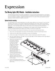
Basic <strong>Assembly</strong><br />
9<br />
10<br />
11<br />
12<br />
3<br />
4<br />
13<br />
7<br />
6<br />
5<br />
Reference Part<br />
Description Quantity<br />
Number Number<br />
Required<br />
1 7061A2001 Lamp socket assembly, black 1<br />
7061A2001-1 Lamp socket assembly, white 1<br />
2 7061A3006 Bracket, yoke, black 1<br />
7061A3006-1 Bracket, yoke, white 1<br />
3 HW5172 Bolt, hex, 1/4-20 x 1”, black zinc 2<br />
4 HW522 Washer, flat, 1/4, black zinc 2<br />
5 HW5125 Bolt, carriage, 5/16-18, black zinc 1<br />
6 HW5126 Washer, flat, 5/16, black zinc 1<br />
7 HW8144 Handle, yoke knob, 5/16-18 1<br />
8 7061A2015 Housing <strong>Assembly</strong>, EA, black 1<br />
7061A2015-1 Housing <strong>Assembly</strong>, EA, white 1<br />
9 7061A4002 Lens, clear, VNSP 1<br />
10 7061A4003 Lens, stipple, NSP 2<br />
11 7061A4005 Lens, medium flood, MFL 1<br />
12 7061A4006 Lens, wide flood, WFL 1<br />
13 7061A4029 Lens stop 1<br />
Basic <strong>Assembly</strong> 1<br />
LABEL LABEL<br />
DIRECTION DIRECTION<br />
2<br />
8<br />
4<br />
3<br />
1<br />
Figure 1
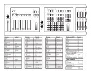
Lamp Socket <strong>Assembly</strong><br />
8<br />
4<br />
9<br />
2<br />
7<br />
WARNING! WARNING!<br />
Reference Part<br />
Description Quantity<br />
Number Number<br />
Required<br />
1 7060A3025 Screw, 1/4-20 x 1.55, knurled 1<br />
2 7060A4019 Label, Fixture Warning 1<br />
3 7061A3023 Burner, casting, black 1<br />
7061A3023-1 Burner, casting, white 1<br />
4 7061A3024 Strain relief, black 1<br />
7061A3024-1 Strain relief, white 1<br />
5 7061A4011 Focus handle, black 1<br />
7061A4011-1 Focus handle, white 1<br />
6 7061B7002 Ground Wire, 48” 1<br />
7 HW2182 Screw, 6-32 x 1/4, PhPh, Taptite, zinc 1<br />
8 HW3105 Screw, 8-32 x 1/2, PhPh, Taptite, SEMS 4<br />
9 M706 Complete TP 22 CLCM assembly 1<br />
10 W6195 Sleeve, fiberglass, 39”, black 1<br />
W689-1 Sleeve, fiberglass, 39”, white 1<br />
11 7060A4094 Label, 750W, handle, black 1<br />
7060A4095 Label, 750W, handle, white 1<br />
2 Source Four <strong>PAR</strong> <strong>Assembly</strong> <strong>Guide</strong><br />
11<br />
10<br />
6<br />
750<br />
3<br />
5<br />
1<br />
Figure 2
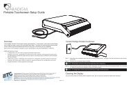
Assemble lamp socket<br />
TP22<br />
assembly (9)<br />
Knurled head<br />
screw hole<br />
Sleeving (10)<br />
Note:<br />
Ground wire (6)<br />
and 6-32 x 1/4<br />
screw (7)<br />
Strain relief<br />
casting (4,)<br />
Tighten 2<br />
Tighten 1 Tighten 3<br />
Burner casting<br />
(3)<br />
Tighten 4<br />
Figure 3<br />
Tools Required:<br />
• #2 Phillips screwdriver<br />
Step 1: Install the ground wire (6) and the TP22 assembly (9) in the sleeving (10). See<br />
Figure 3.<br />
Step 2: Snap the focus handle (5) onto the burner (3). See Figure 2.<br />
Step 3: Secure the ground wire lug (6) onto the burner casting (3) using screw (7).<br />
Step 4: Place the TP22 assembly (9) into the burner casting (3). See Figure 3.<br />
Position the wires with the green ground wire on top of the two TP22 white leads.<br />
Make sure the green ground wire is not touching any part of the burner casting.<br />
Step 5: Insert the screws (8) into the four positions in the strain relief casting (4). See<br />
Figure 3.<br />
Step 6: Position the sleeving assembly (10) as shown in Figure 3. Fold the sleeving so it<br />
fits cleanly in the slot between the burner and the strain relief.<br />
Step 7: Place the strain relief (4) on the burner casting (3). Loosely attach the screws (8).<br />
The TP22 assembly (9) must be centered in the strain relief opening (4). See<br />
Figure 3.<br />
Step 8: To guard against stripping the screws, tighten them in the order shown in<br />
Figure 3.<br />
Step 9: Make sure the focus handle is secure, then insert the knurled head screw (1)<br />
through the handle (5) into the burner casting (3). Tighten securely.<br />
Lamp Socket <strong>Assembly</strong> 3
Housing <strong>Assembly</strong><br />
6<br />
5<br />
13<br />
12<br />
5<br />
7 (2 placesboth<br />
sides)<br />
8<br />
9<br />
2<br />
Figure 4<br />
Reference Part<br />
Description Quantity<br />
Number Number<br />
Required<br />
1 7060A3100 Clip, gel retainer 1<br />
2 7061A3013 Spring clip, rotator 1<br />
3 7061A3014 Reflector, molded glass, coated, black 1<br />
7061A3014-1 Reflector, molded glass, coated, white 1<br />
4 7061A3025 Barrel, right, black 1<br />
7061A3025-1 Barrel, right, white 1<br />
5 7061A2019 Barrel, left, black 1<br />
7061A2019-1 Barrel, left, white 1<br />
6 7061A3029 Clip, rotator, pressure 1<br />
7 7061A4001 Pad, silicon, reflector mount 4<br />
8 7061A4012 Lens rotator, black 1<br />
7061A4012-1 Lens rotator, white 1<br />
9 7061A4029 Lens stop 1<br />
10 7061A4030 Label, <strong>ETC</strong> <strong>S4</strong> <strong>PAR</strong>, black 1<br />
7061A4030-1 Label, <strong>ETC</strong> <strong>S4</strong> <strong>PAR</strong>, white 1<br />
11 HW492 Screw, 10-32 x 5/8, PhPH, Taptite 3<br />
12 HW4145 Screw, 10-32 x 3/8, PhPH, Taptite, BO 1<br />
13 HW6128 Plug, focus knob, black 1<br />
HW6128-1 Plug, focus knob, white 1<br />
14 HW750 Spring, retainer 1<br />
4 Source Four <strong>PAR</strong> <strong>Assembly</strong> <strong>Guide</strong><br />
1<br />
14<br />
10<br />
3<br />
4<br />
11
Assemble housing<br />
WARNING:<br />
Tools Required:<br />
• Minimally padded work surface (cardboard, carpet, or rubber mat recommended)<br />
• Phillips screwdriver<br />
Step 1: Install the reflector mount silicon pads (7) in the left barrel assembly (6). Install<br />
the pads in two places on both sides. See Figure 4.<br />
Step 2: Install the lens stop (9) and rotator spring clip (2) into the lens rotator (8). Install<br />
the lens rotator into the left barrel (5).<br />
Step 3: Install the rotator pressure clip (6) into the left barrel (5) and attach using screw<br />
(12).<br />
Step 4: Install the gel retainer clip (1) and the spring retainer (14) into the right barrel (4).<br />
Step 5: Install the reflector (3) into the left barrel (5). Align the rib on the reflector with the<br />
left barrel pocket as shown in Figure 5.<br />
Step 6: Attach the right barrel (4) to the left barrel (5) using three screws (11). Hand<br />
tighten only (25 in. lbs.).<br />
Step 7: Clean reflector. See “Cleaning the reflector” on page 6.<br />
Step 8: Check for ease of movement of the gel clip retainer (1). The clip should latch into<br />
the left barrel in the down position and be free of binding.<br />
Step 9: Check for smooth rotation of the lens rotator (8).<br />
Step 10: Snap the focus knob plug (13) into the bottom of the fixture.<br />
Step 11: Attach label (10) onto the left barrel as shown in Figure 5.<br />
Align rotator spring clip (2) on rotator<br />
with rotator tab on left barrel (6)<br />
This procedure may crack or break the reflector. Always wear gloves, safety<br />
glasses, and a dust mask when performing this procedure.<br />
ALIGN ROTATOR CLIP<br />
ALIGN ZOOM LENS<br />
Align rib on reflector (8) with left barrel (6) pocket<br />
Left barrel alignment arrow<br />
Label (10) alignment<br />
TE C Source Four <strong>PAR</strong><br />
Figure 5<br />
Housing <strong>Assembly</strong> 5
Step 12: Hold the lens by the edge and position it so the wave side faces the rear of the<br />
fixture. See Figure 6.<br />
Step 13: From the top of the fixture, slide the lens behind the lens catchers and position it<br />
behind the tabs on the bottom of the lens rotator ring.<br />
Step 14: Gently push the top of the lens inward until it snaps behind the spring clip.<br />
Spring clip<br />
Tab<br />
Retaining clip<br />
Step 15: Install the lamp socket assembly (See “Assemble lamp socket” on page 3.) to the<br />
barrel housing assembly and secure with brass knurled screw on rear of lamp<br />
socket assembly.<br />
Cleaning the reflector<br />
WARNING:<br />
Step 1: Remove the lens to expose the reflector so you can access it from the front of the<br />
luminaire.<br />
Step 2: Remove dust with a blast of oil-free air or wipe with a clean, lint-free cloth.<br />
Isopropyl alcohol, distilled water or a 50%-50% mixture of each can be used to<br />
clean the glass surface.<br />
Step 3: Reinstall a lens before using the luminaire.<br />
Cleaning the lens<br />
WARNING:<br />
Lens Catcher<br />
Retaining clip<br />
Spring clip<br />
Figure 6<br />
Do not use ammonia-based or other harsh commercial cleaners. Clean<br />
reflector only as directed.<br />
Commercially available glass cleaning agents should be avoided as they<br />
may contain ammonia, other harsh chemical detergents or abrasive agents.<br />
These cleaners may damage the glass surface and the Anti-Reflective<br />
coatings. Do not immerse or soak the glass in any cleaning solution.<br />
Do not use ammonia-based or other harsh commercial cleaners. Clean lens<br />
only as directed.<br />
Commercially available glass cleaning agents should be avoided as they<br />
may contain ammonia, other harsh chemical detergents or abrasive agents.<br />
These cleaners may damage the glass surface and the Anti-Reflective<br />
coatings. Do not immerse or soak the glass in any cleaning solution.<br />
Remove dust with a blast of oil-free air or wipe with a clean, lint-free cloth. Isopropyl alcohol,<br />
distilled water or a 50%-50% mixture of each can be used to clean the glass surface.<br />
6 Source Four <strong>PAR</strong> <strong>Assembly</strong> <strong>Guide</strong>
Lens identification<br />
Lenses for the Source Four<strong>PAR</strong> come in four varieties. The type or beam spread can be<br />
identified by the texture of the lens.<br />
VNSP<br />
NSP<br />
XWFL (Optional)<br />
Very narrow spot<br />
Clear glass<br />
15° Round beam shape<br />
MFL WFL<br />
Medium flood<br />
Fewer facets, sized 6 x 22mm<br />
21° x 34° Oblong beam shape<br />
Narrow spot<br />
Stipple glass (slight diffuse texture)<br />
19° Round beam shape<br />
Wide flood<br />
Many facets, sized 6 x 12mm<br />
30° x 51° Oblong beam shape<br />
Extra-wide, or buxom, lens<br />
Molded, borosilicate lens, multi-faceted<br />
60° Round beam shape<br />
Figure 7<br />
Housing <strong>Assembly</strong> 7
8 Source Four <strong>PAR</strong> <strong>Assembly</strong> <strong>Guide</strong>
Housing <strong>Assembly</strong> 9
Corporate Headquarters � 3031 Pleasant View Road, P.O. Box 620979, Middleton, Wisconsin 53562-0979 USA � Tel +608 831 4116 � Fax +608 836 1736<br />
London, UK � Unit 26-28, Victoria Industrial Estate, Victoria Road, London W3 6UU, UK � Tel +44 (0)20 8896 1000 � Fax +44 (0)20 8896 2000<br />
Rome, IT � Via Ennio Quirino Visconti, 11, 00193 Rome, Italy � Tel +39 (06) 32 111 683 � Fax +39 (06) 32 656 990<br />
Holzkirchen, DE � Ohmstrasse 3, 83607 Holzkirchen, Germany � Tel +49 (80 24) 47 00-0 � Fax +49 (80 24) 47 00-3 00<br />
Hong Kong � Rm 1801, 18/F, Tower 1 Phase 1, Enterprise Square, 9 Sheung Yuet Road, Kowloon Bay, Kowloon, Hong Kong � Tel +852 2799 1220 � Fax +852 2799 9325<br />
Service: (Americas) service@etcconnect.com � (UK) service@etceurope.com � (DE) techserv-hoki@etcconnect.com � (Asia) service@etcasia.com<br />
Web: www.etcconnect.com � Copyright © 2007 <strong>ETC</strong>. All Rights Reserved. � Product information and specifications subject to change.<br />
7061M2500-06.01 � Rev A � Released 08/2007