EIB Interface.QXD - Somfy
EIB Interface.QXD - Somfy
EIB Interface.QXD - Somfy

Create successful ePaper yourself
Turn your PDF publications into a flip-book with our unique Google optimized e-Paper software.
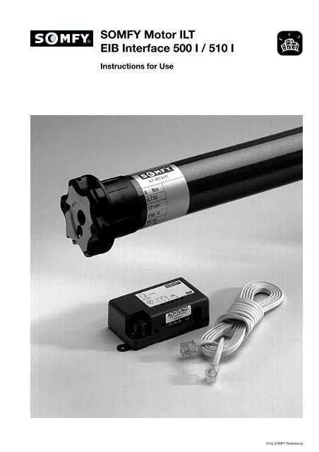
SOMFY Motor ILT<br />
<strong>EIB</strong> <strong>Interface</strong> 500 I / 510 I<br />
Instructions for Use<br />
© by SOMFY Rottenburg
SOMFY Motor ILT<br />
<strong>EIB</strong> <strong>Interface</strong> 500 I / 510 I<br />
Instructions for Use<br />
Dear Customer,<br />
Thank you for the trust you have vested in our products.<br />
With your purchase of this SOMFY Motor ILT you have<br />
acquired a product of highest quality made and equipped<br />
with state of the art technology.<br />
Before installing this product, please read these<br />
instructions thoroughly and observe all safety warnings<br />
that have been highlighted with the following symbols:<br />
Warning:<br />
High Voltage!<br />
Important Instructions<br />
Damage caused by non-observance of the safety and<br />
installation instructions in this manual or negligence are<br />
not covered by the warranty. SOMFY cannot and will not<br />
assume any liability for consequential damage or losses<br />
caused by negligence or non-observance of these<br />
installation instruction or local electrical and <strong>EIB</strong><br />
regulations and guidelines!<br />
Should you have any questions or problems with<br />
installing our product, call our technical support hotline:<br />
+49 180 52 52 131. Our support engineers will do their<br />
best to provide you with the support you need.<br />
Once again we would like to thank you for your trust in<br />
SOMFY products.<br />
SOMFY Feinmechanik und Elektrotechnik GmbH<br />
Felix-Wankel-Straße 50<br />
72108 Rottenburg/Neckar<br />
Table of Contents<br />
Advantages and Description of SOMFY Motor ILT ...................................................................................... 3<br />
1. Shaft Pre-Assembly .................................................................................................................................... 3<br />
1.1 Riveting the dog ................................................................................................................................ 4<br />
1.2 Drive types ........................................................................................................................................ 4<br />
2. Adjustment Instructions for SOMFY Motor ILT ........................................................................................ 4<br />
2.1 Final position adjustment with control box ...................................................................................... 4<br />
2.2 Upper final position adjustment ........................................................................................................ 4<br />
2.2.1 Change of direction .......................................................................................................................... 5<br />
2.3 Lower final position adjustment ........................................................................................................ 5<br />
2.4 User setting ...................................................................................................................................... 5<br />
2.4.1 Programming user setting with control box ...................................................................................... 5<br />
2.4.2 Initiating user setting ........................................................................................................................ 5<br />
3. Western Connector Pin Assignment and Attachment ............................................................................ 5<br />
3.1 Control line pin assignment (plan view) ............................................................................................ 5<br />
3.2 Attaching western connectors .......................................................................................................... 5<br />
4. Safety Systems ............................................................................................................................................ 6<br />
4.1 Trip-free dog .................................................................................................................................... 6<br />
4.2 Anti-intrusion system ........................................................................................................................ 7<br />
5. Technical Data ............................................................................................................................................ 8<br />
6. <strong>EIB</strong>-<strong>Interface</strong> 500 I/510 I ............................................................................................................................ 9<br />
6.1 Safety ................................................................................................................................................ 9<br />
6.2 Description ........................................................................................................................................ 9<br />
6.3 Installation ........................................................................................................................................ 9<br />
6.4 Connection ........................................................................................................................................ 9<br />
6.5 Commissioning ................................................................................................................................ 10<br />
6.6 Technical data / terminal connection plan ........................................................................................ 16<br />
2<br />
© by SOMFY Rottenburg
425<br />
SOMFY Motor ILT<br />
Instructions for Use<br />
Advantages of<br />
SOMFY Motor ILT:<br />
Final position adjustment<br />
The SOMFY Motor ILT is adjusted electronically through<br />
an extra-low voltage control line. It is not necessary to<br />
manually adjust the drive.<br />
==> Any necessary adjustments caused e. g. by a<br />
lengthening or shortening of the roller shutter can be<br />
made without opening the roller shutter box.<br />
Repeat accuracy of final positions<br />
==> SOMFY Motors are furnished with an exceptionally<br />
high degree of repeat accuracy (± 2 %).<br />
Final position recognition<br />
The electronic final position recognition does not<br />
mechanically stress the support material.<br />
==> Protects and prolongs the serviceable life of the roller<br />
shutter.<br />
Description of<br />
SOMFY Motor ILT<br />
SOMFY Motors are composed of single-phase capacitor<br />
motors, brakes, gears and an electromechanical final<br />
position shutoff system.<br />
Important information that requires your<br />
attention before installing the SOMFY Motor:<br />
CE conformity and interference suppression<br />
SOMFY Motors conform with the following European<br />
guidelines: 73/23/EEC and 89/336/EEC.<br />
SOMFY Motors in damp environments<br />
SOMFY drives are weather-proof protected in<br />
accordance with EN 60529. Observe VDE regulations, e.<br />
g. 0100, Sections 701, 702 and 737 as well as obligatory<br />
regulations and guidelines issued by local power<br />
suppliers and inspection authorities.<br />
Immobilisation detection<br />
SOMFY Motors are equipped with an integrated<br />
immobilization detection system that monitors the<br />
upwards movements of the roller shutters. The drive<br />
stops immediately.<br />
==> Protects the support material, e. g. when roller<br />
shutters are blocked by ice.<br />
1. Shaft Pre-Assembly<br />
Prefabricated spindles<br />
Slide the drive together with the suitable spindle adapter<br />
(1) and dog (2) into the spindle.<br />
Precision tubes<br />
Obstacle detection in conjunction with a trip-free dog<br />
(accessory)<br />
The obstacle detection system monitors the downward<br />
movement of the roller shutter and recognises a blocked<br />
shutter.<br />
==> The drive stops immediately and automatically<br />
provides clearance for the removal of the obstacle.<br />
1<br />
Unlatch the spindle on the drive end. Slide drive into the<br />
spindle so that the adapter cam fits into the jog.<br />
2<br />
Warning! Slide drive into the spindle. Never<br />
use a hammer or force of any kind!<br />
1.1 Riveting dog to precision tube<br />
3<br />
© by SOMFY Rottenburg
SOMFY Motor ILT<br />
Instructions for Use<br />
spindles<br />
● Adjust distance between dog and drive pursuant to L 2<br />
(see table under 1.2) and rivet or screw dog with 4<br />
rivets or screws.<br />
Self-tapping screws: 4 screws (5 x 10 mm)<br />
Blind rivets: 4 steel rivets (ÿ 5 mm steel)<br />
1.2 Drive types<br />
L 1<br />
L 2<br />
L 3<br />
Drive type L 1 L 2 L 3<br />
ILT Jet 8/17 613 590 605<br />
ILT Ceres 10/17 613 590 605<br />
ILT Atlas 15/17 613 590 605<br />
ILT Meteor 20/17 663 640 655<br />
ILT Apollo 30/17 663 640 655<br />
ILT Mariner 40/17 753 730 745<br />
2.1 Final position adjustment with control box<br />
● Ensure that the drive is properly and duly connected to<br />
a 230 VAC mains supply.<br />
Important:<br />
1. The installation, testing and<br />
commissioning of 230 V installations must be<br />
carried out by qualified electricians or<br />
electrical technicians. Observe ISO<br />
standards, especially DIN-VDE standards,<br />
and ensure that the electrician/electrical<br />
technician has received the installation<br />
instructions for each drive.<br />
2. Before activating the 230 VAC power<br />
supply, plug in and screw down the connector<br />
to the drive.<br />
● Connect the western connector on one end of the<br />
Programming buttons<br />
B C D<br />
A<br />
2. Adjustment Instructions for<br />
SOMFY Motor ILT<br />
Use the control box to adjust the final positions of the<br />
motors. Manual adjustment is not necessary.<br />
Each motor comes equipped with two brought out lines: a<br />
3-conductor cable for supply voltage and a 4-conductor<br />
control line.<br />
RJ 9<br />
connector<br />
LED<br />
control line to the control box.<br />
When control line and control box are properly connected<br />
and the power supply has been activated the red LED on<br />
the control box flashes quickly.<br />
2.2 Upper final position adjustment<br />
● Each motor comes equipped with two brought out lines: a<br />
3-cond<br />
● Raise roller shutter with the UP button (B) to the<br />
desired position.<br />
● When upper final position is reached, release the<br />
UP button (B).<br />
conductor<br />
control line<br />
SELV = 5 V<br />
power supply ~230 V<br />
earth = gr/ye<br />
phase = br<br />
neutral = bl<br />
Important:<br />
Do not raise shutter to<br />
mechanical limit.<br />
2-3 cm clearance is<br />
required!<br />
4<br />
© by SOMFY Rottenburg
SOMFY Motor ILT<br />
Instructions for Use<br />
2.2.1 Change of direction<br />
Should the roller shutter not move in the desired<br />
direction, e. g. upwards after pressing the UP button,<br />
press and hold the STOP button for approximately 2<br />
seconds.<br />
2.3 Lower final position<br />
adjustment<br />
● Set slide switch (A) to the<br />
position for adjusting the lower<br />
final position.<br />
● Lower roller shutter with the<br />
DOWN button (D) to the desired<br />
position.<br />
● When lower final position is reached, release the<br />
DOWN button (D).<br />
Important:<br />
It is possible to correct final position settings<br />
by simply repeating the above procedures.<br />
2.4 User setting (intermediate position)<br />
The user setting has now been saved.<br />
2.4.2 Initiating user setting<br />
The user setting can be initiated when the roller shutter is<br />
stopped in any position by pressing the STOP button (C).<br />
3. Western Connector Pin<br />
UP (red)<br />
PE (blue)<br />
+5 V DC (white)<br />
DOWN (yellow)<br />
Assignment and Attachment<br />
3.1 Control line pin assignment (plan view)<br />
Depending on the cable type the conductors may also be<br />
colour-coded as follows: black, red, green, yellow.<br />
3.2 Attaching western connectors<br />
Use a pair of crimping pliers to strip and shorten a control<br />
The Motor allows you to program the roller shutter with a<br />
user setting. This means that in addition to the upper and<br />
lower final positions you have a user-programmable<br />
intermediate position where the roller shutter<br />
automatically stops when you press the STOP button and<br />
the drive is not running.<br />
2.4.1 Programming user setting with control box<br />
Set slide switch (A) on the control box to the middle<br />
position. Your control box now functions like a standard<br />
remote control.<br />
Press the DOWN button (D) and the roller shutter travels<br />
to the lower final position and automatically stops.<br />
red<br />
blue<br />
white<br />
yellow<br />
colour marking<br />
control line cable<br />
red<br />
blue<br />
white<br />
yellow<br />
Press the UP button (B) and the roller shutter travels to<br />
the upper final position and automatically stops.<br />
To stop the roller shutter simply press the STOP button<br />
(C).<br />
● Stop the roller shutter at the desired user setting<br />
position.<br />
● When the roller shutter has fully stopped at that<br />
position, press and hold the STOP button (C) for 5<br />
seconds.<br />
line cable and to attach a western connector.<br />
Important:<br />
Ensure that the western connectors are mounted<br />
inversely to each other. Otherwise the pin assignment<br />
of the connectors will no<br />
longer correspond properly (use colour marking on<br />
the control line for orientation).<br />
5<br />
© by SOMFY Rottenburg
SOMFY Motor ILT<br />
Instructions for Use<br />
4. Safety Systems<br />
„Right“ trip-free dog<br />
4.1 Trip-free dog<br />
The SOMFY Motor ILT together with the SOMFY trip-free<br />
dog is equipped with an obstacle recognition system. If<br />
the roller shutter run into an obstacle, the drive stops<br />
automatically and clearance is provided to remove the<br />
obstacle.<br />
Depending on the structure of the support material,<br />
observe that a „right“ or „left“ version of the trip-free dog<br />
is required.<br />
„Left“ trip-free dog<br />
Please note:<br />
Trip-free dogs and the anti-intrusion system can only be<br />
used together with an <strong>EIB</strong> <strong>Interface</strong> 510 I in a roller shutter<br />
system.<br />
LT 50 trip-free dog (reinforced) List No.<br />
Left trip-free dog 9706003<br />
Right trip-free gog 9706004<br />
6<br />
© by SOMFY Rottenburg
SOMFY Motor ILT<br />
Instructions for Use<br />
4.2 Anti-intrusion system<br />
The electromagnetic brake integrated in each SOMFY<br />
Motor ILT prevents the shutter spindle from rotating when<br />
an attempt is made to manually push up the roller shutter.<br />
The anti-intrusion system applies a downward force on<br />
the roller shutter. The shutter can no longer be moved<br />
and wound around the spindle by hand. The SOMFY<br />
Motor ILT and the SOMFY anti-intrusion system form an<br />
effective safety package.<br />
Bolt<br />
List No.<br />
Two-membered bolt; distance a: 80-130 mm<br />
Exemplary application:<br />
standard profiles in porch element 9700209<br />
Three-membered bolt; distance a: 120-170 mm<br />
Exemplary application:<br />
standard profiles in porch element<br />
and 24 and 30 slat prefabricated boxes. 9700210<br />
Four-membered bolt; distance a: 160-210 mm<br />
Exemplary application:<br />
stand.-profiles in 30 and 36 cm prefabricated boxes 9700211<br />
Two-membered for mini-profiles;<br />
distance a: 80-130 mm. Exemplary application:<br />
Mini-profile in porch element 9700212<br />
Three-membered for mini-profiles;<br />
Abstand a: 120-170 mm. Exemplary application:<br />
Mini-profile in porch element 9700213<br />
The choice of a suitable locking bolt is dependent upon<br />
the roller shutter system in use. The distance (a) between<br />
the spindle centre and the first shutter slat is decisive.<br />
The first shutter slat should still be in the runners when<br />
the roller shutter is in the lower final position.<br />
a<br />
Locking rings<br />
List No.<br />
for 60 wrench<br />
Exemplary application:<br />
octagonal spindle 9700215<br />
(Two locking rings required per locking bolt.)<br />
Please note:<br />
Trip-free dogs and the anti-intrusion system can only be<br />
used together with an <strong>EIB</strong> <strong>Interface</strong> 510 I in a roller shutter<br />
system. By integrating the anti-intrusion system to an<br />
existing roller shutter unit the slat roll diameter increases.<br />
7<br />
© by SOMFY Rottenburg
SOMFY Motor ILT<br />
Instructions for Use<br />
5. Technical Data<br />
ILT Jet<br />
8/17<br />
ILT Ceres<br />
10/17<br />
ILT Atlas<br />
15/17<br />
ILT Meteor<br />
20/17<br />
ILT Apollo<br />
30/17<br />
ILT Mariner<br />
40/17<br />
Safety class<br />
IP protection classification<br />
Rated torque<br />
Rated rotational speed<br />
Rated voltage<br />
Rated output<br />
Current consumption<br />
Frequency<br />
Rated consumption<br />
Pick-up time<br />
Ultimate interruption<br />
capacity<br />
Base adapter<br />
for 50 mm spindle<br />
Duty type as per VDE 0530<br />
Product standard<br />
Conformity<br />
II<br />
IP 44<br />
8 Nm 10 Nm 15 Nm 20 Nm 30 Nm 40 Nm<br />
17 rpm<br />
~230 VAC (207 V – 244 V)<br />
90 W 120 W 140 W 160 W 240 W 270 W<br />
0,45 A 0,5 A 0,65 A 0,75 A 1,1 A 1,2 A<br />
50 Hz<br />
90 W 120 W 140 W 160 W 240 W 270 W<br />
4 min.<br />
300 rotations<br />
50 x 1.5 mm<br />
intermittent operation tr = 40% / make-up time tB = 4 min.<br />
VDE 0700 Section 238<br />
CE pursuant to EN 50081-1 und EN 50082-1<br />
Control line<br />
Control line type AWG26 (4 x 0.12 mm 2 )<br />
Connector type western connector Typ RJ9 4/4<br />
Length between drive<br />
and control box<br />
10 m max.<br />
8<br />
© by SOMFY Rottenburg
<strong>EIB</strong>-<strong>Interface</strong> 500 I/510 I<br />
Instructions for Use<br />
6. <strong>EIB</strong>-<strong>Interface</strong> 500 I/510 I<br />
6.1 Safety<br />
The installation, testing and commissioning of<br />
<strong>EIB</strong>s and <strong>EIB</strong> bus devices must be carried out<br />
by qualified electricians or electrical<br />
technicians. Observe ISO standards,<br />
especially DIN-VDE standards, as well as the<br />
installation instructions in the ZVEI/ZVEH*<br />
<strong>EIB</strong>-Manual when laying and connecting<br />
leads and cables for bus and peripheral<br />
devices.<br />
6.3 Installation<br />
Before installing the <strong>EIB</strong> interface and the<br />
Motor, ensure that the drive’s 230 VAC mains<br />
connection cable is disconnected from the <strong>EIB</strong><br />
interface terminals.<br />
The <strong>EIB</strong> interface can be surface or flush-mounted.<br />
Flush-mounting<br />
We recommend the use of a flush mounting box 107 x<br />
107 x 57 mm (e. g. Kaiser). Remove the mounting eyelets<br />
(1) and insert the <strong>EIB</strong> interface into the flush-mounting<br />
box.<br />
6.2 Description<br />
IP 20<br />
5V / 29V<br />
1 2 3 4 5<br />
6.4 Connection<br />
1 mounting eyelet 4 programming LED<br />
2 <strong>EIB</strong> bus terminal 5 programming button<br />
3a terminals 1-5, 6 terminal for control line<br />
connection-side<br />
Motor<br />
3b terminals 1-5,<br />
(western socket)<br />
screw-clamp-side<br />
Set terminals 1-5 (3) only potential-free!<br />
Pin assignment:<br />
• bus terminal (2): bus cable conductors<br />
• terminals (3) 1-3: conventional switch (page 7)<br />
• terminals (3) 4+5: window contact<br />
• western socket (6): Motor control line<br />
9<br />
© by SOMFY Rottenburg
<strong>EIB</strong>-<strong>Interface</strong> 500 I/510 I<br />
Instructions for Use<br />
6.5 Commissioning<br />
Operate <strong>EIB</strong> interface in accordance<br />
with the specific technical data!<br />
To program the physical address, press the programming<br />
button (5). Programming LED (4) illuminates.<br />
Recommendation: Use a screwdriver (see illustration) to<br />
access the programming button (5).<br />
Prior to commissioning your <strong>EIB</strong> interface, program the<br />
physical address, group address, parameters and user<br />
application in the ETS. You will find the necessary <strong>EIB</strong><br />
actuator product data in the product data base in the<br />
product family directory „roller shutters“ and the product<br />
type „Motor“.<br />
The <strong>EIB</strong> interface is programmed through the ETS while<br />
commissioning by simply applying bus voltage to the<br />
system. 230V operating voltage is not necessary for<br />
programming.<br />
<strong>EIB</strong> <strong>Interface</strong> 500 I Communication Objects<br />
No. Name Function Description<br />
0 roller shutter position show 0 - 100 % Indicates actual roller shutter position. The shutter<br />
position can either be communicated to the bus<br />
periodically or when the shutter stops after moving.<br />
1 obstacle recognition UP show YES / NO Indicates an obstacle (e. g. frozen shutter) while the<br />
roller shutter is moving upwards (together with a SOMFY<br />
trip-free). An obstacle triggers the transmission of „1“,<br />
the signal can be displayed through a suitable actuator<br />
(display, binary output).<br />
2 obstacle recognition show YES / NO Indicates an obstacle while the roller shutter is moving<br />
DOWN<br />
downwards (together with a SOMFY trip-free).<br />
An obstacle triggers the transmission of „1“.<br />
3 window contact status show open / closed Indicates the actual status of the window contact. If the<br />
window parameter „window contact (external/local)“ is<br />
set to „local“, all Motor movements can be stopped via a<br />
local window contact. If the window is open, a „1“ is<br />
transmitted and the Motor is automatically disabled. If<br />
the window is closed, a „0“ is transmitted and the Motor<br />
is re-enabled.<br />
4 move command UP / DOWN A message to this object causes the drive to actuate.<br />
„0“ = upper final position, „1“ = lower final position.<br />
5 STOP command STOP A message to this object causes the drive to stop.<br />
10<br />
© by SOMFY Rottenburg
<strong>EIB</strong>-<strong>Interface</strong> 500 I/510 I<br />
Instructions for Use<br />
Nr. Name Function Description<br />
6 inhibit move commands YES / NO If the window parameter „window contact<br />
(external/local)“ is set to „external“, all Motor<br />
movements can be stopped via a local window contact.<br />
A „1“ stops the Motor automatically, a „0“ re-enables<br />
the Motor.<br />
7 safety priority command A „1“ generates a move command to the programmable<br />
safety position (upper or lower final position). The<br />
system is deactivated until a „0“ re-enables the system.<br />
If the parameter „receive safety signal (static/cyclic)“ is<br />
set to „cyclic“, the system can only operate if a „0“ is<br />
received periodically. If the required „0“ is not received<br />
within the specific period of time, the drive automatically<br />
move to the safety position.<br />
8 user setting move / save Drive moves to programmed user setting OR saves the<br />
actual position as the user setting when the system<br />
receives a message from this object. The value in the<br />
received message is not important. The actual value of<br />
object no. 9 (ìuser setting modeî) determines which<br />
function is performed.<br />
9 user setting mode save ON / OFF Selection of function for object no. 8. A moving<br />
command (i.e. object value = „0“) moves the drive to<br />
user setting if object no. 8 is engaged. If the save mode<br />
is enabled (i.e. object value = „1“), the drive saves the<br />
actual roller shutter position as the new user setting, if<br />
object no. 8 is engaged.<br />
10 sunshade position move Drive moves to programmed sun position if a „1“ is<br />
received and the roller shutter is above the sun position.<br />
The sun position is set during initial installation. A „0“<br />
moves the drive either to the upper final position or the<br />
drive ignores the command.<br />
11<br />
© by SOMFY Rottenburg
<strong>EIB</strong>-<strong>Interface</strong> 500 I/510 I<br />
Instructions for Use<br />
<strong>EIB</strong> <strong>Interface</strong> 500 I Parameter Descriptions<br />
(Factory settings are in italics!)<br />
Parameter Settings Description<br />
❐ Safety<br />
safety position upper final position Drive moves to upper final position.<br />
lower final position Drive moves to lower final position<br />
receive safety message static Drive moves to programmed safety position when noncyclically<br />
transmitted safety message is not received.<br />
cyclic<br />
Drive moves to programmed safety position when<br />
cyclically transmitted safety message is received.<br />
safety monitor cycles 14 Monitoring period for receiving cyclic safety message.<br />
in 5 sec. [1..63]<br />
The monitoring time must be greater than the cyclic<br />
period of the transmitting element.<br />
❐ Window contact<br />
window contact external Drive disabled through message to Object no. 8.<br />
local<br />
Locally connected window contact disables drive.<br />
window contact NO contact Disenabled by opening contact.<br />
NO contact<br />
Disenabled by closing contact.<br />
window contact: transmit value YES The actual window status indicated through object<br />
no. 3.<br />
NO<br />
Window status not indicated.<br />
❐ Roller shutter<br />
send roller shutter position YES Actual roller shutter position is transmitted<br />
(0% - 100%).<br />
NO<br />
Roller shutter position is not transmitted.<br />
send periodically YES Roller shutter position updated every second.<br />
NO<br />
Roller shutter position updated when drive stops.<br />
❐ Sunshade position<br />
sun position (0% - 100%) 80% A „1“ moves the drive to the programmed sun position.<br />
open YES A „0“ move the drive from the programmed sun<br />
position to the upper final position.<br />
NO<br />
The drive remains in the sun position.<br />
❐ Obstacle recognition<br />
alarm YES Alarm signal issued if an upward movement obstacle<br />
upward movement obstacle<br />
is detected.<br />
NO<br />
No alarm signal if an upward movement obstacle<br />
is detected.<br />
alarm YES Alarm signal issued if a downward movement obstacle<br />
downward movement obstacle<br />
is detected.<br />
NO<br />
No alarm signal if a downward movement obstacle is<br />
detected.<br />
12<br />
© by SOMFY Rottenburg
<strong>EIB</strong>-<strong>Interface</strong> 500 I/510 I<br />
Instructions for Use<br />
<strong>EIB</strong> <strong>Interface</strong> 510 I Communication Objects<br />
No. Name Function Description<br />
0 roller shutter position show 0% - 100% Indication of actual roller shutter position in %. The<br />
position can be communicated to the bus periodically or<br />
only after the roller shutter has come to a complete stop.<br />
1 lower final position show YES / NO Indication of lower final position. When the drive reaches<br />
the lower final position, a „1“ is transmitted. When the<br />
drive leaves that position, a „0“ is transmitted.<br />
2 upper final position show YES / NO Indication of upper final position. When the drive<br />
reaches the upper final position, a „1“ is transmitted.<br />
When the drive leaves that position, a „0“ is transmitted.<br />
3 window contact status show open / closed Indicates the actual status of the window contact. If the<br />
window parameter „window contact (external/local)“ is<br />
set to „local“, all Motor movements can be stopped via a<br />
local window contact. A „1“ commands the Motor to<br />
automatically move to the disabled position (upper or<br />
lower final position, STOP or no move command).<br />
Further drive commands are ignored. A „0“ re-enables<br />
the Motor system.<br />
4 obstacle recognition show YES / NO Indicates an obstacle (e. g. frozen shutter) while the<br />
roller shutter is moving upwards or downwards (together<br />
with a SOMFY trip-free). An obstacle triggers the<br />
transmission of „1“ and disables the drive. A „0“ reenables<br />
the drive.<br />
5 alarm show YES / NO If the closed roller shutter is opened without a moving<br />
command (e. g. intrusion), a „1“ is transmitted. The<br />
alarm signal is reset with „0“. The alarm signal is only<br />
active at 85% - 100%.<br />
13<br />
© by SOMFY Rottenburg
<strong>EIB</strong>-<strong>Interface</strong> 500 I/510 I<br />
Instructions for Use<br />
No. Name Function Description<br />
6 move command UP / DOWN A „0“ message commands the drive to move to the<br />
upper final position, a „1“ message to the lower final<br />
position.<br />
7 STOP command STOP A message to this object causes the drive to stop.<br />
8 disable move command YES / NO If the window parameter „window contact<br />
(external/local)“ is set to „external“, all Motor<br />
movements can be stopped through this object. A „1“<br />
commands the Motor to automatically move to the<br />
disabled position (upper or lower final position, STOP or<br />
no move command). Further drive commands are<br />
ignored. A „0“ re-enables the Motor system.<br />
9 safety priority command A „1“ generates a move command to the programmable<br />
safety position (upper or lower final position). The Motor<br />
system is deactivated until a „0“ re-enables the system.<br />
10 move roller shutter move 0-100% The roller shutter can be moved to any position with<br />
position a 1 byte message (0% - 100%).<br />
<strong>EIB</strong> <strong>Interface</strong> 510 I Parameter Description<br />
(Factory settings are in italics)<br />
Parameter Settings Description<br />
❐ Safety<br />
safety position upper final position The drive moves to the upper final position.<br />
lower final position The drive moves to the lower final position.<br />
STOP<br />
The drive stops.<br />
no move command The drive moves up or down when this command is<br />
issued. Any further commands are blocked.<br />
receive safety signal static The drive moves to the programmed safety position if a<br />
non-cyclic safety message is received.<br />
cyclic<br />
The drive moves to the programmed safety position if a<br />
cyclic safety message is received.<br />
safety monitoring cycle 14 Überwachungszeitraum zum Empfang eines zyklischen<br />
in 5 seconds [1..63]<br />
Sicherheitstelegrammes. Die Überwachungszeit muß<br />
größer eingestellt werden, als die Zykluszeit des<br />
sendenden Teilnehmers.<br />
14<br />
© by SOMFY Rottenburg
<strong>EIB</strong>-<strong>Interface</strong> 500 I/510 I<br />
Instructions for Use<br />
Parameter Setting Description<br />
❐ Window contact<br />
window contact extern Drive is disabled with a message to object no. 8. The<br />
locally connected window contact disables the drive.<br />
local<br />
Opening the contact disables the drive.<br />
window contact NC contact Opening the contact disables the drive.<br />
NO contact<br />
Closing the contact disables the drive.<br />
window contact: send value YES The actual window contact status is indicated<br />
through object no. 3<br />
NO<br />
The actual window contact status is not<br />
indicated.<br />
blocking position upper final position The drive moves to the upper final position.<br />
lower final position The drive moves to the lower final position.<br />
STOP<br />
The drive stops.<br />
no move command The drive moves up or down when this<br />
command is issued. Any further commands<br />
are blocked.<br />
❐ Roller shutter<br />
send roller shutter position YES The actual roller shutter position is transmitted<br />
(0% - 100%).<br />
NO<br />
The roller shutter position is not transmitted.<br />
send periodically YES The updated roller shutter position is transmitted<br />
every second.<br />
NO<br />
The roller shutter position is transmitted after<br />
drive has come to a complete stop.<br />
❐ Sunshade position<br />
alarm YES Alarm signal is issued if an upward/downward<br />
movement obstacle is detected.<br />
NO<br />
No obstacle alarm signal is issued.<br />
15<br />
© by SOMFY Rottenburg
SOMFY Motor ILT<br />
<strong>EIB</strong>-<strong>Interface</strong> 500 I/510 I<br />
Instructions for Use<br />
6.6 Technical data / terminal connection plan<br />
<strong>EIB</strong>-<strong>Interface</strong> 500 I List No.: 1860020<br />
<strong>EIB</strong>-<strong>Interface</strong> 510 I List No.: 1860021<br />
Dimensions<br />
85 x 45 x 26 mm<br />
<strong>EIB</strong> bus current<br />
consumption<br />
< 10 mA DC<br />
IP rating IP 20<br />
Ambient conditions clean environment<br />
Operating temp. range 0° – +45°C<br />
Storage temperature -20 – +70°C<br />
range<br />
max. line length for conventional<br />
manipulator<br />
10 m<br />
max. drive length for window<br />
contact<br />
10 m<br />
max. line length for window<br />
contact<br />
10 m<br />
recommended cable type<br />
for control line I-Y(St)Y 2 x 2 x 0.8<br />
recommended cable type<br />
for control line of drive AWG 26 (4 x 0.12 mm 2 )<br />
Compliance with EMC- guidelines in accordance<br />
guidelines<br />
with <strong>EIB</strong> Manual Version<br />
2.21<br />
-conformity EN 60730<br />
DIN EN 50081-1<br />
(emitted interference)<br />
DIN EN 50082-1<br />
( interference immunity)<br />
terminal connection plan<br />
RJ 9 connector<br />
<strong>EIB</strong><br />
mains<br />
230 VAC<br />
1 2 3 4 5<br />
local<br />
manipulator<br />
3 x 0.75<br />
window contact<br />
Antrieb<br />
control line 4 x 0.12<br />
Parallel connection of one to three drives<br />
using western connector/western connector adapter<br />
mains 230 VAC mains 230 VAC mains 230 VAC<br />
western connector<br />
control line 4 x 0.12<br />
1 2 3 4 5<br />
<strong>EIB</strong><br />
window contact<br />
local<br />
manipulator<br />
All rights reserved to alter specifications without prior notice SOMFY SAS, capital 20.000.000 euros, RCS Bonneville<br />
303.970.230 © SOMFY / COM ref COM020229<br />
In Germany:<br />
Feinmechanik und Elektrotechnik GmbH<br />
Felix-Wankel-Straße 50 . D-72108 Rottenburg/Neckar<br />
Postfach 186 . D-72103 Rottenburg/Neckar<br />
Telefon (0 74 72) 930-0 . Telefax (0 74 72) 930-9<br />
Internet: http://www.somfy.de<br />
In Austria:<br />
SOMFY Feinmechanik und Elektrotechnik GmbH<br />
Johann-Herbst-Straße 23 . A-5061 Elsbethen-Glasenbach<br />
Telefon ++43 (0)662 62 53 08 . Telefax ++43 (0)662 62 53 08 22<br />
Internet: http://www.somfy.at