Model Npower 30kVA - 130kVA - United Power & Battery
Model Npower 30kVA - 130kVA - United Power & Battery
Model Npower 30kVA - 130kVA - United Power & Battery

Create successful ePaper yourself
Turn your PDF publications into a flip-book with our unique Google optimized e-Paper software.
®<br />
Liebert<br />
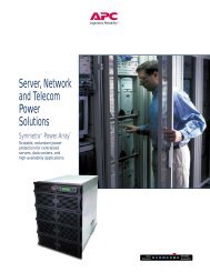
<strong>Npower</strong> <br />
30 to 130 kVA<br />
P o w e r A v a i l a b i l i t y<br />
THE NEW LEADER IN<br />
THREE-PHASE UPS PRODUCT<br />
True Double Conversion<br />
Exceptional Reliability<br />
Unmatched Performance<br />
High-Availability Configurations
WE’VE RE-INVENTED<br />
THE DOUBLE-CONVERSION UPS<br />
Today’s business processes cannot be interrupted. Businesses are buying and selling around the world, around the clock, every day.<br />
Even 40-hours-per-week operations need the reliability and maintainability of true 24x7 infrastructure during those 40 hours. That’s<br />
why the cornerstone of your infrastructure should be the most reliable and advanced 3-phase UPS in its power range: the Liebert <strong>Npower</strong>.<br />
2<br />
Reliability Comes First<br />
Reliability is a Liebert family tradition. All Liebert three-phase UPS products use double-conversion technology and all have<br />
field-proven critical bus Mean Time Before Failure (MTBF) in excess of one million hours.<br />
Double Conversion for 100% Protection<br />
Frequency<br />
Variations<br />
Waveform<br />
Distortions<br />
Common-<br />
Mode<br />
Noise<br />
Input Faults<br />
Surges<br />
Sags<br />
100% Effectiveness<br />
The UPS must support your business processes by<br />
providing clean, reliable uninterrupted power. A true<br />
double-conversion UPS is the only way to guard against<br />
the full spectrum of power disturbances. Anything less<br />
is a compromise.<br />
Single-conversion UPS products (off-line, line-interactive<br />
and some self-proclaimed "online" topologies) cannot<br />
provide complete protection. Common-mode noise and<br />
frequency variations will pass straight through to the<br />
Spikes<br />
Outages<br />
critical load. In addition, single-conversion products are<br />
vulnerable to input faults.<br />
Output Waveform, 0-100% Step Load<br />
Output<br />
Current<br />
Output<br />
Voltage<br />
ActiveStar Controls for World-Class<br />
Performance<br />
The <strong>Npower</strong> has truly spectacular operating performance,<br />
unmatched by any UPS in the industry. The all-digital<br />
ActiveStar controls are DSP-based and feature unique,<br />
patent-pending technology. The <strong>Npower</strong> makes fast<br />
adjustments to changing loads, including subcycle<br />
pulse-width corrections to keep the output voltage<br />
waveform nearly flawless.<br />
Output voltage distortion (THD) typically measures less<br />
than 2.5%, under worst-case high-crest-factor, non-linear<br />
loads. The <strong>Npower</strong> is rugged enough to handle load<br />
branch faults, input faults, 100% step loads, PDU startup<br />
inrush and motor-load startup.
Exceptional Overload Performance<br />
The combination of rugged inverter and<br />
continuous-rated static switch gives the<br />
<strong>Npower</strong> exceptional overload capability.<br />
By itself, the <strong>Npower</strong> inverter can supply<br />
up to 200% of rated capacity for 10 cycles<br />
and 150% for a full minute while<br />
maintaining a true sinusoidal waveform<br />
to the load. It can also handle up to 125%<br />
%Load<br />
225<br />
200<br />
175<br />
150<br />
125<br />
100<br />
Overload capability of <strong>Npower</strong> UPS<br />
as a percent of nominal rating<br />
Inverter<br />
Static Switch<br />
110 % Load<br />
3<br />
of rated capacity for ten minutes. Even<br />
during bolted faults, the ActiveStar<br />
10 cycles 5 sec 1 min. 10 min. 100 min.<br />
Time<br />
controls are able to limit inverter output<br />
current to safe levels.<br />
Rating of the internal static switch in amps<br />
The internal static switch has two<br />
operating modes. For faults or<br />
10000<br />
6000<br />
transformer inrush currents, the<br />
static switch operates in the pulsedparallel<br />
mode: the inverter remains<br />
connected while the static switch<br />
AMPS<br />
1000<br />
3000<br />
1100<br />
600<br />
supplements inverter current with<br />
power from the bypass source.<br />
If the load continues to exceed<br />
the overload rating of the inverter,<br />
the static switch operates in the<br />
100<br />
1/2 cycle 10 cycles 1 sec 5 sec<br />
Time<br />
continuous-duty mode.<br />
The overload curves above tell a remarkable story. The upper curve represents<br />
inverter capability as a function of overload versus time. The inverter remains on-line<br />
providing regulated power output at full voltage at every point of the overload/time<br />
curve. The lower curve represents the capabilities of the internal static switch. If<br />
the load moves beyond the line representing inverter capacity, the static switch<br />
will support the load to the full extent of its capacity.<br />
The static switch has truly exceptional fault-clearing capacity, as shown in the<br />
second chart above. All <strong>Npower</strong> models have static switches rated for 6000 amps<br />
for the first half cycle, 3000 amps for 10 cycles, 1100 amps for one second and 600<br />
amps for 5 seconds.
ACTIVESTAR CONTROLS FOR<br />
WORLD-CLASS PERFORMANCE<br />
ActiveStar is a DSP-based control system that makes the UPS behave like a model citizen. ActiveStar controls the entire power train,<br />
including the Rectifier, DC Bus, Inverter and Static Switch. This makes the <strong>Npower</strong> very aware of its environment, and able to make<br />
intelligent adjustments.<br />
4<br />
Rectifier and DC Bus<br />
The rectifier has an unusually large<br />
window of usable input voltage.<br />
<strong>Npower</strong> is able to operate at full load<br />
without discharging the batteries<br />
even when input voltage drops 20%<br />
below nominal. The feed-forward<br />
frequency control of the rectifier<br />
allows it to track the output of an<br />
unstable generator.<br />
When the rectifier senses a large<br />
load step, it makes sub-cycle<br />
corrections to its phase angle and<br />
immediately begins drawing more<br />
power into the DC bus. This minimizes<br />
the effect of short-duration "hits" on<br />
the battery string and extends<br />
battery life.<br />
At lower load levels, ActiveStar<br />
disconnects the input filter capacitors,<br />
to keep from presenting a leading<br />
power factor to the utility or to<br />
the standby genset. As the load<br />
increases, ActiveStar reconnects<br />
the capacitors, to optimize the<br />
input power factor and minimize<br />
harmonic currents reflected back<br />
to the input source.<br />
<strong>Npower</strong> takes very good care<br />
of its batteries, with temperature<br />
compensated charging and other<br />
Utility<br />
Input<br />
Input Inductor<br />
Trap<br />
Inductors<br />
important features. As mentioned<br />
earlier, the rectifier responds quickly<br />
to load steps, reducing the number<br />
of short-duration battery "hits,"<br />
which can greatly reduce battery life<br />
expectancy. In addition, the <strong>Npower</strong><br />
can schedule regular battery self-test<br />
procedures, to verify that the battery<br />
string is capable of supporting the<br />
connected load.<br />
The internal battery cycle monitor<br />
records the duration, kW and battery<br />
end voltage for every battery discharge<br />
event. This enables you to evaluate<br />
Input Filter<br />
Disconnect<br />
<strong>Npower</strong><br />
Rectifier<br />
battery performance and see how<br />
hard your batteries are working in<br />
this application.<br />
The ActiveStar controls also<br />
optimize battery performance<br />
during longer discharge periods.<br />
During longer battery discharge<br />
events, the <strong>Npower</strong> gradually<br />
increases the low-battery shutdown<br />
voltage. This prevents the batteries<br />
from being discharged too deeply,<br />
and incrementally improves battery<br />
service life.
ActiveStar Inverter Elements<br />
Voltage Error<br />
Desired Inverter<br />
Currents<br />
Current Error<br />
Desired Driving<br />
Voltage<br />
60Hz<br />
Voltage<br />
Reference<br />
Fast<br />
Automatic<br />
Harmonic<br />
Voltage Control<br />
(See detail below)<br />
Sliding Mode<br />
Inverter<br />
Current<br />
Control/Limit<br />
Space<br />
Vector<br />
PWM<br />
PWM<br />
Pulses<br />
Measured<br />
Output<br />
Voltage<br />
Measured<br />
Inverter<br />
Current<br />
5<br />
60Hz<br />
Voltage<br />
Reference<br />
Inverter<br />
The ActiveStar inverter controls have three elements,<br />
Voltage Harmonic Control, Sliding Mode Inverter<br />
Current Control, and Space-Vector PWM Inverter.<br />
Voltage Harmonic Control compares the actual UPS<br />
output voltage to a 60Hz reference signal. It senses the<br />
content of load-generated harmonics and components<br />
introduced by unbalanced loads, and computes the<br />
compensating signals necessary to eliminate them.<br />
The Stabilizer then computes the amount of current<br />
necessary to force the voltage error to zero and ensure<br />
system stability.<br />
Details of Fast Automatic<br />
Harmonic Voltage Control<br />
Voltage<br />
Error<br />
Fundamental<br />
Frequency<br />
Desired<br />
Inverter<br />
Currents<br />
The Sliding-Mode Current Control takes the output<br />
from the Stabilizer and determines the driving voltage<br />
necessary to make inverter currents follow what the<br />
voltage control desires. The Current Control corrects<br />
errors between desired and actual current in a single<br />
PWM pulse. On a bolted fault, this allows the inverter<br />
to limit its current at a safe level, rather than requiring<br />
immediate shutdown when bypass is not available.<br />
ActiveStar compensates once per PWM pulse (50 times<br />
per line cycle) compared to older UPS technology, which<br />
limits currents by gradually reducing its 60 Hz voltage<br />
reference once per line cycle (1/60 sec.).<br />
ActiveStar constantly monitors the harmonics being<br />
reflected by the customer’s load equipment, and cancels<br />
them electronically. The inverter sources (compensates<br />
for) the harmonics as it sends pulses through the output<br />
isolation transformer. As a result, the output transformer<br />
never directly experiences the harmonics, and runs<br />
cooler and quieter.<br />
Measured<br />
Output<br />
Voltage<br />
3rd<br />
Harmonic<br />
5th<br />
Harmonic<br />
S T ABILIZER<br />
7th<br />
Harmonic<br />
etc<br />
Measured System<br />
Output Currents
NPOWER: THE BEST VALUE<br />
IN A MID-RANGE UPS<br />
The <strong>Npower</strong> gives you more UPS for about the same initial cost as lesser products. Furthermore, the <strong>Npower</strong> will usually cost<br />
significantly less over the lifetime of the product.<br />
6<br />
The value comes from several elements: exceptional protection, higher efficiency, lower installation, maintenance and operating<br />
costs, smaller total system footprint and more standard features.<br />
Higher Efficiency in Real-World<br />
Applications<br />
Critical applications require a UPS to have an input filter<br />
(to reduce input current distortion) and an output isolation<br />
transformer (to isolate your critical load), while powering<br />
non-linear (high-crest-factor) loads at less than the rated<br />
capacity of the UPS.<br />
The fully equipped <strong>Npower</strong> has excellent efficiency –<br />
typically between 92% and 93.5% – while powering highcrest-factor<br />
loads between 50 and 100% of its rated capacity.<br />
Furthermore, the input power factor is exceptionally high,<br />
typically 0.95 to 0.96 for models with 480 VAC input.<br />
In this power range (up to 130 kVA), the only way to<br />
exceed 93.5% efficiency is to leave out something important.<br />
Some competitors omit the output isolation transformer;<br />
others put your critical load at risk with their single-conversion<br />
UPS products. Only you can decide if the claimed<br />
savings justify the risk.<br />
Full-Featured Communications Options<br />
The <strong>Npower</strong> is fully compatible with the Liebert<br />
OpenComms system. The OpenComms Network Interface<br />
Card (NIC) enables the <strong>Npower</strong> to communicate with a web<br />
browser via HTML, to a Network Management System via<br />
SNMP, or to a building management system using Modbus.<br />
The OpenComms Nform software provides centralized<br />
monitoring of distributed devices. Liebert’s MultiLink <br />
shutdown software protects critical data on servers.<br />
Liebert’s SiteScan WEB is an enterprise-class critical<br />
monitoring system. See page 11 for details.
Easy to Purchase and Install<br />
This UPS can be as simple as you need it to be. Ask your sales<br />
representative about our complete-system packages. With<br />
battery cabinet, maintenance bypass cabinet and Slim-Line<br />
power distribution unit, the <strong>Npower</strong> is a bolt-together system.<br />
<strong>Power</strong> cables and control wiring harnesses between<br />
cabinets are included, saving time and cost. All cabinets<br />
have casters and leveling feet, to further simplify installation.<br />
7<br />
Smallest Complete-System Footprint<br />
The <strong>Npower</strong> achieves a small footprint despite being a<br />
full-featured, double-conversion UPS. Furthermore, Liebert<br />
understands that real systems have battery cabinets,<br />
maintenance bypass cabinets and some type of power<br />
distribution cabinets. Therefore, our design goal was to<br />
build complete systems, in all their variant forms, in the<br />
smallest practical size consistent with good engineering<br />
practices. Consider this:<br />
• No size penalty for 208 VAC input or output. For each<br />
kVA rating, all input voltages and all output voltages<br />
fit in the same size package.<br />
• Input isolation and bypass isolation transformers fit<br />
inside the same package.<br />
• <strong>Battery</strong> trays slide out the front for maintenance.<br />
• Bypass isolation transformers can also be built into your<br />
maintenance bypass cabinet.<br />
• The Slim Line distribution unit adds just 10 inches to the<br />
width of the UPS module, but gives you 42 or 84 poles.<br />
System Footprint (Sq. Ft.)<br />
35<br />
30<br />
25<br />
20<br />
15<br />
10<br />
5<br />
0<br />
130 kVA<br />
80 kVA<br />
Liebert<br />
<strong>Npower</strong><br />
50 kVA<br />
System Footprint<br />
UPS+Batt+Output Isolation<br />
130 kVA<br />
80 kVA<br />
50 kVA<br />
130 kVA<br />
80 kVA<br />
50 kVA<br />
130 kVA<br />
80 kVA<br />
Brand M Brand P Brand A<br />
50 kVA
NPOWER: CONFIGURATIONS<br />
FOR ANY APPLICATION<br />
Input and Output<br />
Configurations<br />
8<br />
Single or Dual Input:<br />
•Single-input UPS products are often<br />
One-Line Diagram<br />
Single-Input with delta-wye output<br />
favored in this power range (30 to<br />
130 kVA). This is the simplest and<br />
lowest-cost solution. It features a<br />
single input bus, with both the<br />
input and bypass circuits fed from<br />
the same external feeder breaker.<br />
• Dual-input UPS products have<br />
separate busses for the rectifier input<br />
UPS<br />
Input<br />
Rectifier<br />
Continuous<br />
Rated Static<br />
Switch<br />
Inverter<br />
Y<br />
Critical<br />
Load<br />
and the bypass circuit. This adds a<br />
measure of fault tolerance, because<br />
a single external breaker failure will<br />
<strong>Battery</strong><br />
Cabinet<br />
not cause the load to fail. It also<br />
adds cost: an additional input feeder<br />
breaker and more input cabling.<br />
Isolated or Non-Isolated Neutral<br />
Proper grounding is essential for<br />
reliable UPS operation. The installing<br />
contractor must ensure the integrity<br />
of the ground and neutral connections<br />
and select the UPS best suited for<br />
the facility.<br />
The <strong>Npower</strong> can be ordered with<br />
or without an isolated bypass neutral.<br />
With an isolated neutral, the UPS<br />
contains an internal bypass isolation<br />
transformer and does not require an<br />
input neutral brought in from the<br />
service entrance. Shown below are<br />
the various configurations and<br />
their applications:<br />
• A non-isolated neutral is the<br />
lowest-cost option, but requires<br />
the installing contractor to pull a<br />
neutral line from service entrance.<br />
This configuration can support<br />
three-wire or four-wire-plusground<br />
loads where the input and<br />
output voltages are the same.<br />
• An isolated neutral with Delta-Wye<br />
isolation transformer is able to<br />
support 3-wire or 4-wire-plusground<br />
loads of any sort.The<br />
output is phase-shifted 30 degrees<br />
from the input.<br />
• An isolated neutral with Wye-Wye<br />
isolation transformer is able to<br />
support 3-wire loads at the supply<br />
voltage. The output is in phase<br />
with the input. This configuration<br />
cannot support 4-wire loads.
Specific Configurations<br />
Single Input Configurations<br />
Input<br />
Input<br />
Input<br />
Static<br />
Switch<br />
Module<br />
Static<br />
Switch<br />
Module<br />
Static<br />
Switch<br />
Module<br />
Y<br />
Y<br />
Y<br />
Load<br />
Load<br />
Load<br />
Configuration A & B With Non-Isolated Bypass<br />
This configuration is for applications where the input is<br />
4-wire plus ground. Output voltage must be the same as<br />
the input voltage. This configuration cannot have the<br />
neutral-to-ground bond at the UPS module. The output is<br />
4-wire plus ground. The output is in phase with the input.<br />
Configuration D & E With Load Neutral Isolation<br />
This configuration is for applications where the UPS provides<br />
isolation on both the inverter and the bypass circuit. This<br />
configuration has the neutral-to-ground bond at the UPS<br />
module. The input is 3-wire plus ground, and the output<br />
is 4-wire plus ground. The output is 30° phase-shifted<br />
from the input.<br />
Configurations R & S With Load Neutral Isolation<br />
This configuration is for applications with 480 VAC input<br />
and 480 VAC output, and there are no line-to-neutral loads.<br />
The UPS provides isolation on both the inverter and the<br />
bypass circuit. This configuration has the neutral-to-ground<br />
bond at the UPS module. The input and output are both<br />
3-wire plus ground. The output is in phase with the input.<br />
9<br />
Configuration A & B:With Non-Isolated Bypass<br />
Bypass<br />
Input<br />
Static<br />
Switch<br />
Module<br />
Load<br />
This configuration is for applications where the bypass<br />
input is 4-wire plus ground. Output voltage must be the<br />
same as the bypass input voltage. The rectifier input is<br />
3-wire plus ground. The output is 4-wire plus ground.<br />
The output is in phase with the bypass input.<br />
Dual Input Configurations<br />
Bypass<br />
Input<br />
Bypass<br />
Input<br />
Static<br />
Switch<br />
Module<br />
Static<br />
Switch<br />
Module<br />
Y<br />
Y<br />
Y<br />
Load<br />
Load<br />
Configurations D & E: With Load Neutral Isolation<br />
This configuration is for applications where the UPS provides<br />
isolation on both the inverter and the bypass circuit. This<br />
configuration has the neutral-to-ground bond at the UPS<br />
module. The rectifier and bypass inputs are 3-wire plus<br />
ground, and the output is 4-wire plus ground. The output<br />
is 30° phase-shifted from the bypass input.<br />
Configurations R & S: With Load Neutral Isolation<br />
This configuration is for applications with 480 VAC bypass<br />
input and 480 VAC output and there are no line-to-neutral<br />
loads. The UPS provides isolation on both the inverter and<br />
the bypass circuit. This configuration has the neutral-toground<br />
bond at the UPS module. The rectifier and bypass<br />
inputs and the output are all 3-wire plus ground. The<br />
output is in phase with the bypass input.
Specifications<br />
UPS Rating <strong>Battery</strong> Maximum Heat Dimensions (WxDxH) 2 Approximate Weight 3<br />
Nominal<br />
Dissipation At<br />
kVA kW (VDC) Full Load (BTU/Hr) 1 Inches MM Pounds KG<br />
30 24 480 8,500 31.7x32.5x71 805x825x1800 2,200 1,000<br />
40 32 480 11,000 31.7x32.5x71 805x825x1800 2,200 1,000<br />
50 40 480 14,000 31.7x32.5x71 805x825x1800 2,200 1,000<br />
65 52 480 18,000 39.4x32.5x71 1000x825x1800 2,700 1,225<br />
80 64 480 22,000 39.4x32.5x71 1000x825x1800 2,700 1,225<br />
100 80 480 26,000 49.2x32.5x71 1250x825x1800 3,800 1,725<br />
130 104 480 33,000 49.2x32.5x71 1250x825x1800 3,800 1,725<br />
10<br />
Matching <strong>Battery</strong> Packs<br />
<strong>Battery</strong> Time In Minutes/UPS kVA Dimensions (WxDxH) Weight 3<br />
<strong>Model</strong> 30 40 50 65 80 100 130 Inches Millimeters Lb Kg<br />
1FJ 11 7 25x32.5x71 635x825x1800 1,600 725<br />
1HJ 21 14 10 5 25x32.5x71 635x825x1800 1,800 815<br />
1LJ 28 19 14 8 5 25x32.5x71 635x825x1800 2,350 1,065<br />
1MJ 35 25 18 12 8 5 25x32.5x71 635x825x1800 2,350 1,065<br />
1PJ 54 38 28 20 15 10 25x32.5x71 635x825x1800 3,000 1,360<br />
1PJ 7 49x32.5x71 1000x825x1800 3,350 1,520<br />
1RH 66 46 35 25 19 13 9 49x32.5x71 1000x825x1800 3,900 1,773<br />
1UH 74 52 40 30 22 17 11 49x32.5x71 1000x825x1800 4,250 1,932<br />
1WH 109 77 56 41 33 25 17 49x32.5x71 1000x825x1800 5,450 2,477<br />
2PJ 100 74 50 38 28 2 x 25x32.5x71 (2x) 635x825x1800 6,000 2,720<br />
2PJ 20 2 x 49x32.5x71 (2x) 1000x825x1800 6,700 3,040<br />
2RH 80 61 46 35 26 2 x 49x32.5x71 (2x) 1000x825x1800 7,800 3,545<br />
2UH 94 69 52 39 31 2 x 49x32.5x71 (2x) 1000x825x1800 8,500 3,864<br />
2WH 102 78 61 40 2 x 49x32.5x71 (2x) 1000x825x1800 10,900 4,955<br />
1<br />
Heat dissipation figures are for worst-case configurations (including 208 VAC, input and output), supporting 100% load at rated power factor.<br />
2<br />
Dimensions and weights do not include battery or maintenance bypass cabinets.<br />
3<br />
Weights are for heaviest models, with 208 VAC input.<br />
Standard Features<br />
Like other Liebert UPS products, the <strong>Npower</strong> includes some features<br />
that are options (or not available) for some competitors:<br />
• True double-conversion topology, for protection against 100%<br />
of power disturbances.<br />
• Internal bypass switch enables you to isolate the UPS<br />
for maintenance.<br />
•Continuous-duty static switch performs in pulsed-parallel<br />
mode for supplying fault current and momentary overloads,<br />
and can operate continuously for longer-duration events.<br />
• Internal output isolation transformer protects your critical load<br />
from common-mode noise and harmful DC offsets. In some<br />
configurations, it provides a separately derived source, to<br />
support 4-wire loads without having to pull a neutral line<br />
from the service entrance.<br />
• Automatic input filter disconnect isolates the input filter<br />
capacitors at light loads to avoid presenting a leading power<br />
factor to the utility or backup generator.<br />
• Backlit LCD graphic display enables easy navigation between<br />
the graphic mimic screen and the menu screens.<br />
• Event Log can display up to 512 time-and-date-stamped<br />
alarm events.<br />
• <strong>Battery</strong> self-test helps verify the battery’s readiness to<br />
carry the critical load.<br />
• <strong>Battery</strong> temperature-compensated charging prevents<br />
overcharging in high ambient operating temperature<br />
or undercharging in cold weather.<br />
• <strong>Battery</strong> Cycle Monitor records up to 132 battery<br />
discharge events.<br />
• <strong>Battery</strong> Time Remaining feature displays backup time<br />
remaining at present connected load.<br />
• On-generator battery charge limit reduces recharge current<br />
until the utility AC power is restored.<br />
• Front-panel control of all configuration and field-adjustment<br />
options simplify installation and maintenance.<br />
• Top-and-bottom cable entry gives the installer more options<br />
for equipment location.<br />
• Two-hole bus bar landing space and accessible terminal blocks<br />
for options can simplify installation.<br />
• Casters under the unit are helpful when a forklift is not<br />
readily available.<br />
• One-button startup for simpler operation.
General Specifications<br />
Options and Accessories<br />
• Matching valve-regulated lead-acid<br />
battery packs<br />
• Matching maintenance bypass cabinet<br />
• Matching bolt-on power distribution<br />
unit, with one or two 42-pole panels<br />
• Input filter/power factor correction<br />
• Internally mounted input<br />
isolation transformer<br />
• Load Bus Sync Systems<br />
• Flooded rack-mounted battery systems<br />
• SNMP, SiteScan and other<br />
communications interfaces:<br />
See sidebar “Communications Options”<br />
• Remote monitor panel<br />
• Alarm status contacts<br />
• Customer alarm inputs<br />
Input<br />
Voltage: 208, 220, 240, 480 or 600 VAC,<br />
60 Hz. 3-phase, 3-or 4-wire plus ground<br />
Voltage Range: +10, -15% (no battery<br />
discharge at -20%)<br />
Frequency Range: 60 Hz, ± 5 Hz<br />
Current Distortion: 10% maximum<br />
reflected THD at full load with optional<br />
input filter. 30% THD without filter.<br />
Current Limit: 115% of full load<br />
input current<br />
Current Walk-in: 20 seconds to full load.<br />
<strong>Power</strong> Factor: Up to 0.96 lagging at full<br />
load with optional input filter. 0.80<br />
lagging minimum at full load without<br />
optional input filter.<br />
Surge Protection: Sustains input surges<br />
without damage, per criteria listed in ANSI<br />
C62.41-1980, A & B (IEEE 587).<br />
Output<br />
Voltage: 208, 220, 240, 480 or 600 VAC,<br />
60 Hz, 3-phase, 4-wire plus ground.<br />
Voltage Adjustment Range: ±5%.<br />
Voltage Regulation:<br />
±0.5% for balanced load<br />
±1.0% for 100% unbalanced load.<br />
Dynamic Regulation: ± 2.5% deviation<br />
for 100% load step. ±1% for loss or return<br />
of AC input.<br />
Transient Response Time: Recover to<br />
steady state within 1 cycle.<br />
Voltage Distortion: For linear loads,<br />
1% THD. Less than 2.5% THD for 100%<br />
nonlinear loads (3:1 crest factor) without<br />
kVA/kW derating.<br />
Phasing Balance: 120° ±0.5° for balanced<br />
load. 120° ±1° for 100% unbalanced load.<br />
Frequency Regulation: ±0.1%.<br />
Load <strong>Power</strong> Factor Range: 1.0 to 0.7<br />
lagging without derating.<br />
Overload: 125% of full load for ten<br />
minutes. 150% for one minute with<br />
true sinusoidal waveform.<br />
Environmental<br />
Operating Temperature: 0° to 40°C<br />
(UPS), 20° to 30°C (battery)<br />
Non-Operating Temperature:<br />
-20°C to 70°C.<br />
Relative Humidity:<br />
0-95% non-condensing<br />
Operating Altitude: Up to 6,600 feet<br />
(2000 meters) without derating.<br />
Acoustical Noise: Less than<br />
65 dBA typical, measured 1 meter<br />
from the unit.<br />
Standards<br />
ETL Listed to UL 1778 and UL 924 UPS<br />
standards, and CSA certified.<br />
Meets current requirements for safe<br />
high-performance UPS operation.<br />
11<br />
Communications Options<br />
The <strong>Npower</strong> will support any communications strategy.<br />
The OpenComms family of products help you get the<br />
most from your existing network. The OpenComms<br />
Network Interface Card (NIC) supports three interfaces:<br />
• Web browser, via HTML,<br />
• SNMP interface for use with OpenComms Nform <br />
or another Network Management System, and<br />
• Modbus, to interface with your existing building<br />
management system.<br />
The OpenComms Nform software is a versatile<br />
SNMP package. It provides:<br />
• Centralized monitoring of all Liebert<br />
SNMP-enabled devices,<br />
• Event and alarm management,<br />
• Adaptable and configurable viewer,<br />
• Integration of third-party SNMP devices<br />
through custom Liebert services.<br />
<strong>Npower</strong> is also compatible with Liebert’s SiteScan family<br />
of enterprise monitoring systems. In particular, SiteScan<br />
WEB allows users easy access from nearly anywhere, with:<br />
• Single and multi-site applications,<br />
• Full-featured graphical user interface via the Web,<br />
• Event management trending and reporting,<br />
• User authentication and unit control,<br />
• Full ASHRAE BACnet compatibility.<br />
<strong>Npower</strong> can be used with a variety of other<br />
communications products including MultiLink <br />
shutdown software, SiteLink integrator modules,<br />
Site TPI (to integrate signals from non-Liebert<br />
equipment), Site I/O (to integrate sensors and contacts),<br />
contact-closure alarm panels, and more. Contact your<br />
Liebert sales representative for details.
WE HELP YOU GET IT RIGHT<br />
— RIGHT FROM THE START.<br />
<strong>Npower</strong> <br />
30 to 130 kVA<br />
P o w e r A v a i l a b i l i t y<br />
For over 35 years, Liebert has been providing tailored solutions for protecting the operation of critical electronic<br />
L I EBERT<br />
CORPORATION<br />
systems in a variety of industries. From laboratories to industrial business networks, we’ve used our expertise<br />
to tailor the right products, site monitoring and global service capabilities into a variety of specific solutions.<br />
Liebert’s years of experience and knowledge of leading edge technologies enables us to truly<br />
understand your needs — both in terms of overall reliability and specific areas of equipment<br />
protection. Whether it’s a new or existing facility, we listen to you and your preferences to help<br />
us develop solutions that are right for your application.<br />
We recognize that each situation has its own unique requirements and are better prepared<br />
than any other manufacturer to deliver the right level of reliability at the right price. We do this<br />
through a combination of knowledge, experience, product selection and service capability.<br />
Someone Nearby To Help Before And After The Sale<br />
Specifying a high-availability facility support system requires someone who is knowledgeable<br />
in all phases of environmental and power protection. Knowing where to turn for ongoing<br />
maintenance or service is just as important.<br />
One of the many things that differentiates Liebert from others in our business is local presence.<br />
We have the most extensive sales and service network in the world. Liebert’s extensive network<br />
of technical sales associates, backed by the industry’s largest service organization, enables us to<br />
respond quickly to customer needs.<br />
1050 DEARBORN DRIVE<br />
P.O. BOX 29186<br />
COLUMBUS, OHIO 43229<br />
800.877.9222 PHONE (U.S. &<br />
CANADA ONLY)<br />
614.888.0246 PHONE (OUTSIDE U.S.)<br />
614.841.6022 FAX<br />
VIA LEONARDO DA VINCI 8<br />
ZONA INDUSTRIALE TOGNANA<br />
35028 PIOVE DI SACCO (PD)<br />
ITALY<br />
39 049 9719 111 PHONE<br />
39 049 5841 257 FAX<br />
23/F ALLIED KAJIMA BLDG.<br />
138 GLOUCESTER ROAD<br />
WANCHAI<br />
HONG KONG<br />
852 2 572 2201 PHONE<br />
852 2 831 0114 FAX<br />
L I EBERT WEB SITE<br />
http://www.liebert.com<br />
24 X 7 TECH SUPPORT<br />
1 800 Liebert (543 2378) PHONE<br />
614 841 6400 (OUTSIDE U.S.)<br />
No matter where your needs for<br />
protecting the infrastructure of<br />
your facility are heading — Liebert<br />
is the one source that can deliver<br />
the right solution.<br />
While every precaution has been taken to ensure accuracy and<br />
completeness in this literature, Liebert Corporation assumes no<br />
responsibility, and disclaims all liability for damages resulting<br />
from use of this information or for any errors or omissions.<br />
© 2002 Liebert Corporation. All rights reserved throughout<br />
the world. Specifications subject to change without notice.<br />
All names referred to are trademarks or registered trademarks<br />
of their respective owners.<br />
® Liebert and the Liebert logo are registered trademarks<br />
of the Liebert Corporation.<br />
® Keeping Business in Business is a registered trademark<br />
of the Liebert Corporation.<br />
The Emerson logo is a trademark and service mark<br />
of Emerson Electric Co.<br />
SL-24529 (R8/02)<br />
Printed in USA<br />
www.liebert.com