Cold-Formed Steel Structures to the AISI Specification
Cold-Formed Steel Structures to the AISI Specification
Cold-Formed Steel Structures to the AISI Specification

You also want an ePaper? Increase the reach of your titles
YUMPU automatically turns print PDFs into web optimized ePapers that Google loves.
Flexural Members<br />
5.1 GENERAL<br />
The design of flexural members for strength is usually<br />
governed by one of <strong>the</strong> following limit states:<br />
(a) Yielding of <strong>the</strong> most heavily loaded cross section<br />
in bending including local and postlocal buckling<br />
of <strong>the</strong> thin plates forming <strong>the</strong> cross section, or<br />
(b) Elastic or inelastic buckling of <strong>the</strong> whole beam in a<br />
<strong>to</strong>rsional-flexural (commonly called lateral) mode,<br />
or<br />
(c) Yielding and/or buckling of <strong>the</strong> web subjected <strong>to</strong><br />
shear, or combined shear and bending, or<br />
(d) Yielding and/or buckling of <strong>the</strong> web subjected <strong>to</strong><br />
bearing (web crippling) or combined bearing and<br />
bending<br />
The design for (a) determines <strong>the</strong> nominal section strength<br />
given by Eq. (5.1).<br />
M n = S e F y (5.1)
where S e is <strong>the</strong> effective modulus about a given axis<br />
computed at <strong>the</strong> yield stress (F y ). Calculation of <strong>the</strong> effective<br />
section modulus at yield is described in Chapter 4. As<br />
specified in Section C3.1.1 of <strong>the</strong> <strong>AISI</strong> <strong>Specification</strong>, <strong>the</strong><br />
capacity fac<strong>to</strong>r (4> b ) for computing <strong>the</strong> design section<br />
moment capacity is 0.95 for sections with stiffened or<br />
partially stiffened compression flanges and 0.90 for sections<br />
with unstiffened compression flanges.<br />
The design for (b) determines <strong>the</strong> lateral buckling<br />
strength (M n ) given by Eq. (5.2).<br />
where<br />
M n = S C F C (5.2)<br />
M<br />
where M c is <strong>the</strong> critical moment for lateral buckling, S c is<br />
<strong>the</strong> effective section modulus for <strong>the</strong> extreme compression<br />
fiber computed at <strong>the</strong> critical stress (F c ~), and Sf is <strong>the</strong> full<br />
unreduced section modulus for <strong>the</strong> extreme compression<br />
fiber. Equation (5.2) allows for <strong>the</strong> interaction effect of local<br />
buckling on lateral buckling. The use of <strong>the</strong> effective section<br />
modulus computed at <strong>the</strong> critical stress (F c ) ra<strong>the</strong>r than <strong>the</strong><br />
yield stress (F y ) allows for <strong>the</strong> fact that <strong>the</strong> section may not<br />
be fully stressed when <strong>the</strong> critical moment is reached and,<br />
hence, <strong>the</strong> effective section modulus is not reduced <strong>to</strong> its<br />
value at yield. The method is called <strong>the</strong> unified approach<br />
and is described in detail in Ref. 4.10. Section C3.1.2 of <strong>the</strong><br />
<strong>AISI</strong> <strong>Specification</strong> gives design rules for laterally unbraced<br />
and intermediately braced beams including I-beams, C-<br />
and Z-section beams when cross-sectional dis<strong>to</strong>rtion does<br />
not occur. The basis of <strong>the</strong> design rules for lateral buckling<br />
is described in Section 5.2.<br />
The basic behavior of C- and Z-sections is described in<br />
Section 5.3, and design methods for C- and Z-sections as<br />
part of metal building roof and wall systems are described<br />
in Chapter 10. These include <strong>the</strong> R-fac<strong>to</strong>r design approach
in Sections C3.1.3 and C3.1.4 of <strong>the</strong> <strong>AISI</strong> <strong>Specification</strong>,<br />
which allows for <strong>the</strong> restraint from sheathing attached by<br />
screw fastening <strong>to</strong> one flange or by a standing seam roof<br />
system. Methods for bracing beams against lateral and<br />
<strong>to</strong>rsional deformation are described in Section D3 of <strong>the</strong><br />
<strong>AISI</strong> <strong>Specification</strong> and Sections 5.4 and 10.3 of this book.<br />
Allowance for inelastic reserve capacity of flexural<br />
members is included as Section C3.1.1(b) of <strong>the</strong> <strong>AISI</strong><br />
<strong>Specification</strong> as an alternative <strong>to</strong> initial yielding described<br />
by Section C3.1.1(a) and specified by Eq. (5.1). Inelastic<br />
reserve capacity is described in Section 5.5 of this book.<br />
The design for (c) requires computation of <strong>the</strong> nominal<br />
shear strength (V n ~) of <strong>the</strong> beam and is fully described in<br />
Chapter 6. The design for (d) requires computation of <strong>the</strong><br />
nominal web crippling strength (Pn) and is also described in<br />
Chapter 6. The interaction of both shear and web crippling<br />
with section moment is also described in Chapter 6.<br />
5.2 TORSIONAL-FLEXURAL (LATERAL)<br />
BUCKLING<br />
5.2.1 Elastic Buckling of Unbraced Simply<br />
Supported Beams<br />
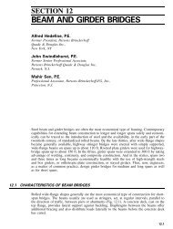
The elastic buckling moment (M e ~) of a simply supported<br />
singly symmetric I-beam or T-beam bent about <strong>the</strong> jc-axis<br />
perpendicular <strong>to</strong> <strong>the</strong> web as shown in Figure 5.la with<br />
equal and opposite end moments and of unbraced length (L)<br />
is given in Refs 5.1 and 5.2 and is equal <strong>to</strong><br />
M e =<br />
2<br />
ndy /, n 2 EC u<br />
- + 1 + (5.4)<br />
2 y ' V GJL 2 ;<br />
where<br />
(5.5)
y<br />
A<br />
Lateral<br />
But: tiling<br />
Mode<br />
y<br />
A<br />
Lateral<br />
Buckling<br />
Mode<br />
l<br />
I, a Tern 1<br />
Bucklm<br />
Mode<br />
Lateral<br />
Buckling<br />
Mode<br />
t<br />
' \1<br />
--> <<br />
tb)<br />
FIGURE 5.1 Lateral buckling modes and axes: (a) I and T-sections<br />
bent about x-axis; (b) hat and inverted hat sections bent about y<br />
axis.<br />
and / , J and C w are <strong>the</strong> minor axis second moment of area,<br />
<strong>the</strong> <strong>to</strong>rsion constant, and warping constant, respectively.<br />
The value of S is positive when <strong>the</strong> larger flange is in<br />
compression, is zero for doubly symmetric beams, and is<br />
negative when <strong>the</strong> larger flange is in tension.<br />
The single-symmetry parameter (f} x ) is a crosssectional<br />
parameter defined by<br />
f<br />
(5.6)<br />
In <strong>the</strong> case of doubly symmetric beams, /3 X is zero and Eq.<br />
(5.4) simplifies <strong>to</strong><br />
M.=<br />
GJL 2 (5.7)<br />
In <strong>the</strong> case of simply supported beams subjected <strong>to</strong> nonuniform<br />
moment, Eq. (5.7) can be modified by multiplying by
<strong>the</strong> fac<strong>to</strong>r C&, which allows for <strong>the</strong> nonuniform distribution<br />
of bending moment in <strong>the</strong> beam:<br />
(5.8)<br />
The Q, fac<strong>to</strong>r is discussed in Section 5.2.2.<br />
The elastic buckling moments (M e ) in Section C3.1.2 of<br />
<strong>the</strong> <strong>AISI</strong> <strong>Specification</strong> are expressed in terms of <strong>the</strong> elastic<br />
buckling stresses (a ex , a ey , a t ). These stresses for an axially<br />
loaded compression member are fully described in Chapter<br />
7. For example, Eq. [C3.1.2(6)] of <strong>the</strong> <strong>AISI</strong> <strong>Specification</strong><br />
gives <strong>the</strong> elastic buckling moment for a singly symmetric<br />
section bent about <strong>the</strong> symmetry axis, or a doubly<br />
symmetric section bent about <strong>the</strong> jc-axis,<br />
(5.9)<br />
By substituting a and a t from Eqs. [C3.1.2(9)] and<br />
[03.1.2(10)] of <strong>the</strong> <strong>AISI</strong> <strong>Specification</strong>, Eq. (5.9) becomes<br />
GJ(K,L,<br />
(5.10)<br />
This is <strong>the</strong> same as Eq. (5.8) except that <strong>the</strong> unbraced<br />
length (L) is replaced by K y L y for <strong>the</strong> effective length about<br />
<strong>the</strong> j-axis, and K t L t for <strong>the</strong> effective length for twisting, as<br />
appropriate. Hence, Eq. [C3.1.2(6)] in Section C3.1.2 of <strong>the</strong><br />
<strong>AISI</strong> <strong>Specification</strong> is a more general version of Eq. (5.8).<br />
As a second example, Eq. [C3.1.2(7)] of <strong>the</strong> <strong>AISI</strong><br />
<strong>Specification</strong> gives M e for a singly symmetric section bent<br />
about <strong>the</strong> centroidal j-axis perpendicular <strong>to</strong> <strong>the</strong> symmetry<br />
jc-axis, such as for <strong>the</strong> hat sections in Figure 5.1b, as<br />
where j equals /? /2 and /? is given by Eq. (5.6) with x and y<br />
interchanged, and C s is +1 or — 1 depending on whe<strong>the</strong>r <strong>the</strong><br />
moment causes compression or tension on <strong>the</strong> shear center
side of <strong>the</strong> centroid. Substituting a ex and a t from Eqs.<br />
[03.1.2(8)] and [03.1.2(10)] of <strong>the</strong> <strong>AISI</strong> <strong>Specification</strong> gives<br />
for Eq. (5.11)<br />
M<br />
n^/EI xGJ<br />
K X L X<br />
7r
IE \J£<br />
M, Bending Moment Diagram<br />
-1VL<br />
fa)<br />
Load per unit length = w<br />
U2 1/2<br />
L/3 L73 L/3<br />
Brace point <strong>to</strong>r<br />
central brace<br />
B run: poi nl foi 1<br />
thjrd point<br />
bracing<br />
I<br />
j<br />
!<br />
-*<br />
Bending Moment<br />
(h)<br />
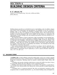
FIGURE 5.2 Simply supported beams: (a) beam under moment<br />
gradient; (b) beam under uniformly distributed load.<br />
where I yc is <strong>the</strong> second moment of area of <strong>the</strong> compression<br />
portion of <strong>the</strong> section about <strong>the</strong> centroidal axis of <strong>the</strong> full<br />
section parallel <strong>to</strong> <strong>the</strong> web, using <strong>the</strong> full unreduced<br />
section. This equation can be derived from Eq. (5.8) by<br />
putting J = 0, C w = I y d 2 /4:, and I yc = I y /2, and including an
additional fac<strong>to</strong>r | <strong>to</strong> allow for <strong>the</strong> fact that a Z-section has<br />
an inclined principal axis, whereas I yc is computed about<br />
<strong>the</strong> centroidal axis parallel <strong>to</strong> <strong>the</strong> web.<br />
5.2.2 Continuous Beams and Braced Simply<br />
Suppported Beams<br />
In practice, beams are not usually subjected <strong>to</strong> uniform<br />
moment or a linear moment distribution and are not always<br />
restrained by simple supports. Hence, if an accurate analysis<br />
of <strong>to</strong>rsional-flexural buckling is <strong>to</strong> be performed, <strong>the</strong><br />
following effects should be included:<br />
(a) Type of beam support, including simply<br />
supported, continuous, and cantilevered<br />
(b) Loading position, including <strong>to</strong>p flange, shear<br />
center, and bot<strong>to</strong>m flange<br />
(c) Positioning and type of lateral braces<br />
(d) Restraint provided by sheathing, including <strong>the</strong><br />
membrane, shear, and flexural stiffnesses<br />
A method of finite element analysis of <strong>the</strong> <strong>to</strong>rsional-flexural<br />
buckling of continuously restrained beams and beamcolumns<br />
has been described in Ref. 5.4 and was applied <strong>to</strong><br />
<strong>the</strong> buckling of simply supported purlins with diaphragm<br />
restraints in Ref. 5.5 and continuous purlins in Ref. 5.3.<br />
The element used in <strong>the</strong>se references is shown in Figure<br />
5.3a and shown subjected <strong>to</strong> loading in Figure 5.3b. The<br />
loading allows for a uniformly distributed load located a<br />
distance a below <strong>the</strong> shear center.<br />
A computer program PRFELB has been developed at<br />
<strong>the</strong> University of Sydney <strong>to</strong> perform a <strong>to</strong>rsional-flexural<br />
buckling analysis of beam-columns and plane frames using<br />
<strong>the</strong> <strong>the</strong>ory described in Refs. 5.2 and 5.4. The detailed<br />
method of operation of <strong>the</strong> program is described in Ref. 5.6.<br />
The method has been applied <strong>to</strong> <strong>the</strong> buckling of simply<br />
supported beams subjected <strong>to</strong> uniformly distributed loads<br />
as shown in Figure 5.2b <strong>to</strong> determine suitable C b fac<strong>to</strong>rs for
Ceiitroid.il axis—<br />
Sfieur center axis<br />
Riglil liuiid rule<br />
positive rolfitirm<br />
Right hiind rule<br />
positive Title uf<br />
change of rotation<br />
V<br />
•><br />
Cemroidal axis<br />
Shear center axis<br />
v,<br />
h<br />
1<br />
J7<br />
11<br />
Dnit'tirm<br />
\<br />
Load11<br />
third-point bracing. Each brace, including <strong>the</strong> end supports,<br />
was assumed <strong>to</strong> prevent both lateral and <strong>to</strong>rsional deformation.<br />
The element subdivisions used in <strong>the</strong> analysis are<br />
shown in Figure 5.4 for both central and third-point<br />
bracing. The resulting lateral deflections of <strong>the</strong> shear<br />
center in <strong>the</strong> buckling mode are also shown in Figure 5.4.<br />
The computed buckling loads were <strong>the</strong>n converted <strong>to</strong><br />
buckling moments which were substituted in<strong>to</strong> Eq. (5.8) <strong>to</strong><br />
compute C b values for each configuration analyzed. The<br />
resulting C b values are summarized in Table 5.1. The term<br />
///}/<br />
Element subdivision<br />
ri brad ng points<br />
LiiLeral deflection<br />
of fAtmtr t;ftTiter<br />
E'lan<br />
(a)<br />
s//S/<br />
Element subdivision<br />
and bracing points<br />
T<br />
a<br />
a<br />
L;ite.! al<br />
of shear earner<br />
PltlJS<br />
(b)<br />
FIGURE 5.4 Intermediately braced simply supported beams: (a)<br />
buckling mode—central brace; (b) buckling mode—third-point<br />
bracing.
TABLE 5.1 C b Fac<strong>to</strong>rs for Simply Supported Beams Uniformly Loaded<br />
Within <strong>the</strong> Span<br />
Loading<br />
position<br />
No<br />
bracing<br />
a — L<br />
One<br />
central<br />
brace<br />
a = 0.5L<br />
Third point<br />
bracing<br />
a = 0.33L<br />
Tension flange<br />
Shear center<br />
Compression flange<br />
1.92<br />
1.22<br />
0.77<br />
1.59<br />
1.37<br />
1.19<br />
1.47<br />
1.37<br />
1.28<br />
a in Table 5.1 is <strong>the</strong> bracing interval which replaces <strong>the</strong><br />
length (L) in Eq. (5.8).<br />
The C b fac<strong>to</strong>rs become larger as <strong>the</strong> loading moves<br />
from <strong>the</strong> compression flange <strong>to</strong> <strong>the</strong> tension flange since <strong>the</strong><br />
buckling load and, hence, buckling moment are increased.<br />
For <strong>the</strong> case of central bracing, <strong>the</strong> two half-spans<br />
buckle equally as shown in Figure 5.4a, and hence no<br />
elastic restraint is provided by one on <strong>the</strong> o<strong>the</strong>r. However,<br />
for <strong>the</strong> case of third-point bracing, <strong>the</strong> C b fac<strong>to</strong>r has been<br />
computed for <strong>the</strong> central section between braces which is<br />
elastically restrained by <strong>the</strong> end sections, which are more<br />
lightly loaded, as shown in Figure 5.2b. If <strong>the</strong> Q, fac<strong>to</strong>r was<br />
computed for <strong>the</strong> central section, not accounting for <strong>the</strong><br />
restraint provided by <strong>the</strong> end sections, <strong>the</strong>n <strong>the</strong> Q, fac<strong>to</strong>rs<br />
computed would be much closer <strong>to</strong> 1.0, since <strong>the</strong> central<br />
section is subjected <strong>to</strong> nearly uniform bending as shown in<br />
Figure 5.2b.<br />
In addition <strong>to</strong> <strong>the</strong> restraint provided by braces,<br />
restraint is also provided by <strong>the</strong> sheathing throughfastened<br />
<strong>to</strong> one flange. The restraint provided by <strong>the</strong><br />
sheathing is shown in Figure 5.5. If <strong>the</strong> sheathing has an<br />
adequate diaphragm (shear) stiffness (k ry ) in its plane, as<br />
defined in Figures 5.5a and 5.5b, it prevents lateral displacement<br />
of <strong>the</strong> flange <strong>to</strong> which it is connected. Fur<strong>the</strong>r, if <strong>the</strong><br />
sheathing has an adequate flexural stiffness (k rs ) as defined<br />
in Figure 5.5c, and is effectively connected <strong>to</strong> <strong>the</strong> purlin, it
' Line of support<br />
Purlin<br />
Purlin<br />
,' I,ine of support<br />
(a)<br />
m 1,<br />
A<br />
^-*-^ ^^ ^^<br />
bL<br />
FIGURE 5.5 Sheathing stiffness: (a) plan of sheathing; (b) sheathing<br />
shear stiffness (& ); (c) sheathing flexural stiffness (^).<br />
can provide <strong>to</strong>rsional restraint <strong>to</strong> <strong>the</strong> purlin. These stiffnesses<br />
can be incorporated in <strong>the</strong> finite element analysis<br />
described above <strong>to</strong> simulate <strong>the</strong> effect of sheathing.<br />
A finite element analysis has been performed for <strong>the</strong><br />
four-span continuous lapped purlin shown in Figure 5.6a
Sheathing screw fastened tc> trtp flange<br />
\ "<br />
1 ,ap<br />
Lap<br />
i i<br />
End span<br />
• = Lalcrul und tursional brace<br />
Interior span<br />
"T inward<br />
- outward |<br />
Lateral<br />
deflection<br />
ot'centroid<br />
Twist an ale<br />
Lateral<br />
deflection<br />
of cenrroid<br />
Twisr<br />
FIGURE 5.6 BMD and buckling modes for half-beam: (a) element<br />
subdivision; (b) BMD; (c) buckling modes.<br />
by treating it as a doubly symmetric beam. It is restrained<br />
by bracing as well as sheathing on <strong>the</strong> <strong>to</strong>p flange. The<br />
sheathing was assumed <strong>to</strong> provide a diaphragm shear<br />
stiffness of <strong>the</strong> type shown in Figure 5.5b, but no flexural<br />
stiffness of <strong>the</strong> type shown in Figure 5.5c. The loading was<br />
located at <strong>the</strong> level of <strong>the</strong> sheathing. The bending moment<br />
diagram is shown in Figure 5.6b, and <strong>the</strong> resulting buck-
ling modes for both inward and outward loading are shown<br />
in Figure 5.6c. In <strong>the</strong> case of outward loading, buckling<br />
occurs mainly in <strong>the</strong> end span as a result of its unrestrained<br />
compression flange. However, for inward loading,<br />
buckling occurs mainly at <strong>the</strong> first interior support where<br />
<strong>the</strong>re is a large negative moment and an unrestrained<br />
compression flange. The buckling loads for both inward<br />
and outward loading are approximately <strong>the</strong> same.<br />
To analyze problems of this type in practice without<br />
recourse <strong>to</strong> a finite element analysis, <strong>the</strong> C b fac<strong>to</strong>r has been<br />
M,<br />
(a)<br />
(b)<br />
FIGURE 5.7 Bending moment distributions: (a) positive moment<br />
(or negative) alone; (b) positive and negative moments.
included in Section C3.1.2 as in Eqs. (5.8) and (5.15). The<br />
C b fac<strong>to</strong>r is<br />
b<br />
12.5M max<br />
2.5M max + 3M A + 4M B + 3M C ^ '<br />
}<br />
where M max , M A , M B , and M c are <strong>the</strong> absolute values of<br />
moment shown in Figures 5.7a and b. Equation (5.16) is<br />
Equation (C3.1.2-11) of <strong>the</strong> <strong>AISI</strong> <strong>Specification</strong> and was<br />
developed by Kirby and Ne<strong>the</strong>rcot (Ref. 5.7).<br />
5.2.3 Bending Strength Design Equations<br />
The interaction of yielding and lateral buckling has not<br />
been thoroughly investigated for cold-formed sections.<br />
Consequently, <strong>the</strong> design approach adopted in <strong>the</strong> <strong>AISI</strong><br />
<strong>Specification</strong> is based on <strong>the</strong> Johnson parabola but fac<strong>to</strong>red<br />
by 10/9 <strong>to</strong> reflect partial plastification of <strong>the</strong> section in<br />
bending (Ref. 5.8).<br />
The set of beam design equations in Section C3.1.2 of<br />
<strong>the</strong> <strong>AISI</strong> <strong>Specification</strong> is<br />
M y forM e >2.78My (5.17)<br />
M c =\<br />
10MA<br />
36MJ<br />
for 2.78M y > M e > 0.56M y (5.18)<br />
M e forM e
1.0<br />
0.8<br />
Elastic<br />
\ Buckling [M e )<br />
\<br />
Parr II<br />
,£<br />
'j<br />
S<br />
0.6<br />
0.4<br />
Yielding (M y )<br />
<strong>AISI</strong>-19%<br />
0.2<br />
<strong>AISI</strong> M c<br />
Eurocude 3 ,.<br />
Part 1 3<br />
*>• Rtl<br />
I I 1 I ! I 1 I I I I I I I I<br />
0 0,2 0.4 0.6 (LK__ 1.0 1.2 1.4 1.6<br />
FIGURE 5.8<br />
Comparison of beam design curves.<br />
5.3 BASIC BEHAVIOR OF C- AND Z-SECTION<br />
FLEXURAL MEMBERS<br />
5.3.1 Linear Response of C- and Z-Sections<br />
5.3.1.1 General<br />
Two basic section shapes are normally used for flexural<br />
members. They are Z-sections, which are point-symmetric,<br />
and C-sections, which are singly symmetric. For wind<br />
uplift, loading is usually perpendicular <strong>to</strong> <strong>the</strong> sheathing<br />
and parallel with <strong>the</strong> webs of <strong>the</strong> C- and Z-sections. If <strong>the</strong>re<br />
is no lateral or <strong>to</strong>rsional restraint from <strong>the</strong> sheathing, Z-<br />
sections will move vertically and deflect laterally as a result<br />
of <strong>the</strong> inclined principal axes, while C-sections will move<br />
vertically and twist as a result of <strong>the</strong> eccentricity of <strong>the</strong> load<br />
from <strong>the</strong> shear center. If <strong>the</strong>re is full lateral and <strong>to</strong>rsional<br />
restraint, both C- and Z-sections will bend in a plane<br />
parallel with <strong>the</strong>ir webs, and simple bending <strong>the</strong>ory based<br />
on <strong>the</strong> section modulus computed for an axis perpendicular
<strong>to</strong> <strong>the</strong> web can be used <strong>to</strong> compute <strong>the</strong> bending stress and<br />
shear flow distributions in <strong>the</strong> section. If <strong>the</strong> sections have<br />
<strong>the</strong> same thickness, flange width, web depth, and lip width,<br />
<strong>the</strong>n <strong>the</strong> shear flow distributions are approximately <strong>the</strong><br />
same for both sections.<br />
5.3.1.2 Sections with Lateral Restraint Only<br />
In order <strong>to</strong> investigate <strong>the</strong> basic linear behavior of C- and<br />
Z-sections when full lateral restraint is applied at <strong>the</strong> <strong>to</strong>p<br />
flange with no <strong>to</strong>rsional restraint, simply supported C- and<br />
Z-sections subjected <strong>to</strong> uplift along <strong>the</strong> line of <strong>the</strong> web and<br />
laterally restrained at <strong>the</strong> <strong>to</strong>p flange have been analyzed<br />
with a linear elastic matrix displacement analysis which<br />
includes thin-walled tension (Refs. 5.12 and 5.13). The<br />
models used in <strong>the</strong> analysis are shown in Figure 5.9,<br />
where <strong>the</strong> sections have been subdivided in<strong>to</strong> 20 elements<br />
and a lateral restraint is provided at each of <strong>the</strong> 19 internal<br />
nodes at <strong>the</strong> points where <strong>the</strong> uplift forces are applied. The<br />
uplift forces are statically equivalent <strong>to</strong> a uniformly distributed<br />
force (w) of 1131b/in. The longitudinal stress distributions<br />
at <strong>the</strong> central cross sections are shown in Figure 5.10<br />
and are almost identical for C- and Z-sections. The stress<br />
distributions show that <strong>the</strong> <strong>to</strong>p flange remains in uniform<br />
stress, whereas <strong>the</strong> bot<strong>to</strong>m flange undergoes transverse<br />
bending in addition <strong>to</strong> compression from <strong>the</strong> vertical<br />
component of bending. If plain C- and Z-sections were<br />
compared, <strong>the</strong> stress distributions would be identical. The<br />
lateral displacement at point C on <strong>the</strong> bot<strong>to</strong>m flange of<br />
<strong>the</strong> sections in Figure 5.9 was computed <strong>to</strong> be 2.5 in. for<br />
<strong>the</strong> C-section and 2.4 in. for <strong>the</strong> Z-section. It can be<br />
concluded that C- and Z-sections with lateral restraint<br />
only from sheathing attached <strong>to</strong> one flange tend <strong>to</strong> behave<br />
similarly, whereas C- and Z-sections without restraint<br />
behave differently.
79in<br />
FIGURE 5.9 Simply supported beam models: (a) C-section;<br />
(b) Z-section.
17,1<br />
Q<br />
17,1 16,8<br />
If:.?<br />
17,1 10.4<br />
T<br />
15.2<br />
2-1. K<br />
9.4.4 '<br />
(a)<br />
FIGURE 5.10 Longitudinal stress distributions at central cross<br />
section of beam models: (a) C-section, (b) Z-section.<br />
(h)<br />
5.3.1.3 Sections with Lateral and Torsional<br />
Restraint<br />
The magnitude of <strong>the</strong> <strong>to</strong>rsional restraint will govern <strong>the</strong><br />
degree <strong>to</strong> which <strong>the</strong> unrestrained flange moves laterally for<br />
both C- and Z-sections. For C- and Z-sections under <strong>the</strong><br />
wind uplift and restrained both laterally and <strong>to</strong>rsionally by<br />
sheathing, deformation will tend <strong>to</strong> be as shown in Figure<br />
5.11a. The forces per unit length acting on <strong>the</strong> purlins as<br />
shown in Figure 5. lib are q, representing uplift, p, representing<br />
prying, and r, representing lateral restraint at <strong>the</strong><br />
<strong>to</strong>p flange. The prying forces can be converted in<strong>to</strong> a<br />
statically equivalent <strong>to</strong>rque (pbf/2) as shown in Figure<br />
5. lie. If <strong>the</strong> line of action of <strong>the</strong> uplift force (q) and lateral
estraint force (r) are moved <strong>to</strong> act through <strong>the</strong> shear center<br />
for both sections, <strong>the</strong>n a statically equivalent <strong>to</strong>rque (m t )<br />
results, as shown in Figure 5. lid, and is given by Eq. (5.20)<br />
for a Z-section and by Eq. (5.21) for a C-section:<br />
(5.20)<br />
(5.2D<br />
The pbf/2, term is <strong>the</strong> <strong>to</strong>rque resulting from <strong>the</strong> prying<br />
force. The rb w /2 term is <strong>the</strong> <strong>to</strong>rque resulting from <strong>the</strong><br />
eccentricity of <strong>the</strong> restraining force from <strong>the</strong> shear center.<br />
The qbf/2, term is <strong>the</strong> <strong>to</strong>rque resulting from <strong>the</strong> eccentricity<br />
of <strong>the</strong> line of <strong>the</strong> screw fastener, presumed at <strong>the</strong> center of<br />
<strong>the</strong> flange, from <strong>the</strong> web centerline. The term qd s in Eq.<br />
(5.21) is <strong>the</strong> <strong>to</strong>rque resulting from <strong>the</strong> eccentricity of <strong>the</strong><br />
shear center of <strong>the</strong> C-section from <strong>the</strong> web centerline. Since<br />
<strong>the</strong> forces in Figure 5. lid act through <strong>the</strong> shear center of<br />
each section, <strong>the</strong> value of m t must be zero if <strong>the</strong> section does<br />
not twist. Hence, <strong>the</strong> different components of Eqs. (5.20)<br />
and (5.21) must produce a zero net result for mt for<br />
untwisted sections.<br />
For <strong>the</strong> Z-section, <strong>the</strong> value of r in Eq. (5.20) is given<br />
by Eq. (5.22) for a section which is untwisted and braced<br />
laterally:<br />
r = -^ (5.22)<br />
*x<br />
Using Eqs. (5.20) and (5.22) and assuming that <strong>the</strong> value of<br />
—I xy /I x is equal <strong>to</strong> bf/b w , where <strong>the</strong> x- and j-axes are as<br />
shown in Figure 5. lib, so that <strong>the</strong> sign of I xy is negative, <strong>the</strong>n<br />
<strong>the</strong> second and third terms in Eq. (5.20) add <strong>to</strong> zero. Hence,<br />
<strong>the</strong> first term in Eq. (5.20) (prying force term) is zero if mt is<br />
zero. Consequently, since it can be shown that <strong>the</strong> second and<br />
third terms in Eq. (5.20) cancel approximately for conventional<br />
Z-sections with <strong>the</strong> screw fastener in <strong>the</strong> center of <strong>the</strong><br />
flange, <strong>the</strong> prying force will be small for Z-sections before<br />
structural instability of <strong>the</strong> unrestrained flange occurs.
1 1 1 1 1 1 1 f<br />
U:<br />
q+n i IP P<br />
J<br />
(h)<br />
V<br />
gb r<br />
Cd)<br />
FIGURE 5.11 C- and Z-section statics: (a) deformation under<br />
uplift; (b) forces acting on purlins (a); (c) static equivalent of (b);<br />
(d) static equivalent of (c) with forces through shear center (S).
By comparison, <strong>the</strong> value of r in Eq. (5.21) for a C-<br />
section is zero if <strong>the</strong> section remains untwisted. Hence, for<br />
m t <strong>to</strong> be zero, <strong>the</strong> first term in Eq. (5.21) (prying force term)<br />
must balance with <strong>the</strong> third and fourth terms in Eq. (5.21).<br />
That is, <strong>the</strong> <strong>to</strong>rque from <strong>the</strong> prying forces is required <strong>to</strong><br />
counterbalance <strong>the</strong> <strong>to</strong>rque from <strong>the</strong> eccentricity of <strong>the</strong> uplift<br />
force in <strong>the</strong> center of <strong>the</strong> flange from <strong>the</strong> shear center.<br />
Consequently, <strong>the</strong> prying forces are much greater for C-<br />
sections, than <strong>the</strong>y are for Z-sections before structural<br />
instability of <strong>the</strong> unrestrained flange occurs.<br />
5.3.2 Stability Considerations<br />
When studying <strong>the</strong> lateral stability of C- and Z-section<br />
flexural members restrained by sheathing, two basically<br />
different models of <strong>the</strong> buckling mode have been developed.<br />
I J x^'<br />
(ii)<br />
(iii)<br />
(a)<br />
d)<br />
D model<br />
(b)<br />
FIGURE 5.12 C-section twisting deformations: (a) dis<strong>to</strong>rted (D)<br />
section model; (b) undis<strong>to</strong>rted (U) section model.
0")<br />
model<br />
FIGURE 5.13 Z-section twisting deformations: (a) dis<strong>to</strong>rted (D)<br />
section model; (b) undis<strong>to</strong>rted (U) section model.<br />
These are <strong>the</strong> dis<strong>to</strong>rted section model (D model) shown in<br />
Figures 5.12a and 5.13a for C- and Z-sections, respectively,<br />
and <strong>the</strong> undis<strong>to</strong>rted section model (U model) shown in<br />
Figures 5.12b and 5.13b for C- and Z-sections, respectively.<br />
The D model is similar <strong>to</strong> <strong>the</strong> behavior of sheeted purlins as<br />
observed in tests. The U model is based on <strong>the</strong> well-known<br />
thin-walled beam <strong>the</strong>ories of Timoshenko (Ref. 3.6) and<br />
Vlasov (Ref. 5.14), so <strong>the</strong> stability can be computed by using<br />
<strong>the</strong> conventional stability <strong>the</strong>ory of thin-walled beams with<br />
undis<strong>to</strong>rted cross sections.<br />
The D model has required <strong>the</strong> development of a new<br />
stability model <strong>to</strong> account for <strong>the</strong> section dis<strong>to</strong>rtion which is<br />
not accounted for in <strong>the</strong> Timoshenko and Vlasov <strong>the</strong>ories.<br />
In <strong>the</strong> D model, <strong>the</strong> unrestrained flange is usually in<br />
compression for purlins subjected <strong>to</strong> wind uplift. Hence,
<strong>the</strong> compression flange will become unstable if <strong>the</strong> lateral<br />
restraint provided through <strong>the</strong> web is insufficient <strong>to</strong><br />
prevent column buckling of <strong>the</strong> unrestrained flange. The<br />
usual model for cases where <strong>the</strong> <strong>to</strong>rsional restraint<br />
provided by <strong>the</strong> sheathing is substantial is <strong>to</strong> consider <strong>the</strong><br />
unrestrained compression flange as a compression member<br />
supported by a continuous elastic restraint of stiffness K as<br />
shown in Figure 5.14b. The elastic restraint of stiffness K<br />
shown in Figure 5.14b consists of <strong>the</strong> stiffness of <strong>the</strong> web<br />
and <strong>the</strong> purlin-sheeting connection, and <strong>the</strong> flexural resistance<br />
of <strong>the</strong> sheathing.<br />
A design method for simply supported C-sections without<br />
bridging and subjected <strong>to</strong> uniformly distributed load<br />
was developed at Cornell University and is described in<br />
detail in Ref. 5.15. The method has been extended recently<br />
<strong>to</strong> continuous lapped C- and Z-sections, with and without<br />
T^<br />
Sheathing<br />
-h<br />
Torsion<br />
Vertical Bending<br />
Stage<br />
(a)<br />
Spring Nil<br />
K<br />
Flange<br />
element<br />
W(7)<br />
Conventional<br />
bending <strong>the</strong>ary<br />
with I computed<br />
Ibr [ivisred secrion<br />
'ibrsion Stage<br />
Vertical Bending Stag,e<br />
FIGURE 5.14<br />
(b) models.<br />
(b)<br />
D model of C-section under uplift: (a) deflection;
Flexural Members<br />
bridging, by Rousch and Hancock (Refs. 5.16—5.18). A brief<br />
summary of <strong>the</strong> method follows.<br />
As shown in Figure 5.14a, <strong>the</strong> deflected configuration<br />
is assumed <strong>to</strong> be <strong>the</strong> sum of a <strong>to</strong>rsion stage, which includes<br />
dis<strong>to</strong>rtion of <strong>the</strong> section as a result of flexure of <strong>the</strong> web,<br />
and a vertical bending stage. It is assumed that <strong>the</strong> <strong>to</strong>rsion<br />
stage is resisted by a flange element restrained by an<br />
elastic spring of stiffness K as shown in Figure 5.14b.<br />
FIGURE 5.15 Test of C-section—sheathing combination <strong>to</strong> determine<br />
spring stiffness (K).<br />
151
K<br />
J^Ur" -jW-iV Jjj&i<br />
JWA^<br />
A „! JL L<br />
(b)<br />
FIGURE 5.16 Idealized beam-column in D model: (a) forces and<br />
restraint on flange element; (b) plan of assumed deflected shape.<br />
The flange element is assumed <strong>to</strong> be subjected <strong>to</strong> a distributed<br />
lateral load w(z) per unit length and a distributed<br />
axial force p(z) per unit length as shown in Figure 5.16a. It<br />
deflects u in its own plane as shown in Figure 5.16b. The<br />
<strong>to</strong>rsional rotation, and hence <strong>the</strong> <strong>to</strong>rsional stiffness (GJt),<br />
of <strong>the</strong> flange element is ignored.<br />
The spring stiffness K depends upon <strong>the</strong><br />
(a) Flexibility of <strong>the</strong> web<br />
(b) Flexibility of <strong>the</strong> connection between <strong>the</strong> tension<br />
flange and <strong>the</strong> sheathing<br />
(c) Flexibility of <strong>the</strong> sheathing<br />
A test of a short length of purlin through-fastened <strong>to</strong><br />
sheathing as shown in Figure 5.15 is required <strong>to</strong> assess<br />
this <strong>to</strong>tal flexibility and, hence, K.<br />
The flange element is <strong>the</strong>n analyzed as a beam-column<br />
as shown in Figure 5.16. In Ref. 5.15, <strong>the</strong> deflected shape<br />
(u) of <strong>the</strong> beam-column is assumed <strong>to</strong> be a sine curve, and<br />
an energy analysis of <strong>the</strong> system is performed, including
<strong>the</strong> flexural strain energy of <strong>the</strong> flange element, <strong>the</strong> strain<br />
energy of <strong>the</strong> elastic spring, <strong>the</strong> potential energy of <strong>the</strong><br />
lateral loads [w(X)], and <strong>the</strong> potential energy of <strong>the</strong> axial<br />
loads \p(z)]. In Refs 5.16-5.18, a finite element beamcolumn<br />
model is used <strong>to</strong> determine <strong>the</strong> deflected shape (u)<br />
of <strong>the</strong> unrestrained flange.<br />
The failure criteria involve comparing <strong>the</strong> maximum<br />
stress at <strong>the</strong> flange-web junction with <strong>the</strong> local buckling<br />
failure stress (F bw ), and <strong>the</strong> maximum stress at <strong>the</strong> flange<br />
lip junction with <strong>the</strong> dis<strong>to</strong>rtional buckling failure stress.<br />
5.4 BRACING<br />
As described in Section 1.7.4, bracing of beams can be used<br />
<strong>to</strong> increase <strong>the</strong> <strong>to</strong>rsional-flexural buckling load. In addition,<br />
non-doubly-symmetric sections, such as C- and Z-sections,<br />
twist or deflect laterally under load as a consequence of <strong>the</strong><br />
loading which is not located through <strong>the</strong> shear center for C-<br />
sections or not in a principal plane for Z-sections. Consequently,<br />
bracing can be used <strong>to</strong> minimize lateral and<br />
<strong>to</strong>rsional deformations and <strong>to</strong> transmit forces and <strong>to</strong>rques<br />
<strong>to</strong> supporting members.<br />
For C- and Z-sections used as beams, two basic situations<br />
exist as specified in Section D.3.2 of <strong>the</strong> <strong>AISI</strong> <strong>Specification</strong>.<br />
(a) When <strong>the</strong> <strong>to</strong>p flange is connected <strong>to</strong> deck or<br />
sheathing in such a way that <strong>the</strong> sheathing effectively<br />
restrains lateral deflection of <strong>the</strong> connected<br />
flange as described in Section D3.2.1<br />
(b) When nei<strong>the</strong>r flange is so connected and bracing<br />
members are used <strong>to</strong> support <strong>the</strong> member as<br />
described in Section D3.2.2<br />
A full discussion of bracing requirements for metal roof and<br />
wall systems is given in Section 10.4.<br />
The formulae for <strong>the</strong> design of braces specified in<br />
Section D3.2.2 are based on an analysis of <strong>the</strong> <strong>to</strong>rques
and lateral forces induced in a C- or Z-section, respectively,<br />
assuming that <strong>the</strong> braces completely resist <strong>the</strong>se forces. For<br />
<strong>the</strong> simple case of a concentrated load acting along <strong>the</strong> line<br />
of <strong>the</strong> web of a C-section as shown in Figure 5.17a, <strong>the</strong><br />
brace connected <strong>to</strong> <strong>the</strong> C-section must resist a <strong>to</strong>rque equal<br />
<strong>to</strong> <strong>the</strong> concentrated force times its distance from <strong>the</strong> shear<br />
center. For <strong>the</strong> case of a vertical force acting along <strong>the</strong> line<br />
I'm<br />
m<br />
P<br />
.^ Shear<br />
"" center<br />
(a)<br />
A<br />
x. y are<br />
central da I axes<br />
FIGURE 5.17 Theoretical bracing forces at a point of concentrated<br />
load: (a) C-section forces; (b) Z-section forces.
of <strong>the</strong> web of a Z-section as shown in Figure 5.17b, <strong>the</strong> brace<br />
must resist <strong>the</strong> load tending <strong>to</strong> cause <strong>the</strong> section <strong>to</strong> deflect<br />
perpendicular <strong>to</strong> <strong>the</strong> web. Section D3.2.2 also specifies how<br />
<strong>the</strong> bracing forces should be calculated when <strong>the</strong> loads are<br />
not located at <strong>the</strong> brace points or are uniformly distributed<br />
loads.<br />
5.5 INELASTIC RESERVE CAPACITY<br />
5.5.1 Sections with Flat Elements<br />
As described in Section 1.7.10, a set of rules <strong>to</strong> allow for <strong>the</strong><br />
inelastic reserve capacity of flexural members is included in<br />
Section C3.1.1(b) of <strong>the</strong> <strong>AISI</strong> <strong>Specification</strong>. These rules are<br />
based on <strong>the</strong> <strong>the</strong>ory and tests in Ref. 5.19.<br />
<strong>Cold</strong>-formed sections are generally not compact as are<br />
<strong>the</strong> majority of hot-rolled sections and hence are not<br />
capable of participating in plastic design. However, <strong>the</strong><br />
neutral axis of cold-formed sections may not be at middepth,<br />
and initial yielding may take place in <strong>the</strong> tension<br />
flange. Also, since <strong>the</strong> web and flange thicknesses are <strong>the</strong><br />
same for cold-formed sections, <strong>the</strong> ratio of web area <strong>to</strong> <strong>to</strong>tal<br />
area is larger than for hot-rolled sections. The inelastic<br />
reserve capacity of cold-formed sections may <strong>the</strong>refore be<br />
greater than that for doubly symmetric hot-rolled sections.<br />
Consequently an allowance for inelastic reserve capacity<br />
may produce substantial gains in capacity for cold-formed<br />
sections even if <strong>the</strong> maximum strain in <strong>the</strong> section is<br />
limited in keeping with <strong>the</strong> reduced ductility of coldformed<br />
steel sections.<br />
Tests on cold-formed hat sections were reported in Ref.<br />
5.19 and are shown in Figure 5.18a where <strong>the</strong> ratio (CL) of<br />
<strong>the</strong> maximum compressive strain <strong>to</strong> <strong>the</strong> yield strain has<br />
been plotted against <strong>the</strong> compression flange slenderness for<br />
a range of section slenderness values. An approximate<br />
lower bound <strong>to</strong> <strong>the</strong>se tests is shown, which is <strong>the</strong> basis of<br />
Section C3.1.1(b) in <strong>the</strong> <strong>AISI</strong> <strong>Specification</strong>. For sections
Section<br />
C:U.](b)<strong>AISI</strong><br />
__^<br />
* Test <strong>to</strong> M p<br />
» Tfesr <strong>to</strong> 0.85Mp - l,OM r<br />
0<br />
30 34 36 38 40 42 44<br />
l>/t for 36 ksi <strong>Steel</strong><br />
CyCy<br />
Fj<br />
Neutral<br />
uxs<br />
--F v<br />
Section Strain Stress<br />
(b)<br />
_y<br />
___Nfutra1_<br />
axis f<br />
Strain<br />
Stress<br />
f < F u<br />
FIGURE 5.18 Stresses and strains for assessing inelastic reserve<br />
capacity: (a) compression strain fac<strong>to</strong>r for stiffened compression<br />
elements; (b) stress distribution for tension and compression<br />
flange yielded; (c) stress distribution for tension flange not<br />
yielded.<br />
with stiffened compression flanges with slenderness less<br />
than I.II/^F y /E, a maximum value of compression flange<br />
strain equal <strong>to</strong> three times <strong>the</strong> yield strain (C y = 3.0) is<br />
allowed. For sections with stiffened compression flanges
with slenderness greater than l.ZS/^Fy/E, <strong>the</strong> maximum<br />
compression flange strain is <strong>the</strong> yield strain (C y = 1.0). For<br />
intermediate slenderness values, linear interpolation<br />
should be used.<br />
From <strong>the</strong>se values of C y , <strong>the</strong> stress and strain distributions<br />
in Figures 5.18b and 5.18c can be determined. The<br />
stress distributions assume an ideally elastic-plastic material.<br />
The ultimate moment (M u ) causing a maximum<br />
compression strain of C y e y can <strong>the</strong>n be calculated from<br />
<strong>the</strong> stress distributions. Section C3.1.1(b) of <strong>the</strong> <strong>AISI</strong><br />
<strong>Specification</strong> limits <strong>the</strong> nominal flexural strength (M n ) <strong>to</strong><br />
1..25S e F' This limit requires that conditions (1)—(5) of<br />
Section C3.1.1(b) be satisfied. These limits ensure that<br />
o<strong>the</strong>r modes of failure such as <strong>to</strong>rsional-flexural buckling<br />
or web failure do not occur before <strong>the</strong> ultimate moment is<br />
reached. For sections with unstiffened compression flanges<br />
and multiple stiffened segments, Section C3.1.1(b) of <strong>the</strong><br />
<strong>AISI</strong> <strong>Specification</strong> requires that C y = I.<br />
5.5.2 Cylindrical Tubular Members<br />
Section C6.1 of <strong>the</strong> <strong>AISI</strong> <strong>Specification</strong> gives design rules for<br />
cylindrical tubular members in bending and includes <strong>the</strong><br />
inelastic reserve capacity for compact sections for which<br />
M n = l.25F y S f .<br />
The effective section modulus (S e ) nondimensionalized<br />
with respect <strong>to</strong> <strong>the</strong> full elastic section modulus (Sy-) has<br />
been plotted in Figure 5.19 versus <strong>the</strong> section slenderness<br />
(A s ) based on <strong>the</strong> outside diameter-<strong>to</strong>-thickness ratio (D/f)<br />
and <strong>the</strong> yield stress (F y ~). A test database provided by<br />
Sherman (Ref. 5.20) for constant moment and cantilever<br />
tests on electric resistance welds (ERW) and fabricated<br />
tubes has also been plotted on <strong>the</strong> figure. The most significant<br />
feature of <strong>the</strong> <strong>AISI</strong> <strong>Specification</strong> is that <strong>the</strong> full-section<br />
plastic moment capacity can be used for compact section<br />
tubes.
1,4<br />
<strong>AISI</strong> specification<br />
0.8<br />
0.6<br />
0.4<br />
0.2<br />
0,0<br />
^1.273<br />
My<br />
Constant MumenL TCJKLS<br />
+ ERW<br />
* Fabricated<br />
• Fabricated (Slender)<br />
Cantilever Tests [Welded Uases)<br />
« ERW<br />
50 100 150 200 250<br />
D F<br />
Cu<strong>to</strong>ff<br />
<strong>to</strong>r <strong>AISI</strong><br />
Specif icatinn<br />
300 350 400 4tt)<br />
FIGURE 5.19<br />
Circular hollow sections (bending).<br />
5.6 EXAMPLE: SIMPLY SUPPORTED<br />
C-SECTION BEAM<br />
Problem<br />
Determine <strong>the</strong> design load on <strong>the</strong> C-section beam in Example<br />
4.6.3 simply supported over a 25ft. span with one brace<br />
at <strong>the</strong> center and loaded on <strong>the</strong> tension flange as shown in<br />
Figure 5.20. Use <strong>the</strong> lateral buckling strength (Section<br />
3.1.2). The following section, equation, and table numbers<br />
refer <strong>to</strong> those in <strong>the</strong> <strong>AISI</strong> <strong>Specification</strong>.<br />
F y = 55 ksi<br />
L = 300 in.<br />
R = 0.1875 in.<br />
E = 29500 ksi<br />
H = 8 in.<br />
D = 0.625 in.<br />
G= 11300 ksi<br />
5=2.75 in.<br />
t = 0.060 in.
tit<br />
Uplift on t<br />
t mi i tt i t f t inn<br />
=L L^ I2ft6in<br />
Lateral 4 <strong>to</strong>rsional<br />
brace<br />
L y = Li = 12tt6in<br />
I. = 25t't<br />
BMD<br />
M H = L2qL"/12W<br />
M c = 15qL 2 /128<br />
1<br />
1<br />
t<br />
f<br />
Av 1<br />
1<br />
in<br />
' ~1<br />
^o<br />
X<br />
1 ————t- h<br />
V \<br />
\ Shear<br />
v center<br />
— •-<br />
-5-———^<br />
-• t<br />
~T<br />
r=R + ^<br />
FIGURE 5.20 C-section beam loading and dimensions: (a) loading<br />
and bending moment distribution; (b) centerline dimensions; (c)<br />
flat dimensions.<br />
Solution<br />
I. Area, Major, and Minor Axis Second Moments of Area<br />
and Torsion Constant of Full Section accounting for<br />
Rounded Corners (see Figure 5.20c)
= # + = 0.2175 in.<br />
z*<br />
h = H-(2r + 0 = 7.505 in.<br />
w = B-(2r + t) = 2.255 in.<br />
d = D- r +<br />
=0.378 in.<br />
I =<br />
= — = 0.342 in.<br />
= 2t 0.04m 3 h X<br />
- '| + 0.637.)<br />
2d) = 0.848 in.<br />
/ 7 \2 / 7 \2<br />
\^ /<br />
+ 2(0.149r 3 ) + 0.0833d 3 +-r(h- d) 2<br />
8.198 in. 4<br />
^(| + r)+ M (0.363r)<br />
+ M(M; + 1.637r) + d(w + 2r)j<br />
0.703 in.<br />
, \2 7y;3<br />
- + r) + — + 0.356r 3 + d(w + 2r) 2<br />
w(w + 1.637r) 2 + 0.149r 3 ]<br />
II.<br />
= 0.793 in. 4<br />
t 3<br />
J = —(h + 2w + 2d + 4w) = 0.00102 in. 4<br />
3<br />
Warping Constant and Shear Center Position for<br />
Section with Square Corners (see Figure 5.20b)<br />
a = H -t = 7.94 in.<br />
b = B-t = 2.69 in.<br />
c = D--= 0.595 in.
(3a 2 b + c(6a 2 - 8c 2 ))<br />
m =<br />
a 3 + 6a 2 6 + c(8c 2 - 12ac + 6a 2 )<br />
= 1.151 in.<br />
x<br />
a 2 6 2 *<br />
12<br />
2a 3 6 +3a 2 6 2 +1126c 3 +8ac 3<br />
+48afrc 2 +12a 2 c 2 +12a 2 6c +6a 3 c<br />
6a 2 6 + (a + 2c) 3 - 24ac 2<br />
= 10.362 in.<br />
x 0 = —(x + m) = —1.854 in.<br />
III. Design Load on Braced Beam<br />
Section C3.1.2 Lateral buckling strength<br />
A. Effective Lengths for Central Brace<br />
L,, = - = 150 in.<br />
L, = - = 150 in<br />
B. Buckling Stresses<br />
= - = 0.967 in.<br />
(LJr y )<br />
= 12.10 ksi<br />
(Eq. C3.1.2-9)<br />
+ '<br />
i. (Eq. C3.1.2-13)<br />
GJ<br />
1 + GJL<br />
2<br />
= 12.23 ksi(Eq. C3.1.2-10)
C. Cj, Fac<strong>to</strong>r for Uniformly Distributed Load (see<br />
Figure 5.20a)<br />
_ 2.5Mmax + 3M A + 4M B + 3M C<br />
(Eq. C3.1.2-11)<br />
M e = C b Ar 0^a^a- t = 50.202 kip-in. (Eq. C3.1.2-6)<br />
C. Critical Moment (M c )<br />
= S^ = 112.72 kip-in. (Eq. C3.1.2-5)<br />
= M e = 50.20 kip-in. since M e < 0.56 M y<br />
(Eq. C3.1.2-4)<br />
F =<br />
= 24.50 ksi<br />
D. Nominal Strength of Laterally Unbraced Segment<br />
S c is <strong>the</strong> effective section modulus at <strong>the</strong> stress<br />
F c = M c /Sf. Use calculation method in Example 4.6.3<br />
with / = 24.495 ksi.<br />
S c = 1.949 in. 3<br />
M n = S C F C = 47.741 kip-in.<br />
LRFD (> = 0.90<br />
ASD Q b = 1.67<br />
= o~r^ = 2 ' 541
REFERENCES<br />
5.1 Galambos, T. V., Structural Members and Frames,<br />
Prentice-Hall, Englewood Cliffs, New Jersey, 1968.<br />
5.2 Trahair, N. S., Flexural-Torsional Buckling, E. & F. N.<br />
Spon, 1993.<br />
5.3 Ings, N. L. and Trahair, N. S., Lateral buckling of<br />
restrained roof purlins, Thin-Walled <strong>Structures</strong>, Vol.<br />
2, No. 4, 1984, pp. 285-306.<br />
5.4 Hancock, G. J. and Trahair, N. S., Finite element<br />
analysis of <strong>the</strong> lateral buckling of continuously<br />
restrained beam-columns, Civil Engineering Transactions,<br />
Institution of Engineers, Australia, Vol.<br />
CE20, No. 2, 1978.<br />
5.5 Hancock, G. J. and Trahair, N. S., Lateral buckling of<br />
roof purlins with diaphragm restraints, Civil Engineering<br />
Transactions, Institution of Engineers,<br />
Australia, Vol. CE21, No. 1, 1979.<br />
5.6 Users Manual for Program PRFELB, Elastic Flexural-Torsional<br />
Buckling Analysis, Version 3.0,<br />
Center for Advanced Structural Engineering, Department<br />
of Civil Engineering, University of Sydney,<br />
1997.<br />
5.7 Kirby, P. A. and Ne<strong>the</strong>rcot, D. A., Design for Structural<br />
Stability, Wiley, New York, 1979.<br />
5.8 Galambos, T. V, Inelastic buckling of beams, Journal<br />
of <strong>the</strong> Structural Division, ASCE, 89(ST5), Oc<strong>to</strong>ber<br />
1963.<br />
5.9 Pekoz, T. B. and Sumer, O., Design Provisions for<br />
<strong>Cold</strong>-<strong>Formed</strong> <strong>Steel</strong> Columns and Beam-Columns,<br />
Final Report, Cornell University, submitted <strong>to</strong><br />
American Iron and <strong>Steel</strong> Institute, September<br />
1992.<br />
5.10 Kian, T. and Pekoz, T. B., Evaluation of Industry-<br />
Type Bracing Details for Wall Stud Assemblies, Final<br />
Report, Cornell University, submitted <strong>to</strong> American<br />
Iron and <strong>Steel</strong> Institute, January 1994.
5.11 Trahair, N. S., Lateral buckling strengths of<br />
unsheeted cold-formed beams, Engineering <strong>Structures</strong>,<br />
16(5), 1994, pp. 324-331.<br />
5.12 Baigent, A. H. and Hancock, G. J., Structural analysis<br />
of assemblages of thin-walled members, Engineering<br />
<strong>Structures</strong>, Vol. 4, No. 3, 1982.<br />
5.13 Hancock, G. J., Portal frames composed of coldformed<br />
channel and Z-sections, in <strong>Steel</strong> Framed<br />
<strong>Structures</strong>—Stability and Strength, (R. Narayanan,<br />
ed.), Elsevier Applied Science Publishers, London,<br />
1985, Chap. 8.<br />
5.14 Vlasov, V. Z., Thin-Walled Elastic Beams, Moscow<br />
(English translation, Israel Progam for Scientific<br />
Translation, Jerusalem), 1961.<br />
5.15 Pekoz, T. and P. Soroushian, Behavior of C- and Z-<br />
Purlins under Wind Uplift, Sixth International Specialty<br />
Conference on <strong>Cold</strong>-<strong>Formed</strong> <strong>Steel</strong> <strong>Structures</strong>, St<br />
Louis, MO, Nov. 1982.<br />
5.16 Rousch, C. J. and Hancock, G. J., Comparison of a<br />
non-linear Purlin Model with Tests, Proceedings<br />
12th International Specialty Conference on <strong>Cold</strong>-<br />
<strong>Formed</strong> <strong>Steel</strong> Structrures, St. Louis, MO, 1994, pp.<br />
121-149.<br />
5.17 Rousch, C. J. and Hancock, G. J., Determination of<br />
Purlin R-Fac<strong>to</strong>rs using a Non-linear Analysis,<br />
Proceedings 13th International Speciality Conference<br />
on <strong>Cold</strong>-<strong>Formed</strong> <strong>Steel</strong> <strong>Structures</strong>, St. Louis,<br />
MO, 1996, pp. 177-206.<br />
5.18 Rousch, C. J. and Hancock, G. J., Comparison of tests<br />
of bridged and unbridged purlins with a non-linear<br />
analysis model, J. Constr. <strong>Steel</strong> Res., Vol. 41, No. 2/3,<br />
1997, pp. 197-220.<br />
5.19 Reck, P. H., Pekoz, T., and Winter, G., Inelastic<br />
strength of cold-formed steel beams, Journal of <strong>the</strong><br />
Structural Division, ASCE, Vol. 101, No. ST11, Nov.<br />
1975.
5.20 Sherman, D. R., Inelastic flexural buckling of cylinders,<br />
in <strong>Steel</strong> <strong>Structures</strong>—Recent Research Advances<br />
and Their Applications <strong>to</strong> Design (M.N. Pavlovic, ed.),<br />
London, Elsevier Applied Science Publishers, 1986,<br />
pp. 339-357.<br />
165