GRADER BLADES - Farm Implements Australia
GRADER BLADES - Farm Implements Australia
GRADER BLADES - Farm Implements Australia

Create successful ePaper yourself
Turn your PDF publications into a flip-book with our unique Google optimized e-Paper software.
OPERATORS MANUAL<br />
&<br />
WARRANTY FORM<br />
<strong>GRADER</strong> <strong>BLADES</strong><br />
Gavhall Pty Ltd, trading as KANGA FARM EQUIPMENT, would like to thank you for choosing<br />
one of our implements. Kanga <strong>Farm</strong> Equipment has manufactured three point linkage implements<br />
to handle the harsh <strong>Australia</strong>n Conditions, since 1982.<br />
All new Kanga <strong>Farm</strong> Equipment <strong>Implements</strong> are backed with a 12 month comprehensive warranty,<br />
against faulty workmanship or materials, under normal working conditions and service, as outline<br />
in this manual. Your warranty maybe considered void if any damaged to the implement is caused<br />
by operator abuse, neglect, or if any unauthorised modifications have been made.<br />
Kanga <strong>Farm</strong> Equipment and its Distributors/Dealers are not responsible for any transportation<br />
cost incurred in the repair or replacement of parts in either a successful or non-successful<br />
warranty claim. All implements must be returned to the manufacture for warranty assessment.<br />
This warranty does not exclude any conditions implied by the Trade Practises Act 1974, or any<br />
other relevant legislation.<br />
The information contained in this manual has been compiled especially to assist you with the<br />
Implement that you have purchased. It is of the utmost importance that you read this manual,<br />
understand the context and carry out a risk assessment before operating the implement. Please be<br />
aware that in an effort to bring you better products we are always implementing continuous<br />
improvements that may change the designs and specifications of the Implement. In doing this,<br />
Kanga <strong>Farm</strong> Equipment together with its Dealers and Distributors are under no obligation to<br />
implement these changes, free of charge, on any previously delivered Implement.<br />
K a n g a - G r a d e r B l a d e M a n u a l . d o c x<br />
16 Cahill Street, Dandenong, Victoria, 3175 AUSTRALIA Tel: (03) 9706 5166 Fax: (03) 9706 5050<br />
(PROP. GAVHALL PTY LTD) ACN 006 050 657<br />
ABN 59 918 752 500
TO THE DEALER<br />
Assembly and proper installation of this product is the responsibility of the KANGA FARM EQUIPMENT dealer. The<br />
dealer must complete all items on the Warranty Registration & Installation Form included in this manual before<br />
releasing implement to the owner.<br />
Both dealer and customer must sign the registration, which certifies that all dealer checklist items have been completed.<br />
The dealer must return a copy of the Warranty Registration & Installation Form to Kanga <strong>Farm</strong> Equipment. Reminders<br />
about Warranty Registration that have not been returned to us, will be sent out to demonstrate that reasonable attempts<br />
have been made to ensure dealers complete risk assessment and pre-delivery obligations.<br />
TO THE OWNER<br />
Read this manual before operating your KANGA FARM EQUIPMENT implement. The information presented will<br />
prepare you to do a much better and safer job. Keep this manual handy as a reference.<br />
Ensure you carry out and keep up to date a Risk Assessment and that all operators read the manual carefully and become<br />
acquainted with the adjustments and operating procedures before attempting to operate.<br />
Keep a record of the risk assessment and that the operator has read and understands the correct operating procedures as<br />
outlined in this manual.<br />
The implement you have purchased has been carefully engineered and manufactured to provide dependable and<br />
satisfactory use. Like all mechanical products, it will require routine cleaning, upkeep and maintenance. Lubricate the<br />
implement as specified. Observe all safety information in this manual and safety decals on the implement.<br />
Throughout this manual the term IMPORTANT is used to indicate that a failure to observe can cause damage to<br />
equipment. The terms CAUTION, WARNING and DANGER are used in conjunction with the Safety-Alert Symbol<br />
(triangle with an exclamation mark) to indicate the degree of risk to your personal safety.<br />
This Safety-Alert Symbol indicates a hazard and means ATTENTION! BE CAREFUL!<br />
YOUR SAFETY IS INVOLVED!<br />
DANGER indicates an imminently hazardous situation which, if not avoided, will result<br />
in death or serious injury.<br />
WARNING indicates a potentially hazardous situation which, if not avoided, could<br />
result in death or serious injury.<br />
CAUTION indicates a potentially hazardous situation which, if not avoided, may result<br />
in minor or moderate injury. It may also be used to alert against unsafe practices.<br />
GENERAL INFORMATION<br />
The purpose of this manual is to assist you in operating and maintaining your KANGA implement. Read it carefully. It<br />
provides information and instructions that will help you achieve years of dependable performance. These instructions<br />
have been compiled from extensive field experience and engineering data. Some information may be general in nature<br />
due to the unknown and varying operating conditions. However, through experience and these instructions, you should<br />
be able to develop procedures suitable to your particular situation.<br />
The illustrations and data used in this manual were current at the time of printing, but in an effort to bring you better<br />
products we are always implementing continuous improvements that may vary your implement slightly in detail. We<br />
reserve the right to redesign and change the machine as may be necessary without notice.<br />
Some illustrations in this manual show the Implement with Safety Shields removed to provide a better view.<br />
The Implement should never be operated with any safety shielding removed.<br />
2
TABLE OF CONTENTS<br />
Introduction … … … … … … … … … … … … … … … … … … … Front & 2<br />
General Information … … … … … … … … … … … … … … … … 2<br />
Specifications … … … … … … … … … … … … … … … … … 4 - 6<br />
Safety Rules … … … … … … … … … … … … … … … … … 7 - 8<br />
Safety Decals … … … … … … … … … … … … … … … … … 9 - 10<br />
Operation … … … … … … … … … … … … … … … … … … … 11 - 15<br />
Owners Daily Checklist … … … … … … … … … … … … … 16<br />
Maintenance … … … … … … … … … … … … … … … … … 16<br />
Assembly Instructions … … … … … … … … … … … … … … 17 - 18<br />
OH & S Compliance Certification … … … … … … … … … … … 19<br />
Dealer Pre-delivery Checklist … … … … … … … … … … … … … 20<br />
Warranty Registration & Installation Form … … … … … … … … 21<br />
3
SPECIFICATIONS<br />
1200 (Fixed) Mini Range Grader Blade<br />
3 – Point Linkage … … … … … … … … … … … … … … … … … Category 1<br />
Mouldboard Thickness … … … … … … … … … … … … … … 5mm<br />
Mouldboard Height … … … … … … … … … … … … … … … … 275mm<br />
Cutting Edge … … … … … … … … … … … … … … … … … … … 150 x 12<br />
Cutting Edge Material … … … … … … … … … … … … … … … … Hardened Carbon Road Grade<br />
# Of offset positions … … … … … … … … … … … … … … … … 0<br />
# Of angle positions … … … … … … … … … … … … … … … … 28 (over 360°)<br />
# Of tilt positions … … … … … … … … … … … … … … … … … 3 (camber Only)<br />
Overall Width … … … … … … … … … … … … … … … … … 1200mm<br />
Approximate Weight … … … … … … … … … … … … … … … … 112kg<br />
Tractor Horsepower (hp) … … … … … … … … … … … … … … 12 – 24<br />
1200 (Adj.) Mini Range Grader Blade<br />
3 – Point Linkage … … … … … … … … … … … … … … … … … Category 1<br />
Mouldboard Thickness … … … … … … … … … … … … … … 5mm<br />
Mouldboard Height … … … … … … … … … … … … … … … … 275mm<br />
Cutting Edge … … … … … … … … … … … … … … … … … … … 150 x 12<br />
Cutting Edge Material … … … … … … … … … … … … … … … … Hardened Carbon Road Grade<br />
# Of offset positions … … … … … … … … … … … … … … … … 6 (3 left & 3 Right)<br />
# Of angle positions … … … … … … … … … … … … … … … … 28 (over 360°)<br />
# Of tilt positions … … … … … … … … … … … … … … … … … 3 (camber Only)<br />
Overall Width … … … … … … … … … … … … … … … … … 1200mm<br />
Approximate Weight … … … … … … … … … … … … … … … … 122kg<br />
Tractor Horsepower (hp) … … … … … … … … … … … … … … 18 – 30<br />
1800 S Range Grader Blade<br />
3 – Point Linkage … … … … … … … … … … … … … … … … … Category 1<br />
Mouldboard Thickness … … … … … … … … … … … … … … 5mm<br />
Mouldboard Height … … … … … … … … … … … … … … … … 375mm<br />
Cutting Edge … … … … … … … … … … … … … … … … … … … 150 x 16<br />
Cutting Edge Material … … … … … … … … … … … … … … … … Hardened Carbon Road Grade<br />
# Of offset positions … … … … … … … … … … … … … … … … 6 (3 left & 3 Right)<br />
# Of angle positions … … … … … … … … … … … … … … … … 28 (over 360°)<br />
# Of tilt positions … … … … … … … … … … … … … … … … … 3 (camber Only)<br />
Overall Width … … … … … … … … … … … … … … … … … 1800mm<br />
Approximate Weight … … … … … … … … … … … … … … … … 229kg<br />
Tractor Horsepower (hp) … … … … … … … … … … … … … … 18 – 35<br />
1800 M Range Grader Blade<br />
3 – Point Linkage … … … … … … … … … … … … … … … … … Category 1<br />
Mouldboard Thickness … … … … … … … … … … … … … … 8mm<br />
Mouldboard Height … … … … … … … … … … … … … … … … 375mm<br />
Cutting Edge … … … … … … … … … … … … … … … … … … … 150 x 16<br />
Cutting Edge Material … … … … … … … … … … … … … … … … Hardened Carbon Road Grade<br />
# Of offset positions … … … … … … … … … … … … … … … … 10 (5 left & 5 Right)<br />
# Of angle positions … … … … … … … … … … … … … … … … 28 (over 360°)<br />
# Of tilt positions … … … … … … … … … … … … … … … … … 3 (camber Only)<br />
Overall Width … … … … … … … … … … … … … … … … … 1800mm<br />
Approximate Weight … … … … … … … … … … … … … … … … 286kg<br />
Tractor Horsepower (hp) … … … … … … … … … … … … … … 30 – 50<br />
4
Multi Clamp Grader Blade<br />
1.8m 2.4m<br />
3 – Point Linkage … … … … … … … … … … … … … Category 1 & 2 … … … … Category 1 & 2<br />
Mouldboard Thickness … … … … … … … … … … 8mm … … … … … 8mm<br />
Mouldboard Height … … … … … … … … … … … 375mm … … … … … 375mm<br />
Cutting Edge … … … … … … … … … … … … … … 150 x 16 … … … … … 150 x 16<br />
Cutting Edge Material … … … … … … … … … … … Carbon Road Grade … … Carbon Road Grade<br />
# Of offset positions … … … … … … … … … … … 0° - 45° left & right … … 0° - 45° left & right<br />
# Of angle positions … … … … … … … … … … … 0° - 45° left & right … … 0° - 45° left & right<br />
# Of tilt positions … … … … … … … … … … … … … 0° - 45° left & right … … 0° - 45° left & right<br />
Overall Width … … … … … … … … … … … … … 1800mm … … … … … 2400mm<br />
Approximate Weight … … … … … … … … … … … 350 kg … … … … … … 420 kg<br />
Tractor Horsepower (hp) … … … … … … … … … … 40 – 65 … … … … … 55 – 80<br />
H Range Grader Blade<br />
3 – Point Linkage … … … … … … … … … … … … … … … … … Category 2<br />
Headstock Material … … … … … … … … … … … … … … … … Rolled Hollow Section (RHS)<br />
Headstock Material Measurements … … … … … … … … … … … 150 x 150 x 5<br />
Mouldboard Thickness … … … … … … … … … … … … … … 8mm<br />
Mouldboard Height … … … … … … … … … … … … … … … … 375mm<br />
# Of offset positions … … … … … … … … … … … … … … … … 0° - 20° Left & Right<br />
# Of angle positions … … … … … … … … … … … … … … … … 0° - 30° Left & Right<br />
# Of tilt positions … … … … … … … … … … … … … … … … … 0° - 30° Left & Right<br />
Cutting Edge … … … … … … … … … … … … … … … … … … … 150 x 16<br />
Cutting Edge Material … … … … … … … … … … … … … … … … Carbon Road Grade<br />
Manual Adjustment ∗<br />
1.8m 2.4m<br />
Offset adjusted via … … … … … … … … … … … Locking Bar … … … … … Locking Bar<br />
Tilt & Angle adjusted via … … … … … … … … Ratchet Jack … … … … … Ratchet Jack<br />
Overall Width … … … … … … … … … … … … … 1800mm … … … … … 2400mm<br />
Approximate Weight … … … … … … … … … … … 485 kg … … … … … … 515 kg<br />
Hydraulic Adjustment<br />
1.8m 2.4m<br />
Offset/Angle/Tilt adjusted via … … … … … … … … … 3” Hydraulic Ram … … … 3” Hydraulic Ram<br />
Overall Width … … … … … … … … … … … … … 1800mm … … … … … 2400mm<br />
Approximate Weight … … … … … … … … … … … 500 kg … … … … … … 530 kg<br />
Tractor Horsepower (hp) … … … … … … … … … … 50 – 90 … … … … … 50 – 90<br />
∗ The number of positions that you can operate a manual H Range Grader Blade will be determined by the holes in the locking bar but the<br />
number of holes should not affect the range of movement.<br />
5
XH Range Grader Blade<br />
3 – Point Linkage … … … … … … … … … … … … … … … … … Category 2<br />
Headstock Material … … … … … … … … … … … … … … … … Rolled Hollow Section (RHS)<br />
Headstock Material Measurements … … … … … … … … … … … 150 x 150 x 9<br />
# Of offset positions … … … … … … … … … … … … … … … … 0° - 20° Left & Right<br />
# Of angle positions … … … … … … … … … … … … … … … … 0° - 30° Left & Right<br />
# Of tilt positions … … … … … … … … … … … … … … … … … 0° - 30° Left & Right<br />
Cutting Edge … … … … … … … … … … … … … … … … … … … 150 x 16<br />
Cutting Edge Material … … … … … … … … … … … … … … … … Carbon Road Grade<br />
2.4m 3.0m<br />
Mouldboard Thickness … … … … … … … … … … 8mm … … … … … … 10mm<br />
Mouldboard Height … … … … … … … … … … … … 375mm … … … … … … 450mm<br />
Overall Width … … … … … … … … … … … … … 2400mm … … … … … 3000mm<br />
Approximate Weight … … … … … … … … … … … 450 kg … … … … … … 520 kg<br />
Tractor Horsepower (hp) … … … … … … … … … … 90 – 130 … … … … … 90 – 130<br />
Kanga Hydraulic Grader Blades are a generic design to suit a wide range of tractors. Due to the Hydraulic<br />
Rams available it is necessary to limit the length of the stroke so the Ram does not over extent. Depending on the<br />
tractor it may still be possible to over extent any one of the rams to a point where they will fowl. This may bend<br />
either the implement or the ram itself. In severe cases the ram can snap or shatter. It is the dealer’s<br />
responsibility to check the stroke range of each ram and make the necessary adjustments to ensure the<br />
implement is safe. When checking the stroke range, do so slowly making regular observations for clearance.<br />
6
SAFETY RULES & ACCCIDENT PREVENTION<br />
ATTENTION! BE CAREFUL! YOUR SAFETY IS INVOLVED!<br />
Safety is a primary concern in the design and manufacture of our products. Unfortunately, our efforts to provide safe<br />
equipment can be wiped out by a single careless act of an operator.<br />
In addition to the design and configuration of equipment, hazard control and accident prevention are dependent upon the<br />
awareness, concern, prudence and proper training of personnel involved in the operation, transport, maintenance and<br />
storage of equipment.<br />
It has been said, “The best safety devise is an informed careful operator.” We ask you to be that kind of operator.<br />
• Customers MUST carry their own Risk Assessment and/or “HazCheck” on every implement on their<br />
property.<br />
• Safety instructions are important! Read all attachments and unit manuals; follow all safety rules and safety<br />
decal information. Failure to follow instructions can result in serious injury or death.<br />
• If you do not understand any part of this manual and need assistance the Department of Agriculture,<br />
Occupational Health & Safety Offices, any Agricultural School or college and your local dealer should be<br />
able to direct you on where you can receive appropriate training. No operator however experienced in farm<br />
machinery operation they maybe, should attempt to use any piece of machinery that they have not been<br />
competently trained to use.<br />
• Keep hands and body away from pressurized lines. Use paper or cardboard, not hands or other body parts<br />
to check for leaks. Wear safety goggles. Hydraulic fluid (oil) under pressure can easily penetrate the skin<br />
and will cause serious injury or death.<br />
• Make sure that all operating and service personnel know that if hydraulic fluid (oil) penetrates the skin, it<br />
must be surgically removed as soon as possible by a doctor familiar with this form of injury or gangrene,<br />
serious injury or death will result. CONTACT A PHYSICAN IMMEDIATELY IF FLUID ENTERS SKIN<br />
OR EYES. DO NOT DELAY.<br />
• Know your controls and how to stop quickly in an emergency.<br />
• Operators must be instructed in and be capable of the safe operation of the equipment and all controls. Do<br />
not allow anyone to operate this equipment without proper instruction.<br />
• Do not allow children or untrained persons to operate equipment.<br />
• Check that all hardware is tight and properly installed.<br />
• Always wear relatively tight fitted clothing to avoid entanglement in moving parts. Wear heavy-duty,<br />
rough-soled boots and protective equipment for eyes, hair, hands, hearing and head.<br />
• Ensure implement is properly attached, adjusted and in a good condition so that it can be operate safely.<br />
• Tractors MUST be fitted with Roll Over Protection Structure (ROBS) or ROBS Cap. It is also advisable<br />
that your tractor be fitted with a seatbelt, where fitted it must be worn at all times. Falling from your<br />
tractor can result in death from being run over or crushed. If your tractor is fitted with a folding ROBS,<br />
keep it in the “locked up” position at all times.<br />
• Inspect chains, shackles, deflectors and any wear parts for damage. Replace if damaged.<br />
• Remove any debris that has accumulated on the implement, tractor or engine to avoid fire hazard.<br />
• Ensure all safety decals are installed. Replace if damaged.<br />
• A minimum 20% of tractor and equipment weight must be on the tractor’s front wheels with implement in<br />
the transport position. Without this weight, tractor could tip over causing personal injury or death. The<br />
weight maybe attained with a loader, front wheel weights, and ballast in the tyres or front tractor weights.<br />
When attaining the minimum 20% weight on the front wheels, you must not exceed the ROPS max<br />
ballasted mass certificate. Weight the tractor and implement. Do not estimate.<br />
• Watch for hidden hazards on the terrain during operation and avoid any hazards or object that could cause<br />
injury or damage.<br />
7
• Inspect operating area, remove where possible any stones, branches or foreign objects that may cause injury<br />
or damage. It is very important to always watch for foreign objects in the area you are operating and avoid<br />
any that could cause injury or damage.<br />
• When working in populated areas always place signs in the area to alert people or vehicles that may pass.<br />
Operation must be stopped when anyone comes within 50 meters.<br />
• Keep all people and animals away from the implement during start up, operating and when stopping.<br />
• Do not operate the implement or tractor while under the influence of drugs or alcohol.<br />
• Operate only in daylight or good artificial light.<br />
• Keep hands, feet, hair, and clothing away from moving parts while engine is running.<br />
• Do not carry persons or objects on the Implement or tractor during work or while in transit.<br />
• For transportation on public roads the operator must ensure that the tractor and implement complies with<br />
current State and Federal laws and must strictly adhere to all road traffic regulations in force in his/her<br />
particular state.<br />
• Always operate equipment from the seat of the tractor with the seat belt securely fastened especially when<br />
operating controls or starting engine. Place transmission in neutral, engage break and ensure all other<br />
controls are disengaged before starting tractor engine.<br />
• Look down and to the rear and make sure area is clear and safe before operating in reverse.<br />
• Do not operate on steep slopes. If in doubt set rear axles wider for moderate slopes.<br />
• Do not stop, start or change directions suddenly on slopes’, working up and down is preferred.<br />
• Use extreme care and reduce ground speed on slopes and rough terrain.<br />
• Stop implement, then tractor, immediately upon striking an obstruction. Turn off engine, remove key,<br />
inspect and repair any damage before resuming operations. Always block implement when inspecting.<br />
• Before commencing any adjustment, maintenance, or cleaning. Always switch off the tractor engine, remove<br />
key and wait until all moving parts have come to a complete stop, then ensure the machine is on the ground<br />
or on a robust secure support.<br />
• Before dismounting tractor or performing any service or maintenance lower the 3-point linkage and any<br />
other raised components (i.e. loader bucket) to the ground. Operate valve levers to release any hydraulic<br />
pressure, stop engine, set parking brake, remove key and unfasten seat belt.<br />
• Never place any part of the body underneath the implement or between moveable parts even when engine<br />
has been turned off. Hydraulic systems can “creep” (i.e. slowly lower). They may fail or movement of the<br />
control levers can cause the implement to drop or rotate unexpectedly causing severe injury or death.<br />
Follow Operator’s Manual instructions for working on your implement or have servicing carried out by a<br />
qualified dealer.<br />
• During routine checks and/or repairs ensure that no one can switch on the tractor or Implement<br />
accidentally. Keep the key to the tractor in your pocket.<br />
• For your own safety and that of others and to avoid forfeiting your warranty, use only original spare parts.<br />
• Do not modify/alter or permit anyone else to modify/alter the implement or any of its components.<br />
• Ensure implement is properly attached, adjusted and in good operating condition.<br />
• Frequently check cutting edge blade. It should be free of nicks and cracks and securely fastened.<br />
• Do not handle cutting edge blades with bare hands. Careless or improper handling may result in serious<br />
injury.<br />
• Always use genuine Kanga cutting edges. Your dealer can supply you with genuine replacement parts.<br />
• Firmly tighten all nuts, bolts, screws and shackles before operating. If worn or damaged then replace<br />
immediately.<br />
• Block implements securely for storage.<br />
• Keep children and bystanders away from storage area.<br />
• Kanga <strong>Farm</strong> Equipment accepts no responsibility or liability for any losses, injuries or damages that may<br />
result from failing to observe these safety rules and the safety decals on the implement.<br />
8
SAFETY RULES & ACCCIDENT PREVENTION<br />
ATTENTION! BE CAREFUL! YOUR SAFETY IS INVOLVED!<br />
Replace Immediately if Damaged<br />
9
SAFETY RULES & ACCCIDENT PREVENTION<br />
ATTENTION! BE CAREFUL! YOUR SAFETY IS INVOLVED!<br />
Replace Immediately if Damaged<br />
10
OPERATION<br />
Safety is a primary concern in the design and manufacture of our products. Unfortunately, our efforts to provide safe<br />
equipment can be wiped out by a single careless act of an operator.<br />
In addition to the design and configuration of equipment, hazard control and accident prevention are dependent upon the<br />
awareness, concern, prudence and proper training of personnel involved in the operation, transport, maintenance and<br />
storage of equipment.<br />
It has been said, “The best safety devise is an informed careful operator.” We ask you to be that kind of operator.<br />
The operator is responsible for the safe operation of this implement. The Operator must be properly trained. Operators<br />
should be familiar with the implement and tractor and all safety practices before starting operation. Read the safety rules<br />
and safety decal information on pages 7, 8, 9 & 10<br />
This equipment is designed for a wide range of applications like scrapping, levelling, grading and backfilling. The blade<br />
maybe angled to windrow debris to one side or the other for removal.<br />
• Do not allow children or untrained persons to operate this implement<br />
• Keep all people and animals away from the implement during start up, operating and when stopping.<br />
• Keep all persons away from the operator control area when performing adjustments, service or<br />
maintenance.<br />
• Never place any part of the body underneath the implement or between moveable parts even when engine<br />
has been turned off. Hydraulic systems can “creep” (ie slowly lower). They can fail or movement of the<br />
control levers can cause the implement to drop or rotate unexpectedly causing severe injury or death.<br />
Follow Operator’s Manual instructions for working on your implement or have servicing carried out by a<br />
qualified dealer.<br />
• Keep all persons away from operators control area while performing adjustments, service or maintenance.<br />
• Service work does not require going underneath this implement. Read Operators Manual for service<br />
instructions or have work carried out by a qualified dealer.<br />
• No passengers on this equipment.<br />
• Keep hands and body away from pressurized lines. Use paper or cardboard, not hands or other body parts<br />
to check for leaks. Wear safety goggles. Hydraulic fluid (oil) under pressure can easily penetrate the skin<br />
and will cause serious injury or death.<br />
• Make sure that all operating and service personnel know that if hydraulic fluid (oil) penetrates the skin, it<br />
must be surgically removed as soon as possible by a doctor familiar with this form of injury or gangrene,<br />
serious injury or death will result. CONTACT A PHYSICAN IMMEDIATELY IF FLUID ENTERS SKIN<br />
OR EYES. DO NOT DELAY.<br />
• When operating along roads, pathways or highly populated areas always place signs in the area to alert<br />
people or vehicles that may be passing. Operation must be stopped when anyone comes within 50 metres.<br />
• Stop implement, then tractor, immediately upon striking an obstruction. Turn off engine, remove key,<br />
inspect and repair any damage before resuming operations.<br />
• Always wear relatively tight fitted clothing to avoid entanglement in moving parts. Wear heavy-duty,<br />
rough-soled boots and protective equipment for eyes, hair, hands, hearing and head.<br />
• A minimum 20% of tractor and equipment weight must be on the tractor’s front wheels with implement in<br />
transport position. Without this weight, tractor could tip over causing personal injury or death. The weight<br />
maybe attained with a loader, front wheel weights, and ballast in the tyres or front tractor weights. When<br />
attaining the minimum 20% weight on the front wheels, you must not exceed the ROPS max ballasted mass<br />
certificate. Weight the tractor and implement. Do not estimate.<br />
11
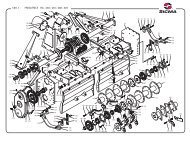
Multi Clamp Grader Blades<br />
The Kanga Multi Clamp Grader Blades use a series of removable Locking Dogs Clamps (DOGS). These clamps can be<br />
very hard to adjust the first couple of time until they wear in and you may need to use a hammer to fit or remove them.<br />
The blade should come with four (4) clamps.<br />
The angle adjustment on the Multi Clamp Grader Blades is controlled by two (2) DOGS. One is stepped and the other<br />
is standard. The standard DOG must always be knocked firmly into a grab made by BOTH the top and bottom plates<br />
while the stepped DOG is knocked on the opposite of the turn table where top and bottom plate DO NOT line up. The<br />
step DOG only acts to stop the top and bottom plates opening up while the standard DOG locks the blade in the position<br />
you have chosen. The reason the blade is set up with the different DOGS is because as the only position where both<br />
DOGS can lock in (ie where two standard DOGS would be effective) is in the “T” position.<br />
The Kanga Multi Clamp Grader Blades can have an angle adjustment between 0° – 45° in 5° increments for grading, etc<br />
or the blade can be reserved and the same amount of adjustment is available for backfilling ditches or trenches.<br />
To adjust the angle of your grader blade raise the implement 50 – 100mm off the ground. Any time that you have raised<br />
the implement to adjust either off set, tilt or angle, please ensure that the tractor is on level ground and that the<br />
implement is level so that the blade cannot swing around under its own weight. Knock off the DOGS and adjust the<br />
angle of the blade to the desired setting, then once in position knock the DOGS firmly into position.<br />
The tilt and offset functions are adjusted the same way as the angle function although they are only require one (1) DOG<br />
to secure the required setting. Both can be adjusted between 0° – 45° in 5°increments. It may not be possible to tilt and<br />
angle the 2.4m blade through the full range of adjustments and still be able to raise the blade enough to clear the ground.<br />
Blade should allows be reserved for backfilling ditches or trenches. Both models of Multi Clamps have the holes<br />
already in place to fit the optional heavy-duty depth wheel kit with a solid wheel.<br />
IMPORTANT<br />
• When using the optional Depth Wheel, you must raise the implement and the wheels off the ground before<br />
operating in reverse.<br />
• Vibration tends to loosen bolts during operation. All hardware should be checked regularly. It is good<br />
practice to check implement before each operation to ensure all hardware is secure.<br />
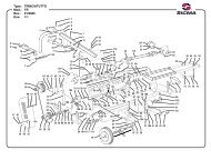
Manual H Range Grader Blades<br />
The Kanga Manual H Range Grader Blades use a series of Locking Bars and Ratchet Racks with lock nuts to adjust<br />
operating positions.<br />
Any time that you have raised the implement to adjust either off set, tilt or angle, please ensure that the tractor is on level<br />
ground and that the implement is level so that the blade cannot swing around under its own weight.<br />
The Kanga Manual H Range Grader Blades can have an angle adjustment between 0° – 45° for grading, etc or the blade<br />
can be reserved and the same amount of adjustment is available for backfilling ditches or trenches. Always ensure blade<br />
is reserved for backfilling ditches or trenches.<br />
To adjust the angle of your grader blade raise the implement 50 – 100mm off the ground. Using the ratchet jack adjust<br />
the angle of the blade to the desired setting, then once in position firmly tighten lock nut on ratchet jack. The tilt<br />
function is adjusted the same way as the angle function and can be adjusted between 0° – 30.°<br />
The Offset adjustment is via a Locking Bar with a pin. Raise the implement 50 – 100mm off the ground and remove the<br />
lynch pin that secures the pin. Remove pin and adjust the blade to the desired offset position between 0° – 36 ° then<br />
replace pin and secure with lynch pin.<br />
13
H / XH Range Hydraulic Grader Blades<br />
The blade maybe angled 30° left or right or to any position in between by using the hydraulic remote controls from the<br />
tractor seat. To angle the blade raise it 50 – 100mm above the ground using the tractors hydraulic lower linkage arms<br />
then activate the ram to the desired position.<br />
The blade is reversible without removing it from the tractor. To reverse the blade, detach one end of the hydraulic ram<br />
and swing the ram out of the way. Raise the Grader Blade off the ground and rotate it anti-clockwise to the desired<br />
position and replace the Hydraulic Rams securing them with the pins.<br />
NT – In some situations it may be necessary to offset the blade to the right and tip up one end of the blade to rotate it.<br />
The tilt ram is used to tilt the blade up or down 30° or any position in between using the tractors hydraulic remote<br />
controls. NT – In some situations it may not be possible to raise the blade high enough to clear the ground. In this case<br />
less tilt will have to be used.<br />
The Offset Ram rotates the headstock 20° left or right or any position in between using the tractors hydraulic remote<br />
controls. To offset the Grader Blade using the ram follow the same process as when angling the blade.<br />
The H & XH Range Grader Blades are available with an optional manual or hydraulic heavy-duty depth wheel kit with<br />
a solid wheel.<br />
IMPORTANT<br />
• When using the optional Depth Wheel, you must raise the implement and the wheels off the ground before<br />
operating in reverse.<br />
• Vibration tends to loosen bolts during operation. All hardware should be checked regularly. It is good<br />
practice to check implement before each operation to ensure all hardware is secure.<br />
14
OPERATING TIPS<br />
• Know your controls and how to stop quickly in an emergency.<br />
• Operators must be instructed in and be capable of the safe operation of the equipment and all controls. Do<br />
not allow anyone to operate this equipment without proper instruction.<br />
• Do not allow children or untrained persons to operate equipment.<br />
• Check that all hardware is tight and properly installed.<br />
• Always wear relatively tight fitted clothing to avoid entanglement in moving parts. Wear heavy-duty,<br />
rough-soled boots and protective equipment for eyes, hair, hands, hearing and head.<br />
• Ensure implement is properly attached, adjusted and in a good condition so that it can be operate safely.<br />
• A minimum 20% of tractor and equipment weight must be on the tractor’s front wheels with implement in<br />
the transport position. Without this weight, tractor could tip over causing personal injury or death. The<br />
weight maybe attained with a loader, front wheel weights, and ballast in the tires or front tractor weights.<br />
When attaining the minimum 20% weight on the front wheels, you must not exceed the ROPS max<br />
ballasted mass certificate. Weight the tractor and implement. Do not estimate.<br />
• Watch for hidden hazards on the terrain during operation and avoid any hazards or object that could cause<br />
injury or damage.<br />
• Inspect operating area. Remove where possible any stones, branches or foreign objects that may cause<br />
injury or damage and look for areas that maybe hazardous to the stability of the tractor.<br />
• Look down and to the rear and make sure area is clear and safe before operating in reverse.<br />
• Do not operate on steep slopes. If in doubt set rear axles wider for moderate slopes.<br />
• Do not stop, start or change directions suddenly on slopes’, working up and down is preferred.<br />
• Use extreme care and reduce ground speed on slopes and rough terrain.<br />
• Stop implement, then tractor, immediately upon striking an obstruction. Turn off engine, remove key,<br />
inspect and repair any damage before resuming operations. Always block implement when inspecting.<br />
• Before commencing any adjustment, maintenance, or cleaning. Always switch off the tractor engine, remove<br />
key and wait until all moving parts have come to a complete stop, then ensure the machine is on the ground<br />
or on a robust secure support.<br />
• Keep hands and body away from pressurized lines. Use paper or cardboard, not hands or other body parts<br />
to check for leaks. Wear safety goggles. Hydraulic fluid (oil) under pressure can easily penetrate the skin<br />
and will cause serious injury or death.<br />
• Make sure that all operating and service personnel know that if hydraulic fluid (oil) penetrates the skin, it<br />
must be surgically removed as soon as possible by a doctor familiar with this form of injury or gangrene,<br />
serious injury or death will result. CONTACT A PHYSICAN IMMEDIATELY IF FLUID ENTERS SKIN<br />
OR EYES. DO NOT DELAY.<br />
Tips…<br />
a) Always secure all locking bars, ratchet jacks and/or hydraulic rams with safety pins supplied.<br />
b) Do not operate without all safety pins fitted. Failure to do so may result in accidents and/or damage.<br />
c) Before changing tilt, offset or angle positions always ensure grader blade is raised and not under load.<br />
d) Look down and to the rear and make sure area is clear before operating in reverse.<br />
e) Do not operate on steep slopes.<br />
f) Do not stop, start or change directions suddenly on slopes.<br />
g) Use extreme care and reduce ground speed on slopes and rough terrain.<br />
h) Pass diagonally through sharp dips and avoid sharp drops.<br />
i) Always watch for objects and remember that only a small area maybe visible and the bulk of the object maybe<br />
hidden under the ground. Hitting the unmovable object can cause damage to both implement and tractor.<br />
j) When grading take into consideration the length of the pass and try and allow for the volume of material you<br />
will be dealing with at the end of that pass.<br />
k) Your grader blade will always be at its most vulnerable when set at the maximum adjustment available.<br />
Always ensure that the primary pass of any heavy work is done with your Blade as close to it original “T”<br />
formation as possible.<br />
l) Using a grader blade for the first time can be tricky. We suggest you take the time to practice before operating<br />
in areas, that if damage, could be costly to repair.<br />
15
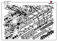
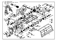
In many situations the H/XH Range of Manual/Hydraulic Grader Blades will come assembled. If not, assembly of this<br />
implement is the responsibility of the KANGA FARM EQUIPMENT dealer. It should be delivered to the new owner<br />
completely assembled, lubricated and adjusted for normal conditions.<br />
To attach the headstock and mould board slide the threaded shaft on the grader blade headstock through the hole in the<br />
mould board turntable. Attach the large nyloc nut and spacer/flat washer and tighten as tight as possible.<br />
The Hydraulic Rams or Ratchet Jacks are fastened into place using the pin and clips supplied. In many case there will<br />
be a top and bottom clip that need to be securely fastened to hold the pin in place.<br />
When attaching the Ram/Ratchet, placement is vital. The longest one is used on the very back of the implement to<br />
control blade angle. The shortest Ram/Ratchet is the unit mounted vertically to control the tilt of the blade and the<br />
middle sized Ram/Ratchet controls the offset.<br />
In the case of Hydraulic Rams there will be a small ram and two large rams. One, if not both the rams will have<br />
restrictors inside them to limit the amount they can move. Remember that due to the Hydraulic Rams available it is<br />
necessary to limit the length of the stroke so the Ram does not over extent. Depending on the tractor it may still be<br />
possible to over extent any one of the rams to a point where they will fowl. This may bend either the implement or the<br />
ram itself. In severe cases the ram can snap or shatter. Always check the range of movement and make necessary<br />
changes to prevent injury or damage.<br />
Complete dealer checklist when assembly is complete.<br />
18
Agricultural Machinery Product OHS Compliance Form<br />
We,<br />
Of,<br />
Gavhall Pty Ltd t/as Kanga <strong>Farm</strong> Equipment<br />
16 Cahill Street<br />
Dandenong, Victoria, <strong>Australia</strong>, 3175<br />
Telephone: 03-9706-5166<br />
Fax: 03-9706-5050<br />
Confirm that the following machine(s)<br />
Kanga Mini Range Grader Blades<br />
Kanga S Range Grader Blades<br />
Kanga M Range Grader Blades<br />
Kanga Multi Clamp Grader Blades<br />
Kanga H Range Grader Blades<br />
Kanga XH Range Grader Blades<br />
have had a hazard identification, risk assessment and risk control procedure carried out on a representative<br />
model of the aforementioned product(s) in accordance with the Occupational Health and Safety<br />
requirements of all states and territories of <strong>Australia</strong> and where found necessary the appropriate risk control<br />
measures have been incorporated in the product specifications.<br />
The Operators Manual contains the necessary Health and Safety information and safety warnings decals<br />
are applied to the product where necessary.<br />
Product Description: Grader Blades<br />
Model Number(s): XH Range – Product Code(s) 47000, 47200<br />
H Range – Product Code(s) 47300, 47350, 47400, 47450<br />
Multi Clamp – Product Code(s) 40000, 41000<br />
M Range – Product Code(s) 43000<br />
S Range – Product Code(s) 44000<br />
Mini Range – Product Code(s) 45000<br />
Name: Bruce J Alcott Date: 01 / 10 / 2003<br />
Position Managing Director Reviewed: 15 / 06 / 2004<br />
Details of the unit assessed for the purpose of compliance<br />
Model # Size Serial # Date of Inspection Location<br />
Mini Range 1.2m 720904 16 / 09 / 2003 16 Cahill St, Dandenong<br />
S Range 1.2m 840904 16 / 09 / 2003 16 Cahill St, Dandenong<br />
M Range 1.8m 510904 16 / 09 / 2003 16 Cahill St, Dandenong<br />
Multi Clamp 2.4m 460904 16 / 09 / 2003 16 Cahill St, Dandenong<br />
H Range Manual 1.8m 150204 04 / 02 / 2004 16 Cahill St, Dandenong<br />
H Range Hydraulic 2.4m 820304 29 / 03 / 2004 16 Cahill St, Dandenong<br />
XH Range Hydraulic 3.0m 860604 10 / 06 / 2004 16 Cahill St, Dandenong<br />
19
PRE-DELIVERY CHECKLIST<br />
(Dealers Responsibility)<br />
Inspect implement thoroughly after assembly to be certain it is set up properly before delivering it to the customer. The<br />
following checklist is a reminder of points to inspect. Check off each item as it is found satisfactory either before or<br />
after corrections or services performed.<br />
NT: Kanga Hydraulic Grader Blades are a generic design to suit a wide range of tractors. Due to the Hydraulic<br />
Rams available it is necessary to limit the length of the stroke so the Ram does not over extent. Depending on the<br />
tractor it may still be possible to over extent any one of the rams to a point where they will fowl. This may bend either<br />
the implement or the ram itself. In severe cases the ram can snap or shatter.<br />
□<br />
□<br />
□<br />
□<br />
□<br />
□<br />
□<br />
□<br />
□<br />
□<br />
□<br />
□<br />
□<br />
□<br />
□<br />
□<br />
Check the stroke range/stroke of ALL rams and make the necessary adjustments to ensure the implement is safe.<br />
When checking the stroke range, do so slowly making regular observations for clearance.<br />
Check all bolts to be sure that they are tight<br />
Check all safety decals are installed and in good condition.<br />
Properly attach implement to tractor and make all necessary adjustments.<br />
Check and grease all lubrication points.<br />
Show customer how to make adjustments. Describe the options available for the implement and explain its<br />
purpose and how it operates.<br />
Explain the importance of lubrication to the customer and point out all the lubrication points on the implement.<br />
Point out the safety decals and explain the importance of safe operating procedures.<br />
Ensure the stability of the tractor has not been compromised with the implement the customer has purchased.<br />
Remember a minimum 20% of the tractor and implement gross weight must be on the front wheels of the tractor.<br />
If you are adding weight to the tractor to attain the 20%, you must not exceed the ROPS weight certificate. Weight<br />
tractor and implement. Do not estimate.<br />
Give Operators Manual to the customer and recommend that customer become familiar with all sections, especially<br />
the safety and safe operating procedures. Point out these sections in the manual to the customer.<br />
Ensure the customer understands that all operators should also read the manual in full and understand the safety and<br />
safe operating procedures.<br />
Explain to the customer that when transporting the implement on roads or highways, day or night, safety devices<br />
should be used to provide adequate warning to operators of other vehicles. Also explain the operator must ensure<br />
that the tractor and implement complies with current State and Federal laws and must strictly adhere to all road<br />
traffic regulations in force in his/her particular state.<br />
Explain the potential crushing hazards of going underneath raised equipment. Instruct customer that service work<br />
does not require going underneath the implement and never to do so.<br />
Show the customer the safe, proper procedures to be used when mounting, dismounting and storing equipment.<br />
Instruct the customer that they MUST carry out a Risk Assessment and/or HazCheck for the implement and the<br />
operating conditions..<br />
Ensure the customer has signed the WARRANTY REGISTRATION & INSTALLATION FORM and a copy<br />
has been returned to Kanga <strong>Farm</strong> Equipment, 16 Cahill Street, Dandenong, Victoria, 3175.<br />
Please tick each box after completion.<br />
Name of person who carried out Pre-delivery: ______________________ Signature: ___________________<br />
Dealership Name: ________________________ Location carried out: _______________________________<br />
Date:<br />
_ _ / _ _ / _ _ _ _<br />
Top copy (manufacture) Middle Copy (dealer) Last page (purchaser)<br />
20
WARRANTY REGISTRATION & INSTALLATION FORM<br />
Owners Name: _ _ _ _ _ _ _ _ _ _ _ _ _ _ _ _ _ _ _ _ _ _ _ _ _ _ _ _ _ _ _ _ _ _ _ _ _ _ _ _ _ _ _ _ _ _ _ _ _ _ _ _ _ _ _ _<br />
Town: _ _ _ _ _ _ _ _ _ _ _ _ _ _ _ _ _ _ _ _ _ _ _ _ _ _ State: _ _ _ _ _ _ _ _ _ _ _ _ P/Code: _ _ _ _<br />
Model: □ Mini Range (adjustable) □ S Range □ M Range □ Multi Clamp<br />
□ H Range (Manual) □ H Range (Hydraulic) □ XH Range<br />
Size: □ 1200mm □ 1800mm □ 2400mm □ 3000mm<br />
Serial Number: _ _ _ _ _ _ _ _ _ _ _<br />
Month of Manufacture: □ Jan □ Feb □ Mar □ Apr □ May □ Jun □ Jul □ Aug □ Sept □ Oct □ Nov □ Dec<br />
Year of Manufacture: __ __ __ __<br />
Date Purchased: _ _ / _ _ / _ _ _ _<br />
Intended areas of use: □ Paddocks Only □ Close to Sheds & Buildings □ Near Roads<br />
Contracting, please specify: _ _ _ _ _ _ _ _ _ _ _ _ _ _ _ _ _ _ _ _ _ _ _ _ _ _ _ _ _ _ _ _ _ _ _ _ _ _<br />
Other, please specify: _ _ _ _ _ _ _ _ _ _ _ _ _ _ _ _ _ _ _ _ _ _ _ _ _ _ _ _ _ _ _ _ _ _ _ _ _ _ _ _ _ _ _ _ _ _ _ _ _ _<br />
I have been fully instructed in the operation of this unit in the actual working conditions that I intended to operate and I am satisfied<br />
that I can use it safely. I acknowledge that I have been fully instructed in the care, maintenance, lubrication and that Kanga Grader<br />
Blades have been designed for use in agricultural applications away from people, animals, roads and property. I understand that there<br />
are Federal and State Laws as well as OH&S Standard that dictate how I can operate should I wish to operate along roads or in any<br />
populated areas and that it is my responsibility to know and adhere to those laws. I have received a copy of the operating manual and<br />
the dealer has instructed me to read the manual in full and carry out my own Risk Assessment before commencing any operations.<br />
□<br />
□<br />
□<br />
□<br />
□<br />
□<br />
□<br />
□<br />
□<br />
_ _ _ _ _ _ _ _ _ _ _ _ _ _ _ _ _ _ _ / _ _ / _ _ _ _<br />
O w n e r’ s S i g n a t u r e.<br />
D a t e<br />
FINAL ASSEMBLY – Checked all hardware to ensure it is firmly tightened as outlined in the Operators<br />
Manual. Customer has been instructed on how to make regular checks and tighten ALL hardware.<br />
LUBRICATION – The implement has been lubricated and checked and the customer has been instructed on<br />
how to check and lubricate implement.<br />
GREASING – All working parts of the machine have been greased. We have instructed the customer on<br />
how/when to re-grease the implement.<br />
IMPLEMEMNT & TRACTOR COMPATIBILITY – Check implement and Tractor compatibility.<br />
Ensure that a minimum 20% of tractor and equipment weight is on the tractor’s front wheels with implement<br />
in transport position.<br />
OPERATION PROCEDURES – Instruct the operator on correct procedures and techniques for the type of<br />
work they have indicated they intend to carry out. General safe operating procedures can be found in the<br />
Operators Manual. Advise customer to carry out a risk assessment and hazard identification of the property<br />
and alert the customer to the type of potential dangers they should be looking to avoid.<br />
DANGERS – Instruct customer on the potential dangers of operating the implement. Outline the dangers<br />
associated with hydraulic fluid, debris, rotating parts and ensure the customer knows that information about<br />
safe operating procedures and regular maintenance can be found in the Operators Manual.<br />
OWNERS/OPERATORS MANUAL – Check that the implement has a booklet supplied. Emphasize the<br />
importance of reading the Manual. Note, manuals can be down loaded from www.farmimplements.com.au<br />
MAINTENANCE – Explain to the operator the requirements and repercussions of regular maintenance.<br />
RISK ASSESSMENT – Ensure you instruct the customer to complete a HazCheck for the implement and<br />
their operating conditions.<br />
Please tick each box after completion.<br />
Dealership Name: _ _ _ _ _ _ _ _ _ _ _ _ _ _ _ _ _ _ _ _ _ Pre-delivered By: _ _ _ _ _ _ _ _ _ _ _ _ _ _ _ _ _ _ _ _<br />
Salesperson’s Name: _ _ _ _ _ _ _ _ _ _ _ _ _ _ _ _ _ _ _ _ Salesperson’s Signature: _ _ _ _ _ _ _ _ _ _ _ _ _ _ _ _ _<br />
Top copy (manufacture) Middle Copy (dealer) Last page (purchaser)<br />
21