PTO Shaft Shortening & Maintenance - Farm Implements Australia
PTO Shaft Shortening & Maintenance - Farm Implements Australia
PTO Shaft Shortening & Maintenance - Farm Implements Australia

You also want an ePaper? Increase the reach of your titles
YUMPU automatically turns print PDFs into web optimized ePapers that Google loves.
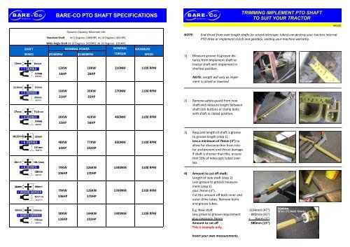
BARE-CO <strong>PTO</strong> SHAFT SPECIFICATIONS<br />
Page 7<br />
TRIMMING IMPLEMENT <strong>PTO</strong> SHAFT<br />
TO SUIT YOUR TRACTOR<br />
INS 142<br />
Dynamic Capacity Minimum Life.<br />
Standard <strong>Shaft</strong> At 5 Degrees 1000HRS. At 10 Degrees 100 HRS.<br />
Wide Angle <strong>Shaft</strong> At 10 Degrees 1000HRS. At 18 Degrees 100 HRS.<br />
SHAFT NOMINAL POWER NOMINAL MAXIMUM<br />
SERIES @540RPM @1000RPM TORQUE SPEED<br />
12KW 19KW 210NM 1100 RPM<br />
16HP<br />
26HP<br />
16KW 26KW 270NM 1100 RPM<br />
21HP<br />
35HP<br />
26KW 42KW 460NM 1100 RPM<br />
35HP<br />
56HP<br />
NOTE:<br />
End thrust from over length shafts (or seized telescopic tubes) can destroy your tractors internal<br />
<strong>PTO</strong> drive or implement clutch and gearbox, voiding your machine warranty.<br />
1) Measure groove to groove distance<br />
from implement shaft to<br />
tractor shaft with implement in<br />
shortest position.<br />
NOTE: Length will vary as implement<br />
is raised or lowered<br />
2) Remove safety guard from new<br />
shaft and measure length between<br />
shaft lock buttons or clamp bolts<br />
with shaft in closed position.<br />
48KW 77KW 830NM 1100 RPM<br />
64HP<br />
102HP<br />
79KW 126KW 1390NM 1100 RPM<br />
3) Required length of shaft is groove<br />
to groove length (step 1)<br />
less a minimum of 76mm (3”) to<br />
allow for disconnection from tractor<br />
and prevent end thrust damage.<br />
If shaft is shorter than this, ensure<br />
that 50% of telescopic tubes overlap.<br />
106HP<br />
170HP<br />
79KW 126KW 1390NM 1100 RPM<br />
106HP<br />
170HP<br />
4) Amount to cut off shaft;<br />
Length of new shaft (step 2)<br />
Less groove to groove measurement<br />
(step 1)<br />
plus 76mm (3”).<br />
Cut this amount off both inner and<br />
outer drive tubes. Remove burrs<br />
and grease tubes.<br />
90KW 144KW 1400NM 1100 RPM<br />
120HP<br />
192HP<br />
E.g. New shaft<br />
Less grove to groove requirement<br />
plus clearance 76mm<br />
Amount to cut off<br />
This is example only<br />
1194mm (47”)<br />
- 890mm (35”)<br />
+ 76mm (3”)<br />
380mm (15”)<br />
6<br />
Insert your own measurements.
Page 2<br />
CUTTING SAFETY GUARD TO REQUIRED LENGTH<br />
FAILURE PREVENTION<br />
<strong>Shaft</strong> Operating Angle<br />
Adjust tractor hydraulic control to minimise lift height. High lift and large shaft angle will destroy universal joint.<br />
1<br />
All Bare-Co <strong>PTO</strong> shafts (single universal joint)<br />
Short time running: Maximum angle 25 degrees<br />
Continuous operation: Maximum angle 17 degrees<br />
All Bare-Co Wide Angle <strong>PTO</strong> shafts (double universal joint)<br />
Short time running (or stationary): Maximum angle 80 degrees<br />
Continuous operation: Maximum angle 25 degrees<br />
2<br />
LUBRICATION<br />
Sliding Members<br />
Use high temperature grease similar to HP multi-purpose chassis grease.<br />
Grease sliding members prior to assembly and after every 20 hours of use. For applications with high telescoping<br />
movement grease every 8 hours.<br />
Bare-Co shafts from 8 series upwards are equipped with a grease nipple which can be accessed by releasing<br />
the patent guard to align access hole.<br />
Universal Joints<br />
Grease standard joints every 20 hours or 8 hours for severe conditions. Wide angle joints every 8 hours under<br />
wide angle conditions. Operating standard shafts at greater than 10 degrees angle or wide angle shafts at<br />
greater than 18 degrees angle dramatically reduces cross bearing life and requires more frequent lubrication.<br />
3 4<br />
“B” = “A” – 76mm (3”)<br />
(“B” is 76mm (3”) less than “A”)<br />
IMPORTANT: Grease follows the easiest path through internal<br />
ports to the four cross bearings.<br />
Over heating and poor quality grease baked in one port will<br />
prevent grease reaching that bearing, resulting in failure of individual<br />
cross bearings.<br />
Typical cross failure due to blocked internal grease port<br />
5<br />
6<br />
MOST IMPORTANT!<br />
Fully open guard covers to ensure grease flows to all cross bearings<br />
Greasing through small guard access holes is not good enough!<br />
How to prevent wide angle shaft failures:<br />
1) If 80 degree wide angle shafts are angled at greater than 80 degrees (Jack knifing implement with shaft<br />
stationary or rotating), the centre support ball and socket will break (not covered by warranty). To<br />
avoid over angling , fit turn limiters to your implement draw bar. Correctly fitted turn limiters will contact<br />
tractor tyre prior to over angling.<br />
2) The very large centre disc lubrication cavity must be completely full before any grease transfers from<br />
the cavity to the centre support ball and socket. More than half a cartridge of grease is required to fill<br />
this cavity on initial shaft installation.<br />
3) Wide angle covers should be completely removed to ensure grease flows to the centre support ball<br />
and all eight cross bearings