Working On a SIPs Roof - VELUX
Working On a SIPs Roof - VELUX
Working On a SIPs Roof - VELUX

Create successful ePaper yourself
Turn your PDF publications into a flip-book with our unique Google optimized e-Paper software.
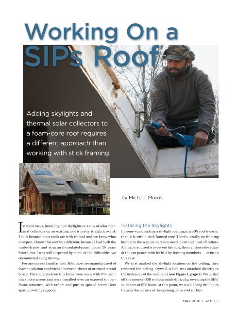
<strong>Working</strong> <strong>On</strong> a<br />
<strong>SIPs</strong> <strong>Roof</strong><br />
Adding skylights and<br />
thermal solar collectors to<br />
a foam-core roof requires<br />
a different approach than<br />
working with stick framing<br />
by Michael Morris<br />
In most cases, installing new skylights or a row of solar thermal<br />
collectors on an existing roof is pretty straightforward.<br />
That’s because most roofs are stick-framed and we know what<br />
to expect. I knew this roof was different, because I had built the<br />
timber-frame and structural-insulated-panel home 20 years<br />
before, but I was still surprised by some of the difficulties we<br />
encountered along the way.<br />
For anyone not familiar with <strong>SIPs</strong>, most are manufactured of<br />
foam insulation sandwiched between sheets of oriented strand<br />
board. The roof panels on this home were made with 9 1 /4-inchthick<br />
polystyrene and were installed over an exposed timberframe<br />
structure, with rafters and purlins spaced several feet<br />
apart providing support.<br />
Installing the Skylights<br />
In some ways, making a skylight opening in a <strong>SIPs</strong> roof is easier<br />
than it is with a stick-framed roof: There’s usually no framing<br />
lumber in the way, so there’s no need to cut and head off rafters.<br />
All that’s required is to cut out the hole, then reinforce the edges<br />
of the cut panels with let-in 2-by framing members — 2x10s in<br />
this case.<br />
We first marked the skylight location on the ceiling, then<br />
removed the ceiling drywall, which was attached directly to<br />
the underside of the roof panel (see Figure 1, page 2). We pulled<br />
off the interior OSB without much difficulty, revealing the <strong>SIPs</strong>’<br />
solid core of EPS foam. At this point, we used a long drill bit to<br />
transfer the corners of the opening to the roof surface.<br />
MAY 2010 l JLC l 1
<strong>Working</strong> <strong>On</strong> a Sips <strong>Roof</strong><br />
Removing the EPS — the stuff disposable coffee cups are<br />
made of — is not as simple as it might seem. The material<br />
resists being cut with sharp-bladed tools, and sawing, slicing,<br />
or chopping it produces a blizzard of foam particles that<br />
are a pain to clean up. A “hot knife” — an electric resistance<br />
wand that resembles a plug-in charcoal lighter — is the<br />
right tool for this job. The wand’s element heats up quickly<br />
and cuts through the foam like a hot knife through butter; it<br />
quickly carved away the thick foam in repeated passes.<br />
A rough opening in a SIP requires the support of solid<br />
wood framing around all edges. After we finished cutting the<br />
opening, the crew used the hot knife to recess the foam along<br />
all four sides to receive the framing members (Figure 2, page<br />
3). The tool shown here is sized to remove foam from the edge<br />
of a nominal 6-inch-thick SIP so that 2x6 framing can be let<br />
in. The adjustable depth gauge rides on the OSB and sets the<br />
depth of the cut according to the thickness of the framing to<br />
be installed. For this job, we set it at 1 1 /2 inches, and made two<br />
passes to accommodate the 2x10 framing we would need for<br />
the 10-inch-thick panel. As we inserted the framing, we used<br />
canned spray foam to fill gaps and adhere the framing, then<br />
nailed it off through the interior and exterior OSB skins.<br />
The rest of the skylight installation was straightforward.<br />
As usual, we flashed the Velux units with the manufacturersupplied<br />
metal flashings.<br />
Figure 1. After laying out the skylights from the interior<br />
and removing the drywall (top), the installer transfers<br />
the location to the roof (center). The bulk of the foam<br />
is removed with a recip saw (above).<br />
Prepping the <strong>Roof</strong> for the Collectors<br />
Because the Velux solar thermal system we were using was<br />
still new to the U.S. market, I first contacted the manufacturer<br />
to make sure we would receive on-site technical support.<br />
I also called the manufacturer of the <strong>SIPs</strong> to discuss the<br />
installation.<br />
The collectors mount directly to the roof deck without<br />
any additional mounting hardware like stand-off brackets<br />
or racks. Because the <strong>SIPs</strong> were attached to timber-frame<br />
rafters spaced several feet apart, I was concerned about<br />
not having solid anchoring points for the collectors. There<br />
was another issue as well: In the two decades since the home<br />
was built, some structural settling had taken place, resulting<br />
in an uneven roof deck (Figure 3, page 3). Although<br />
settling is normal in any wood structure as the framing<br />
dries and gravity sets in, timber frames are somewhat<br />
more prone to it because the heavy beams may be green<br />
when they’re installed and can have a higher moisture content<br />
than dry framing lumber. So even though the <strong>SIPs</strong> were<br />
dry and stable when installed, over time they settled as the<br />
MAY 2010 l JLC l 2
Figure 2. After the opening is made,<br />
the crew uses a “hot knife” (far left)<br />
to create a recess for 2x10 framing<br />
around the edges (left). Above, the<br />
finished skylight well.<br />
A<br />
B<br />
C<br />
D<br />
Figure 3. A vertical ripple in the shingles (A) was caused by a slight displacement in the roof panels’ edges (B).<br />
To make sure the surface was flat before reshingling, the author secured the edges of the panels with washer<br />
screws driven into the framing (C), then added another layer of OSB sheathing over the entire roof (D).<br />
MAY 2010 l JLC l 3
<strong>Working</strong> <strong>On</strong> a Sips <strong>Roof</strong><br />
timbers shrank and settled, causing some of the 12-inch-long<br />
panel spikes securing them to the rafters to loosen. The result<br />
was a noticeable uplift along several panel joints, which telegraphed<br />
through the asphalt shingles and even caused a leak in<br />
one spot.<br />
Prompted by my concerns, the panel manufacturer at first<br />
suggested adding cleats on the underside of the roof deck as<br />
anchoring reinforcement, but Velux assured me that its system<br />
did not require fastening to roof framing. The 4 1 /2-foot-by-<br />
6-foot collectors, which have a very low profile and weigh just<br />
130 pounds apiece, are designed to lie flat against the roof,<br />
directly on the sheathing. An integral perimeter flange, like the<br />
nailing flange on windows, attaches directly to the roof sheathing.<br />
The flashing process is similar to that for skylights.<br />
As for flattening the roof, the parties agreed that I should<br />
strip the entire roof deck, refasten the <strong>SIPs</strong> as needed, then add<br />
a second layer of 1 /2-inch sheathing before installing the collectors<br />
and new shingles. For securing the panels, we used 12-inch<br />
hardened T-30 Torx-drive panel screws with 2-inch fender washers.<br />
The screws did a good job of pulling each of the uplifted<br />
edges flat. Between this and the new sheathing that overlapped<br />
the existing seams, we now had a uniform, double-thick roof<br />
deck that we could attach the collectors to.<br />
Installing the Collectors<br />
With the various preliminary complications behind us, we turned<br />
to the job of installing the collectors. Here too, dealing with a <strong>SIPs</strong><br />
roof required some innovation and adaptation on our part.<br />
In order to put the collectors in the optimum location, we<br />
would have to route the supply and return fluid lines — flexible<br />
stainless steel coil tubes with 2-inch-thick insulating jackets —<br />
through the roof directly above the interior cathedral ceilings.<br />
With no rafter bays to work in — but with a small storage loft reasonably<br />
close to where both lines would come through the roof<br />
deck — our best option was to tunnel through the <strong>SIPs</strong>’ foam<br />
and pull the lines into the loft. From there, we had easy access<br />
to a double-stud-width plumbing wall and closet below, and a<br />
straight run from that point to the basement water tank.<br />
The three collectors were mounted in series across the top of<br />
the roof, about a foot below the ridge. The inlet plumbing line<br />
would be attached at the bottom left corner of the first collector,<br />
and the outlet line at the bottom right corner of the third collector.<br />
Short prefabricated tube connectors linked each panel to its<br />
neighbor at adjacent bottom corners.<br />
We first cut a 6-inch-by-6-inch pocket in the roof deck below<br />
the inlet attachment point and scooped out some of the foam to<br />
create a cavity (Figure 4). Then, on the inside, we cut a similar<br />
A<br />
C<br />
B<br />
D<br />
Figure 4. The solar<br />
installer uses a recip<br />
saw to cut one of<br />
the penetrations<br />
needed for the fluid<br />
pipe loop between<br />
the collectors and<br />
the utility room (A).<br />
Inside, a worker<br />
makes a hole in the<br />
ceiling several feet<br />
away, then scoops<br />
out a recess with a<br />
hot knife (B). <strong>Working</strong><br />
from this access<br />
point, a worker uses<br />
a long drill bit to<br />
locate the penetration<br />
and create a<br />
tunnel to pull the<br />
pipe through (C).<br />
Snaking the pipes<br />
through the panels to<br />
the basement proved<br />
to be tricky (D).<br />
MAY 2010 l JLC l 4
A<br />
B<br />
Figure 5. The<br />
Velux solar collectors<br />
were simply<br />
screwed directly to<br />
the roof sheathing<br />
(A). After running<br />
the fluid lines to<br />
the utility room (B),<br />
the installers made<br />
connections at the<br />
manifold assembly,<br />
which includes a<br />
pump, gauges,<br />
and controls (C).<br />
A pressure tank<br />
and insulated storage<br />
tank complete<br />
the installation (D).<br />
C<br />
D<br />
pocket several feet away in the ceiling of the storage loft, where<br />
it wouldn’t be seen. This gave us an access point from which we<br />
could use a 5-foot 1 1 /4-inch flexible auger bit to tunnel directly to<br />
the roof opening. By measuring carefully, we were able to quickly<br />
drill a channel into the roof pocket several feet below and a few<br />
feet to the left of our loft access hole.<br />
Encouraged by our success, we repeated the process for the<br />
outlet attachment point. This time, however, we found the route<br />
partially blocked by rows of spikes and panel screws fastening<br />
two of the roof <strong>SIPs</strong> to a timber rafter. Adding to the difficulty, the<br />
distance was considerably longer — more than 8 feet from hole<br />
to hole — so we had to add a 4-foot extension to the 5-foot auger<br />
bit. It took numerous attempts to guide the now-wobbly flexible<br />
bit through a forest of obstructions to a target we couldn’t see.<br />
We eventually succeeded, but not before removing considerable<br />
amounts of EPS.<br />
<strong>On</strong>ce we had access from both collector ports to the attic, the<br />
solar installation part of the job was fairly routine (Figure 5). The<br />
Velux installation guidelines recommend using unbroken runs<br />
of tubing from the collectors to the hot-water tank, so, after measuring<br />
carefully, the installers fished the collector lines all the<br />
way to the utility room. We filled all the roof pockets with canned<br />
spray foam, patched the sheathing, and installed a self-sticking<br />
membrane on the deck around the collectors before the Velux<br />
flashing kits were installed.<br />
<strong>Working</strong> around the structural insulated panels added about<br />
two days to the solar collector installation. It’s also possible we<br />
created some cold spots in the roof where the foam was removed<br />
for the fluid lines, since we couldn’t repack the areas that were<br />
out of reach. I’m generally satisfied with the job, and glad to have<br />
added the panel screws, which are better than panel spikes at<br />
resisting uplift. The Velux solar thermal system itself seems welldesigned<br />
and simple to install.<br />
Michael Morris, a former builder and remodeling contractor,<br />
now writes about construction from his home in Ossining, N.Y.<br />
MAY 2010 l JLC l 5