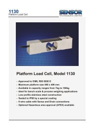
Photo 100 x 145 mm - LOAD CELLS .com
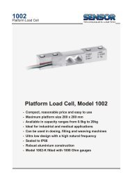
Photo 100 x 145 mm - LOAD CELLS .com
Photo 100 x 145 mm - LOAD CELLS .com

You also want an ePaper? Increase the reach of your titles
YUMPU automatically turns print PDFs into web optimized ePapers that Google loves.
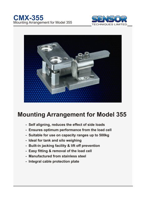
CMX-355<br />
Mounting Arrangement for Model 355<br />
<strong>Photo</strong><br />
<strong>100</strong> x <strong>145</strong> <strong>mm</strong><br />
Mounting Arrangement for Model 355<br />
- Self aligning, reduces the effect of side loads<br />
- Ensures optimum performance from the load cell<br />
- Suitable for use on capacity ranges up to 500kg<br />
- Ideal for tank and silo weighing<br />
- Built-in jacking facility & lift off prevention<br />
- Easy fitting & removal of the load cell<br />
- Manufactured from stainless steel<br />
- Integral cable protection plate
Technical Data<br />
CMX-355<br />
TAKE CARE :<br />
Service position 86<br />
Weighing position 80<br />
Load Pillar<br />
56<br />
Mounting<br />
threads<br />
M12-1.75<br />
(2 places)<br />
11<br />
15<br />
Cable Protection Plate<br />
Model 355<br />
Spacer<br />
15<br />
Mounting<br />
holes 11<br />
(2 places)<br />
70<br />
<strong>100</strong><br />
THE METAL BELLOWS ON THE<br />
355 <strong>LOAD</strong> CELL CAN EASILY BE<br />
DAMAGED. THIS WILL AFFECT<br />
WEIGHING ACCURACY.<br />
Fitting Instructions<br />
1/ Ensure that the mounting<br />
arrangement is in the service<br />
position.<br />
2/ Secure the mounting<br />
arrangement firmly to the<br />
installation. Make sure that all<br />
parts are level and aligned<br />
correctly.<br />
3/ Remove the load cell mounting<br />
bolts and cable protection plate.<br />
Fit the load pillar into the ‘live’<br />
end of the load cell and place<br />
the loadcell <strong>com</strong>plete with load<br />
pillar into mounting<br />
arrangement. Secure the load<br />
cell with the bolts provided.<br />
(finger tight)<br />
4/ The top of the load pillar is<br />
rectangular in shape. This<br />
allows you to orientate the load<br />
pillar to allow for expansion in<br />
the installation (left to right or<br />
front to back). Align as<br />
appropriate.<br />
5/ Before lowering the load onto<br />
the load cell, ensure that the<br />
load pillar arrangement is<br />
engaging correctly. Slowly and<br />
evenly, bring all the mounting<br />
arrangements into their weighing<br />
positions.<br />
6/ Tighten the load cell mounting<br />
bolts to a reco<strong>mm</strong>ended torque<br />
of 22Nm (16 lbs.ft.)<br />
7/ For multi-cell applications,it is<br />
important to ensure that each<br />
loading point is evenly loaded.<br />
If this is not the case, shims can<br />
be placed between the mounting<br />
arrangement and the installation<br />
to correct this.<br />
42<br />
118<br />
132<br />
All Dimensions in <strong>mm</strong><br />
Specifications are subject to change without prior notice<br />
DSCMX355LP-2, 7/97<br />
Tel. +44 (0)1446 771185 Fax +44 (0)1446 771186<br />
Precision Load cells<br />
Accessories and Mountings<br />
Measuring Instruments and Systems