PKZ 0 Motor Protectors Technical Data
PKZ 0 Motor Protectors Technical Data
PKZ 0 Motor Protectors Technical Data

Create successful ePaper yourself
Turn your PDF publications into a flip-book with our unique Google optimized e-Paper software.
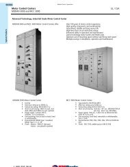
Manual <strong>Motor</strong> <strong>Protectors</strong>,<br />
<strong>Motor</strong> Protector Combinations<br />
08/060<br />
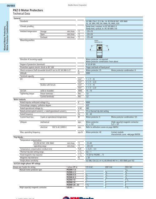
<strong>PKZ</strong> 0 <strong>Motor</strong> <strong>Protectors</strong><br />
<strong>Technical</strong> <strong>Data</strong><br />
General<br />
Standards UL 508, CSA C 22.2 No. 14, IEC/EN 60 947, VDE 0660<br />
GL, LR, DNV, PRS, BV, RINA, RS, MEEI, EZU<br />
Climatic proofing Damp heat, constant, to IEC 60 068-2-3<br />
Damp heat, cyclical, to IEC 60 068-2-30<br />
Ambient temperature Storage min./max. °C −25/+70<br />
Open min./max. °C −25/+55<br />
Enclosed min./max. °C −25/+40<br />
Mounting position<br />
Moeller Electric Corporation<br />
Direction of incoming supply <strong>Motor</strong> protector: as required<br />
<strong>Motor</strong> protector combination: from above<br />
Degree of protection (terminals) IP 20 (IP 00)<br />
Protection against electric shock to IEC 536 Finger and back-of-hand proof<br />
Shock resistance (half-sinusoidal shock10 ms) to IEC 60 068-2-27 g <strong>Motor</strong> protector: 25 <strong>Motor</strong> protector combination: 8<br />
Altitude m 2000<br />
Terminal capacity<br />
IEC solid mm 2 1 x (1 – 6)<br />
mm 2 2 x (1 – 2,5)<br />
flexible with ferrule mm 2 1 x (1 – 4)<br />
mm 2 2 x (1 – 2,5)<br />
UL/CSA solid or stranded AWG 14 – 10<br />
Tightening torque Power terminals Nm 1,8<br />
Control terminals Nm 1,0<br />
Main contacts<br />
Rated impulse withstand voltage Uimp V 6000<br />
Overvoltage category / pollution degree III/3<br />
Rated operational voltage Ue V AC 690<br />
Rated uninterrupted current Iu = rated operational current le A 25 or thermal trip dial setting<br />
Rated frequency Hz 40 – 60<br />
Current heat loss 3-pole at operational temperature W <strong>Motor</strong> protector: 6 <strong>Motor</strong> protector combination: 9,5<br />
Lifespan mechanical ops. <strong>Motor</strong> protector:<br />
0,1 x 10 6<br />
electrical 100 % AC-3/400 V ops. Refer to utilization curves on page 08/052<br />
(High capacity) magnetic contactor:<br />
5,0 x 10 6<br />
Max. operating frequency ops./h <strong>Motor</strong> protector: 40 Contact module<br />
characteristic curve a page 08/058<br />
Trip blocks<br />
Temperature compensation<br />
IEC/EN 60 947, VDE 0660 min./max. °C −5/+40<br />
operating range min./max. °C −25/+55<br />
Temperature compensation residual error %/K F 0,25 − 0,4<br />
Thermal trip dial setting range x lu 0,6 – 1<br />
Fixed magnetic trip response x lu 14 (20 for <strong>PKZ</strong>M0-...-T)<br />
Magnetic trip tolerance % g 20<br />
Single phase sensitivity UL 508, CSA 22.2 # 14, IEC/EN 60 947-4-1, VDE 0660 part 102<br />
UL/CSA single-phase HP ratings<br />
90°<br />
<strong>PKZ</strong>M0<br />
<strong>PKZ</strong>M0/S(E) 00<br />
always use 3 poles for wiring 1 phase HP at 115 V AC 200 V AC 230 V AC<br />
Manual motor protector type <strong>PKZ</strong>M0-1.6 - - 1 /10<br />
<strong>PKZ</strong>M0-2.5 - 1 /8<br />
1 /6<br />
<strong>PKZ</strong>M0-4.0<br />
1/8<br />
1/4<br />
1/3<br />
<strong>PKZ</strong>M0-6.3<br />
1 /4<br />
1 /2<br />
1 /2<br />
<strong>PKZ</strong>M0-10 1 /2 1 1 1 /2<br />
<strong>PKZ</strong>M0-16 1 2 2<br />
<strong>PKZ</strong>M0-20...25 1 1 /2 3 3<br />
(High capacity) magnetic contactor S(E)00-... 1 /2 1 1 1 /2<br />
1-866-595-9616<br />
1-630-595-9515 Go to: http://www.klocknermoeller.com<br />
90°
<strong>PKZ</strong>M0 <strong>Motor</strong> <strong>Protectors</strong><br />
<strong>Technical</strong> <strong>Data</strong><br />
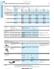
System <strong>PKZ</strong>0 short-circuit ratings per IEC/EN 60 947 standards for international applications<br />
Iu = Maximum continuous current rating of each device<br />
Iq = Conditional short-circuit current rating (per IEC/EN 60 947-2, relevant for motor starters and motor starter combinations)<br />
Icu = Ultimate braking capacity (per IEC/EN 60 947-2, relevant for circuit breakers)<br />
Ics = Continuity of service breaking capacity (per IEC/EN 60 947-2, relevant for circuit breakers)<br />
All kA ratings are RMS Sym. values<br />
N<br />
A<br />
Indicates self-protected range (100 kA)<br />
Not necessary. Backup protection is not required since device is operating within its self-protected range<br />
On request<br />
230 V 400 V 440 V 500 V 690 V<br />
Iu Iq Icu Ics Iq Icu Ics Iq Icu Ics Iq Icu Ics Iq Icu Ics<br />
A kA kA kA A 1) kA kA kA A 1) kA kA kA A 1) kA kA kA A 1) kA kA kA A 1)<br />
<strong>PKZ</strong>M0 motor protector, coordination types “1” and “2”<br />
0,16 – 1 N N N N N<br />
1,6 N N N N N<br />
2,5 N N N N 5 5 5 50<br />
4 N N N N 3 3 3 50<br />
6,3 N N N 6 6 6 50 3 3 2 50<br />
10 N N 10 10 10 50 6 6 6 50 3 3 2 50<br />
16 16 16 8 50 16 16 8 50 10 10 10 50 6 6 6 50 3 3 2 50<br />
20 16 16 8 50 16 16 8 50 10 10 10 50 6 6 6 50 3 3 2 50<br />
25 16 16 8 50 16 16 8 50 10 10 10 50 6 6 6 50 3 3 2 50<br />
PKM0 motor protector + CL-<strong>PKZ</strong>0 current limiter<br />
0,16 – 1 N N N N 20 N<br />
1,6 N N N N 20 N<br />
2,5 N N N N 20 20 20 N<br />
4 N N N N 20 20 20 N<br />
6,3 N N N 50 50 50 N 20 20 20 N<br />
10 N N N 20 20 20 N 20 20 20 N<br />
16 N N N 20 20 20 N 5 5 2,5 N<br />
20 N N N 10 10 10 N 5 5 2,5 N<br />
25 N N N 10 10 10 N 5 5 2,5 N<br />
PKM0 + CL-<strong>PKZ</strong>0 + upstream CL-<strong>PKZ</strong>0 used as additional backup protection<br />
0,16 – 1 N N N N A N<br />
1,6 N N N N A N<br />
2,5 N N N N 40 40 A N<br />
4 N N N N 40 40 A N<br />
6,3 N N N 40 40 40 N 20 20 A N<br />
10 N N N 40 40 40 N 20 20 A N<br />
16 N N N 40 40 40 N 10 10 A N<br />
20 N N N 20 20 20 N 10 10 A N<br />
25 N N N 20 20 20 N 10 10 A N<br />
<strong>Motor</strong> protector combination <strong>PKZ</strong>M0-.../SE00... (coordination type “1”) and <strong>PKZ</strong>M0-.../S00... (coordination Type “1” and “2”)<br />
0,16 – 1 N N N N N N N N N N N N N N N<br />
1,6 N N N N N N N N N N N N N N N<br />
2,5 N N N N N N N N N N N N 5 N N 50<br />
4 N N N N N N N N N N N N 5 N N 50<br />
6,3 N N N N N N N N N 6 N N 50 3 N N 50<br />
10 N N N N N N N N N 6 N N 50 3 N N 50<br />
Notes<br />
Moeller Electric Corporation<br />
1) Additional backup protection is required whenever the available the short-circuit current exceeds the Iq conditional short-circuit current rating<br />
shown in the table.<br />
The conditional short circuit current rating is then dependent on the short-circuit rating of the fuse<br />
50 A gL/gG Iq = 100 kA<br />
100 A gL/gG Iq = 30 kA<br />
08/061<br />
1-866-595-9616<br />
1-630-595-9515 Go to: http://www.klocknermoeller.com<br />
Manual <strong>Motor</strong> <strong>Protectors</strong>,<br />
<strong>Motor</strong> Protector Combinations
Manual <strong>Motor</strong> <strong>Protectors</strong>,<br />
<strong>Motor</strong> Protector Combinations<br />
08/062<br />
<strong>PKZ</strong> 0 <strong>Motor</strong> <strong>Protectors</strong><br />
<strong>Technical</strong> <strong>Data</strong><br />
(High-capacity) contact module<br />
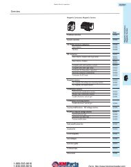
Magnet systems<br />
AC<br />
Operating range Single-voltage coil 50 Hz and Pick-up x Us 0,85 – 1,1<br />
dual-voltage 50 Hz, 60 Hz Drop-out x Us 0,4 – 0,6<br />
Dual-frequency coil Pick-up x Us 0,85 – 1 ,1<br />
...V 50/60 Hz Drop-out x Us 0,25 – 0 ,5<br />
Power consumption Single-voltage coil 50 Hz and Pull-in VA/W 25/22<br />
dual-voltage 50 Hz, 60 Hz Sealing VA/W 4,6/1,3<br />
Dual-frequency coil Pull-in VA/W 30/26<br />
...V 50/60 Hz at 50 Hz Sealing VA/W 5,6/1,6<br />
...V 50/60 Hz at 60 Hz Pull-in VA/W 29/24<br />
Sealing VA/W 3,9/1,1<br />
Operating times at 100 % Us (main contacts)<br />
Closing delay ms 14 – 21<br />
Opening delay ms 8 – 18<br />
DC<br />
Operating range Pick-up x Us 0,85 – 1,1<br />
Power consumption Pull-in = sealing W 2,6<br />
Operating times at 100 % Us (main contacts)<br />
Closing delay ms 26 – 35<br />
Opening delay ms 15 – 20<br />
Duty factor % DF 100<br />
System <strong>PKZ</strong>0 motor protector<br />
IEC kW ratings (AC-3)<br />
AC-3 kW rating at 220 V<br />
230 V<br />
240 V<br />
380 V<br />
400 V<br />
415 V<br />
440 V 500 V 660 V<br />
690 V<br />
kW kW kW kW kW<br />
Manual motor protector type <strong>PKZ</strong>M0-0.16 - - - - 0.06<br />
<strong>PKZ</strong>M0-0.25 - 0.06 0.06 0.06 0.12<br />
<strong>PKZ</strong>M0-0.4 0.06 0.09 0.12 0.12 0.18<br />
<strong>PKZ</strong>M0-0.63 0.09 0.12 0.18 0.25 0.25<br />
<strong>PKZ</strong>M0-1 0.12 0.25 0.25 0.37 0.55<br />
<strong>PKZ</strong>M0-1.6 0.25 0.55 0.55 0.75 1.1<br />
<strong>PKZ</strong>M0-2.5 0.37 0.75 1.1 1.1 1.5<br />
<strong>PKZ</strong>M0-4.0 0.75 1.5 1.5 2.2 3<br />
<strong>PKZ</strong>M0-6.3 1.1 2.2 3 3 4<br />
<strong>PKZ</strong>M0-10 2.2 4 4 4 7.5<br />
<strong>PKZ</strong>M0-16 4 7.5 9 9 12.5<br />
<strong>PKZ</strong>M0-20 5.5 9 11 12.5 15<br />
<strong>PKZ</strong>M0-25 5.5 12.5 12.5 15 22<br />
<strong>Motor</strong> protector and contactor combination <strong>PKZ</strong>M0-0.16/S(E)00... - - - - 0.06<br />
<strong>PKZ</strong>M0-0.25/S(E)00... - 0.06 0.06 0.06 0.12<br />
<strong>PKZ</strong>M0-0.4/S(E)00... 0.06 0.09 0.12 0.12 0.18<br />
<strong>PKZ</strong>M0-0.63/S(E)00... 0.09 0.12 0.18 0.25 0.25<br />
<strong>PKZ</strong>M0-1/S(E)00... 0.12 0.25 0.25 0.37 0.55<br />
<strong>PKZ</strong>M0-1.6/S(E)00... 0.25 0.55 0.55 0.75 1.1<br />
<strong>PKZ</strong>M0-2.5/S(E)00... 0.37 0.75 1.1 1.1 1.5<br />
<strong>PKZ</strong>M0-4.0/S(E)00... 0.75 1.5 1.5 2.2 3<br />
<strong>PKZ</strong>M0-6.3/S(E)00... 1.1 2.2 3 3 4<br />
<strong>PKZ</strong>M0-10/S(E)00... 2.2 4 4 4 -<br />
<strong>PKZ</strong>M0-.../SP, UL/CSA Type E manual self-protected combination controller<br />
Moeller Electric Corporation<br />
Max. continuous current A 16<br />
Max. 3 phase Horsepower rating 200V 3<br />
230V 5<br />
460V 10<br />
575V 10<br />
UL/CSA interrupting rating <strong>PKZ</strong>M0-.../SP, up to 11A: 50kA rms sym @ 480Y/277V<br />
<strong>PKZ</strong>M0-..../SP, up to 16A: 42kA rms sym @ 480Y/277V<br />
1-866-595-9616<br />
1-630-595-9515 Go to: http://www.klocknermoeller.com
<strong>PKZ</strong>0 <strong>Motor</strong> <strong>Protectors</strong><br />
<strong>Technical</strong> <strong>Data</strong><br />
Moeller Electric Corporation<br />
Auxiliary contacts<br />
UL/CSA<br />
Pilot duty rating A600, Q300<br />
NHI...(S), AGM...<br />
E150<br />
(for NHI-E-..-<strong>PKZ</strong>0)<br />
IEC/EN 60 947 Rated operational current Ie<br />
AC-15 220 – 240 V A 3,5 1 (for NHI-E-..-<strong>PKZ</strong>0)<br />
380 – 415 V A 2<br />
440 – 500 V A 1<br />
DC-13 (L/R F 100 ms) 24 V A 2<br />
60 V A 1,5 1 (for NHI-E-..-<strong>PKZ</strong>0)<br />
110 V A 1 0,5 (for NHI-E-..-<strong>PKZ</strong>0)<br />
220 V A 0,25<br />
Lifespan mechanical ops. NHI, NHI-E-.. 0,1 X 10 6<br />
AGM 0,01 X 10 6<br />
NHI...S, HI 5 X 10 6<br />
electrical ops. NHI 0,05 X 10 6<br />
NHI-E 0,1 X 10 6<br />
AGM 5 X 10 3<br />
NHI...S, HI 1 X 10 6<br />
Control circuit reliability at Ue = 24 V DC Fault probability HF < 10 �8 , < 1 fault in 1 � 10 8 operations<br />
Umin = 17 V, lmin = 5,4 mA<br />
Positively driven contacts to ZH 1/457 NHI11, NHI12, NHI21, NHI2-11S, HI11-S/EZ<br />
Short-circuit rating without welding<br />
fuseless A please inquire<br />
fuse A gL/gG 10<br />
Terminal capacity, 1 conductor or 2 conductors<br />
IEC/EN solid or flexible with ferrule mm 2 0,75 – 2,5 0,75 – 1,5 (for NHI-E-..-<strong>PKZ</strong>0)<br />
UL/CSA solid or stranded AWG 18 – 14 18 – 16 (for NHI-E-..-<strong>PKZ</strong>0)<br />
Voltage trips<br />
Rated operational voltage Ue V AC 42 – 480<br />
V DC 24 – 250<br />
Terminal capacity, 1 conductor or 2 conductors<br />
IEC/EN solid or flexible with ferrule mm 2 0,75 – 2,5<br />
UL/CSA solid or stranded AWG 18 – 14<br />
Shunt trips<br />
Operating range AC X Us 0,7 – 1,1<br />
DC (short-time operation: 5 s) X Us 0,7 – 1,1<br />
Power consumption Pull-in AC VA 5<br />
Sealing AC VA 3<br />
Pull-in DC W 3<br />
Sealing DC W 3<br />
Undervoltage trips<br />
Pick-up voltage X Us 0,85<br />
Drop-out voltage X Us 0,7 – 0,35<br />
Power consumption Pull-in AC VA 5<br />
Sealing AC VA 3<br />
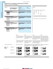
<strong>PKZ</strong>M0 motor protector trip curve<br />
The trip curve shows the tripping time of the motor protector in relation to the response current. The curve<br />
shows mean values of the tolerance ranges at an ambient temperature of 20°C, starting from cold. The tripping<br />
time of the bimetal trips at operational temperature (warm state) is reduced to approximately ¼ of the<br />
values shown. System <strong>PKZ</strong>0 motor protectors are suitable for protection of IEC type EEx - , explosion-proof<br />
motors.<br />
Specific characteristics for each individual setting range are available on request. Theses characteristics, in<br />
55 x 75 mm format, are self-adhesive and can be used as onsite documentation to verify the suitability of<br />
each motor protector for this application. The data has been independently verified by the German PTB testing<br />
agency and laboratory.<br />
Tripping time<br />
Milliseconds Seconds Minutes<br />
2h<br />
20<br />
10<br />
5<br />
40<br />
20<br />
10<br />
5<br />
2<br />
1<br />
1<br />
2<br />
200<br />
50<br />
20<br />
5<br />
2<br />
2-phase<br />
<strong>PKZ</strong>M0-...<br />
<strong>PKZ</strong>M0-.../SE00...<br />
<strong>PKZ</strong>M0-.../S00<br />
3-phase<br />
1.5 2 3 4 6 8 10 15 20 30<br />
x Rated operational current<br />
08/063<br />
1-866-595-9616<br />
1-630-595-9515 Go to: http://www.klocknermoeller.com<br />
Manual <strong>Motor</strong> <strong>Protectors</strong>,<br />
<strong>Motor</strong> Protector Combinations