Catalogue supplement XI/ON – The modular I/O ... - Moeller Electric
Catalogue supplement XI/ON – The modular I/O ... - Moeller Electric
Catalogue supplement XI/ON – The modular I/O ... - Moeller Electric

Create successful ePaper yourself
Turn your PDF publications into a flip-book with our unique Google optimized e-Paper software.
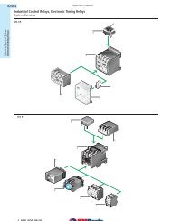
tra Combinations<br />
Bildgrösse 210 x 118,5 mm<br />
<strong>Catalogue</strong> <strong>supplement</strong><br />
<strong>XI</strong>/<strong>ON</strong> <strong>–</strong> <strong>The</strong> <strong>modular</strong> I/O System<br />
Valid from April 2002<br />
222<br />
Logo 17 x 17 mm<br />
Building Automation<br />
Industrial Automation<br />
Think future. Switch to green.<br />
Systems
<strong>XI</strong>/<strong>ON</strong> - <strong>The</strong> <strong>modular</strong> I/O system<br />
2<br />
<strong>Moeller</strong> NK2725-1042 GB
<strong>Moeller</strong> NK2725-1042 GB<br />
<strong>The</strong> <strong>XI</strong>/<strong>ON</strong> concept 4<br />
<strong>XI</strong>/<strong>ON</strong> and fieldbus protocols 8<br />
• <strong>XI</strong>/<strong>ON</strong> and PROFIBUS-DP 8<br />
• <strong>XI</strong>/<strong>ON</strong> and CANopen 10<br />
• <strong>XI</strong>/<strong>ON</strong> and DeviceNet 12<br />
<strong>XI</strong>/<strong>ON</strong> system extension and system supply 14<br />
General technical information<br />
• Formula symbols, ID colors 16<br />
• Module identification legend 17<br />
• Dimensions 18<br />
• General technical data of <strong>XI</strong>/<strong>ON</strong> modules 20<br />
Technical data 21<br />
• Gateways 21<br />
• Power distribution modules 28<br />
• Digital input modules 32<br />
• Analog input modules 40<br />
• Digital output modules 48<br />
• Analog output modules 54<br />
• Relay modules 56<br />
• Counter module 60<br />
<strong>XI</strong>/<strong>ON</strong> module guide 64<br />
XStart - industrial motor starters 66<br />
• <strong>The</strong> XStart concept 66<br />
• Technical data 68<br />
• Ordering data 69<br />
Software 70<br />
• I/Oassistant 70<br />
• DIAmon 71<br />
Accessories guide 72<br />
<strong>XI</strong>/<strong>ON</strong> and XStart product range 76<br />
Index 78<br />
Type reference list 79<br />
Contacts 86<br />
3<br />
<strong>XI</strong>/<strong>ON</strong> - <strong>The</strong> <strong>modular</strong> I/O system
<strong>The</strong> concept<br />
4<br />
<strong>The</strong> <strong>XI</strong>/<strong>ON</strong> concept<br />
<strong>The</strong> <strong>modular</strong> concept of <strong>XI</strong>/<strong>ON</strong>: gateway, block<br />
and slice design, is a combination of many<br />
benefits which, as one, represent a completely<br />
new approach to quality in the I/O field. <strong>The</strong><br />
<strong>XI</strong>/<strong>ON</strong> gateway means that I/O modules are no<br />
longer dependent on the type of fieldbus. Its<br />
function is to provide communication between<br />
the fieldbus and the I/O modules. <strong>The</strong> DIN-rail<br />
mountable base modules, available in block or<br />
slice design, represent the connection level for<br />
the field devices. <strong>The</strong> electronics modules, also<br />
available as block or slice, are pluggable, and<br />
contain the channel functions. <strong>The</strong> power<br />
distribution module (24 V DC or 120/230 V AC)<br />
supplies the interconnected I/O with the required<br />
voltage. Bus-independence, precise project<br />
planning (you only purchase the required number<br />
of channels), the high-level of compactness, the<br />
list is endless. In short: openness and flexibility<br />
are <strong>XI</strong>/<strong>ON</strong>'s strengths.<br />
Gateway<br />
• Interface between <strong>XI</strong>/<strong>ON</strong> periphery modules<br />
and the fieldbus<br />
• Supports the fieldbus protocols PROFIBUS-DP,<br />
CANopen, or INTERBUS<br />
• Coordinates the entire process data exchange<br />
• Generates diagnostic information for the<br />
higher-level controller<br />
• Fieldbus connection via direct wiring or fieldbus-specific<br />
plugs<br />
• Offers integrated interfaces for the software<br />
I/Oassistant<br />
• Enables the setting of fieldbus addresses<br />
<strong>Moeller</strong> NK2725-1042 GB<br />
Electronics module<br />
in block design<br />
Gateway<br />
Electronics module<br />
in slice design
End plate<br />
Base module<br />
in block design<br />
Base module<br />
in slice design<br />
End plate<br />
Base modules<br />
<strong>Moeller</strong> NK2725-1042 GB<br />
• Together with the integrated end bracket,<br />
it is the mechanical termination of each<br />
<strong>XI</strong>/<strong>ON</strong> station<br />
• Together with an end bracket mounted next<br />
to the gateway it guarantees the vibration<br />
resistance of the station.<br />
Electronics modules<br />
• Contain a large number of I/O functions<br />
• Communicate with the gateway via an internal<br />
module bus<br />
• Are independent of the higher-level fieldbus<br />
• Are pluggable and independent of the field<br />
wiring<br />
• Are available in slice design with 1, 2 or 4<br />
channels or in block design with 16 or 32<br />
channels<br />
• Offer type-specific color identification<br />
• Are the connection for the field wiring<br />
• Are based on terminal block technology<br />
• Are available in slice and block designs with<br />
tension clamp or screw connections<br />
• Are available in 2-/3-, and 4-wire<br />
connection technology<br />
XStart<br />
5<br />
• <strong>The</strong> <strong>XI</strong>/<strong>ON</strong> motor starters up to 4.0 kW / 400 V<br />
• DOL starters and reversing starters<br />
• Type 1 coordination to IEC/EN 60947-4-1<br />
Further information is available<br />
on pages 66 to 69<br />
<strong>The</strong> concept
<strong>The</strong> concept<br />
6<br />
<strong>XI</strong>/<strong>ON</strong> <strong>–</strong> detailed concept<br />
Openess<br />
Software I/Oassistant (optional)<br />
• Windows based<br />
• Project planning<br />
• Configuration<br />
• Parameterization<br />
• Monitoring<br />
• <strong>The</strong> gateway product palette serves the proven<br />
fieldbus systems: PROFIBUS-DP, CANopen,<br />
DeviceNet, INTERBUS<br />
• <strong>The</strong> I/O modules do not rely on a particular<br />
bus system<br />
<strong>Moeller</strong> NK2725-1042 GB<br />
Bus Refreshing<br />
module
Mechanical coding<br />
• Enables group assignment between<br />
electronics and base modules<br />
• Prevents replacement with wrong modules<br />
Bus Refreshing modules<br />
Power Feeding<br />
module<br />
• System power supply to the <strong>XI</strong>/<strong>ON</strong> modules<br />
and the gateway via the internal module bus.<br />
• Field power supply of 24 V DC to the modules<br />
• Creation of potential groups<br />
• Diagnostic functions: monitoring of the field<br />
voltage, module bus supply and module bus<br />
overload<br />
Power Feeding modules<br />
<strong>Moeller</strong> NK2725-1042 GB<br />
• Field power supply of 24 V DC or<br />
120/230 V AC to <strong>XI</strong>/<strong>ON</strong> modules<br />
• Creation of potential groups<br />
• Diagnostic function: monitoring of the<br />
field voltage<br />
Relay modules<br />
• Direct power supply when used in<br />
combination with certain base modules<br />
(e.g., XN-S4T-SBCS)<br />
• Bridging of relay roots and reduction of<br />
wiring costs with jumpers (QVR)<br />
7<br />
<strong>The</strong> concept
<strong>XI</strong>/<strong>ON</strong> and fieldbus protocols<br />
8<br />
<strong>XI</strong>/<strong>ON</strong> and PROFIBUS-DP<br />
Decentralized periphery<br />
Optimized for high speed, this PROFIBUS version<br />
is designed especially for communication<br />
between automation control systems and<br />
decentralized periphery devices. PROFIBUS-DP<br />
can be used to replace cost-intensive, parallel<br />
signal transmission from digital and analogue<br />
sensors and actuators. PROFIBUS-DP is based on<br />
DIN 19 245 Part 1 and Part 4. During the course<br />
of the European fieldbus standardization,<br />
PROFIBUS-DP has been included in the European<br />
fieldbus standard EN 50170.<br />
Maximum system extension without<br />
repeaters<br />
A PROFIBUS-DP bus line consists of at least a<br />
master and a slave. Without a repeater, a<br />
PROFIBUS-DP bus line can consist of up to 31<br />
slaves.<br />
<strong>The</strong> maximum number of 32 bus stations must<br />
not be exceeded without the use of a repeater!<br />
Maximum system extension with<br />
repeaters<br />
A maximum of 3 repeaters can be used within<br />
a PROFIBUS-DP structure. This increases the<br />
number of possible slaves to 122.<br />
<strong>The</strong> maximum number of 125 bus stations,<br />
including all slaves and repeaters, must not be<br />
exceeded!<br />
<strong>The</strong> PROFIBUS-DP addresses 000, 126 and 127<br />
are reserved and must not be used for <strong>XI</strong>/<strong>ON</strong>!<br />
Maximum bus length<br />
Baud rate<br />
(kBit/s)<br />
9.6<br />
187.5<br />
500<br />
1500<br />
3000<br />
12000<br />
max. length of a bus line<br />
without repeater (m)<br />
1200<br />
1000<br />
400<br />
200<br />
100<br />
100<br />
Topology<br />
Max. distance between two stations / cable type A<br />
(DIN 19 245 Part 3)<br />
PROFIBUS-DP communicates via a shielded<br />
twisted pair cable according to the RS 485<br />
standard. <strong>The</strong> network topology represents a<br />
linear structure with active bus termination on<br />
both ends.<br />
max. bus length<br />
with 3 repeaters (m)<br />
4800<br />
4000<br />
1600<br />
800<br />
400<br />
400<br />
<strong>Moeller</strong> NK2725-1042 GB<br />
<strong>The</strong> maximum bus length for PROFIBUS-DP<br />
depends on the transmission rate: Cable type<br />
Parameter<br />
Characteristic impedance<br />
Distributed capacitance<br />
Loop resistance<br />
Wire diameter<br />
Wire cross-section<br />
Terminating resistor<br />
Cable type A<br />
DIN 19 245 Part 3<br />
135 to 165 Ω<br />
(3 to 20 MHz)<br />
< 30 nF/km<br />
< 110 Ω/km<br />
> 0.64 mm<br />
> 0.34 mm 2<br />
220 Ω
PROFIBUS-DP system extension <strong>–</strong> <strong>XI</strong>/<strong>ON</strong> station<br />
Maximum system extension <strong>XI</strong>/<strong>ON</strong><br />
station<br />
A <strong>XI</strong>/<strong>ON</strong> station can consist of a gateway for<br />
PROFIBUS-DP and a maximum of 74 slice<br />
modules (approximately 1 m length of rail<br />
including end bracket and end plate).<br />
With the use of block modules, the maximum<br />
number of modules is correspondingly reduced<br />
(1 block module corresponds to approximately<br />
8 slice modules).<br />
Maximum station extension,<br />
process data dependent<br />
Module type<br />
Digital inputs, 4 DI<br />
Digital outputs, 4 DO<br />
Analog inputs, 2 AI-I<br />
Analog inputs, 2 AI-U<br />
Analog inputs, 2 AI-PT/Ni<br />
Analog inputs, 2 AI-THERMO<br />
Analog outputs, 2 AO-I<br />
Analog outputs, 2 AO-U<br />
Counter module, 1 CNT<br />
Channels<br />
Max. number/<br />
station<br />
288<br />
288<br />
78<br />
78<br />
46<br />
76<br />
38<br />
38<br />
7 / 7<br />
Maximum station extension,<br />
diagnostic data dependent<br />
Module type<br />
Digital inputs, 4 DI<br />
Digital outputs, 4 DO<br />
Analog inputs, 2 AI-I<br />
Analog inputs, 2 AI-U<br />
Analog inputs, 2 AI-PT/Ni<br />
Analog inputs, 2 AI-THERMO<br />
Analog outputs, 2 AO-I<br />
Analog outputs, 2 AO-U<br />
Counter module, 1 CNT<br />
Channels<br />
Max. number/<br />
station<br />
288<br />
288<br />
78<br />
78<br />
46<br />
58<br />
38<br />
38<br />
7 / 7<br />
* ... plus 2 Bus Refreshing modules<br />
**...plus 1 Bus Refreshing module<br />
1) ... Standard GSD file; not compressed module description<br />
2) ... Extended GSD file; not compressed module description<br />
Modules<br />
Max. number/<br />
station<br />
72 * 1)<br />
72 * 1)<br />
39 * 1)<br />
39 * 1)<br />
23 ** 1)<br />
38 * 1)<br />
19 ** 2)<br />
19 ** 2)<br />
7 ** 1)<br />
Modules<br />
Max. number/<br />
station<br />
72 * 1)<br />
72 * 1)<br />
39 * 1)<br />
39 * 1)<br />
23 ** 1)<br />
29 * 1)<br />
19 ** 2)<br />
19 ** 2)<br />
7 ** 1)<br />
<strong>Moeller</strong> NK2725-1042 GB<br />
Ensure that a sufficient number of Power<br />
Feeding or Bus Refreshing modules are used<br />
if the system is extended to its maximum.<br />
If the system limits are exceeded, the<br />
software I/Oassistant generates an error<br />
message when the user activates the<br />
command .<br />
9<br />
<strong>XI</strong>/<strong>ON</strong> and fieldbus protocols
<strong>XI</strong>/<strong>ON</strong> and fieldbus protocols<br />
10<br />
<strong>XI</strong>/<strong>ON</strong> and CANopen<br />
Bus system CANopen<br />
CANopen is a network that is based on the<br />
serial, two-wire transfer of Controller Area<br />
Networks (CAN).<br />
CANopen uses the international CAN standard<br />
ISO 11 898 as the basis for communications with<br />
an open network. This standard covers layers<br />
1 and 2 (physical and data link layer) of the<br />
ISO/OSI communication model.<br />
Building on this, the CANopen family of profiles<br />
were developed by the international user and<br />
manufacture organization CiA (CAN in<br />
Automation).<br />
This family of profiles comprises, on the one<br />
hand, the communication profile CiA DS 301,<br />
which represents ISO/OSI layer 7 (Application<br />
Layer) and which specifies the communication<br />
mechanisms. And on the other hand, a number<br />
of device (CiA DS 40x) profiles which specify the<br />
device functionality.<br />
Maximum bus length<br />
<strong>The</strong> maximum bus length for CANopen is<br />
dependent on the rate of transmission:<br />
Baud rate (kBit/s)<br />
10<br />
20<br />
50<br />
100<br />
125<br />
250<br />
500<br />
800<br />
1 000<br />
Max.<br />
wire length (m)<br />
1 000<br />
1 000<br />
1 000<br />
650<br />
500<br />
250<br />
100<br />
50<br />
25<br />
Maximum system extension<br />
A CANopen bus line consists of at least two<br />
stations. <strong>The</strong>se could be a PC or PLC, and a<br />
<strong>XI</strong>/<strong>ON</strong> gateway, for example.<br />
A bus line can consist of a maximum of 110<br />
stations (for example, <strong>XI</strong>/<strong>ON</strong> gateways).<br />
<strong>The</strong> use of repeaters can become necessary with<br />
bus lengths of more than 1 000 m.<br />
<strong>The</strong> CANopen Address 000 is reserved for<br />
telegrams to all stations and must not be used<br />
as a station address!<br />
Topology<br />
CANopen is based on a linear topology utilizing<br />
shielded, twisted-pair cabling with bus terminators<br />
at both ends of the bus line in accordance<br />
with ISO-DIS 11 898.<br />
Parameters<br />
Impedance<br />
Resistivety<br />
Conduction delay<br />
Terminating resistance<br />
ISO-DIS 11 898<br />
108 to 132 Ω<br />
70 mΩ/m<br />
5 ns/m<br />
120 Ω<br />
<strong>Moeller</strong> NK2725-1042 GB<br />
Mixed operation with other devices<br />
Within a CANopen structure, <strong>XI</strong>/<strong>ON</strong> can be used<br />
in conjunction with CANopen conform field bus<br />
devices from various manufacturers.
CANopen system extension <strong>–</strong> <strong>XI</strong>/<strong>ON</strong> station<br />
Maximum system extension <strong>XI</strong>/<strong>ON</strong><br />
station<br />
A <strong>XI</strong>/<strong>ON</strong> station can consist of a gateway for<br />
CANopen and a maximum of 74 slice<br />
modules (approximately 1 m length of rail<br />
including end bracket and end plate).<br />
With the use of block modules, the maximum<br />
number of modules is correspondingly reduced<br />
(1 block module corresponds to approximately 8<br />
slice modules).<br />
Module type<br />
Digital inputs, 4 DI<br />
Digital outputs, 4 DO<br />
Analog inputs, 2 AI-I<br />
Analog inputs, 2 AI-U<br />
Analog inputs, 2 AI-PT/Ni<br />
or 2 AI-THERMO<br />
Analog outputs, 2 AO-I<br />
Analog outputs, 2 AO-U<br />
Counter module, 1 CNT<br />
Ensure that a sufficient number of Power<br />
Feeding or Bus Refreshing modules are used<br />
if the system is extended to its maximum.<br />
If the system limits are exceeded, the<br />
software I/Oassistant generates an error<br />
message when the user activates the<br />
command .<br />
* ... plus 2 Bus Refreshing modules<br />
**... plus 3 Bus Refreshing modules<br />
Channels<br />
Max. number/<br />
station<br />
288<br />
288<br />
142<br />
142<br />
142<br />
142<br />
142<br />
71 / 71<br />
Modules<br />
Max. number/<br />
station<br />
72 *<br />
72 *<br />
71 **<br />
71 **<br />
71 **<br />
71 **<br />
71 **<br />
71 **<br />
<strong>Moeller</strong> NK2725-1042 GB<br />
11<br />
<strong>XI</strong>/<strong>ON</strong> and fieldbus protocols
<strong>XI</strong>/<strong>ON</strong> and fieldbus protocols<br />
12<br />
<strong>XI</strong>/<strong>ON</strong> and DeviceNet<br />
Bus system DeviceNet<br />
<strong>The</strong> open, low-end network, DeviceNet, is based<br />
on CAN technology.<br />
<strong>The</strong> communication profile used by <strong>XI</strong>/<strong>ON</strong><br />
contains:<br />
• UCMM<br />
• Offline Connection Set<br />
• Polled I/O<br />
• COS/Cyclic<br />
• Bitstrobe<br />
• Device Heartbeat Message<br />
• Device Shut Sown Message<br />
<strong>The</strong> user can select a master/slave, multi master<br />
or a combined configuration, depending on<br />
application requirements.<br />
Maximum bus length<br />
<strong>The</strong> DeviceNet specifications permit the use of<br />
two types of cable: thick and thin.<br />
Depending on the type of cable used, the<br />
following maximum bus lengths for the three<br />
possible transfer rates are possible:<br />
Baud rate<br />
(kBit/s)<br />
125<br />
250<br />
500<br />
Maximum system extension<br />
Max. distance between 2 stations<br />
100 % thick Cable<br />
500 m (1640 ft)<br />
250 m (820 ft)<br />
100 m (328 ft)<br />
<strong>The</strong> branches can be up to 6 m (20 ft) long, but<br />
the total extent of all branches depends on the<br />
baud rate.<br />
A DeviceNet bus line consists of a scanner and<br />
at least another bus station.<br />
<strong>The</strong> maximum number of 64 bus stations<br />
(including the scanner) must not be exceeded.<br />
Mixed operation with other devices<br />
Within a DeviceNet structure, <strong>XI</strong>/<strong>ON</strong> can be<br />
used in conjunction with standardized DeviceNet<br />
fieldbus devices from various manufacturers.<br />
Topology<br />
DeviceNet uses a full trunk / branch line<br />
topology with up to 64 nodes.<br />
100 % thin Cable<br />
100 m (328 ft)<br />
<strong>Moeller</strong> NK2725-1042 GB
DeviceNet system extension - <strong>XI</strong>/<strong>ON</strong> station<br />
Maximum system extension <strong>XI</strong>/<strong>ON</strong><br />
station<br />
A <strong>XI</strong>/<strong>ON</strong> station can consist of a gateway for<br />
DeviceNet and a maximum of 74 slice<br />
modules (approximately 1 m length of rail<br />
including end bracket and end plate).<br />
With the use of block modules, the maximum<br />
number of modules is correspondingly reduced<br />
(1 block module corresponds to approximately<br />
8 slice modules).<br />
Module type<br />
Digital inputs, 4 DI<br />
Digital outputs, 4 DO<br />
Analog inputs, 2 AI-I<br />
Analog inputs, 2 AI-U<br />
Analog inputs, 2 AI-PT/Ni<br />
or 2 AI-THERMO<br />
Analog outputs, 2 AO-I<br />
Analog outputs, 2 AO-U<br />
Counter module, 1 CNT<br />
Ensure that a sufficient number of Power<br />
Feeding or Bus Refreshing modules are used<br />
if the system is extended to its maximum.<br />
If the system limits are exceeded, the<br />
software I/Oassistant generates an error<br />
message when the user activates the<br />
command .<br />
* ... plus 2 Bus Refreshing modules<br />
** ...plus 3 Bus Refreshing module<br />
Channels<br />
Max. number/<br />
station<br />
288<br />
288<br />
142<br />
142<br />
126<br />
126<br />
126<br />
31/31<br />
Modules<br />
Max. number/<br />
station<br />
72 *<br />
72 *<br />
71 **<br />
71 **<br />
63 **<br />
63 **<br />
63 **<br />
31*<br />
<strong>Moeller</strong> NK2725-1042 GB<br />
13<br />
<strong>XI</strong>/<strong>ON</strong> and fieldbus protocols
System extension and system supply<br />
14<br />
<strong>XI</strong>/<strong>ON</strong> system extension<br />
General system supply<br />
<strong>The</strong> power supply to a <strong>XI</strong>/<strong>ON</strong> station is fed<br />
via Power Feeding or Bus Refreshing modules,<br />
the latter also being responsible for the power<br />
supply to the internal module bus.<br />
Bus Refreshing modules are used within a <strong>XI</strong>/<strong>ON</strong><br />
station (without gateway supply) if the system<br />
supply to the <strong>XI</strong>/<strong>ON</strong> modules (nominal current<br />
IMB ≥ 1.5 A) is no longer sufficiently guaranteed.<br />
<strong>The</strong>se Bus Refreshing modules are to be<br />
combined with the base modules XN-P3T-SBB-B<br />
or XN-P4T-SBBC-B (tension clamp connections)<br />
or with the base modules XN-P3S-SBB-B or<br />
XN-P4S-SBBC-B (screw connections).<br />
Power Feeding modules are used if the system<br />
supply to the <strong>XI</strong>/<strong>ON</strong> modules (nominal current<br />
IEL ≥ 10 A) is no longer sufficiently guaranteed.<br />
Nominal current consumption<br />
<strong>The</strong> following table offers an overview of the<br />
nominal current consumption of the different<br />
<strong>XI</strong>/<strong>ON</strong> modules on the module bus:<br />
Module<br />
Gateway PROFIBUS-DP<br />
Gateway CANopen<br />
Gateway DeviceNet<br />
XN-BR-24VDC-D<br />
XN-PF-24VDC-D<br />
XN-PF-120/230VAC-D<br />
XN-2DI-24VDC-P<br />
XN-2DI-24VDC-N<br />
XN-2DI-120/230VAC-P<br />
XN-4DI-24VDC-P<br />
XN-4DI-24VDC-N<br />
XN-16DI-24VDC-P<br />
XN-32DI-24VDC-P<br />
XN-1AI-I(0/4..20MA)<br />
XN-2AI-I(0/4...20MA)<br />
XN-1AI-U(-10/0..+10VDC)<br />
XN-2AI-U(-10/0...+10VDC)<br />
XN-2DO-24VDC-0.5A-P<br />
XN-2DO-24VDC-0.5A-N<br />
XN-2DO-24VDC-2A-P<br />
XN-4DO-24VDC-0.5A-P<br />
XN-16DO-24VDC-0.5A-P<br />
XN-1AO-I(0/4..20MA)<br />
XN-2AO-I(0/4...20MA)<br />
XN-2A0-U(-10/0..+10VDC)<br />
XN-2DO-R-NC<br />
XN-2DO-R-NO<br />
XN-2DO-R-CO<br />
XN-1CNT<br />
Power<br />
supply IMB<br />
1500 mA<br />
System supply <strong>XI</strong>/<strong>ON</strong> gateway<br />
<strong>The</strong> first module on a <strong>XI</strong>/<strong>ON</strong> station after the<br />
<strong>XI</strong>/<strong>ON</strong> gateway must always be a Bus Refreshing<br />
module as well as the corresponding base<br />
module XN-P3x-SBB or XN-P4x-SBBC with<br />
tension clamp or screw connection to supply<br />
the gateway.<br />
Nominal<br />
current IMB<br />
≤ 430 mA<br />
≤ 350 mA<br />
≤ 250 mA<br />
≤ 28 mA<br />
≤ 25 mA<br />
≤ 28 mA<br />
≤ 28 mA<br />
≤ 28 mA<br />
≤ 29 mA<br />
≤ 28 mA<br />
≤ 45 mA<br />
≤ 30 mA<br />
≤ 41 mA<br />
≤ 35 mA<br />
≤ 41 mA<br />
≤ 35 mA<br />
≤ 32 mA<br />
≤ 32 mA<br />
≤ 33 mA<br />
≤ 30 mA<br />
≤ 45 mA<br />
≤ 39 mA<br />
≤ 43 mA<br />
≤ 43 mA<br />
≤ 28 mA<br />
≤ 28 mA<br />
≤ 28 mA<br />
< 40 mA<br />
<strong>Moeller</strong> NK2725-1042 GB<br />
System supply via module bus<br />
<strong>The</strong> number of <strong>XI</strong>/<strong>ON</strong> modules that can be<br />
supplied by a Bus Refreshing module via the<br />
internal module bus depends on the respective<br />
nominal current IMB of the individual modules on<br />
the module bus.<br />
<strong>The</strong> sum total of the nominal current inputs of<br />
the connected <strong>XI</strong>/<strong>ON</strong> modules must not exceed<br />
1.5 A.<br />
<strong>The</strong> power requirements of the <strong>XI</strong>/<strong>ON</strong> gateway<br />
supplied via the first Bus Refreshing module<br />
in the station is to be is to be taken into<br />
consideration when calculating the required<br />
number of Bus Refreshing modules.<br />
If the software I/Oassistant is used, an error<br />
message is generated automatically via the<br />
as soon as the system supply<br />
via the module bus in no longer sufficiently<br />
guaranteed.<br />
All Bus Refreshing modules used in a <strong>XI</strong>/<strong>ON</strong><br />
station are to be connected via the same frame<br />
potential.<br />
<strong>The</strong> power supply to the module bus is fed via<br />
the connections 11 (plus) and 21 (ground) of the<br />
respective base module for the Bus Refreshing<br />
module.<br />
Creating potential groups<br />
Both Bus Refreshing modules as well as Power<br />
Feeding modules can be used to create a<br />
potential group.<br />
<strong>The</strong> potential isolation of the potential group<br />
on the left-hand side of the respective power<br />
distribution module is created by the base<br />
module.<br />
It is not permitted for modules with 24 V DC and<br />
with 120/230 V AC field supply to be used in a<br />
joint potential group.<br />
<strong>The</strong>refore, it must be observed that when using<br />
digital input modules for 120/230 V AC the<br />
Power Feeding module XN-PF-120/230VAC-D is<br />
to be used to create a special potential group.
<strong>XI</strong>/<strong>ON</strong> system supply<br />
C-rail (cross connection)<br />
<strong>The</strong> C-rails run through all I/O base modules.<br />
<strong>The</strong> C-rail of the base modules for power<br />
distribution modules is mechanically separated;<br />
thus potentially isolating the adjoining supply<br />
groups.<br />
Using the C-rail as a protective earth<br />
<strong>The</strong> C-rail can be used as required in the<br />
application, for example, as a protective earth<br />
(PE). In this case, the PE connection of each<br />
power distribution module must be connected<br />
to the mounting rail via an additional PE<br />
terminal, which is available as an accessory.<br />
PE<br />
terminal<br />
Gateway<br />
SHLD<br />
DGND<br />
VP<br />
A<br />
B<br />
SHLD<br />
DGND<br />
VP<br />
A<br />
B<br />
<strong>XI</strong>/<strong>ON</strong><br />
BR<br />
11 21 11 21 11 21 11 21 11 21 11 21 11<br />
12 22 12 22 12 22 12 22 12 22 12 22 12<br />
13 23 13 23 13 23 13 23 13 23 13 23 13<br />
Acces to the C-rail<br />
Access to the C-rail is be made via base modules<br />
with a C in their designation (for example,<br />
XN-S4T-SBCS). <strong>The</strong> corresponding connection<br />
level is indicated on these modules by a thick<br />
black line, which is continuous on all base<br />
modules for <strong>XI</strong>/<strong>ON</strong> I/O modules. With base<br />
modules for power distribution modules, the<br />
black line is above the connection 24 only. This<br />
makes clear that the C-rail is separated from the<br />
adjoining potential group to its left.<br />
It is permitted to load the C-rail with a maximum<br />
of 24 V! Never with 120/230 V AC.<br />
<strong>The</strong> C-rail can be used as required in the<br />
application, for example, as a protective earth<br />
(PE). In this case, the PE connection of each<br />
power distribution module must be connected to<br />
the mounting rail via an additional PE terminal,<br />
which is available as an accessory.<br />
21 11<br />
22 12<br />
23 13<br />
21 11 21 11 21<br />
22 12 22 12 22<br />
23 13 23 13 23<br />
C-rail (PE) C-rail (PE)<br />
14 24 14 24<br />
14 24<br />
14 24<br />
SBBC<br />
2 DO 2 DI 2 DO 2 DI<br />
SBC<br />
SBBC<br />
SBC<br />
SBB<br />
PF<br />
SBBC<br />
2 DO 2 DI 2 DO 2 DI<br />
SBC<br />
SBBC<br />
SBC<br />
SBB<br />
TS<br />
<strong>Moeller</strong> NK2725-1042 GB<br />
Using the C-rail with relay modules<br />
15<br />
<strong>The</strong> C-rail can be used to supply a common<br />
voltage when relay modules are to be used.<br />
To accomplish this, the load voltage (24 V DC) is<br />
connected to a power distribution module with<br />
the base module XN-P4x-SBBC with either<br />
tension clamp or screw connection. All the<br />
following relay modules are supplied with<br />
24 V DC via the C-rail a.<br />
<strong>The</strong> cross-connection of the individual relay<br />
modules is achieved using the cross-connector<br />
QVR b.<br />
If the C-rail is to be used for the joint supply of<br />
voltage to relay modules, then there must<br />
subsequently be a further power distribution<br />
module used for the potential isolation of the<br />
following <strong>XI</strong>/<strong>ON</strong> modules.<br />
<strong>The</strong> C-rail can again be put on other uses<br />
(for example, as a PE) once the potential<br />
isolation has been made.<br />
System extension and system supply
General technical information<br />
16<br />
Formula symbols / ID colors for <strong>XI</strong>/<strong>ON</strong> electronics modules<br />
Abbreviation<br />
GND<br />
IA<br />
IEl<br />
IH<br />
II<br />
IL<br />
IMB<br />
L-<br />
L+<br />
PE<br />
RLI<br />
RLK<br />
RLL<br />
RLO<br />
S<br />
Sh<br />
UA<br />
UH<br />
UI<br />
Uh<br />
UL<br />
UL<br />
UPF<br />
Usys<br />
Electronics module<br />
Gateway<br />
Bus Refreshing modules 24 V DC<br />
Power Feeding modules 24 V DC<br />
Designation<br />
Power Feeding modules 120/230 V AC<br />
Digital input modules<br />
Analog input modules<br />
Digital output modules<br />
Analog output modules<br />
Relay modules<br />
Technology modules (counter module)<br />
Ground<br />
Active level current (with negative switching electronics modules)<br />
<strong>Electric</strong>al operating supply (field voltage)<br />
High-level current<br />
Inactive level current (with negative switching electronics modules)<br />
Low-level current<br />
Current via the module bus<br />
Neutral conductor<br />
Positive conductor<br />
Protective earth conductor<br />
Load impedance, inductive<br />
Load impedance, capacitive<br />
Lamp load<br />
Resistive load<br />
Signal cable<br />
Shielding<br />
Active level voltage (with negative switching electronics modules)<br />
High-level voltage<br />
Inactive level voltage (with negative switching electronics modules)<br />
Auxiliary voltage for analog valuator sensor<br />
Field supply with LEDs<br />
Low-level voltage<br />
Voltage that is presently being supplied via the power distribution module<br />
System supply<br />
ID color<br />
dusty grey<br />
dusty grey<br />
dusty grey<br />
orange brown<br />
light grey<br />
pigeon blue<br />
strawberry red<br />
pale green<br />
pastel orange<br />
zinc yellow<br />
<strong>Moeller</strong> NK2725-1042 GB
Module identification legend<br />
ID<br />
ABPL<br />
AI<br />
AO<br />
B<br />
B<br />
B<br />
BR<br />
C<br />
CJ<br />
CNT<br />
CO<br />
D<br />
DI<br />
DO<br />
GW<br />
KLBU<br />
KO<br />
MB<br />
N<br />
NC<br />
NI<br />
NO<br />
P<br />
P<br />
PBDP<br />
PF<br />
PI<br />
PT<br />
QV<br />
R<br />
S<br />
S<br />
S<br />
S<br />
T<br />
x<br />
Designation<br />
End plate for right-sided termination of a <strong>XI</strong>/<strong>ON</strong> station<br />
Analog input module<br />
Analog output module<br />
Designation for base module in block design<br />
Bridge connector: bridged connections on the same<br />
connection level in a base module, for applying potentials<br />
Added to designation of base modules for those Bus Refreshing<br />
modules used within a <strong>XI</strong>/<strong>ON</strong> station but do not supply the<br />
gateway with power.<br />
Bus Refreshing module<br />
Designation of a connection level with cross-connection to a C-rail<br />
and can, among other things, be used as a PE (only possible with<br />
certain base modules).<br />
Base module for XN-2AI-THERMO-PI with integrated PT100 for<br />
cold junction compensation<br />
Counter<br />
Changeover<br />
Diagnostics<br />
Digital input module<br />
Digital output module<br />
Gateway<br />
Terminal clip, shield connection for analog input modules<br />
Coding element for coding electronics and base modules<br />
MBaud (MBit/s); transmission rate for data transfer<br />
Negative switching<br />
Normally closed<br />
for connecting resistance thermometers<br />
with sensors Ni100 and Ni1000 in 2- or 3-wire<br />
measurement type<br />
Normally open<br />
Positive switching<br />
Designation of the base module for Power Feeding and Bus Refreshing<br />
modules<br />
<strong>XI</strong>/<strong>ON</strong>-Gateway for PROFIBUS-DP<br />
Power Feeding modules<br />
Analog input module for connecting thermoelements with<br />
cold junction compensation<br />
Analog input module for connecting resistance thermometers<br />
with sensors PT100, PT500 and PT1000 in 2- or 3-wire<br />
measurement type<br />
Jumper for relay modules<br />
Relay module<br />
Designation for base module in slice design<br />
Designation for base modules with screw connection<br />
Designation for gateway with screw connection<br />
Single connector: non-bridged connections on the same<br />
connection level in a base module, used for connecting the signal<br />
Designation for base modules with tension<br />
clamp connection<br />
Partly for “S” or “T” in the designations of base modules with<br />
screw or tension clamp connections<br />
<strong>Moeller</strong> NK2725-1042 GB<br />
Examples<br />
XN-ABPL<br />
XN-1AI-U(-10/0...+10VDC)<br />
XN-1AO-I(0/4...20MA)<br />
XN-B3S-SBB<br />
XN-S3T-SBB<br />
XN-P4T-SBBC-B<br />
XN-BR-24VDC-D<br />
XN-S4T-SBBC<br />
XN-S4T-SBBS-CJ<br />
XN-1CNT-24VDC<br />
XN-2DO-R-CO<br />
XN-BR-24VDC-D<br />
XN-2DI-24VDC-P<br />
XN-2DO-24VDC-2A-P<br />
XN-GW-PBDP-1.5MB<br />
XN-KLBU/T<br />
XN-KO/2<br />
XN-GW-PBDP-1.5MB<br />
XN-2DI-24VDC-N<br />
XN-2DO-R-NC<br />
XN-2AI-PT/NI-2/3<br />
XN-2DO-R-NO<br />
XN-2DI-24VDC-P<br />
XN-P3T-SBB<br />
XN-GW-PBDP-1.5MB<br />
XN-PF-24VDC-D<br />
XN-2AI-THERMO-PI<br />
XN-2AI-PT/NI-2/3<br />
XN-QV/1<br />
XN-2DO-R-NC<br />
XN-S3T-SBB<br />
XN-S3S-SBB<br />
XN-GW-PBDP-1.5MB-S<br />
XN-S3T-SBB<br />
XN-S3T-SBB<br />
XN-S3x-SBB<br />
17
General technical information<br />
18<br />
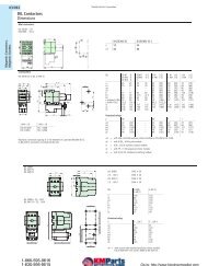
Dimensions<br />
Electronics modules<br />
in slice design<br />
in block design<br />
Base modules<br />
in slice design<br />
2-/3-wire connection technology<br />
4-wire connection technology<br />
4 x 2-/3-wire connection technology<br />
in block design<br />
2-/3-wire connection technology<br />
4-wire connection technology<br />
32 x 2-/3-wire connection technology<br />
Dimensions in mm (W x L x H)<br />
12.6 x 74.1 x 55.4<br />
100.8 x 74.1 x 55.4<br />
12.6 x 117.6 x 49.9<br />
12.6 x 128.9 x 49.9<br />
12.6 x 154.5 x 49.9<br />
100.8 x 117.6 x 49.9<br />
100.8 x 128.9 x 49.9<br />
100.8 x 154.5 x 49.9<br />
Complete <strong>XI</strong>/<strong>ON</strong> module (slice design; base module with tension clamp connection<br />
Electronics module in slice design<br />
Electronics module in block design<br />
<strong>Moeller</strong> NK2725-1042 GB
Base module with tension clamp connection (side view)<br />
Base module with screw connection (side view)<br />
Base module in slice design (top view)<br />
Base module in block design (top view)<br />
<strong>Moeller</strong> NK2725-1042 GB<br />
19<br />
General technical information
General technical information<br />
20<br />
General technical data <strong>XI</strong>/<strong>ON</strong><br />
General technical data<br />
<strong>XI</strong>/<strong>ON</strong> allgemein<br />
Potential isolation<br />
Ambient temperature<br />
Operating temperature<br />
Storage temperature<br />
Relative humidity<br />
Noxious gas<br />
SO2<br />
H2S<br />
Resistant to vibration<br />
Operating conditions<br />
Resistant to shock<br />
Resistant to repetitive shock<br />
Topple and fall<br />
Protection class<br />
Electromagnetic compatibility (EMC)<br />
Tests<br />
Base modules<br />
Measurement data<br />
Connection technology in TOP construction<br />
Insulation stripping length<br />
Crimpable wire<br />
Nominal diameter<br />
"e" solid core H 07V-U<br />
"f" flexible core H 07V-K<br />
"f" with ferrules according to DIN 46 228/1<br />
(ferrules crimped gas-tight)<br />
Plug gauge according to IEC 947-1/1988<br />
Protection class<br />
Approvals<br />
via optocoupler<br />
<strong>Moeller</strong> NK2725-1042 GB<br />
32 °F to +131 °F (0 to +55 °C)<br />
-13 °F to +185 °F (-25 to +85 °C)<br />
5 to 95 % (indoor), Level RH-2, without condensation (storage at 45 °C)<br />
10 ppm (rel. humidity < 75 %, without condensation)<br />
1.0 ppm (rel. humidity < 75 %, without condensation)<br />
according to EN 61 131<br />
according to EN 61 131<br />
according to IEC 68-2-27<br />
according to IEC 68-2-29<br />
according to IEC 68-2-31 and free fall according to IEC 68-2-32<br />
IP 20<br />
according to EN 50 082-2 (Industry)<br />
according to EN 61 131-2<br />
according to VDE 0611 Teil 1/8.92 / IEC 947-7-1/1989<br />
tension clamp or screw connection<br />
8 mm<br />
1.5 mm 2<br />
0.5 to 2.5 mm 2<br />
0.5 to 1.5 mm 2<br />
0.5 to 1.5 mm 2<br />
A1<br />
IP 20<br />
CE<br />
UL<br />
CSA
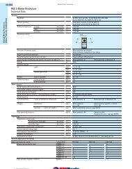
Technical data <strong>–</strong> Gateways<br />
Gateway PROFIBUS DP<br />
Gateway overview:<br />
• <strong>The</strong> gateway is the interface between the <strong>XI</strong>/<strong>ON</strong><br />
periphery modules and PROFIBUS-DP<br />
• It is responsible for the data exchange between the<br />
<strong>XI</strong>/<strong>ON</strong> station and the PROFIBUS-DP master<br />
• <strong>The</strong> connection to the PROFIBUS-DP is made via<br />
9-pole SUB-D socket or by direct wiring<br />
• Hexadecimal rotary switches for setting the<br />
PROFIBUS-DP station address (001 - 125)<br />
• LEDs for indicating supply voltage, group or bus<br />
errors<br />
<strong>XI</strong>/<strong>ON</strong> Gateway PROFIBUS<br />
Supply voltage<br />
Permissible range<br />
Residual ripple<br />
Nominal current consumption from module bus IMB<br />
Service interface<br />
Connection technology fieldbus<br />
Connection technology for direct wiring<br />
Transmission speed<br />
Fieldbus addressing<br />
Fieldbus termination<br />
Passive LWL adapters can be connected<br />
Number of parameter bytes<br />
Number of diagnostic bytes<br />
Address range for PROFIBUS-DP<br />
Width/length/height<br />
Included in range of supply<br />
Ordering information<br />
Type<br />
XN-GW-PBDP-1.5MB<br />
Catalog number<br />
225162<br />
XN-GW-PBDP-1.5MB (tension clamp)<br />
5 V DC (from Bus Refreshing module)<br />
4.7 to 5.3 V DC<br />
according to EN 61 131-2<br />
≤ 430 mA<br />
PS/2 socket<br />
2x SUB-D sockets, 9-pole<br />
2x direct wiring, 5-pole<br />
Tension clamp<br />
9.6 kBit/s to 1.5 MBit/s<br />
2 hexadecimal rotary switches<br />
via SUB-D connector<br />
Current consumption max. 100 mA<br />
5 Bytes<br />
3 Bytes<br />
001 to 125 dec.<br />
50.6 x 114.8 x 74.4 mm<br />
2x end bracket XN-WEW-35/2-SW<br />
1x end plate XN-ABPL5<br />
<strong>Moeller</strong> NK2725-1042 GB<br />
21<br />
Technical data
22<br />
Technical data <strong>–</strong> Gateways<br />
Gateway PROFIBUS DP<br />
Gateway overview:<br />
• <strong>The</strong> gateway is the interface between the <strong>XI</strong>/<strong>ON</strong><br />
periphery modules and PROFIBUS-DP<br />
• It is responsible for the data exchange between the<br />
<strong>XI</strong>/<strong>ON</strong> station and the PROFIBUS-DP master<br />
• <strong>The</strong> connection to the PROFIBUS-DP is made via<br />
9-pole SUB-D socket or by direct wiring<br />
• Hexadecimal rotary switches for setting the<br />
PROFIBUS-DP station address (001 - 125)<br />
• LEDs for indicating supply voltage, group or bus<br />
errors<br />
<strong>XI</strong>/<strong>ON</strong> Gateway PROFIBUS<br />
Supply voltage<br />
Permissible range<br />
Residual ripple<br />
Nominal current consumption from module bus IMB<br />
Service interface<br />
Connection technology fieldbus<br />
Connection technology for direct wiring<br />
Transmission speed<br />
Fieldbus addressing<br />
Fieldbus termination<br />
Passive LWL adapters can be connected<br />
Number of parameter bytes<br />
Number of diagnostic bytes<br />
Address range for PROFIBUS-DP<br />
Width/length/height<br />
Included in range of supply<br />
Ordering information<br />
Type<br />
XN-GW-PBDP-1.5MB-S<br />
Catalog number<br />
227852<br />
XN-GW-PBDP-1.5MB-S (Screw connection)<br />
5 V DC (from Bus Refreshing module)<br />
4.7 to 5.3 V DC<br />
according to EN 61 131-2<br />
≤ 430 mA<br />
PS/2 socket<br />
2x SUB-D sockets, 9-pole<br />
2x direct wiring, 5-pole<br />
Screw connection<br />
9.6 kBit/s to 1.5 MBit/s<br />
2 hexadecimal rotary switches<br />
via SUB-D connector<br />
Current consumption max. 100 mA<br />
5 Bytes<br />
3 Bytes<br />
001 to 125 dec.<br />
50.6 x 114.8 x 74.4 mm<br />
2x end bracket XN-WEW-35/2-SW<br />
1x end plate XN-ABPL5<br />
<strong>Moeller</strong> NK2725-1042 GB
Technical data <strong>–</strong> Gateways<br />
Gateway PROFIBUS DP<br />
Gateway overview:<br />
• <strong>The</strong> gateway is the interface between the <strong>XI</strong>/<strong>ON</strong><br />
periphery modules and PROFIBUS-DP<br />
• It is responsible for the data exchange between the<br />
<strong>XI</strong>/<strong>ON</strong> station and the PROFIBUS-DP master<br />
• <strong>The</strong> connection to the PROFIBUS-DP is made via<br />
9-pole SUB-D socket<br />
• Hexadecimal rotary switches for setting the<br />
PROFIBUS-DP station address (001 - 125)<br />
• LEDs for indicating supply voltage, group or bus<br />
errors<br />
<strong>XI</strong>/<strong>ON</strong> Gateway PROFIBUS<br />
Supply voltage<br />
Permissible range<br />
Residual ripple<br />
Nominal current consumption from module bus IMB<br />
Service interface<br />
Connection technology fieldbus<br />
Transmission speed<br />
Fieldbus addressing<br />
Fieldbus termination<br />
Passive LWL adapters can be connected<br />
Number of parameter bytes<br />
Number of diagnostic bytes<br />
Address range for PROFIBUS-DP<br />
Width/length/height<br />
Included in range of supply<br />
Ordering information<br />
Type<br />
XN-GW-PBDP-12MB<br />
Catalog number<br />
225161<br />
XN-GW-PBDP-12MB<br />
5 V DC (from Bus Refreshing module)<br />
4.7 to 5.3 V DC<br />
according to EN 61 131-2<br />
≤ 430 mA<br />
PS/2 socket<br />
1 SUB-D socket, 9-pole<br />
9.6 kBit/s to 12 MBit/s<br />
2 hexadecimal rotary switches<br />
via SUB-D connector<br />
Current consumption max. 100 mA<br />
5 Bytes<br />
3 Bytes<br />
001 to 125 dec.<br />
50.6 x 114.8 x 74.4 mm<br />
2x end bracket XN-WEW-35/2-SW<br />
1x end plate XN-ABPL<br />
<strong>Moeller</strong> NK2725-1042 GB<br />
23
24<br />
Technical data <strong>–</strong> Gateways<br />
Gateway PROFIBUS DP<br />
Gateway overview:<br />
This gateway contains the same features as the<br />
gateway XN-GW-PBDP-12MB with the following restrictions:<br />
• Max. 15 <strong>XI</strong>/<strong>ON</strong> I/O modules are connectable,<br />
• including max. 4 block modules.<br />
• <strong>The</strong> software I/Oassistant can only be used online<br />
for firmware download.<br />
• <strong>The</strong> packing of modules process data is not<br />
supported.<br />
<strong>XI</strong>/<strong>ON</strong> Gateway PROFIBUS<br />
Supply voltage<br />
Permissible range<br />
Residual ripple<br />
Nominal current consumption from module bus IMB<br />
Service interface<br />
Connection technology fieldbus<br />
Transmission speed<br />
Fieldbus addressing<br />
Fieldbus termination<br />
Passive LWL adapters can be connected<br />
Number of parameter bytes<br />
Number of diagnostic bytes<br />
Address range for PROFIBUS-DP<br />
Width/length/height<br />
Included in range of supply<br />
Ordering information<br />
Type<br />
XN-GW-PBDP-12MB-STD<br />
Catalog number<br />
229499<br />
XN-GW-PBDP-12MB-STD<br />
5 V DC (from Bus Refreshing module)<br />
4.7 to 5.3 V DC<br />
according to EN 61 131-2<br />
≤ 410 mA<br />
only for firmware download<br />
1 SUB-D socket, 9-pole<br />
9.6 kBit/s to 12 MBit/s<br />
2 hexadecimal rotary switches<br />
via SUB-D connector<br />
Current consumption max. 100 mA<br />
5 Bytes<br />
3 Bytes<br />
001 to 125 dec.<br />
50.6 x 114.8 x 74.4 mm<br />
2x end bracket XN-WEW-35/2-SW<br />
1x end plate XN-ABPL<br />
<strong>Moeller</strong> NK2725-1042 GB
Technical data <strong>–</strong> Gateways<br />
Gateway DeviceNet<br />
Gateway overview<br />
• <strong>The</strong> gateway is the interface between the <strong>XI</strong>/<strong>ON</strong><br />
periphery modules and the DeviceNet<br />
• It is responsible for the data exchange between the<br />
<strong>XI</strong>/<strong>ON</strong> station and further DeviceNet stations<br />
• <strong>The</strong> connection to the DeviceNet is made via Open<br />
Style Connector<br />
• LEDs for indicating supply voltage, group diagnostics<br />
and bus errors<br />
<strong>XI</strong>/<strong>ON</strong> Gateway DeviceNet<br />
Supply voltage<br />
Permissible range<br />
Residual ripple<br />
Nominal current from module bus IMB<br />
Service interface<br />
Connection technology fieldbus<br />
Transmission speed<br />
Fieldbus addressing<br />
Fieldbus termination<br />
Address range<br />
Width/length/height<br />
Included in range of supply<br />
Ordering information<br />
Type<br />
XN-GW-DNET<br />
Catalog number<br />
225164<br />
XN-GW-DNET<br />
5 V DC (from Bus Refreshing module)<br />
4.7 to 5.3 V DC<br />
according to EN 61 131-2<br />
≤ 250 mA<br />
PS/2 socket<br />
Open Style Connector<br />
125/250/500 kBits/s<br />
2 decimal rotary coding switches<br />
via DIP switches<br />
0 to 63<br />
50.6 x 114.8 x 74.4 mm<br />
2x end bracket XN-WEW-35/2-SW<br />
1x end plate XN-ABPL.<br />
<strong>Moeller</strong> NK2725-1042 GB<br />
25
Technical data<br />
26<br />
Technical data <strong>–</strong> Gateways<br />
Gateway CANopen<br />
Gateway overview<br />
• <strong>The</strong> gateway is the interface between the <strong>XI</strong>/<strong>ON</strong><br />
periphery modules and the CAN bus<br />
• It is responsible for the data exchange between the<br />
<strong>XI</strong>/<strong>ON</strong> station and further CANopen stations<br />
• <strong>The</strong> connection to the CAN bus is made via 9-pole<br />
SUB-D connection or by direct wiring<br />
• LEDs for indicating supply voltage, group diagnostics<br />
and bus errors<br />
<strong>XI</strong>/<strong>ON</strong> Gateway CANopen<br />
Supply voltage<br />
Permissible range<br />
Residual ripple<br />
Nominal current consumption from module bus IMB<br />
Service interface<br />
Connection technology fieldbus<br />
Connection technology for direct wiring<br />
Addressing fieldbus<br />
Address range for CANopen<br />
Transmission rates<br />
Setting the transmission rate<br />
Fieldbus termination<br />
Width/length/height<br />
Included in range of supply<br />
Ordering information<br />
Type<br />
XN-GW-CANOPEN<br />
Catalog number<br />
225163<br />
XN-GW-CANOPEN<br />
5 V DC (from Bus Refreshing module)<br />
4.7 to 5.3 V DC<br />
according to EN 61 131-2<br />
< 350 mA<br />
PS/2 socket<br />
1x SUB-D socket, 9-pole<br />
1x SUB-D plug, 9-pole<br />
2x direct wiring<br />
Tension clamp<br />
2 hexadecimal rotary switches<br />
001 to 127 (dec)<br />
1 000 kBit/s<br />
800 kBit/s<br />
500 kBit/s<br />
250 kBit/s<br />
125 kBit/s<br />
50 kBit/s<br />
20 kBit/s<br />
via DIP switch<br />
via SUB-D plug<br />
50.6 x 114.8 x 7.4 mm<br />
2x end bracket XN-WEW-35/2-SW<br />
1x end plate XN-ABPL.<br />
<strong>Moeller</strong> NK2725-1042 GB
Technical data <strong>–</strong> Gateways<br />
Gateway CANopen, programable to EN61 131-3<br />
Gateway overview<br />
• <strong>The</strong> gateway is the interface between the <strong>XI</strong>/<strong>ON</strong>periphery<br />
modules and the CAN bus and is responsible<br />
for the data exchange between the <strong>XI</strong>/<strong>ON</strong><br />
station and the further CANopen stations<br />
• <strong>The</strong> power supply for the gateway and the <strong>XI</strong>/<strong>ON</strong><br />
I/O modules is integrated.<br />
• <strong>The</strong> gateway is programmable according to<br />
EN 61 131-3.<br />
• Supported languages: AWL, FUP, KOP, AS, ST, CFC<br />
• Online programming possible.<br />
• LEDs for indicating supply voltage group diagnostics<br />
and bus errors.<br />
<strong>XI</strong>/<strong>ON</strong> Gateway CANopen, programable<br />
Supply voltage<br />
Permissible range<br />
Residual ripple<br />
Service interface<br />
Connection technology fieldbus<br />
Addressing fieldbus<br />
Address range for CANopen<br />
Transmission rates<br />
Setting the transmission rate<br />
Fieldbus termination<br />
Width/length/height<br />
Included in range of supply<br />
Ordering information<br />
Type<br />
XN-GW-CANOPEN-PLC<br />
Catalog number<br />
Available from quarter 4/2002<br />
„Available from quarter 4/2002”<br />
XN-GW-CANOPEN-PLC<br />
5 V DC (from Bus Refreshing module)<br />
4.7 to 5.3 V DC<br />
according to EN 61 131-2<br />
PS/2 socket<br />
1x SUB-D plug, 9-pole<br />
1x direct wiring<br />
2 hexadecimal rotary switches<br />
001 to 127 (dec)<br />
1 000 kBit/s<br />
800 kBit/s<br />
500 kBit/s<br />
250 kBit/s<br />
125 kBit/s<br />
50 kBit/s<br />
20 kBit/s<br />
via DIP switch<br />
via SUB-D plug<br />
50.6 x 114.8 x 7.4 mm<br />
2x end bracket XN-WEW-35/2-SW<br />
1x end plate XN-ABPL.<br />
<strong>Moeller</strong> NK2725-1042 GB<br />
27<br />
Technical data
Technical data<br />
28<br />
Technical data <strong>–</strong> power distribution modules<br />
Bus Refreshing module<br />
Module overview<br />
• Supply <strong>XI</strong>/<strong>ON</strong> modules and gateway with a system<br />
nominal voltage of 5 V DC via the internal module<br />
bus<br />
• Supply <strong>XI</strong>/<strong>ON</strong> modules with nominal voltage of<br />
24 V DC<br />
• Can be used to create potential groups<br />
• Base modules are available with or without<br />
connections to C-rails<br />
• LEDs for indicating system and field supply as well<br />
as diagnostics<br />
Bus Refreshing module with diagnostics<br />
Electronics module<br />
Nominal voltage<br />
System supply USYS<br />
Permissible range for USYS = 24 V DC<br />
Permissible range for USYS = 5 V DC<br />
Field suppy UL<br />
Permissible range<br />
Ripple<br />
Residual ripple<br />
Maximum operating current IEl<br />
Maximum system current supply IMB<br />
Number of diagnostic bits<br />
Width/length/height<br />
Base modules with gateway supply<br />
Base module without C<br />
Connection technology<br />
Width/length/height<br />
Designation for tension clamp<br />
Designation for screw connection<br />
Base module with C<br />
Connection technology<br />
Width/length/height<br />
Designation for tension clamp<br />
Designation for screw connection<br />
Base modules without gateway supply<br />
Base module without C<br />
Connection technology<br />
Width/length/height<br />
Designation for tension clamp<br />
Designation for screw connection<br />
Base module with C<br />
Connection technology<br />
Width/length/height<br />
Designation for tension clamp<br />
Designation for screw connection<br />
XN-BR-24VDC-D<br />
24 V DC<br />
24 V DC / 5 V DC<br />
18 to 30 V DC<br />
4.7 to 5.3 V DC<br />
24 V DC<br />
according to EN 61 131-2 (18 to 30 V DC)<br />
< 5 %<br />
according to EN 61 131-2<br />
10 A<br />
1.5 A<br />
4 Bit<br />
12.6 x 74.1 x 55.4 mm<br />
Connection for module bus light grey<br />
2-/3-wire<br />
12.6 x 117.6 x 49.9 mm<br />
XN-P3T-SBB<br />
XN-P3S-SBB<br />
4-wire<br />
12.6 x 128.9 x 49.9 mm<br />
XN-P4T-SBBC<br />
XN-P4S-SBBC<br />
Connection for module bus yellow<br />
2-/3-wire<br />
12.6 x 117.6 x 49.9 mm<br />
XN-P3T-SBB-B<br />
XN-P3S-SBB-B<br />
4-wire<br />
12.6 x 128.9 x 49.9 mm<br />
XN-P4T-SBBC-B<br />
XN-P4S-SBBC-B<br />
<strong>Moeller</strong> NK2725-1042 GB<br />
Only the modules XN-P3x-SBB or XN-P4x-SBBC<br />
(first module after the gateway) can be used<br />
to supply the gateway.<br />
Assignment of base modules:<br />
a Base module with gateway suply:<br />
light grey connection<br />
b Base module without gateway supply:<br />
yellow connection
Technical data <strong>–</strong> power distribution modules<br />
Bus Refreshing module<br />
Wiring diagram XN-P4x-SBBC with<br />
gateway supply<br />
XN-P4x-SBBC-B without gateway supply<br />
24 V DC<br />
Module bus supply<br />
+ <strong>–</strong><br />
24 V DC<br />
Field<br />
supply<br />
PE<br />
<strong>–</strong><br />
+<br />
11<br />
12<br />
13<br />
14<br />
Ordering information<br />
Type<br />
Electronics module<br />
XN-BR-24VDC-D<br />
Base modules<br />
XN-P3T-SBB<br />
XN-P3S-SBB<br />
XN-P4T-SBBC<br />
XN-P4S-SBBC<br />
XN-P3T-SBB-B<br />
XN-P3S-SBB-B<br />
XN-P4T-SBBC-B<br />
XN-P4S-SBBC-B<br />
21<br />
22<br />
23<br />
24<br />
Catalog number<br />
225187<br />
225190<br />
225202<br />
225192<br />
225204<br />
225189<br />
225201<br />
225191<br />
225203<br />
<strong>Moeller</strong> NK2725-1042 GB<br />
Wiring diagram XN-P3x-SBB with<br />
gateway supply<br />
XN-P3x-SBB-B without gateway supply<br />
24 V DC<br />
Module bus supply<br />
+ <strong>–</strong><br />
24 V DC<br />
Field<br />
supply<br />
<strong>–</strong><br />
+<br />
11<br />
12<br />
13<br />
21<br />
22<br />
23<br />
29<br />
Technical data
Technical data<br />
30<br />
Technical data <strong>–</strong> power distribution modules<br />
Power Feeding modules with diagnostics<br />
Module overview<br />
• Supply the <strong>XI</strong>/<strong>ON</strong> I/O modules with a nominal<br />
voltage of 24 V DC or 120/230 V AC<br />
• Can be used to create potential groups<br />
• Base modules are available with or without<br />
connections to C-rails<br />
• LEDs for indicating system and field supply as well<br />
as diagnostics<br />
• Wiring diagram printed on the module lid<br />
Power Feeding module with diagnostics<br />
Electronics module<br />
Nominal voltage<br />
Permissible range<br />
Field suppy UL<br />
Permissible range<br />
Nominal current from module bus IMB<br />
Ripple<br />
Residual ripple<br />
Maximum operating current IEl<br />
Voltage anomalies<br />
Number of diagnostic bits<br />
Width/length/height<br />
Base modules<br />
Base module without C<br />
Connection technology<br />
Width/length/height<br />
Designation for tension clamp<br />
Designation for screw connection<br />
Base module with C<br />
Connection technology<br />
Width/length/height<br />
Designation for tension clamp<br />
Designation for screw connection<br />
Ordering information<br />
Type<br />
Electronics modules<br />
XN-PF-24VDC-D<br />
XN-PF-120/230VAC-D<br />
Base modules<br />
XN-P3T-SBB<br />
XN-P3S-SBB<br />
XN-P4T-SBBC<br />
XN-P4S-SBBC<br />
Catalog number<br />
225186<br />
225188<br />
225190<br />
225202<br />
225192<br />
225204<br />
XN-PF-24VDC-D<br />
24 V DC<br />
18 to 30 V DC<br />
24 V DC<br />
according to EN 61 131-2 (18 to 30 V DC)<br />
≤ 28 mA<br />
< 5 %<br />
according to EN 61 131-2<br />
10 A<br />
according to EN 61 000-4-11<br />
and EN 61 131-2<br />
4 Bit<br />
12.6 x 74.1 x 55.4 mm<br />
2-/3-wire<br />
12.6 x 117.6 x 49.9 mm<br />
XN-P3T-SBB<br />
XN-P3S-SBB<br />
4-wire<br />
12.6 x 128.9 x 49.9 mm<br />
XN-P4T-SBBC<br />
XN-P4S-SBBC<br />
<strong>Moeller</strong> NK2725-1042 GB<br />
XN-PF-120/230VAC-D<br />
120/230 V AC<br />
according to EN 61 131-2<br />
120/230 V AC<br />
according to EN 61 131-2<br />
≤ 25 mA<br />
< 5 %<br />
according to EN 61 131-2<br />
10 A<br />
according to EN 61 000-4-11<br />
and EN 61 131-2<br />
4 Bit<br />
12.6 x 74.1 x 55.4 mm<br />
2-/3-wire<br />
12.6 x 117.6 x 49.9 mm<br />
XN-P3T-SBB<br />
XN-P3S-SBB<br />
4-wire<br />
12.6 x 128.9 x 49.9 mm<br />
XN-P4T-SBBC<br />
XN-P4S-SBBC
Technical data <strong>–</strong> power distribution modules<br />
Wiring diagrams: Power Feeding module<br />
Wiring diagram XN-P3x-SBB for<br />
XN-PF-120/230VCD-D<br />
<strong>Moeller</strong> NK2725-1042 GB<br />
Wiring diagram XN-P3x-SBB for XN-PF-24VDC-D Wiring diagram XN-P4x-SBBC for XN-PF-24VDC-D<br />
24 V DC<br />
<strong>–</strong><br />
+<br />
PE 14 24<br />
Wiring diagram XN-P4x-SBBC for<br />
XN-PF-120/230VCD-D<br />
11<br />
12<br />
13<br />
21<br />
22<br />
23<br />
31<br />
Technical data
Technical data<br />
32<br />
Technical data <strong>–</strong> digital input modules<br />
2DI, 24 V DC<br />
Module overview<br />
• Detection of digital input signals 24 V DC<br />
• 2 channels, positive or negative switching<br />
• Electronics galvanically isolated from the field level<br />
via optocoupler<br />
• Base modules are available with or without<br />
connections to C-rails<br />
• LEDs for indicating status and diagnostics<br />
• Wiring diagram printed on the module lid<br />
Digital input module<br />
Electronics module<br />
Number of channels<br />
Nominal voltage through supply terminal<br />
Nominal current from supply terminal IEl<br />
Nominal current from module bus IMB<br />
Power loss of the module, typical<br />
Input voltage, nominal value at 24 V DC<br />
Low level UL<br />
High level UH<br />
Active level UA<br />
Inactive level UI<br />
Input current<br />
Low level IL<br />
High level IH<br />
Active level IA<br />
Inactive level II<br />
Input delay<br />
trise<br />
tfall<br />
2-wire initiators (Bero ® ) can be connected<br />
Width/length/height<br />
Base modules<br />
Base module without C<br />
Connection technology<br />
Width/length/height<br />
Designation for tension clamp<br />
Designation for screw connection<br />
Base module with C<br />
Connection technology<br />
Width/length/height<br />
Designation for tension clamp<br />
Designation for screw connection<br />
Ordering information<br />
Type<br />
Electronics module<br />
XN-2DI-24VDC-P<br />
Base modules<br />
XN-2DI-24VDC-N<br />
XN-S3T-SBB<br />
XN-S3S-SBB<br />
XN-S4T-SBBC<br />
XN-S4S-SBBC<br />
Catalog number<br />
225169<br />
225170<br />
225193<br />
225205<br />
225194<br />
225206<br />
XN-2DI-24VDC-P<br />
2<br />
24 V DC<br />
≤ 20 mA<br />
≤ 28 mA<br />
0.7 W<br />
-30 V to +5 V<br />
11 V to 30 V<br />
0 mA to 1.5 mA<br />
2 mA to 10 mA<br />
< 200 µs<br />
< 200 µs<br />
with a permissible closed-circuit current of 1.5 mA<br />
12.6 x 74.1 x 55.4 mm<br />
2-/3-wire<br />
12.6 x 117.6 x 49.9 mm<br />
XN-S3T-SBB<br />
XN-S3S-SBB<br />
4-wire<br />
12.6 x 128.9 x 49.9 mm<br />
XN-S4T-SBBC<br />
XN-S4S-SBBC<br />
<strong>Moeller</strong> NK2725-1042 GB<br />
XN-2DI-24VDC-N<br />
2<br />
24 V DC<br />
≤ 20 mA<br />
≤ 28 mA<br />
0.7 W<br />
0 V to +5 V<br />
> (UPF - 11 V)<br />
1.8 mA to 10 mA<br />
0 mA to 1.7 mA<br />
< 200 µs<br />
< 200 µs<br />
with a permissible closed-circuit current of 1.5 mA<br />
12.6 x 74.1 x 55.4 mm<br />
2-/3-wire<br />
12.6 x 117.6 x 49.9 mm<br />
XN-S3T-SBB<br />
XN-S3S-SBB<br />
4-wire<br />
12.6 x 128.9 x 49.9 mm<br />
XN-S4T-SBBC<br />
XN-S4S-SBBC
Technical data <strong>–</strong> digital input modules<br />
Wiring diagrams<br />
<strong>Moeller</strong> NK2725-1042 GB<br />
Wiring diagram XN-S3x-SBB for XN-2DI-24VDC-P Wiring diagram XN-S4x-SBBC for XN-2DI-24VDC-P<br />
Wiring diagram XN-S3x-SBB for XN-2DI-24VDC-N Wiring diagram XN-S4x-SBBC for XN-2DI-24VDC-N<br />
33<br />
Technical data
Technical data<br />
34<br />
Technical data <strong>–</strong> digital input modules<br />
2 DI, 120/230 V AC, positive switching<br />
Module overview<br />
• Detection of digital input signals 120/230 V DC<br />
• 2 channels, positive switching<br />
• Electronics galvanically isolated from the field level<br />
via optocoupler<br />
• Base modules are available with or without<br />
connections to C-rails<br />
• LEDs for indicating status and diagnostics<br />
• Wiring diagram printed on the module lid<br />
Digital input module<br />
Electronics module<br />
Number of channels<br />
Nominal voltage through supply terminal<br />
Nominal current from supply terminal IEl<br />
Nominal current from module bus IMB<br />
Power loss of the module, typical<br />
Input voltage, nominal value at 120/230 V AC<br />
Low level UL<br />
High level UH<br />
Frequency range<br />
Input current<br />
Low level IL<br />
High level IH<br />
Input delay<br />
trise<br />
tfall<br />
Maximum permissible wire capacity<br />
Width/length/height<br />
Base modules<br />
Base module without C<br />
Connection technology<br />
Width/length/height<br />
Designation for tension clamp<br />
Designation for screw connection<br />
Base module with C<br />
Connection technology<br />
Width/length/height<br />
Designation for tension clamp<br />
Designation for screw connection<br />
Ordering information<br />
Type<br />
Electronics module<br />
XN-2DI-120/230VAC-P<br />
Base modules<br />
XN-S3T-SBB<br />
XN-S3S-SBB<br />
XN-S4T-SBBC<br />
XN-S4S-SBBC<br />
Catalog number<br />
225171<br />
225193<br />
225205<br />
225194<br />
225206<br />
XN-2DI-120/230VAC-P<br />
2<br />
120/230 V AC<br />
≤ 20 mA<br />
≤ 28 mA<br />
< 1 W<br />
0 to 20 V AC<br />
79 V AC to 265 V AC<br />
47.5 Hz to 63 Hz<br />
0 mA to 1 mA<br />
3 mA to 8 mA<br />
< 20 ms<br />
< 20 ms<br />
141 nF at 79 V AC / 50 Hz<br />
23 nF at 265 V AC / 50 Hz<br />
12.6 x 74.1 x 55.4 mm<br />
2-/3-wire<br />
12.6 x 117.6 x 49.9 mm<br />
XN-S3T-SBB<br />
XN-S3S-SBB<br />
4-wire<br />
12.6 x 128.9 x 49.9 mm<br />
XN-S4T-SBBC<br />
XN-S4S-SBBC<br />
<strong>Moeller</strong> NK2725-1042 GB
Technical data <strong>–</strong> digital input modules<br />
Wiring diagrams<br />
<strong>Moeller</strong> NK2725-1042 GB<br />
Wiring diagram XN-S3x-SBB Wiring diagram XN-S4x-SBBC<br />
35<br />
Technical data
Technical data<br />
36<br />
Technical data <strong>–</strong> digital input modules<br />
4 DI, 24 V DC<br />
Module overview<br />
• Detection of digital input signals 24 V DC<br />
• 4 channels, positive and negative switching<br />
• Electronics galvanically isolated from the field level<br />
via optocoupler<br />
• Base modules are available with or without<br />
connections to C-rails<br />
• LEDs for indicating status and diagnostics<br />
• Wiring diagram printed on the module lid<br />
Digital input module<br />
Electronics module<br />
Number of channels<br />
Nominal voltage through supply terminal<br />
Nominal current from supply terminal IEl<br />
Nominal current from module bus IMB<br />
Power loss of the module, typical<br />
Input voltage, nominal value at 24 V DC<br />
Low Level UL<br />
High Level UH<br />
Active level UA<br />
Inactive level UI<br />
Input current<br />
Low Level IL<br />
High Level IH<br />
Active level IA<br />
Inactive level II<br />
Input delay<br />
trise<br />
tfall<br />
Width/length/height<br />
Base modules<br />
Base module without C<br />
Connection technology<br />
Width/length/height<br />
Designation for tension clamp<br />
Designation for screw connection<br />
Base module without C<br />
Connection technology<br />
Width/length/height<br />
Designation for tension clamp<br />
Designation for screw connection<br />
Ordering information<br />
Type<br />
Electronics modules<br />
XN-4DI-24VDC-P<br />
XN-4DI-24VDC-N<br />
Base modules<br />
XN-S4T-SBBS<br />
XN-S4S-SBBS<br />
XN-S6T-SBBSBB<br />
XN-S6S-SBBSBB<br />
Catalog number<br />
225165<br />
225172<br />
225197<br />
225209<br />
225198<br />
225210<br />
XN-4DI-24VDC-P<br />
4<br />
24 V DC<br />
≤ 40 mA<br />
≤ 29 mA<br />
< 1 W<br />
-30 V to +5 V<br />
15 V to 30 V<br />
0 mA to 1.5 mA<br />
2 mA to 10 mA<br />
< 200 µs<br />
< 200 µs<br />
12.6 x 74.1 x 55.4 mm<br />
2-/3-wire<br />
12.6 x 117,6 x 49.9 mm<br />
XN-S4T-SBBS<br />
XN-S4S-SBBS<br />
4x 2-/3-wire<br />
12.6 x 154.5 x 49.9 mm<br />
XN-S6T-SBBSBB<br />
XN-S6S-SBBSBB<br />
<strong>Moeller</strong> NK2725-1042 GB<br />
XN-4DI-24VDC-N<br />
4<br />
24 V DC<br />
≤ 40 mA<br />
≤ 28 mA<br />
< 1 W<br />
0 V to +5 V<br />
> (UPF - 11 V)<br />
1.3 mA to 6 mA<br />
0 mA to 1.2 mA<br />
< 200 µs<br />
< 200 µs<br />
12.6 x 74.1 x 55.4 mm<br />
2-/3-wire<br />
12.6 x 117,6 x 49.9 mm<br />
XN-S4T-SBBS<br />
XN-S4S-SBBS<br />
4x 2-/3-wire<br />
12.6 x 154.5 x 49.9 mm<br />
XN-S6T-SBBSBB<br />
XN-S6S-SBBSBB
Technical data <strong>–</strong> digital input modules<br />
Wiring diagrams<br />
Wiring diagram XN-S4x-SBBS for<br />
XN-4DI-24VDC-P<br />
S S<br />
11<br />
12<br />
13<br />
21<br />
22<br />
+ +<br />
23<br />
S 14 24 S<br />
Wiring diagram XN-S4x-SBBS for<br />
XN-4DI-24VDC-N<br />
S S<br />
11<br />
12<br />
13<br />
21<br />
22<br />
<br />
23<br />
S 14 24 S<br />
<strong>Moeller</strong> NK2725-1042 GB<br />
Wiring diagram XN-S6x-SBBSBB for<br />
XN-4DI-24VDC-P<br />
Wiring diagram XN-S6x-SBBSBB for<br />
XN-4DI-24VDC-N<br />
37<br />
Technical data
Technical data<br />
38<br />
Technical data <strong>–</strong> digital input modules<br />
16/32 DI, 24 V DC, positive switching<br />
Module overview<br />
• Detection of digital input signals 24 V DC<br />
• 16 or 32 channels, positive switching<br />
• Electronics galvanically isolated from the field level<br />
via optocoupler<br />
• Base modules are available with or without<br />
connections to C-rails (only 16 DI)<br />
• LEDs for indicating status and diagnostics<br />
• Wiring diagram printed on the module lid<br />
Digital input module<br />
Electronics module<br />
Number of channels<br />
Nominal voltage through supply terminal<br />
Nominal current from supply terminal IEl<br />
Nominal current from module bus IMB<br />
Power loss of the module, typical<br />
Input voltage, nominal value at 24 V DC<br />
Low Level UL<br />
High Level UH<br />
Input current<br />
Low Level IL<br />
High Level IH<br />
Input delay<br />
trise<br />
tfall<br />
Width/length/height<br />
Base modules<br />
Base module without C<br />
Connection technology<br />
Width/length/height<br />
Designation for tension clamp<br />
Designation for screw connection<br />
Base module with C<br />
Connection technology<br />
Width/length/height<br />
Designation for tension clamp<br />
Designation for screw connection<br />
Ordering information<br />
Type<br />
Electronics modules<br />
XN-16DI-24VDC-P<br />
XN-32DI-24VDC-P<br />
Base modules<br />
XN-B3T-SBB<br />
XN-B3S-SBB<br />
XN-B4T-SBBC<br />
XN-B4S-SBBC<br />
XN-B6T-SBBSBB<br />
XN-B6S-SBBSBB<br />
Catalog number<br />
229434<br />
230879<br />
227751<br />
227755<br />
227753<br />
227757<br />
227754<br />
227758<br />
XN-16DI-24VDC-P<br />
16<br />
24 V DC<br />
≤ 40 mA<br />
≤ 45 mA<br />
< 2.5 W<br />
-30 V to +5 V<br />
15 V to 30 V<br />
0 mA to 1.5 mA<br />
2 mA to 10 mA<br />
< 200 µs<br />
< 200 µs<br />
100.8 x 74.1 x 55.4 mm<br />
16 x 2-/3-wire<br />
100.8 x 117.6 x 49.9 mm<br />
XN-B3T-SBB<br />
XN-B3S-SBB<br />
16 x 4-wire<br />
100.8 x 128.9 x 49.9 mm<br />
XN-B4T-SBBC<br />
XN-B4S-SBBC<br />
<strong>Moeller</strong> NK2725-1042 GB<br />
XN-32DI-24VDC-P<br />
32<br />
24 V DC<br />
< 30 mA<br />
< 30 mA<br />
< 4.2 W<br />
-30 V to +5 V<br />
15 V to 30 V<br />
< 1.5 mA<br />
2 mA to 10 mA<br />
< 200 µs<br />
< 200 µs<br />
100.8 x 74.1 x 55.4 mm<br />
32 x 2-/3-wire<br />
100.8 x 154.5 x 49.9 mm<br />
XN-B6T-SBBSBB<br />
XN-B6S-SBBSBB
Technical data <strong>–</strong> digital input modules<br />
Wiring diagrams<br />
Wiring diagram XN-B3x-SBB<br />
for XN-16DI-24VDC-P<br />
Wiring diagram XN-B6x-SBBSBB<br />
for XN-32DI-24VDC-P<br />
S<br />
+<br />
S<br />
<strong>–</strong><br />
<strong>–</strong><br />
11<br />
12<br />
13<br />
14<br />
15<br />
21<br />
22<br />
23<br />
24<br />
25<br />
151 161<br />
152 162<br />
153 163<br />
154 164<br />
155 165<br />
+ 16 26<br />
156 166<br />
<strong>–</strong><br />
<strong>–</strong><br />
S<br />
+<br />
S<br />
+<br />
<strong>Moeller</strong> NK2725-1042 GB<br />
Wiring diagram XN-B4x-SBBC<br />
for XN-16DI-24VDC-P<br />
39<br />
Technical data
Technical data<br />
40<br />
Technical data <strong>–</strong> analog input modules<br />
1AI-I, 2 AI-I<br />
Module overview<br />
• Detection of standard analog input signals: current<br />
• Electronics galvanically isolated from the field level<br />
via optocoupler<br />
• Deployment of shielded cables<br />
• Base modules available with or without sensor<br />
supply<br />
• Potential-free or potential-linked connection of<br />
sensor supply<br />
• LEDs for indicating diagnostics<br />
• Wiring diagram printed on the module lid<br />
Analog input module<br />
Electronics module<br />
Number of channels<br />
Nominal voltage through supply terminal<br />
Nominal current from supply terminal IEl<br />
Nominal current from module bus IMB<br />
Power loss of the module, typical<br />
Input current<br />
Max. input current<br />
Input resistance (burden)<br />
Cutoff frequency (-3 dB)<br />
Basic error at 23 °C<br />
Repeat accuracy<br />
Temperature coefficient<br />
Resolution of A/D converter<br />
Measuring principle<br />
Measurement value representation<br />
Sensor supply<br />
Number of diagnostic bits<br />
Number of parameter bits<br />
Width/length/height<br />
Base modules<br />
Base module without C<br />
Connection technology<br />
Width/length/height<br />
Designation for tension clamp<br />
Designation for screw connection<br />
Base module without C, intended for sensor supply<br />
Connection technology<br />
Width/length/height<br />
Designation for tension clamp<br />
Designation for screw connection<br />
XN-1AI-I(0/4...20MA)<br />
1<br />
24 V DC<br />
≤ 50 mA<br />
≤ 41 mA<br />
< 1 W<br />
0/4 to 20 mA<br />
50 mA<br />
< 125 Ω<br />
200 Hz<br />
< 0.2 %<br />
0.09 %<br />
≤ 300 ppm/°C from end value<br />
14 Bit signed integer<br />
gradual approximation<br />
16 Bit signed integer /<br />
12 Bit full-range left-justified<br />
Bridged with L+ and L- from the power supply;<br />
not short-circuit proof<br />
2 Bit<br />
3 Bit<br />
12.6 x 74.1 x 55.4 mm<br />
2-/3-wire<br />
12.6 x 117.6 x 49.9 mm<br />
XN-S3T-SBB<br />
XN-S3S-SBB<br />
4-wire<br />
12.6 x 128.9 x 49.9 mm<br />
XN-S4T-SBBS<br />
XN-S4S-SBBS<br />
<strong>Moeller</strong> NK2725-1042 GB<br />
XN-2AI-I(0/4...20MA)<br />
2<br />
24 V DC<br />
≤ 12 mA<br />
≤ 35 mA<br />
< 1 W<br />
0/4 to 20 mA<br />
50 mA<br />
< 125 Ω<br />
≥ 50 Hz<br />
≤ 0.2 %<br />
0.05 %<br />
≤ 300 ppm/°C from end value<br />
16 Bit<br />
delta sigma<br />
16 Bit signed integer /<br />
12 Bit full-range left-justified<br />
≤ 250 mA; Bridged with L+ and L- from the power<br />
supply; not short-circuit proof<br />
1 Bit<br />
1 Byte (per channel)<br />
12.6 x 74.1 x 55.4 mm<br />
2-/3-wire<br />
12.6 x 117.6 x 49.9 mm<br />
XN-S3T-SBB<br />
XN-S3S-SBB<br />
4-wire<br />
12.6 x 128.9 x 49.9 mm<br />
XN-S4T-SBBS<br />
XN-S4S-SBBS
Technical data <strong>–</strong> analog input modules<br />
Wiring diagrams<br />
Wiring diagram XN-S3x-SBB for<br />
XN-1AI-I(0/4...20MA),<br />
analog sensor without sensor supply<br />
Wiring diagram XN-S3x-SBB for<br />
XN-2AI-I(0/4...20MA),<br />
analog sensor without sensor supply<br />
++<br />
11<br />
<strong>–</strong><strong>–</strong><br />
21<br />
12 22<br />
Sh Sh<br />
13<br />
Ordering information<br />
Type<br />
Electronics modules<br />
XN-1AI-I(0/4...20MA)<br />
XN-2AI-I(0/4...20MA)<br />
Base modules<br />
XN-S3T-SBB<br />
XN-S3S-SBB<br />
XN-S4T-SBBS<br />
XN-S4S-SBBS<br />
23<br />
Catalog number<br />
225177<br />
230869<br />
225193<br />
225205<br />
225197<br />
225209<br />
<strong>Moeller</strong> NK2725-1042 GB<br />
Wiring diagram XN-S4x-SBBS,<br />
for XN-1AI-I(0/4...20MA), analog sensor with<br />
potential-free sensor supply<br />
Wiring diagram XN-S4x-SBBS for<br />
XN-2AI-I(0/4...20MA), with<br />
potential-bound sensor supply<br />
++<br />
Uh + U<br />
11 21<br />
h +<br />
<strong>–</strong><strong>–</strong><br />
12 22<br />
Sh Sh<br />
13<br />
14<br />
23<br />
24<br />
41<br />
Technical data
42<br />
Technical data <strong>–</strong> analog input modules<br />
1AI-U, 2 AI-U<br />
Module overview<br />
• Detection of standard analog input signals: voltage<br />
• Electronics galvanically isolated from the field level<br />
via optocoupler<br />
• Deployment of shielded cables<br />
• Base modules available with or without sensor<br />
supply<br />
• Potential-free or potential-linked connection of<br />
sensor supply<br />
• LEDs for indicating diagnostics<br />
• Wiring diagram printed on the module lid<br />
Analog input module<br />
Electronics module<br />
Number of channels<br />
Nominal voltage through supply terminal<br />
Nominal current from supply terminal IEl<br />
Nominal current from module bus IMB<br />
Power loss of the module, typical<br />
Input voltage<br />
Max. input voltage<br />
Input resistance (burden)<br />
Cutoff frequency (-3 dB)<br />
Basic error at 23 °C<br />
Repeat accuracy<br />
Temperature coefficient<br />
Resolution of A/D converter<br />
Measuring principle<br />
Measurement value representation<br />
Sensor supply<br />
Number of diagnostic bits<br />
Number of parameter bits<br />
Width/length/height<br />
Base modules<br />
Base module without C<br />
Connection technology<br />
Width/length/height<br />
Designation for tension clamp<br />
Designation for screw connection<br />
Base module without C, intended for sensor supply<br />
Connection technology<br />
Width/length/height<br />
Designation for tension clamp<br />
Designation for screw connection<br />
XN-1AI-U(<strong>–</strong>10/0...+10VDC)<br />
1<br />
24 V DC<br />
≤ 50 mA<br />
≤ 41 mA<br />
< 1 W<br />
-10/0 to + 10 V DC<br />
35 V continuous<br />
98,5 Ω<br />
200 Hz<br />
< 0.2 %<br />
0.05 %<br />
≤ 300 ppm/°C from end value<br />
14 Bit signed integer<br />
gradual approximation<br />
16 Bit signed integer /<br />
12 Bit signed integer left-justified /<br />
12 Bit full-range left-justified<br />
Bridged with L+ and L- from the power supply;<br />
not short-circuit proof<br />
1 Bit<br />
3 Bit<br />
12.6 x 74.1 x 55.4 mm<br />
2-/3-wire<br />
12.6 x 117.6 x 49.9 mm<br />
XN-S3T-SBB<br />
XN-S3S-SBB<br />
4-wire<br />
12.6 x 128.9 x 49.9 mm<br />
XN-S4T-SBBS<br />
XN-S4S-SBBS<br />
<strong>Moeller</strong> NK2725-1042 GB<br />
XN-2AI-U(<strong>–</strong>10/0...+10VDC)<br />
1<br />
24 V DC<br />
≤ 50 mA<br />
≤ 41 mA<br />
< 1 W<br />
-10/0 to + 10 V DC<br />
35 V continuous<br />
≥98,5 Ω<br />
≥ 50 Hz<br />
< 0.2 %<br />
0.05 %<br />
≤ 150 ppm/°C from end value<br />
16 Bit<br />
delta sigma<br />
16 Bit signed integer /<br />
12 Bit full-range left-justified<br />
Bridged with L+ and L- from the power supply;<br />
not short-circuit proof<br />
2 Bit<br />
2 Byte<br />
12.6 x 74.1 x 55.4 mm<br />
2-/3-wire<br />
12.6 x 117.6 x 49.9 mm<br />
XN-S3T-SBB<br />
XN-S3S-SBB<br />
4-wire<br />
12.6 x 128.9 x 49.9 mm<br />
XN-S4T-SBBS<br />
XN-S4S-SBBS
Technical data <strong>–</strong> analog input modules<br />
Wiring diagrams<br />
Wiring diagram XN-S3x-SBB for<br />
XN-1AI-U(10/0...+10VDC),<br />
analog sensor without sensor supply<br />
Wiring diagram XN-S3x-SBB for<br />
XN-2AI-U(-10/0...+10V),<br />
analog sensor without sensor supply<br />
++<br />
11<br />
<strong>–</strong><strong>–</strong><br />
21<br />
12 22<br />
Sh Sh<br />
13<br />
Ordering information<br />
Type<br />
Electronics modules<br />
XN-1AI-U(-10/0...+10VDC)<br />
XN-2AI-U(-10/0...+10VDC)<br />
Base modules<br />
XN-S3T-SBB<br />
XN-S3S-SBB<br />
XN-S4T-SBBS<br />
XN-S4S-SBBS<br />
23<br />
Catalog number<br />
225178<br />
230870<br />
225193<br />
225205<br />
225197<br />
225209<br />
<strong>Moeller</strong> NK2725-1042 GB<br />
Wiring diagramXN-S4x-SBBS, for<br />
XN-1AI-U(10/0...+10VDC), analog sensor with<br />
potential-free sensor supply<br />
Wiring diagram XN-S4x-SBBS for<br />
XN-2AI-U(-10/0...+10V), with<br />
potential-bound sensor supplyy<br />
++<br />
Uh + U<br />
11 21<br />
h +<br />
<strong>–</strong><strong>–</strong><br />
12 22<br />
Sh Sh<br />
13<br />
14<br />
23<br />
24<br />
43
Technical data<br />
44<br />
Technical data <strong>–</strong> analog input modules<br />
2 AI-PT/Ni<br />
Module overview<br />
• Detection of standard analog input signals for<br />
measurement of temperatures<br />
• Connection of platinum sensors PT100, PT500 and<br />
PT1000 as well as nickel sensors Ni100 and Ni1000<br />
• Connection of sensors in 2- or 3-wire technology<br />
• Electronics galvanically isolated from the field level via<br />
optocoupler<br />
• Base modules available with or without sensor supply<br />
• LEDs for indicating diagnostics<br />
• Wiring diagram printed on the module lid<br />
Analog input module<br />
Electronics module<br />
Number of channels<br />
Nominal voltage through supply terminal<br />
Nominal current from supply terminal IEl<br />
Nominal current from module bus IMB<br />
Power loss of the module, typical<br />
Measurement current<br />
Destruction limit<br />
Platinum sensors<br />
Nickel sensors<br />
Measurement value representation<br />
Offset error<br />
Linearity<br />
Basic error at 23 °C<br />
Repeat accuracy<br />
Temperature coefficient<br />
Cycle time<br />
Connectable sensors<br />
Platinum sensors<br />
Nickel sensors<br />
Number of parameter bytes<br />
Number of diagnostic bytes<br />
Width/length/height<br />
Base modules<br />
Base module without C<br />
Connection technology<br />
Width/length/height<br />
Designation for tension clamp<br />
Designation for screw connection<br />
Connection technology<br />
Width/length/height<br />
Designation for tension clamp<br />
Designation for screw connection<br />
Ordering information<br />
Type<br />
Electronics module<br />
XN-2AI-PT/NI-2/3<br />
Base modules<br />
XN-S3T-SBB<br />
XN-S3S-SBB<br />
XN-S4T-SBBS<br />
XN-S4S-SBBS<br />
Catalog number<br />
225181<br />
225193<br />
225205<br />
225197<br />
225209<br />
XN-2AI-PT/NI-2/3<br />
2<br />
24 V DC<br />
< 30 mA<br />
≤ 45 mA<br />
< 1 W<br />
< 1 mA<br />
> 30 V DC<br />
according to DIN IEC 751<br />
according to DIN 43 760<br />
16 Bit signed integer /<br />
12 Bit full-range left-justified<br />
≤ 0.1 %<br />
< 0.1 %<br />
< 0.2 %<br />
0.05 %<br />
≤ 300 ppm/°C from end value<br />
≤ 130 ms per channel<br />
PT100, PT500, PT1000<br />
Ni100, Ni1000<br />
4 Byte (2 Byte per channel)<br />
2 Byte (1 Byte per channel)<br />
12.6 x 74.1 x 55.4 mm<br />
2-/3-wire<br />
12.6 x 117.6 x 49.9 mm<br />
XN-S3T-SBB<br />
XN-S3S-SBB<br />
4-wire<br />
12.6 x 128.9 x 49.9 mm<br />
XN-S4T-SBBS<br />
XN-S4S-SBBS<br />
<strong>Moeller</strong> NK2725-1042 GB
Technical data <strong>–</strong> analog input modules<br />
Wiring diagrams<br />
Wiring diagram XN-S3x-SBB,<br />
2-wire connection<br />
<strong>Moeller</strong> NK2725-1042 GB<br />
Wiring diagram XN-S4x-SBBS,<br />
3-wire connection<br />
45<br />
Technical data
Technical data<br />
46<br />
Technical data <strong>–</strong> analog input modules<br />
2 AI-<strong>The</strong>rmo<br />
Module overview<br />
• Detection of standard analog input signals for<br />
measurement of temperatures<br />
• Connection of thermoelements of the types<br />
B,E, J, K, N, R, S and T<br />
• Electronics galvanically isolated from the field level<br />
via optocoupler<br />
• Base modules with internal cold junction<br />
compensation<br />
• LEDs for indicating diagnostics<br />
• Wiring diagram printed on the module lid<br />
Analog input module<br />
Electronics module<br />
Number of channels<br />
Nominal voltage through supply terminal<br />
Nominal current from supply terminal IEl<br />
Nominal current from module bus IMB<br />
Power loss of the module, typical<br />
Destruction limit<br />
Sensors<br />
Temperature ranges<br />
Type B<br />
Type E<br />
Type J<br />
Type K<br />
Type N<br />
Type R<br />
Type S<br />
Type T<br />
Voltage measurements (resolution)<br />
± 50 mV<br />
± 100 mV<br />
± 500 mV<br />
± 1 V<br />
Measurement value representation<br />
Offset error<br />
Linearity<br />
Basic error at 23 °C<br />
Repeat accuracy<br />
Temperature coefficient<br />
Cycle time<br />
Number of parameter bytes<br />
Number of diagnostic bytes<br />
Width/length/height<br />
Base modules<br />
- Base module without C<br />
Connection technology<br />
Width/length/height<br />
Designation for tension clamp<br />
Designation for screw connection<br />
XN-2AI-THERMO-PI<br />
2<br />
24 V DC<br />
< 30 mA<br />
≤ 45 mA<br />
< 1 W<br />
> 30 V DC<br />
according to DIN IEC 584, Class 1, 2, 3<br />
100 to 1 820.0 °C<br />
-270 to 1 000.0 °C<br />
-210 to 1 200.0 °C<br />
-270 to 1 370.0 °C<br />
-270 to 1 300.0 °C<br />
-50 to 1 760.0 °C<br />
-50 to 1 540.0 °C<br />
-270 to 400.0 °C<br />
< 2 µV<br />
< 4 µV<br />
< 20 µV<br />
< 50 µV<br />
16 Bit signed integer /<br />
12 Bit full-range left-justified<br />
≤ 0.1 %<br />
< 0.1 %<br />
< 0.2 %<br />
0.05 %<br />
≤ 300 ppm/°C from end value<br />
≤ 60 ms per channel + 100 ms<br />
2 Byte (1 Byte per channel)<br />
2 Byte (1 Byte per channel)<br />
12.6 x 74.1 x 55.4 mm<br />
4-wire with integrated<br />
cold junction compensation<br />
12.6 x 128.9 x 49.9 mm<br />
XN-S4T-SBBS-CJ<br />
XN-S4S-SBBS-CJ<br />
<strong>Moeller</strong> NK2725-1042 GB
Technical data <strong>–</strong> analog input modules<br />
Wiring diagrams<br />
Wiring diagram XN-S4x-SBBS-CJ<br />
i<br />
+ <strong>–</strong><br />
11<br />
12<br />
13<br />
14<br />
21<br />
22<br />
23<br />
24<br />
+ <strong>–</strong><br />
i<br />
PT1000<br />
PT1000<br />
a Cold junction compensation in base module<br />
Ordering information<br />
Type<br />
Electronics module<br />
XN-2AI-THERMO-PI<br />
Base modules<br />
XN-S4T-SBBS-CJ<br />
XN-S4S-SBBS-CJ<br />
a<br />
Catalog number<br />
225182<br />
225200<br />
225212<br />
<strong>Moeller</strong> NK2725-1042 GB<br />
47<br />
Technical data
Technical data<br />
48<br />
Technical data <strong>–</strong> digital output modules<br />
2 DO, 24 V DC<br />
Module overview<br />
• Output of digital output signals 24 V DC<br />
• 2 channels, positive and negative switching, with<br />
0.5 A max. output current<br />
• 2 channels, positive switching, with 2 A max. output<br />
current<br />
• Electronics galvanically isolated from the field level<br />
via optocoupler<br />
• LEDs for indicating status and diagnostics<br />
• Wiring diagram printed on the module lid<br />
Digital output module<br />
Electronics module<br />
Number of channels<br />
Nominal voltage through supply terminal<br />
Nominal current from supply terminal IEl<br />
Nominal current from module bus IMB<br />
Power loss of the module, typical<br />
Output voltage (loaded)<br />
Active level UA<br />
High level UH<br />
Output current<br />
Active level IA (nominal value)<br />
Active level IA (permissible range)<br />
High level IH (nominal value)<br />
High level IH (permissible range)<br />
Delay at signal change<br />
and resistive load (RLO < 1 kΩ)<br />
from inactive to active level<br />
from active to inactive level<br />
from low to high level<br />
from high to low level<br />
Load impedance range<br />
Synchronization factor<br />
Connectable are<br />
Load impedance, resistive RLO<br />
Load impedance, inductive RLI<br />
Lamp load RLL<br />
Switching frequency<br />
Resistive load<br />
Inductive load<br />
Lamp load<br />
Number of diagnostic bits<br />
Width/length/height<br />
Base modules<br />
Base module without C<br />
Connection technology<br />
Width/length/height<br />
Designation for tension clamp<br />
Designation for screw connection<br />
Base module with C<br />
Connection technology<br />
Width/length/height<br />
Designation for tension clamp<br />
Designation for screw connection<br />
XN-2DO-24VDC-0.5A-P<br />
2<br />
24 V DC<br />
20 mA<br />
(when load current = 0)<br />
≤ 32 mA<br />
1 W<br />
min. L+ (-1 V)<br />
0.5 A<br />
< 0.6 A<br />
< 100 µs<br />
< 100 µs<br />
48 Ω to 1 kΩ<br />
100 %<br />
resistive and inductive loads<br />
as well as lamp loads<br />
min. 48 Ω<br />
max. 1.2 H<br />
max. 3 W<br />
5 kHz (RLO < 1 kΩ)<br />
10 Hz<br />
2 Bit<br />
12.6 x 74.1 x 55.4 mm<br />
2-/3-wire<br />
12.6 x 117.6 x 49.9 mm<br />
XN-S3T-SBC<br />
XN-S3S-SBC<br />
4-wire<br />
12.6 x 128.9 x 49.9 mm<br />
XN-S4T-SBCS<br />
XN-S4S-SBCS<br />
XN-2DO-24VDC-0.5A-N<br />
2<br />
24 V DC<br />
20 mA<br />
(when load current = 0)<br />
≤ 32 mA<br />
1 W<br />
max. GND (+1 V)<br />
0.5 A<br />
< 0.6 A<br />
< 100 µs<br />
< 100 µs<br />
<strong>Moeller</strong> NK2725-1042 GB<br />
100 %<br />
resistive and inductive loads<br />
as well as lamp loads<br />
min. 48 Ω<br />
max. 1.2 H<br />
max. 12 W<br />
100 Hz (RLO < 1 kΩ)<br />
2 Hz<br />
10 Hz<br />
2 Bit<br />
12.6 x 74.1 x 55.4 mm<br />
2-/3-wire<br />
12.6 x 117.6 x 49.9 mm<br />
XN-S3T-SBC<br />
XN-S3S-SBC<br />
4-wire<br />
12.6 x 128.9 x 49.9 mm<br />
XN-S4T-SBCS<br />
XN-S4S-SBCS<br />
XN-2DO-24VDC-2A-P<br />
2<br />
24 V DC<br />
< 50 mA<br />
(when load current = 0)<br />
≤ 33 mA<br />
1 W<br />
min. L+ (-1 V)<br />
2 A<br />
< 2.4 A<br />
< 100 µs<br />
< 100 µs<br />
12 Ω to 1 kΩ<br />
100 %<br />
resistive and inductive loads<br />
as well as lamp loads<br />
min. 12 Ω<br />
max. 1.2 H<br />
max. 6 W<br />
5 kHz (RLO < 1 kΩ)<br />
10 Hz<br />
2 Bit<br />
12.6 x 74.1 x 55.4 mm<br />
2-/3-wire<br />
12.6 x 117.6 x 49.9 mm<br />
XN-S3T-SBC<br />
XN-S3S-SBC<br />
4-wire<br />
12.6 x 128.9 x 49.9 mm<br />
XN-S4T-SBCS<br />
XN-S4S-SBCS
Technical data <strong>–</strong> digital output modules<br />
Wiring diagrams<br />
Wiring diagram XN-P3x-SBC for<br />
XN-2DO-24VDC-0.5A-P<br />
Wiring diagram XN-P3x-SBC for<br />
XN-2DO-24VDC-0.5A-N<br />
Wiring diagram XN-P3x-SBC for<br />
XN-2DO-24VDC-2A-P<br />
Ordering information<br />
Type<br />
Electronics modules<br />
XN-2DO-24VDC-0.5A-P<br />
XN-2DO-24VDC-0.5A-N<br />
XN-2DO-24VDC-2A-P<br />
Base modules<br />
XN-S3T-SBC<br />
XN-S3S-SBC<br />
XN-S4T-SBCS<br />
XN-S4S-SBCS<br />
Catalog number<br />
225166<br />
225174<br />
225168<br />
225195<br />
225207<br />
225196<br />
225208<br />
<strong>Moeller</strong> NK2725-1042 GB<br />
Wiring diagram XN-P4x-SBCS for<br />
XN-2DO-24VDC-0.5A-P<br />
Wiring diagram XN-P4x-SBCS for<br />
XN-2DO-24VDC-0.5A-N<br />
Wiring diagram XN-P4x-SBCS for<br />
XN-2DO-24VDC-2A-P<br />
49<br />
Technical data
50<br />
Technical data <strong>–</strong> digital output modules<br />
4 DO, 24 V DC<br />
Module overview<br />
• Output of digital output signals 24 V DC<br />
• 4 channels, positive switching, with 0.5 A max.<br />
output current<br />
• Electronics galvanically isolated from the field level<br />
via optocoupler<br />
• LEDs for indicating status and diagnostics<br />
• Wiring diagram printed on the module lid<br />
Digital output module<br />
Electronics module<br />
Number of channels<br />
Nominal voltage through supply terminal<br />
Nominal current from supply terminal IEl<br />
Nominal current from module bus IMB<br />
Power loss of the module, typical<br />
Output voltage (loaded)<br />
Active level UA<br />
High level UH<br />
Output current<br />
High level IH (nominal value)<br />
High level IH (short-time overload)<br />
Delay at signal change<br />
and resistive load (RLO < 1 kΩ)<br />
from low to high level<br />
from high to low level<br />
Load impedance range<br />
Synchronization factor<br />
Connectable are<br />
Load impedance, resistive RLO<br />
Load impedance, inductive RLI<br />
Lamp load RLL<br />
Switching frequency<br />
Resistive load<br />
Inductive load<br />
Lamp load<br />
Number of diagnostic bits<br />
Width/length/height<br />
Base modules<br />
Base module without C<br />
Connection technology<br />
Width/length/height<br />
Designation for tension clamp<br />
Designation for screw connection<br />
Base module with C<br />
Connection technology<br />
Width/length/height<br />
Designation for tension clamp<br />
Designation for screw connection<br />
XN-4DO-24VDC-0.5A-P<br />
4<br />
24 V DC<br />
25 mA (when load current = 0)<br />
≤ 30 mA<br />
< 1 W<br />
min. L+ (-1 V)<br />
0.5 A<br />
Technical data <strong>–</strong> digital output modules<br />
Wiring diagrams<br />
Wiring diagram XN-S4x-SBCS for<br />
XN-4DO-24VDC-0.5A-P<br />
S<br />
S<br />
11<br />
21<br />
22<br />
23<br />
S<br />
<strong>–</strong> <strong>–</strong><br />
12<br />
13<br />
14<br />
24<br />
Ordering information<br />
Type<br />
Electronics modules<br />
XN-4DO-24VDC-0.5A-P<br />
Base modules<br />
XN-S4T-SBCS<br />
XN-S4S-SBCS<br />
XN-S6T-SBCSBC<br />
XN-S6S-SBCSBC<br />
S<br />
Catalog number<br />
230880<br />
225196<br />
225208<br />
225199<br />
225211<br />
<strong>Moeller</strong> NK2725-1042 GB<br />
Wiring diagram XN-S6x-SBCSBC for<br />
XN-4DO-24VDC-0.5A-P<br />
PE<br />
PE<br />
S<br />
<strong>–</strong><br />
S<br />
<strong>–</strong><br />
11<br />
12<br />
13<br />
14<br />
15<br />
16<br />
21<br />
22<br />
23<br />
24<br />
25<br />
26<br />
S<br />
<strong>–</strong><br />
S<br />
<strong>–</strong><br />
PE<br />
PE<br />
51
Technical data<br />
52<br />
Technical data <strong>–</strong> digital output modules<br />
16/32 DO, 24 V DC<br />
Module overview<br />
• Output of digital output signals 24 V DC<br />
• 16 or 32 channels, positive switching, with 0.5 A<br />
max. output current<br />
• Electronics galvanically isolated from the field level<br />
via optocoupler<br />
• LEDs for indicating status and diagnostics<br />
• Wiring diagram printed on the module lid<br />
Digital output module<br />
Electronics module<br />
Number of channels<br />
Nominal voltage through supply terminal<br />
Nominal current from supply terminal IEl<br />
Nominal current from module bus IMB<br />
Power loss of the module, typical<br />
Output voltage, High level (loaded)<br />
Output current<br />
High level IH (nominal value)<br />
High level IH (permissible range)<br />
Delay by signal change and<br />
resistive load<br />
from low to high level<br />
from high to low level<br />
Connectable are<br />
Load impedance, resistive RLO<br />
Load impedance, inductive RLI<br />
Lamp load RLL<br />
Switching frequency (resistive load)<br />
Number of diagnostic bits<br />
Width/length/height<br />
Base modules<br />
Base module without C<br />
Connection technology<br />
Width/length/height<br />
Designation for tension clamp<br />
Designation for screw connection<br />
Ordering information<br />
Type<br />
Electronics module<br />
XN-16DO-24VDC-0.5A-P<br />
XN-32DO-24VDC-0.5A-P<br />
Base modules<br />
XN-B3T-SBC<br />
XN-B3S-SBC<br />
Catalog number<br />
229433<br />
227752<br />
227756<br />
XN-16DO-24VDC-0.5A-P XN-32DO-24VDC-0.5A-P<br />
16<br />
24 V DC<br />
≤ 30 mA<br />
≤ 45 mA<br />
< 4 W<br />
min. L+ (-1V)<br />
0.5 A<br />
< 0.6 A<br />
RLO < 1 kΩ<br />
typ. 100 µs<br />
typ. 100 µs<br />
resistive and inductive loads<br />
as well as lamp loads<br />
> 48 kΩ<br />
Category DC 13 according to EN 60 947-5-1<br />
max. 3 W<br />
100 Hz (RLO < 1 kΩ)<br />
4<br />
100.8 x 74.1 x 55.4 mm<br />
2-/3-wire<br />
100.8 x 117.6 x 49.9 mm<br />
XN-B3T-SBC<br />
XN-B3S-SBC<br />
<strong>Moeller</strong> NK2725-1042 GB<br />
Available from quarter 4/2002
Technical data <strong>–</strong> digital output modules<br />
Wiring diagrams<br />
Wiring diagram XN-B3x-SBC<br />
<strong>Moeller</strong> NK2725-1042 GB<br />
53<br />
Technical data
Technical data<br />
54<br />
Technical data <strong>–</strong> analog output modules<br />
1 AO-I, 2 AO-U<br />
Module overview<br />
• Detection of standard analog output signals<br />
• 1 or 2 channel current and 2 channels voltage<br />
• Electronics galvanically isolated from the field level<br />
via optocoupler<br />
• Deployment of shielded cables<br />
• LEDs for indicating diagnostics<br />
• Wiring diagram printed on the module lid<br />
Analog output module<br />
Electronics module<br />
Number of channels<br />
Nominal voltage through supply terminal<br />
Nominal current from supply terminal IEl<br />
Nominal current from module bus IMB<br />
Power loss of the module, typical<br />
Output voltage<br />
Output current<br />
Burden resistance<br />
Resistive load RLO<br />
Inductive load RLI<br />
Capacitive load RLK<br />
Short-circuit current<br />
Transmission frequency<br />
Basic error at 23 °C<br />
Repeat accuracy<br />
Output ripple<br />
Temperature coefficient<br />
Settling time (maximal)<br />
Resistive load<br />
Inductive load<br />
Capacitive load<br />
Interference voltage suppression<br />
Common mode<br />
Normal mode<br />
Interference between channels<br />
Measurement value representation<br />
Number of parameter bytes<br />
Width/length/height<br />
Base modules<br />
Base module without C<br />
Connection technology<br />
Width/length/height<br />
Designation for tension clamp<br />
Designation for screw connection<br />
XN-1AO-I(0/4...20MA)<br />
1<br />
24 V DC<br />
≤ 50 mA<br />
≤ 39 mA<br />
< 1 W<br />
0/4 to 20 mA<br />
< 450 Ω<br />
< 1 mH<br />
< 200 Hz<br />
0,2 %<br />
0,05 %<br />
0,02 %<br />
≤ 300 ppm/°C from end value<br />
0,1 ms<br />
0,5 ms<br />
0,5 ms<br />
16 Bit signed integer /<br />
12 Bit full-range left-justified<br />
Negative values are put out as<br />
0 mA or as 4 mA, depending on<br />
the parameterized measurement<br />
range.<br />
3 Bytes<br />
12,6 x 74,1 x 55,4 mm<br />
2-/3-wire<br />
12,6 x 117,6 x 49,9<br />
XN-S3T-SBB<br />
XN-S3S-SBB<br />
<strong>Moeller</strong> NK2725-1042 GB<br />
XN-2AO-I(0/4...20MA)<br />
2<br />
24 V DC<br />
< 50 mA<br />
< 40 mA<br />
< 1 W<br />
0/4 to 20 mA<br />
< 450 Ω<br />
< 1 mH<br />
< 200 Hz<br />
0,2 %<br />
≤ 150 ppm/°C from end value<br />
2 ms<br />
2 ms<br />
16 Bit signed integer /<br />
12 Bit full-range left-justified<br />
Negative values are put out as<br />
0 mA or as 4 mA, depending on<br />
the parameterized measurement<br />
range.<br />
3 Bytes (per channel)<br />
12,6 x 74,1 x 55,4 mm<br />
2-/3-wire<br />
12,6 x 117,6 x 49,9<br />
XN-S3T-SBB<br />
XN-S3S-SBB<br />
XN-2AO-U(<strong>–</strong>10/0...+10VDC)<br />
2<br />
24 V DC<br />
≤ 50 mA<br />
≤ 43 mA<br />
< 1 W<br />
-10/0 bis +10 V DC<br />
> 1 kΩ<br />
> 1 µF<br />
≤ 40 mA<br />
< 100 Hz<br />
< 0,2 %<br />
0,05 %<br />
0,02 %<br />
≤ 300 ppm/°C from end value<br />
0,1 ms<br />
0,5 ms<br />
0,5 ms<br />
> 90 dB<br />
> 70 dB<br />
> -50 dB<br />
16 Bit signed integer /<br />
12 Bit signed integer left-justified /<br />
12 Bit full-range left-justified<br />
Negative values are automatically<br />
put out as 0 when the measurment<br />
range is parameterized between<br />
0 to +10 VDC<br />
6 Bytes (3 Bytes per channel)<br />
12,6 x 74,1 x 55,4 mm<br />
2-/3-wire<br />
12,6 x 117,6 x 49,9<br />
XN-S3T-SBB<br />
XN-S3S-SBB
Technical data <strong>–</strong> analog output modules<br />
Wiring diagrams<br />
Wiring diagram XN-S3x-SBB for<br />
XN-1AO-I(0/4...20MA)<br />
Wiring diagram XN-S3x-SBB for<br />
XN-2AO-I(0/4...20MA)<br />
++<br />
11 21<br />
<strong>–</strong> <strong>–</strong><br />
Ordering information<br />
12 22<br />
Sh Sh<br />
Wiring diagram XN-S3x-SBB for<br />
XN-2AO-U(-10/0...+10V)<br />
13<br />
23<br />
Type<br />
Electronics modules<br />
XN-1AO-I(0/4...20MA)<br />
XN-2AO-I(0/4...20MA)<br />
XN-2AO-U(<strong>–</strong>10/0...+10VDC)<br />
Base modules<br />
XN-S3T-SBB<br />
XN-S3S-SBB<br />
Catalog number<br />
225179<br />
230871<br />
225180<br />
225193<br />
225205<br />
<strong>Moeller</strong> NK2725-1042 GB<br />
55<br />
Technical data
Technical data<br />
56<br />
Technical data <strong>–</strong> relay modules<br />
2 DO-R, 24 V DC<br />
Module overview<br />
• Output of digital output signals<br />
• Suitable for solenoid valves, D.C. contactors and<br />
signaling lamps nominal load voltage range<br />
24 V DC/V AC to 230 V AC<br />
• 2 channels as NC, NO or changeover contacts<br />
• Electronics to the supply galvanically isolated<br />
• LEDs for indicating status and diagnostics<br />
• Wiring diagram printed on the module lid<br />
Relay module<br />
Electronics module<br />
Number of channels<br />
Nominal voltage through supply terminal<br />
Nominal current from supply terminal IEl<br />
Nominal current from module bus IMB<br />
Power loss of the module, typical<br />
Connectable are<br />
Nominal load voltage<br />
Output current with AC voltage 230 V AC<br />
Max. continuous current (resistive)<br />
Min. load current (recommended)<br />
Output current bei DC voltage (resistive)<br />
Synchronization factor<br />
Min. number of switching cycles<br />
(230 V AC, resistive load)<br />
5 A<br />
0.5 A<br />
Width/length/height<br />
Base modules<br />
Base module without C<br />
Connection technology<br />
Width/length/height<br />
Designation for tension clamp<br />
Designation for screw connection<br />
Base module with C<br />
Connection technology<br />
Width/length/height<br />
Designation for tension clamp<br />
Designation for screw connection<br />
Ordering information<br />
Type<br />
Electronics modules<br />
XN-2DO-R-NC<br />
XN-2DO-R-NO<br />
XN-2DO-R-CO<br />
Base modules<br />
XN-S4T-SBBS<br />
XN-S4S-SBBS<br />
XN-S4T-SBCS<br />
XN-S4S-SBCS<br />
Catalog number<br />
225175<br />
225176<br />
225167<br />
225197<br />
225209<br />
225196<br />
225208<br />
XN-2DO-R-NC<br />
2, normally-closed contact<br />
24 V DC<br />
≤ 20 mA<br />
≤ 28 mA<br />
1 W<br />
resistive and inductive loads<br />
as well as lamp loads<br />
230 V AC / 30 V DC<br />
2 A (5 A, depending on load)<br />
10 mA at ≥ 12 V DC<br />
see load limit curve<br />
100 %<br />
1 x 10 5<br />
1 x 10 6<br />
12.6 x 74.1 x 55.4 mm<br />
4-wire<br />
12.6 x 128.9 x 49.9 mm<br />
XN-S4T-SBBS<br />
XN-S4S-SBBS<br />
4-wire<br />
12.6 x 128.9 x 49.9 mm<br />
XN-S4T-SBCS<br />
XN-S4S-SBCS<br />
<strong>Moeller</strong> NK2725-1042 GB<br />
XN-2DO-R-NO<br />
2, normally-open contact<br />
24 V DC<br />
≤ 20 mA<br />
≤ 28 mA<br />
1 W<br />
resistive and inductive loads<br />
as well as lamp loads<br />
230 V AC / 30 V DC<br />
2 A (5 A, depending on load)<br />
10 mA at ≥ 12 V DC<br />
see load limit curve<br />
100 %<br />
1x 10 5<br />
1x 10 6<br />
12.6 x 74.1 x 55.4 mm<br />
4-wire<br />
12.6 x 128.9 x 49.9 mm<br />
XN-S4T-SBBS<br />
XN-S4S-SBBS<br />
4-wire<br />
12.6 x 128.9 x 49.9 mm<br />
XN-S4T-SBCS<br />
XN-S4S-SBCS<br />
XN-2DO-R-CO<br />
2, changeover, galvanically isolated<br />
24 V DC<br />
≤ 20 mA<br />
≤ 28 mA<br />
1 W<br />
resistive and inductive loads<br />
as well as lamp loads<br />
230 V AC / 30 V DC<br />
2 A (5 A, depending on load)<br />
10 mA at ≥ 12 V DC<br />
see load limit curve<br />
100 %<br />
1x 10 5<br />
1x 10 6<br />
12.6 x 74.1 x 55.4 mm<br />
4-wire<br />
12.6 x 128.9 x 49.9 mm<br />
XN-S4T-SBBS<br />
XN-S4S-SBBS
Technical data <strong>–</strong> relay modules<br />
Load limit curve, wiring diagram, module circuit diagram<br />
Load limit curve<br />
Wiring diagram XN-S4x-SBBS with externally<br />
connected supply and cross-connected root<br />
for XN-2DO-R-NC<br />
Wiring diagram XN-S4x-SBCS<br />
with supply via C-rail and cross-connected root<br />
for XN-2DO-R-NC<br />
a Supply via C-rail<br />
b max. 8 relay modules<br />
<strong>Moeller</strong> NK2725-1042 GB<br />
Module circuit diagram XN-S4x-SBBS<br />
for XN-2DO-R-NC<br />
Definition:<br />
At 1000 switching cycles, no<br />
sustained arcs with a burning<br />
life of > 10 ms may occur.<br />
a Bridged in the electronics<br />
b Cross-connection via jumper in the base module<br />
Module circuit diagram XN-S4x-SBCS<br />
for XN-2DO-R-NC<br />
a C-rail<br />
b Cross-connection via jumper in the base module<br />
57<br />
Technical data
Technical data<br />
58<br />
Technical data <strong>–</strong> relay modules<br />
Wiring diagram XN-S4x-SBBS with externally<br />
connected supply and cross-connected root<br />
Wurzel for XN-2DO-R-NO<br />
Wiring diagram XN-S4x-SBCS<br />
with supply via C-rail and cross-connected root<br />
for XN-2DO-R-NO<br />
a Supply via C-rail<br />
b max. 8 relay modules<br />
a<br />
<strong>Moeller</strong> NK2725-1042 GB<br />
Module circuit diagram XN-S4x-SBBS for XN-2DO-R-NO<br />
R2 R1<br />
23<br />
13<br />
22 12<br />
NO 0<br />
RT 0<br />
a Bridged in the electronics<br />
b Cross-connection via jumper in the base module<br />
Module circuit diagram XN-S4x-SBCS for XN-2DO-R-NO<br />
a C-rail<br />
b Cross-connection via jumper in the base module<br />
11<br />
14<br />
b<br />
21<br />
24<br />
NO 1<br />
Electronics<br />
module<br />
RT 1
Technical data <strong>–</strong> relay modules<br />
Wiring diagrams, module circuit diagrams<br />
Wiring diagram XN-S4x-SBBS for XN-2DO-R-CO<br />
<strong>Moeller</strong> NK2725-1042 GB<br />
Module circuit diagram XN-S4x-SBBS for XN-2DO-R-CO<br />
59<br />
Technical data
Technical data<br />
60<br />
Technical data <strong>–</strong> counter module<br />
1 CNT, 24 V DC<br />
Module overview<br />
• Detection of standard counter signals<br />
• 1 channel digital input 24 V DC<br />
• 1 channel digital output 24 V DC, 2 A<br />
• Counter mode, “continuous count”, “síngle-action<br />
count” or “period duration measurement”<br />
• Measurement mode: frequency measurement, revolutions<br />
measurement, perid duration measurement<br />
• Electronics galvanically isolated from the field level<br />
via optocoupler<br />
• LEDs for indicating diagnostics<br />
• Wiring diagram printed on the module lid<br />
Counter module<br />
Electronics module<br />
Number of channels<br />
Nominal voltage through supply terminal<br />
Nominal current from supply terminal IEl<br />
Nominal current from module bus IMB<br />
Power loss of the module, typical<br />
Sensor supply<br />
Output voltage<br />
Output current<br />
Count signals and digital input<br />
Input voltage at nominal value 24 V DC<br />
Low level UL<br />
High level UH<br />
Input current<br />
Low level IL<br />
High level IH<br />
Input delay<br />
Min. pulse width (max. count frequency)<br />
Filter on<br />
Filter off<br />
Digital output<br />
Output voltage at nominal value 24 V DC<br />
Low level UL<br />
High level UH<br />
Output current<br />
High level IH (permissible range)<br />
High level IH (nominal value)<br />
Switching frequency<br />
with resistive load<br />
with inductive load<br />
with lamp load<br />
Lamp load RLL<br />
Output delay (resistive load)<br />
Short-circuit proof<br />
Response threshold<br />
Inductive reset<br />
Measurement ranges<br />
Frequency measurement<br />
Revolutions measurement<br />
Period duration measurement<br />
XN-1CNT-24VDC<br />
1<br />
24 V DC<br />
< 50 mA (when load current = 0)<br />
< 40 mA<br />
1.3 W<br />
L+ (-0.8 V)<br />
≤ 0.5 A, short-circuit proof<br />
-30 V DC to 5 V DC<br />
11 V DC to 30 V DC<br />
-8 mA to 1.5 mA<br />
2 mA to 10 mA<br />
≤ 200 µs<br />
> 25 ms (20 kHz)<br />
< 2.5 ms (200 kHz)<br />
≤ 3 V DC<br />
≥ L+ (-1 V)<br />
5 mA to 2 A<br />
to 0.5 A (55°C)<br />
100 Hz<br />
2 Hz<br />
≤ 10 Hz<br />
≤ 10 W<br />
100 µs<br />
Yes<br />
2.6 A to 4 A<br />
L+ (-50 to -60 V)<br />
0.1 Hz to 200 kHz<br />
1 rev/min to 25 000 rev/min<br />
5 ms to 120 s<br />
<strong>Moeller</strong> NK2725-1042 GB
Technical data <strong>–</strong> counter module<br />
1 CNT, 24 V DC<br />
Counter module<br />
Counter modes<br />
Signal evaluation A, B<br />
Counter mode<br />
Hysteresis<br />
Pulse duration<br />
Synchronization<br />
Count limits<br />
Upper count limit<br />
Lower count limit<br />
Measurement modes<br />
Signal evaluation A, B<br />
Number of diagnostic bytes<br />
Number of parameter bytes<br />
Width/length/height<br />
Base modules<br />
Base module without C<br />
Connection technology<br />
Width/length/height<br />
Designation for tension clamp<br />
Designation for screw connection<br />
Ordering information<br />
Type<br />
Electronics module<br />
XN-1CNT-24VDC<br />
Base module<br />
XN-S4T-SBBS<br />
XN-S4S-SBBS<br />
Catalog number<br />
225183<br />
225197<br />
225209<br />
XN-1CNT-24VDC<br />
Pulse and direction /<br />
Sensor single / double / fourfold<br />
Continuous / single-action /<br />
periodical<br />
0 to 255<br />
0 to 255<br />
Single-action / periodical<br />
0 to 7FFF FFFF<br />
8000 0000 to FFFF FFFF<br />
Pulse and direction / sensor single<br />
1 Byte<br />
15 Byte<br />
12.6 x 74.1 x 55.4 mm<br />
4-wire<br />
12.6 x 74.1 x 55.4 mm<br />
XN-S4T-SBBS<br />
XN-S4S-SBBS<br />
<strong>Moeller</strong> NK2725-1042 GB<br />
61<br />
Technical data
Technical data<br />
62<br />
Technical data <strong>–</strong> counter module<br />
Wiring diagram<br />
Wiring diagram XN-S4x-SBBS<br />
<strong>Moeller</strong> NK2725-1042 GB
Notes<br />
<strong>Moeller</strong> NK2725-1042 GB<br />
63<br />
Technical data
Module guide<br />
64<br />
<strong>XI</strong>/<strong>ON</strong> module guide<br />
Base modules with tension clamp<br />
Electronics modules<br />
Digital input modules<br />
XN-2DI-24VDC-P 225169<br />
XN-2DI-24VDC-N 225170<br />
XN-2DI-120/230VAC 225171<br />
XN-4DI-24VDC-P 225165<br />
XN-4DI-24VDC-N 225172<br />
XN-16DI-24VDC-P 229434<br />
XN-32DI-24VDC-P 230879<br />
Analog input modules<br />
XN-1AI-I(0/4...20MA) 225177<br />
XN-2AI-I(0/4...20MA) 230869<br />
XN-1AI-U(-10/0...+10VDC) 225178<br />
XN-2AI-U(-10/0...+10VDC) 230870<br />
XN-2AI-PT/NI-2/3 225181<br />
XN-2AI-THERMO-PI 225182<br />
Digital output modules<br />
XN-2DO-24VDC-0.5A-P 225166<br />
XN-2DO-24VDC-0.5A-N 225174<br />
XN-2DO-24VDC-2A-P 225168<br />
XN-4DO-24VDC-0.5A-P 230880<br />
XN-16DO-24VDC-P 229433<br />
Analog output modules<br />
XN-1AO-I(0/4...20MA) 225179<br />
XN-2AO-I(0/4...20MA) 230871<br />
XN-2AO-U(-10/0...+10VDC) 225180<br />
Relay modules<br />
XN-2DO-R-NC 225175<br />
XN-2DO-R-NO 225176<br />
XN-2DO-R-CO 225167<br />
Technology modules<br />
XN-1CNT-24VDC 225183<br />
Power distribution modules<br />
XN-BR-24VDC-D 225187<br />
XN-PF-24VDC-D 225186<br />
XN-PF-120/230VAC-D 225188<br />
Base modules<br />
XN-S3T-SBB 225193<br />
XN-S3T-SBC 225195<br />
XN-S4T-SBBC 225194<br />
XN-S4T-SBBS 225197<br />
XN-S4T-SBCS 225196<br />
XN-S4T-SBBS-CJ 225200<br />
XN-S6T-SBBSBB 225198<br />
XN-S6T-SBCSBC 225199<br />
XN-B3T-SBB 227751<br />
<strong>Moeller</strong> NK2725-1042 GB<br />
XN-B3T-SBC 227752<br />
XN-B4T-SBBC 227753<br />
XN-B6T-SBBSBB 227754<br />
XN-P3T-SBB 225190<br />
XN-P3T-SBB-B 225189<br />
XN-P4T-SBBC 225192<br />
XN-P4T-SBBC-B 225191<br />
+ ++ + ++
<strong>XI</strong>/<strong>ON</strong> module guide<br />
Base modules with screw connection<br />
Electronics modules Base modules<br />
Digital input modules<br />
XN-2DI-24VDC-P 225169<br />
XN-2DI-24VDC-N 225170<br />
XN-2DI-120/230VAC 225171<br />
XN-4DI-24VDC-P 225165<br />
XN-4DI-24VDC-N 225172<br />
XN-16DI-24VDC-P 229434<br />
XN-32DI-24VDC-P 230879<br />
Analog input modules<br />
XN-1AI-I(0/4...20MA) 225177<br />
XN-2AI-I(0/4...20MA) 230869<br />
XN-1AI-U(-10/0...+10VDC) 225178<br />
XN-2AI-U(-10/0...+10VDC) 230870<br />
XN-2AI-PT/NI-2/3 225181<br />
XN-2AI-THERMO-PI 225182<br />
Digital output modules<br />
XN-2DO-24VDC-0.5A-P 225166<br />
XN-2DO-24VDC-0.5A-N 225174<br />
XN-2DO-24VDC-2A-p 225168<br />
XN-4DO-24VDC-0.5A-P 230880<br />
XN-16DO-24VDC-P 229433<br />
Analog output modules<br />
XN-1AO-I(0/4...20MA) 225179<br />
XN-2AO-I(0/4...20MA) 230871<br />
XN-2AO-U(-10/0...+10VDC) 225180<br />
Relay modules<br />
XN-2DO-R-NC 225175<br />
XN-2DO-R-NO 225176<br />
XN-2DO-R-CO 225167<br />
Technology modules<br />
XN-1CNT-24VDC 225183<br />
Power distribution modules<br />
XN-BR-24VDC-D 225187<br />
XN-PF-24VDC-D 225186<br />
XN-PF-120/230VAC-D 225188<br />
+ Base module for gateway supply<br />
++ Base module for bus refreshing within the station<br />
XN-S3S-SBB 225205<br />
XN-S3S-SBC 225207<br />
XN-S4S-SBBC 225206<br />
XN-S4S-SBBS 225209<br />
XN-S4S-SBCS 225208<br />
XN-S4S-SBBS-CJ 225212<br />
XN-S6S-SBBSBB 225210<br />
XN-S6S-SBCSBC 225211<br />
<strong>Moeller</strong> NK2725-1042 GB<br />
XN-B3S-SBB 227755<br />
XN-B3S-SBC 227756<br />
XN-B4S-SBBC 227757<br />
XN-B6S-SBBSBB 227758<br />
XN-P3S-SBB 225202<br />
XN-P3S-SBB-B 225201<br />
XN-P4S-SBBC 225204<br />
XN-P4S-SBBC-B 225203<br />
+ ++ + ++<br />
65<br />
Module guide
XStart<br />
66<br />
XStart - <strong>The</strong> Concept<br />
XStart - <strong>The</strong> Concept<br />
XStart transfers the benefits of the <strong>XI</strong>/<strong>ON</strong> concept<br />
to industrial motor starters.<br />
<strong>The</strong> Gateway offers openness and fieldbus<br />
independence.<br />
<strong>The</strong> basic modules are installed quickly and<br />
error-free. No additional control wiring is<br />
required.<br />
Plug-in power modules offer user-friendly and<br />
straightforward service.<br />
<strong>The</strong> object-oriented features furthermore<br />
considerably reduce engineering time and costs.<br />
XStart DOL and reversing starters fully comply<br />
with the requirements of the industrial<br />
switchgear standard IEC/EN 60947-4-1.<br />
Fast<br />
module exchange<br />
<strong>Moeller</strong> NK2725-1042 D<br />
Installing the motor starters on the<br />
fieldbus<br />
• Gateway and 24 V DC power supply<br />
module are mounted from the left.<br />
• XStart is simply snapped on and pushed in<br />
to make contact.<br />
• Three-phase commoning links are used<br />
for power jumpering up to 63 A.<br />
• I/O modules can be fitted in front of<br />
and behind XStart depending on the<br />
application.
XStart - <strong>The</strong> Concept<br />
Reversing starter<br />
without AGM<br />
Reversing starters<br />
• For drives with two directions of rotation<br />
• Switch and protect motors from<br />
0.06 to 4.0 kW<br />
• Only 90 mm wide<br />
• Consist of a motor-protective circuit-breaker<br />
and two contactors.<br />
DOL starter<br />
with AGM<br />
<strong>Moeller</strong> NK2725-1042 D<br />
XStart industrial motor starters<br />
• Offer clear switch position indication with<br />
the rotary handle<br />
• Fulfill isolating requirements in 0 position<br />
• Are type-tested motor-starter combinations<br />
with AC-3 to 415 V<br />
• Can interrupt high short-circuit currents on<br />
their own. Persons and installations are not<br />
endangered.<br />
• Meet the requirements of type 1 coordination<br />
in accordance with IEC/EN 60947-1 and<br />
IEC/EN 60947-4-1.<br />
• XStart presently offers motor starters in 4<br />
versions:<br />
- Direct starters with AGM auxiliary contacts<br />
(trip-indicating)<br />
- Direct starters without AGM auxiliary<br />
contacts<br />
- Reversing starters with AGM auxiliary<br />
contacts<br />
- Reversing starters without AGM auxiliary<br />
contacts<br />
DOL starters<br />
• For drives with one direction of rotation<br />
• Switch and protect motors from<br />
0.06 to 4.0 kW<br />
• Only 45 mm wide (without AGM),<br />
90 mm (with AGM)<br />
• Consist of a motor-protective<br />
circuit-breaker and a contactor.<br />
67<br />
XStart
XStart<br />
68<br />
XStart - <strong>The</strong> Concept <strong>–</strong> In Detail <strong>–</strong> Technical Data<br />
Basic modul<br />
General technical data<br />
XStart in general<br />
Standards and regulations<br />
Radio interference suppression, limit value class<br />
Degree of protection<br />
Climatic proofing<br />
Ambient temperature<br />
Storage min./max.<br />
Operation min./max.<br />
Mechanical shock resistance (shock duration 20 ms)<br />
Mounting position<br />
Mounting position/distance between the top-hat ´<br />
rails (concentric)<br />
Mafle (in mm)<br />
DOL without AGM<br />
DOL with AGM<br />
Reversing without AGM<br />
Reversing with AGM<br />
Main circuit<br />
Rated operational voltage<br />
Rated switching capacity<br />
Rated insulation voltage<br />
Overvoltage category / pollution degree<br />
Rated operational current of three-phase<br />
commoning link<br />
Auxiliary circuit<br />
Rated operational voltage<br />
Overvoltage category<br />
Terminal capacities<br />
Terminal for commoning link<br />
Motor feeder<br />
IEC/EN 60947-1 and IEC/EN 60947-4-1<br />
EN 50 081-1, EN 50 082-2<br />
EN 55 011, „B“<br />
IP 20<br />
Damp heat, constant to IEC 60 068-2-3<br />
-25 °C ... +70 °C<br />
0 °C ... +55 °C<br />
8 g<br />
vertical<br />
vertical/125 mm/4,92 inch<br />
45 x 128 x 300/1.77 x 5.04 x 11.81<br />
90 x 128 x 300/3.45 x 5.04 x 11.81<br />
90 x 128 x 300/3.45 x 5.04 x 11.81<br />
90 x 128 x 300/3.45 x 5.04 x 11.81<br />
415 V AC / AC 3<br />
see kW graduations<br />
690 V<br />
III/3<br />
63 A<br />
24 V DC<br />
III/3<br />
2,5 ... 25 mm 2 stranded<br />
2,5 ... 16 mm 2 flexible with ferrule<br />
1 x (1 ... 6), 2 x (1 ... 2,5) mm 2 solid<br />
1 x (1 ... 4), 2 x (1 ... 2,5) mm 2 flexible with ferrule<br />
<strong>Moeller</strong> NK2725-1042 D<br />
Plug-in power module<br />
Status and diagnostics LED
XStart - Ordering Data<br />
Name<br />
DOL starter without AGM<br />
Power modules<br />
Basic modules for DOL without AGM<br />
DOL with AGM<br />
Power modules<br />
Reversing starter without AGM<br />
Power modules<br />
Reversing starter with AGM<br />
Power modules<br />
Basic modules for DOL with AGM and for<br />
Reversing starter with/without AGM<br />
Description<br />
kW 0,06<br />
kW 0,09<br />
kW 0,18<br />
kW 0,25<br />
kW 0,55<br />
kW 0,75<br />
kW 1,5<br />
kW 2,2<br />
kW 3,0<br />
kW 4,0<br />
kW 0,06<br />
kW 0,09<br />
kW 0,18<br />
kW 0,25<br />
kW 0,55<br />
kW 0,75<br />
kW 1,5<br />
kW 2,2<br />
kW 3,0<br />
kW 4,0<br />
kW 0,06<br />
kW 0,09<br />
kW 0,18<br />
kW 0,25<br />
kW 0,55<br />
kW 0,75<br />
kW 1,5<br />
kW 2,2<br />
kW 3,0<br />
kW 4,0<br />
kW 0,06<br />
kW 0,09<br />
kW 0,18<br />
kW 0,25<br />
kW 0,55<br />
kW 0,75<br />
kW 1,5<br />
kW 2,2<br />
kW 3,0<br />
kW 4,0<br />
<strong>Moeller</strong> NK2725-1042 GB<br />
Type<br />
XS1-DS0-340-K06<br />
XS1-DS0-340-K09<br />
XS1-DS0-340-K18<br />
XS1-DS0-340-K25<br />
XS1-DS0-340-K55<br />
XS1-DS0-340-K75<br />
XS1-DS0-340-1K5<br />
XS1-DS0-340-2K2<br />
XS1-DS0-340-3K<br />
XS1-DS0-340-4K<br />
XS1-XBMS-DS0-A<br />
XS1-DS0-341-K06<br />
XS1-DS0-341-K09<br />
XS1-DS0-341-K18<br />
XS1-DS0-341-K25<br />
XS1-DS0-341-K55<br />
XS1-DS0-341-K75<br />
XS1-DS0-341-1K5<br />
XS1-DS0-341-2K2<br />
XS1-DS0-341-3K<br />
XS1-DS0-341-4K<br />
XS1-RS0-340-K06<br />
XS1-RS0-340-K09<br />
XS1-RS0-340-K18<br />
XS1-RS0-340-K25<br />
XS1-RS0-340-K55<br />
XS1-RS0-340-K75<br />
XS1-RS0-340-1K5<br />
XS1-RS0-340-2K2<br />
XS1-RS0-340-3K<br />
XS1-RS0-340-4K<br />
XS1-RS0-341-K06<br />
XS1-RS0-341-K09<br />
XS1-RS0-341-K18<br />
XS1-RS0-341-K25<br />
XS1-RS0-341-K55<br />
XS1-RS0-341-K75<br />
XS1-RS0-341-1K5<br />
XS1-RS0-341-2K2<br />
XS1-RS0-341-3K<br />
XS1-RS0-341-4K<br />
XS1-XBMS-RS0-A<br />
BArticle No.<br />
231250<br />
231251<br />
231252<br />
231254<br />
231255<br />
231256<br />
231257<br />
231258<br />
on request<br />
on request<br />
231267<br />
231520<br />
231521<br />
231522<br />
231523<br />
231524<br />
231525<br />
231526<br />
231527<br />
on request<br />
on request<br />
231259<br />
231260<br />
231261<br />
231262<br />
231263<br />
231264<br />
231265<br />
231266<br />
on request<br />
on request<br />
231528<br />
231529<br />
231530<br />
231531<br />
231532<br />
231533<br />
231534<br />
231535<br />
on request<br />
on request<br />
231268<br />
69<br />
XStart
Software<br />
70<br />
Software<br />
I/Oassistant software for the <strong>XI</strong>/<strong>ON</strong> station<br />
Overview<br />
Diagnostic software for<br />
• project planning<br />
• configuration<br />
• parameterization<br />
Description<br />
<strong>The</strong> diagnostic and project planning software<br />
I/Oassistant supports the complete planning and<br />
realization of an I/O system. It is of assistance when<br />
planning the station as well as with the configuration<br />
and parameterization in both online and offline modes<br />
Installations can be commissioned and tests and<br />
diagnostics carried out with the help of the software.<br />
<strong>The</strong> software I/Oassistant can be ordered both<br />
separately or as the I/Oassistant package<br />
(including connection cable for connecting to the<br />
service interface of the gateway).<br />
Ordering information<br />
Type<br />
SW-I/OASSISTANT<br />
SW-I/OASSISTANT-PACKAGE<br />
XN-PS2-CABLE<br />
Catalog number<br />
225213<br />
225214<br />
225215<br />
Function:<br />
• Example projects<br />
• Projects can be created on the monitor, structured<br />
and extended according to needs<br />
• Selection of the required modules<br />
• True-to-life display of <strong>XI</strong>/<strong>ON</strong> I/O products and<br />
XStart products<br />
• Plausibility tests of the station<br />
• Offline configuration and parameterization of<br />
individual stations<br />
• Detailed project documentation<br />
• Online help<br />
• Online configuration and parameterization of<br />
individual stations<br />
• Creation of station-specific GSD files<br />
• Commissioning of stations<br />
• Reading and setting of process data<br />
• Diagnostic and error correction<br />
• Download of new firmware in to the <strong>XI</strong>/<strong>ON</strong> gateway<br />
• Resetting of a <strong>XI</strong>/<strong>ON</strong> station<br />
<strong>Moeller</strong> NK2725-1042 GB
<strong>Moeller</strong> NK2725-1042 GB<br />
Software<br />
DIAmon - monitoring / commisioning software for PROFIBUS-DP, CANopen, DeviceNet<br />
Overview<br />
Monitoring-/Inbetriebname-Software für<br />
PROFIBUS-DP, CANopen, DeviceNet<br />
• graphic representation of stations<br />
• Error diagnostics<br />
• Manufacturer independent<br />
• Fieldbus communication via various standard<br />
interfaces<br />
• CAN/DeviceNet bus monitor<br />
• Module test of analog and digital input and<br />
output modules via graphic elements<br />
Description<br />
<strong>The</strong> software tool DIAmon supports both the<br />
commissioning of the I/O modules and error<br />
diagnostics.<br />
Fieldbus stations are displayed graphically.<br />
Up-to-date data that is in the process of being<br />
transported via the bus can be displayed on the<br />
monitor (bus monitor).<br />
DIAmon supports the following fieldbus systems:<br />
• CANopen<br />
• DeviceNet<br />
• PROFIBUS-DP<br />
<strong>The</strong> software and suitable adapter cable are available<br />
both separately or together as a kit.<br />
Ordering information<br />
Type<br />
SW-DIAM<strong>ON</strong>-DP-WIN95-NT-KIT<br />
CD-SW-DIAM<strong>ON</strong>/DP-WIN95-NT<br />
DP-DIAM<strong>ON</strong>-ADAPTER<br />
D<strong>ON</strong>GLE-DIAM<strong>ON</strong>-DNET/CAN<br />
DNET/DIAM<strong>ON</strong>-KIT<br />
CAN/DIAM<strong>ON</strong>-KIT<br />
Catalog number<br />
224161<br />
224164<br />
224162<br />
224220<br />
224221<br />
224222<br />
Further features:<br />
• Communications interface<br />
- PROFIBUS-DP via the serial interface<br />
(RS232) of the PC or laptop<br />
- CANopen/DeviceNet via PC card or<br />
centronics interface<br />
• Bus monitor (CANopen/DeviceNet)<br />
• Parameterization of stations (PROFIBUS-DP)<br />
• Reading/writing of input/output data in<br />
hexadecimal, decimal and binary formats<br />
• Plaintext display via connected stations<br />
• Setting of individual outputs and test functions<br />
• Recording of input data<br />
• Reading of diagnostic data<br />
(additional plaintext display)<br />
• Alteration of the station address<br />
(if this function is supported by the station)<br />
• Display of non-replying stations<br />
(cyclical query function)<br />
• Storing of current configuration<br />
• User-friendly graphic interface<br />
• Interfaces-Server for use with Visual Basic<br />
and C++ with example applications<br />
• Operating system WINDOWS 95/98 and NT<br />
• WINDOWS Explorer look & feel<br />
71<br />
Software
Accessories<br />
72<br />
Accessories guide<br />
Designation<br />
Marking material<br />
Labels<br />
Markers<br />
Connector markers<br />
Mechanical accessories<br />
Jumpers for relays (QVR)<br />
Coding for electronics and base modules<br />
Description<br />
for labeling electronics modules<br />
DIN A5 sheets, slice, perforated (laser print)<br />
5 x 57 labels<br />
DIN A5 sheets, block, perforated (laser print)<br />
5 x 6 labels<br />
for labeling base modules,<br />
color identification for clear recognition<br />
of potentials in the connection level<br />
of the base modules (strip of 10 x 8):<br />
blue<br />
red<br />
green<br />
black<br />
brown<br />
red / blue<br />
green / yellow<br />
white<br />
Dekafix (10 x 50 labels)<br />
labeled 1-50<br />
labeled 51-100<br />
labeled 101-150<br />
labeled 151-200<br />
for bridging the 4th connection level (14/24)<br />
of base modules for relays<br />
1 grid<br />
2 grid<br />
3 grid<br />
4 grid<br />
5 grid<br />
6 grid<br />
7 grid<br />
8 grid<br />
for coding slots of electronics and<br />
base modules<br />
Electronics module, type XN-*DI-24VDC*<br />
Electronics module, type XN-*DO-24VDC*<br />
Electronics module, type XN-2DO-R-NO<br />
Electronics module, type XN-2DO-R-NC<br />
Electronics module, type XN-2DO-R-CO<br />
Electronics module, type XN-1AI-I(0/4...20MA)<br />
Electronics module, type XN-1AI-U(-10/0...+10V)<br />
Electronics modules for temperature measurement<br />
Electronics module, type XN-1AO-I(0/4...20MA)<br />
Electronics module, type XN-2AO-U(-10/0...+10V)<br />
Electronics module, type power distribution modules<br />
24 V DC<br />
Electronics module, type XN-PF-120/230VAC-D<br />
<strong>Moeller</strong> NK2725-1042 GB<br />
Type<br />
XN-LABEL/SCHEIBE<br />
XN-LABEL/BLOCK<br />
XN-ANBZ-BL<br />
XN-ANBZ-RT<br />
XN-ANBZ-GN<br />
XN-ANBZ-SW<br />
XN-ANBZ-BR<br />
XN-ANBZ-RT/BL-BED<br />
XN-ANBZ-GN/GE-BED<br />
XN-ANBZ-WS<br />
FW5/1-50<br />
FW5/51-100<br />
FW5/101-150<br />
FW5/151-200<br />
XN-QV/1<br />
XN-QV/2<br />
XN-QV/3<br />
XN-QV/4<br />
XN-QV/5<br />
XN-QV/6<br />
XN-QV/7<br />
XN-QV/8<br />
XN-KO/2<br />
XN-KO/6<br />
XN-KO/8<br />
XN-KO/9<br />
XN-KO/10<br />
XN-KO/11<br />
XN-KO/12<br />
XN-KO/12<br />
XN-KO/13<br />
XN-KO/14<br />
XN-KO/16<br />
XN-KO/17<br />
Cat. No.<br />
225255<br />
225256<br />
225224<br />
225225<br />
225226<br />
225227<br />
225228<br />
225229<br />
225230<br />
225231<br />
084689<br />
200234<br />
084691<br />
084692<br />
225216<br />
225217<br />
225218<br />
225219<br />
225220<br />
225221<br />
225222<br />
225223<br />
225233<br />
225237<br />
225239<br />
225240<br />
225241<br />
225242<br />
225243<br />
225243<br />
225244<br />
225245<br />
225247<br />
225248
Accessories guide<br />
Designation<br />
Mechanical accessories<br />
End plate<br />
End bracket, black<br />
<strong>Electric</strong>al accessories<br />
Shield connection<br />
Ferrite ring<br />
Switched-mode power supply unit<br />
Description<br />
mechanical termination of the <strong>XI</strong>/<strong>ON</strong> station<br />
on the right-hand side<br />
mechanical fixing of the <strong>XI</strong>/<strong>ON</strong> station<br />
shield connection for direct wiring of <strong>XI</strong>/<strong>ON</strong> gateway<br />
shield connection for analog signals<br />
tension clamp<br />
screw<br />
for damping high-frequency interference signals<br />
to data and supply lines<br />
regulated output voltage 24 V DC<br />
nominal current 2.5 A<br />
nominal current 5 A<br />
<strong>Moeller</strong> NK2725-1042 GB<br />
Type<br />
XN-ABPL<br />
XN-WEW-35/2-SW<br />
SCH-1-WINBLOC<br />
XN-KLBU/T<br />
XN-KLBU/S<br />
PS416-ZBX-405<br />
SN4-025-B17<br />
SN4-050-B17<br />
Cat. No.<br />
225250<br />
225254<br />
224089<br />
225251<br />
225252<br />
025519<br />
200033<br />
200034<br />
73<br />
Accessories
Accessories<br />
74<br />
Accessories guide<br />
Designation<br />
Documentation<br />
Tools<br />
Screw driver<br />
Tension clamp operating tool<br />
Fieldbus-specific accessories<br />
<strong>Moeller</strong> PROFIBUS-DP plug<br />
<strong>Moeller</strong> PROFIBUS-DP data cable<br />
Description<br />
<strong>XI</strong>/<strong>ON</strong> Manual PROFIBUS-DP<br />
German<br />
English<br />
<strong>XI</strong>/<strong>ON</strong> Manual PROFIBUS-DP Standard<br />
German<br />
English<br />
<strong>XI</strong>/<strong>ON</strong> Manual CANopen<br />
German<br />
English<br />
<strong>XI</strong>/<strong>ON</strong> Manual DeviceNet<br />
German<br />
English<br />
<strong>Catalogue</strong> <strong>supplement</strong> <strong>XI</strong>/<strong>ON</strong><br />
German<br />
English<br />
Main catalogue Automation systems<br />
German<br />
for wire connection according to DIN 5264-A<br />
for address setting according to DIN 60900<br />
tension clamp operating tool<br />
<strong>Moeller</strong> PROFIBUS-DP plug<br />
twisted; without plug; 2-wire, 2 x 0.64 mm 2 ;<br />
length: 100 m<br />
<strong>Moeller</strong> NK2725-1042 GB<br />
Type<br />
AWB2700-1394D<br />
AWB2700-1394GB<br />
AWB2700-1421D<br />
AWB2700-1421GB<br />
AWB2700-1395D<br />
AWB2700-1395GB<br />
AWB2700-1405D<br />
AWB2700-1405GB<br />
NK2725-1042D<br />
NK2725-1042GB<br />
HPL0213-2001D<br />
SCREW-DRIVER/ZF<br />
SCREW-DRIVER/ADR<br />
XN-ZBW2<br />
ZB4-209-DS2<br />
ZB4-900-KB1<br />
Cat. No.<br />
223182<br />
223183<br />
232199<br />
232200<br />
223184<br />
223185<br />
229163<br />
229164<br />
226147<br />
226178<br />
218397<br />
224165<br />
224168<br />
225253<br />
206982<br />
206983
Accessories guide<br />
Designation<br />
Fieldbus-specific accessories<br />
PROFIBUS-DP Repeater<br />
PROFIBUS LWL Converter<br />
XStart Accessories<br />
Three-phase commoning link<br />
Feeder terminal<br />
Shroud for unused terminals<br />
Description<br />
for PROFIBUS-DP<br />
for converting PROFIBUS-RS485 interfaces to<br />
optical PROFIBUS interfaces and vice-versa<br />
for redundant network configuration<br />
Protection against direct contact (touch-proof),<br />
Ue = 690 V, Iu = 63 A,<br />
can be lengthened by rotated mounting<br />
Length 90 mm<br />
Length 180 mm<br />
For three-phase commoning link<br />
Protection against direct contact (touch proof),<br />
Ue = 690 V, Iu = 63 A,<br />
Protection against direct contact (touch proof).<br />
To cover unused terminals on a three-phase<br />
commoning link.<br />
<strong>Moeller</strong> NK2725-1042 GB<br />
Type<br />
DP-PB-REPEATER<br />
DP-OZD-PROFI-P3<br />
DP-OZD-PROFI-P4<br />
B3.0/2-PKZ0<br />
B3.0/4-PKZ0<br />
BK25/3-PKZ0<br />
H-B3-PKZ0<br />
Cat. No.<br />
233986<br />
224160<br />
224159<br />
063961<br />
063960<br />
032720<br />
032721<br />
75<br />
Accessories
<strong>XI</strong>/<strong>ON</strong> product range<br />
76<br />
<strong>XI</strong>/<strong>ON</strong> product range<br />
Digital input modules<br />
Digital output modules<br />
Analog input modules<br />
Analog output modules<br />
XN-2DI-24VDC-P-SS<br />
XN-2DI-120/230VAC<br />
XN-4DI-24VDC-N<br />
XN-2DI-24VDC-N<br />
XN-4DI-24VDC-P<br />
XN-2DI-24VDC-P<br />
XN-2DO-24VDC-2A-N<br />
XN-4DO-24VDC-0.5A-P<br />
XN-2DO-24VDC-0.5A-N<br />
XN-2DO-24VDC-2A-P<br />
XN-2DO-24VDC-0.5A-P<br />
XN-1AI-I(0/4...20MA)<br />
XN-2AI-I(0/4...20MA)<br />
XN-1AI-U(<strong>–</strong>10/0...+10VDC)<br />
XN-2AI-U(+10/0...10VDC)<br />
XN-2AO-I(0/4...20MA )<br />
XN-2AO-U(<strong>–</strong>10/0...+10VDC )<br />
XN-1AO-I(0/4...20MA )<br />
<strong>Moeller</strong> NK2725-1042 GB<br />
Power distribution modules<br />
XN-16DI-120/230VAC<br />
XN-32DI-24VDC-P<br />
XN-16DI-24VDC-P<br />
XN-32DO-24VDC-0.5A-P<br />
XN-16DO-24VDC-0.5A-P<br />
Q available<br />
Q planned<br />
Q available<br />
Q planned<br />
XN-4AI-I(0/4...20MA)<br />
XN-2AI-THERMO-PI<br />
XN-2AI-PT/NI-2/3<br />
XN-1AI-THERMO-PI<br />
XN-1AI-PT100-2/3/4<br />
Q available<br />
Q planned<br />
XN-BT<br />
XN-PF-120/230VAC-FD<br />
XN-PF-24VDC-FD<br />
XN-PF-120/230VAC-D<br />
XN-PF-24VDC-D<br />
XN-BR-24VDC-D<br />
Q available<br />
Q planned
Technology modules<br />
Relay modules<br />
Gateways<br />
Legend<br />
<strong>XI</strong>/<strong>ON</strong><br />
Gateway<br />
Block<br />
XN-1RS485-INTERFACE<br />
XN-1RS232-INTERFACE<br />
XN-1SSI-INTERFACE<br />
XN-1CNT-24VDC<br />
XN-2DO-R-CO<br />
XN-2DO-R-NO<br />
XN-2DO-R-NC<br />
Slice<br />
Q available<br />
Q planned<br />
Q available<br />
Q planned<br />
XN-GW-ETHERNET<br />
XN-GW-IBS<br />
XN-GW-CANOPEN<br />
XN-GW-DNET<br />
XN-GW-PBDP-12MB-STD<br />
XN-GW-PBDP-12MB<br />
XN-GW-PBDP-1.5MB-S<br />
XN-GW-PBDP-1.5MB Q available<br />
Q planned<br />
XStart<br />
DOL without AGM<br />
DOL with AGM<br />
with/without AGM<br />
<strong>Moeller</strong> NK2725-1042 GB<br />
XStart<br />
DOL starter without AGM<br />
DOL starter with AGM<br />
XS1-DS0-340-K06<br />
XS1-DS0-340-K09<br />
XS1-DS0-340-K18<br />
XS1-DS0-340-K25<br />
XS1-DS0-340-K55<br />
XS1-DS0-340-K75<br />
XS1-DS0-340-1K5<br />
XS1-DS0-340-2K2<br />
XS1-DS0-340-3K<br />
XS1-DS0-340-4K<br />
XS1-DS0-341-K06<br />
XS1-DS0-341-K09<br />
XS1-DS0-341-K18<br />
XS1-DS0-341-K25<br />
XS1-DS0-341-K55<br />
XS1-DS0-341-K75<br />
XS1-DS0-341-1K5<br />
XS1-DS0-341-2K2<br />
XS1-DS0-341-3K<br />
XS1-DS0-341-4K<br />
Reversing starter without AGM<br />
Reversing starter with AGM<br />
XS1-RS0-340-K06<br />
XS1-RS0-340-K09<br />
XS1-RS0-340-K18<br />
XS1-RS0-340-K25<br />
XS1-RS0-340-K55<br />
XS1-RS0-340-K75<br />
XS1-RS0-340-1K5<br />
XS1-RS0-340-2K2<br />
XS1-RS0-340-3K<br />
XS1-RS0-340-4K<br />
XS1-RS0-341-K06<br />
XS1-RS0-341-K09<br />
XS1-RS0-341-K18<br />
XS1-RS0-341-K25<br />
XS1-RS0-341-K55<br />
XS1-RS0-341-K75<br />
XS1-RS0-341-1K5<br />
XS1-RS0-341-2K2<br />
XS1-RS0-341-3K<br />
XS1-RS0-341-4K<br />
77<br />
<strong>XI</strong>/<strong>ON</strong> product range
78<br />
Index<br />
Entry<br />
Analog input module<br />
Analog output module<br />
Base modules<br />
Base modules with screw connection<br />
Base modules with tension clamp connection<br />
Block design<br />
Block modules<br />
Bus monitor<br />
Bus Refreshing modules<br />
C-rail<br />
Cable type<br />
CANopen<br />
CANopen bus line<br />
Cold junction compensation<br />
Commissioning of station<br />
Control wiring<br />
Counter mode<br />
Counter module<br />
Counter signals<br />
Creation of potential groups<br />
Cross connection<br />
Cross-connector QVR<br />
DeviceNet<br />
DeviceNet bus line<br />
DeviceNet structure<br />
Diagnostic<br />
Diagnostic and project planning software<br />
DIAmon<br />
Digital input module<br />
Digital output module<br />
Direct wiring<br />
DOL starters<br />
Download<br />
Electronics modules<br />
End plate<br />
Formula symbols<br />
Frequency measurement<br />
Gateway<br />
Gateway supply<br />
Page<br />
44 ff.<br />
54 f.<br />
5<br />
65<br />
64<br />
4, 18<br />
9, 11, 13, 24<br />
71<br />
7, 14, 28<br />
15<br />
8<br />
10, 26, 27, 71<br />
10<br />
17, 46<br />
70<br />
66<br />
60<br />
60<br />
60<br />
7, 14, 28, 30<br />
15<br />
15<br />
12<br />
12<br />
12<br />
70<br />
70<br />
71<br />
32 ff.<br />
48 ff.<br />
4<br />
66 ff.<br />
70<br />
5<br />
5<br />
16<br />
60<br />
4<br />
14, 28<br />
<strong>Moeller</strong> NK2725-1042 GB<br />
Entry<br />
I/Oassistant<br />
ID colors<br />
internal module bus<br />
Isolating requirements<br />
Load limit curve<br />
Maximum bus length<br />
CANopen<br />
DeviceNet<br />
PROFIBUS-DP<br />
Maximum system extension<br />
CANopen<br />
DeviceNet<br />
PROFIBUS-DP<br />
Mechanical coding<br />
Motor feeder<br />
motor starters<br />
Nominal current consumption<br />
Online configuration<br />
output current<br />
PE terminal<br />
Period duration measurement<br />
Platinum sensors<br />
Plausibility test<br />
Potential isolation<br />
Power Feeding modules<br />
Power module<br />
PROFIBUS-DP<br />
PROFIBUS-DP addresses<br />
PROFIBUS-DP Bus line<br />
PROFIBUS-DP structure<br />
Project documentation<br />
Protective earth (PE)<br />
Relay modules<br />
Reversing starters<br />
Revolutions measurement<br />
Sensor supply<br />
Shielded cables<br />
Slice design<br />
System supply <strong>XI</strong>/<strong>ON</strong> gateway<br />
System supply <strong>XI</strong>/<strong>ON</strong> station<br />
<strong>The</strong>rmoelements<br />
Three-phase commoning links<br />
<strong>XI</strong>/<strong>ON</strong> station<br />
XStart<br />
Xstart products<br />
Page<br />
9, 11, 13, 14, 70<br />
16<br />
14<br />
67<br />
57<br />
10<br />
12<br />
8<br />
10 f.<br />
12 f.<br />
8 f.<br />
7<br />
68<br />
66<br />
14<br />
70<br />
48, 50<br />
15<br />
60<br />
44<br />
70<br />
14<br />
7, 11, 13, 14, 30<br />
66<br />
8, 9, 21<br />
8, 9<br />
8, 9<br />
8, 9<br />
70<br />
15<br />
7, 15, 56 ff.<br />
58, 61<br />
60<br />
40, 42<br />
40, 42<br />
4<br />
14, 28<br />
14<br />
46<br />
66<br />
9, 11<br />
66<br />
68
Type reference list<br />
Typ<br />
<strong>Moeller</strong> NK2725-1042 GB<br />
Typ Product Catalog No. Page<br />
A<br />
AWB2700-1394D <strong>XI</strong>/<strong>ON</strong> Manual PROFIBUS 223182 74<br />
AWB2700-1394GB <strong>XI</strong>/<strong>ON</strong> Manual PROFIBUS 223183 74<br />
AWB2700-1395D <strong>XI</strong>/<strong>ON</strong> Manual CANopen 223184 74<br />
AWB2700-1395GB <strong>XI</strong>/<strong>ON</strong> Manual CANopen 223185 74<br />
AWB2700-1405D <strong>XI</strong>/<strong>ON</strong> Manual DeviceNet 229163 74<br />
AWB2700-1405GB <strong>XI</strong>/<strong>ON</strong> Manual DeviceNet 229164 74<br />
AWB2700-1421D <strong>XI</strong>/<strong>ON</strong> Manual DeviceNet 232199 74<br />
AWB2700-1421GB <strong>XI</strong>/<strong>ON</strong> Manual DeviceNet 232200 74<br />
B<br />
B3.0/2-PKZ0 Three-phase commoning link 063961 75<br />
B3.0/4-PKZ0 Three-phase commoning link 063960 75<br />
BK25/3-PKZ0 Feeder terminal 032720 75<br />
C<br />
CAN/DIAM<strong>ON</strong>-KIT Software DIAmon package for CANopen 224222 71<br />
CD-SW-DIAM<strong>ON</strong>/DP-WIN95-NT Software DIAmon 224164 71<br />
D<br />
DNET/DIAM<strong>ON</strong>-KIT Software DIAmon package for DeviceNet 224221 71<br />
D<strong>ON</strong>GLE-DIAM<strong>ON</strong>-DNET/CAN Dongle 224220 71<br />
DP-DIAM<strong>ON</strong>-ADAPTER Adapter 224162 71<br />
DP-OZD-PROFI-P3 PROFIBUS LWL-Converter 224160 75<br />
DP-OZD-PROFI-P4 PROFIBUS LWL-Converter 224159 75<br />
DP-PB-REPEATER PROFIBUS-DP Repeater 233986 75<br />
F<br />
FW5/1-50 Connector markers 084689 72<br />
FW5/101-150 Connector markers 084691 72<br />
FW5/151-200 Connector markers 084692 72<br />
FW5/51-100 Connector markers 200234 72<br />
H<br />
H-B3-PKZ0 Shroud for unused terminals 032721 75<br />
HPLO213-2001D Main catalogue automation systems 218397 74<br />
N<br />
NK2725-1042D <strong>Catalogue</strong> <strong>supplement</strong> <strong>XI</strong>/<strong>ON</strong> 226147 74<br />
NK2725-1042GB <strong>Catalogue</strong> <strong>supplement</strong> <strong>XI</strong>/<strong>ON</strong> 226178 74<br />
P<br />
PS416-ZBX-405 Ferrite ring 025519 73<br />
S<br />
SCH-1-WINBLOC Shield connection 224089 73<br />
SCREW-DRIVER/ADR Screw driver 224168 74<br />
SCREW-DRIVER/ZF Screw driver 224165 74<br />
SN4-025-B17 Switched-mode power supply unit 200033 73<br />
SN4-050-B17 Switched-mode power supply unit 200034 73<br />
SW-DIAM<strong>ON</strong>-DP-WIN95-NT-KIT Software DIAmon package for PROFIBUS 224161 71<br />
SW-I/OASSISTANT Software I/Oassistant 225213 70<br />
SW-I/OASSISTANT-PACKAGE Software I/Oassistant-package 225214 70<br />
XN<br />
XN-16DI-24VDC-P Digital input module 229434 38<br />
XN-16DO-24VDC-0.5A-P Digital output module 229433 52<br />
XN-1AI-I(0/4...20MA) Analog input module 225177 41<br />
XN-1AI-U(-10/0...+10VDC) Analog input module 225178 43<br />
XN-1AO-I(0/4...20MA) Analog output module 225179 55<br />
XN-1CNT-24VDC Counter module 225183 61<br />
XN-2AI-I(0/4...20MA) Analog input module 230869 41<br />
79<br />
Type reference list
Type reference list<br />
80<br />
Type reference list<br />
Typ<br />
<strong>Moeller</strong> NK2725-1042 GB<br />
Typ Product Catalog No. Page<br />
XN-2AI-PT/NI-2/3 Analog input module 225181 44<br />
XN-2AI-THERMO-PI Analog input module 225182 47<br />
XN-2AI-U(-10/0...+10VDC) Analog input module 230870 43<br />
XN-2AO-I(0/4...20MA) Analog output module 230871 55<br />
XN-2AO-U(<strong>–</strong>10/0...+10VDC) Analog output module 225180 55<br />
XN-2DI-120/230VAC-P Digital input module 225171 34<br />
XN-2DI-24VDC-N Digital input module 225170 32<br />
XN-2DI-24VDC-P Digital input module 225169 32<br />
XN-2DO-24VDC-0.5A-N Digital output module 225174 49<br />
XN-2DO-24VDC-0.5A-P Digital output module 225166 49<br />
XN-2DO-24VDC-2A-P Digital output module 225168 49<br />
XN-2DO-R-CO Relay module 225167 56<br />
XN-2DO-R-NC Relay module 225175 56<br />
XN-2DO-R-NO Relay module 225176 56<br />
XN-32DI-24VDC-P Digital input module 230879 38<br />
XN-4DI-24VDC-N Digital input module 225172 36<br />
XN-4DI-24VDC-P Digital input module 225165 36<br />
XN-4DO-24VDC-0.5A-P Digital output module 230880 51<br />
XN-A<br />
XN-ABPL End plate 225250 73<br />
XN-ANBZ-BL Markers 225224 72<br />
XN-ANBZ-BR Markers 225228 72<br />
XN-ANBZ-GN Markers 225226 72<br />
XN-ANBZ-GN/GE-BED Markers 225230 72<br />
XN-ANBZ-RT Markers 225225 72<br />
XN-ANBZ-RT/BL-BED Markers 225229 72<br />
XN-ANBZ-SW Markers 225227 72<br />
XN-ANBZ-WS Markers 225231 72<br />
XN-B<br />
XN-B3S-SBB Base module 227755 38<br />
XN-B3S-SBC Base module 227756 52<br />
XN-B3T-SBB Base module 227751 38<br />
XN-B3T-SBC Base module 227752 52<br />
XN-B4S-SBBC Base module 227757 38<br />
XN-B4T-SBBC Base module 227753 38<br />
XN-B6S-SBBSBB Base module 227758 38<br />
XN-B6T-SBBSBB Base module 227754 38<br />
XN-BR-24VDC-D Busrefreshing Modul 225187 29<br />
XN-G<br />
XN-GW-CANOPEN Gateway CANopen 225163 26<br />
XN-GW-DNET Gateway DeviceNet 225164 25<br />
XN-GW-PBDP-1.5MB Gateway PROFIBUS DP 225162 21<br />
XN-GW-PBDP-1.5MB-S Gateway PROFIBUS DP 227852 22<br />
XN-GW-PBDP-12 MB Gateway PROFIBUS DP 225161 23<br />
XN-GW-PBDP-12MB-STD Gateway PROFIBUS DP 229499 24<br />
XN-K<br />
XN-KLBU/S Shield connection 225252 73<br />
XN-KLBU/T Shield connection 225251 73<br />
XN-KO/10 Coding 225241 72<br />
XN-KO/11 Coding 225242 72<br />
XN-KO/12 Coding 225243 72<br />
XN-KO/13 Coding 225244 72<br />
XN-KO/14 Coding 225245 72<br />
XN-KO/16 Coding 225247 72<br />
XN-KO/17 Coding 225248 72<br />
XN-KO/2 Coding 225233 72<br />
XN-KO/6 Coding 225237 72<br />
XN-KO/8 Coding 225239 72
Type reference list<br />
Typ<br />
<strong>Moeller</strong> NK2725-1042 GB<br />
Typ Product Catalog No. Page<br />
XN-KO/9 Coding 225240 72<br />
XN-L<br />
XN-LABEL/BLOCK Labels 225256 72<br />
XN-LABEL/SCHEIBE Labels 225255 72<br />
XN-P<br />
XN-P3S-SBB Base module 225202 29, 30<br />
XN-P3S-SBB-B Base module 225201 29<br />
XN-P3T-SBB Base module 225190 29, 30<br />
XN-P3T-SBB-B Base module 225189 29<br />
XN-P4S-SBBC Base module 225204 29, 30<br />
XN-P4S-SBBC-B Base module 225203 29<br />
XN-P4T-SBBC Base module 225192 29, 30<br />
XN-P4T-SBBC-B Base module 225191 29<br />
XN-PF-120/230VAC-D Power Feeding module 225188 30<br />
XN-PF-24VDC-D Power Feeding module 225186 30<br />
XN-PS2-CABLE Connection cable 225215 70<br />
XN-Q<br />
XN-QV/1 Jumpers for relays 225216 72<br />
XN-QV/2 Jumpers for relays 225217 72<br />
XN-QV/3 Jumpers for relays 225218 72<br />
XN-QV/4 Jumpers for relays 225219 72<br />
XN-QV/5 Jumpers for relays 225220 72<br />
XN-QV/6 Jumpers for relays 225221 72<br />
XN-QV/7 Jumpers for relays 225222 72<br />
XN-QV/8 Jumpers for relays 225223 72<br />
XN-S<br />
XN-S3S-SBB Base module 225205 32, 34, 41, 43, 44, 55<br />
XN-S3S-SBC Base module 225207 49<br />
XN-S3T-SBB Base module 225193 32, 34, 41, 43, 44, 55<br />
XN-S3T-SBC Base module 225195 49<br />
XN-S4S-SBBC Base module 225206 32, 34<br />
XN-S4S-SBBS Base module 225209 36, 41, 43, 44, 56, 61<br />
XN-S4S-SBBS-CJ Base module 225212 47<br />
XN-S4S-SBCS Base module 225208 44, 49, 56<br />
XN-S4T-SBBC Base module 225194 34<br />
XN-S4T-SBBS Base module 225197 36, 41, 43, 44, 56, 61<br />
XN-S4T-SBBS-CJ Base module 225200 47<br />
XN-S4T-SBCS Base module 225196 49, 51, 56<br />
XN-S6S-SBBSBB Base module 225210 36<br />
XN-S6S-SBCSBC Base module 225211 51<br />
XN-S6T-SBBSBB Base module 225198 36<br />
XN-S6T-SBCSBC Base module 225199 51<br />
XN-W/Z<br />
XN-WEW-35/2-SW End bracket black 225254 73<br />
XN-ZBW2 Tension clamp operating tool 225253 74<br />
XS<br />
XS1-DS0-340-1K5 XStart DOL starter without AGM 231257 69<br />
XS1-DS0-340-2K2 XStart DOL starter without AGM 231258 69<br />
XS1-DS0-340-3K XStart DOL starter without AGM on request 69<br />
XS1-DS0-340-4K XStart DOL starter without AGM on request 69<br />
XS1-DS0-340-K06 XStart DOL starter without AGM 231250 69<br />
XS1-DS0-340-K09 XStart DOL starter without AGM 231251 69<br />
XS1-DS0-340-K18 XStart DOL starter without AGM 231252 69<br />
XS1-DS0-340-K25 XStart DOL starter without AGM 231254 69<br />
XS1-DS0-340-K55 XStart DOL starter without AGM 231255 69<br />
XS1-DS0-340-K75 XStart DOL starter without AGM 231256 69<br />
81<br />
Type reference list
Type reference list<br />
82<br />
Type reference list<br />
Catalog No.<br />
<strong>Moeller</strong> NK2725-1042 GB<br />
Typ Product Catalog No. Page<br />
XS1-DS0-341-1K5 XStart DOL starter with AGM 231526 69<br />
XS1-DS0-341-2K2 XStart DOL starter with AGM 231527 69<br />
XS1-DS0-341-3K XStart DOL starter with AGM on request 69<br />
XS1-DS0-341-4K XStart DOL starter with AGM on request 69<br />
XS1-DS0-341-K06 XStart DOL starter with AGM 231520 69<br />
XS1-DS0-341-K09 XStart DOL starter with AGM 231521 69<br />
XS1-DS0-341-K18 XStart DOL starter with AGM 231522 69<br />
XS1-DS0-341-K25 XStart DOL starter with AGM 231523 69<br />
XS1-DS0-341-K55 XStart DOL starter with AGM 231524 69<br />
XS1-DS0-341-K75 XStart DOL starter with AGM 231525 69<br />
XS1-RS0-340-1K5 XStart Reversing starter without AGM 231265 69<br />
XS1-RS0-340-2K2 XStart Reversing starter without AGM 231266 69<br />
XS1-RS0-340-3K XStart Reversing starter without AGM on request 69<br />
XS1-RS0-340-4K XStart Reversing starter without AGM on request 6<br />
XS1-RS0-340-K06 XStart Reversing starter without AGM 231259 69<br />
XS1-RS0-340-K09 XStart Reversing starter without AGM 231260 69<br />
XS1-RS0-340-K18 XStart Reversing starter without AGM 231261 69<br />
XS1-RS0-340-K25 XStart Reversing starter without AGM 231262 69<br />
XS1-RS0-340-K55 XStart Reversing starter without AGM 231263 69<br />
XS1-RS0-340-K75 XStart Reversing starter without AGM 231264 69<br />
XS1-RS0-341-1K5 XStart Reversing starter with AGM 231534 69<br />
XS1-RS0-341-2K2 XStart Reversing starter with AGM 231535 69<br />
XS1-RS0-341-3K XStart Reversing starter with AGM on request 69<br />
XS1-RS0-341-4K XStart Reversing starter with AGM on request 69<br />
XS1-RS0-341-K06 XStart Reversing starter with AGM 231528 69<br />
XS1-RS0-341-K09 XStart Reversing starter with AGM 231529 69<br />
XS1-RS0-341-K18 XStart Reversing starter with AGM 231530 69<br />
XS1-RS0-341-K25 XStart Reversing starter with AGM 231531 69<br />
XS1-RS0-341-K55 XStart Reversing starter with AGM 231532 69<br />
XS1-RS0-341-K75 XStart Reversing starter with AGM 231533 69<br />
XS1-XBMS-DS0-A XStart Base module 231267 69<br />
XS1-XBMS-RS0-A XStart Base module 231268 69<br />
Z<br />
ZB4-209-DS2 PROFIBUS-DP plug 206982 74<br />
ZB4-900-KB1 PROFIBUS-DP data cable 206983 74
Type reference list<br />
Catalog No.<br />
<strong>Moeller</strong> NK2725-1042 GB<br />
Catalog No. Type Produkt Page<br />
0<br />
025519 PS416-ZBX-405 Ferrite ring 73<br />
032720 BK25/3-PKZ0 Feeder terminal 75<br />
032721 H-B3-PKZ0 Shroud for unused terminals 75<br />
063960 B3.0/4-PKZ0 Three-phase commoning link 75<br />
063961 B3.0/2-PKZ0 Three-phase commoning link 75<br />
084689 FW5/1-50 Connector markers 72<br />
084691 FW5/101-150 Connector markers 72<br />
084692 FW5/151-200 Connector markers 72<br />
20<br />
200033 SN4-025-B17 Switched-mode power supply unit 73<br />
200034 SN4-050-B17 Switched-mode power supply unit 73<br />
200234 FW5/51-100 Connector markers 72<br />
206982 ZB4-209-DS2 PROFIBUS-DP plug 74<br />
206983 ZB4-900-KB1 PROFIBUS-DP data cable 74<br />
21<br />
218397 HPLO213-2001D Main catalogue automation systems 74<br />
223<br />
223182 AWB2700-1394D <strong>XI</strong>/<strong>ON</strong> Manual PROFIBUS 74<br />
223183 AWB2700-1394GB <strong>XI</strong>/<strong>ON</strong> Manual PROFIBUS 74<br />
223184 AWB2700-1395D <strong>XI</strong>/<strong>ON</strong> Manual CANopen 74<br />
223185 AWB2700-1395GB <strong>XI</strong>/<strong>ON</strong> Manual CANopen 74<br />
224<br />
224089 SCH-1-WINBLOC Shield connection 73<br />
224159 DP-OZD-PROFI-P4 PROFIBUS LWL-Converter 75<br />
224160 DP-OZD-PROFI-P3 PROFIBUS LWL-Converter 75<br />
224161 SW-DIAM<strong>ON</strong>-DP-WIN95-NT-KIT Software DIAmon package for PROFIBUS 71<br />
224162 DP-DIAM<strong>ON</strong>-ADAPTER Adapter 71<br />
224164 CD-SW-DIAM<strong>ON</strong>/DP-WIN95-NT Software DIAmon 71<br />
224165 SCREW-DRIVER/ZF Screw driver 74<br />
224168 SCREW-DRIVER/ADR Screw driver 74<br />
224220 D<strong>ON</strong>GLE-DIAM<strong>ON</strong>-DNET/CAN Dongle 71<br />
224221 DNET/DIAM<strong>ON</strong>-KIT Software DIAmon package for DeviceNet 71<br />
224222 CAN/DIAM<strong>ON</strong>-KIT Software DIAmon package for CANopen 71<br />
2251<br />
225161 XN-GW-PBDP-12 MB Gateway PROFIBUS DP 23<br />
225162 XN-GW-PBDP-1.5MB Gateway PROFIBUS DP 21<br />
225163 XN-GW-CANOPEN Gateway CANopen 26<br />
225164 XN-GW-DNET Gateway DeviceNet 25<br />
225165 XN-4DI-24VDC-P Digital input module 36<br />
225166 XN-2DO-24VDC-0.5A-P Digital output module 49<br />
225167 XN-2DO-R-CO Relay module 56<br />
225168 XN-2DO-24VDC-2A-P Digital output module 49<br />
225169 XN-2DI-24VDC-P Digital input module 32<br />
225170 XN-2DI-24VDC-N Digital input module 32<br />
225171 XN-2DI-120/230VAC-P Digital input module 34<br />
225172 XN-4DI-24VDC-N Digital input module 36<br />
225174 XN-2DO-24VDC-0.5A-N Digital output module 49<br />
225175 XN-2DO-R-NC Relay module 56<br />
225176 XN-2DO-R-NO Relay module 56<br />
225177 XN-1AI-I(0/4...20MA) Analog input module 41<br />
225178 XN-1AI-U(-10/0...+10VDC) Analog input module 43<br />
225179 XN-1AO-I(0/4...20MA) Analog output module 55<br />
225180 XN-2AO-U(<strong>–</strong>10/0...+10VDC) Analog output module 55<br />
225181 XN-2AI-PT/NI-2/3 Analog input module 44<br />
225182 XN-2AI-THERMO-PI Analog input module 47<br />
225183 XN-1CNT-24VDC Counter module 61<br />
225186 XN-PF-24VDC-D Power Feeding Modul 30<br />
225187 XN-BR-24VDC-D Busrefreshing Modul 29<br />
225188 XN-PF-120/230VAC-D Power Feeding Modul 30<br />
225189 XN-P3T-SBB-B Base module 29<br />
225190 XN-P3T-SBB Base module 29, 30<br />
225191 XN-P4T-SBBC-B Base module 29<br />
225192 XN-P4T-SBBC Base module 29, 30<br />
225193 XN-S3T-SBB Base module 32, 34, 41, 43, 44, 55<br />
225194 XN-S4T-SBBC Base module 34<br />
225195 XN-S3T-SBC Base module 49<br />
225196 XN-S4T-SBCS Base module 49, 51, 56<br />
83<br />
Type reference list
Type reference list<br />
84<br />
Type reference list<br />
Catalog No.<br />
<strong>Moeller</strong> NK2725-1042 GB<br />
Catalog No. Type Produkt Page<br />
225197 XN-S4T-SBBS Base module 36, 41, 43, 44, 56, 61<br />
225198 XN-S6T-SBBSBB Base module 36<br />
225199 XN-S6T-SBCSBC Base module 51<br />
2252<br />
225200 XN-S4T-SBBS-CJ Base module 47<br />
225201 XN-P3S-SBB-B Base module 29<br />
225202 XN-P3S-SBB Base module 29, 30<br />
225203 XN-P4S-SBBC-B Base module 29<br />
225204 XN-P4S-SBBC Base module 29, 30<br />
225205 XN-S3S-SBB Base module 32, 34, 41, 43, 44, 55<br />
225206 XN-S4S-SBBC Base module 32, 34<br />
225207 XN-S3S-SBC Base module 49<br />
225208 XN-S4S-SBCS Base module 44, 49, 56<br />
225209 XN-S4S-SBBS Base module 36, 41, 43, 44, 56, 61<br />
225210 XN-S6S-SBBSBB Base module 36<br />
225211 XN-S6S-SBCSBC Base module 51<br />
225212 XN-S4S-SBBS-CJ Base module 47<br />
225213 SW-I/OASSISTANT Software I/Oassistant 70<br />
225214 SW-I/OASSISTANT-PACKAGE Software I/Oassistant-package 70<br />
225215 XN-PS2-CABLE Connection cable 70<br />
225216 XN-QV/1 Jumpers for relays 72<br />
225217 XN-QV/2 Jumpers for relays 72<br />
225218 XN-QV/3 Jumpers for relays 72<br />
225219 XN-QV/4 Jumpers for relays 72<br />
225220 XN-QV/5 Jumpers for relays 72<br />
225221 XN-QV/6 Jumpers for relays 72<br />
225222 XN-QV/7 Jumpers for relays 72<br />
225223 XN-QV/8 Jumpers for relays 72<br />
225224 XN-ANBZ-BL Markers 72<br />
225225 XN-ANBZ-RT Markers 72<br />
225226 XN-ANBZ-GN Markers 72<br />
225227 XN-ANBZ-SW Markers 72<br />
225228 XN-ANBZ-BR Markers 72<br />
225229 XN-ANBZ-RT/BL-BED Markers 72<br />
225230 XN-ANBZ-GN/GE-BED Markers 72<br />
225231 XN-ANBZ-WS Markers 72<br />
225233 XN-KO/2 Coding 72<br />
225237 XN-KO/6 Coding 72<br />
225239 XN-KO/8 Coding 72<br />
225240 XN-KO/9 Coding 72<br />
225241 XN-KO/10 Coding 72<br />
225242 XN-KO/11 Coding 72<br />
225243 XN-KO/12 Coding 72<br />
225244 XN-KO/13 Coding 72<br />
225245 XN-KO/14 Coding 72<br />
225247 XN-KO/16 Coding 72<br />
225248 XN-KO/17 Coding 72<br />
225250 XN-ABPL End plate 73<br />
225251 XN-KLBU/T Shield connection 73<br />
225252 XN-KLBU/S Shield connection 73<br />
225253 XN-ZBW2 Tension clamp operating tool 74<br />
225254 XN-WEW-35/2-SW End bracket black 73<br />
225255 XN-LABEL/SCHEIBE Labels 72<br />
225256 XN-LABEL/BLOCK Labels 72<br />
226<br />
226147 NK2725-1042D <strong>Catalogue</strong> <strong>supplement</strong> <strong>XI</strong>/<strong>ON</strong> 74<br />
226178 NK2725-1042GB <strong>Catalogue</strong> <strong>supplement</strong> <strong>XI</strong>/<strong>ON</strong> 74<br />
227<br />
227751 XN-B3T-SBB Base module 38<br />
227752 XN-B3T-SBC Base module 52<br />
227753 XN-B4T-SBBC Base module 38<br />
227754 XN-B6T-SBBSBB Base module 38<br />
227755 XN-B3S-SBB Base module 38<br />
227756 XN-B3S-SBC Base module 52<br />
227757 XN-B4S-SBBC Base module 38<br />
227758 XN-B6S-SBBSBB Base module 38<br />
227852 XN-GW-PBDP-1.5MB-S Gateway PROFIBUS DP 22<br />
229<br />
229163 AWB2700-1405D <strong>XI</strong>/<strong>ON</strong> Manual DeviceNet 74
Type reference list<br />
Catalog No.<br />
<strong>Moeller</strong> NK2725-1042 GB<br />
Catalog No. Type Produkt Page<br />
229164 AWB2700-1405GB <strong>XI</strong>/<strong>ON</strong> Manual DeviceNet 74<br />
229433 XN-16DO-24VDC-0.5A-P Digital output module 52<br />
229434 XN-16DI-24VDC-P Digital input module 38<br />
229499 XN-GW-PBDP-12MB-STD Gateway PROFIBUS DP 24<br />
230<br />
230869 XN-2AI-I(0/4...20MA) Analog input module 41<br />
230870 XN-2AI-U(-10/0...+10VDC) Analog input module 43<br />
230871 XN-2AO-I(0/4...20MA) Analog output module 55<br />
230879 XN-32DI-24VDC-P Digital input module 38<br />
230880 XN-4DO-24VDC-0.5A-P Digital output module 51<br />
231<br />
231250 XS1-DS0-340-K06 XStart DOL starter without AGM 69<br />
231251 XS1-DS0-340-K09 XStart DOL starter without AGM 69<br />
231252 XS1-DS0-340-K18 XStart DOL starter without AGM 69<br />
231254 XS1-DS0-340-K25 XStart DOL starter without AGM 69<br />
231255 XS1-DS0-340-K55 XStart DOL starter without AGM 69<br />
231256 XS1-DS0-340-K75 XStart DOL starter without AGM 69<br />
231257 XS1-DS0-340-1K5 XStart DOL starter without AGM 69<br />
231258 XS1-DS0-340-2K2 XStart DOL starter without AGM 69<br />
231259 XS1-RS0-340-K06 XStart Reversing starter without AGM 69<br />
231260 XS1-RS0-340-K09 XStart Reversing starter without AGM 69<br />
231261 XS1-RS0-340-K18 XStart Reversing starter without AGM 69<br />
231262 XS1-RS0-340-K25 XStart Reversing starter without AGM 69<br />
231263 XS1-RS0-340-K55 XStart Reversing starter without AGM 69<br />
231264 XS1-RS0-340-K75 XStart Reversing starter without AGM 69<br />
231265 XS1-RS0-340-1K5 XStart Reversing starter without AGM 69<br />
231266 XS1-RS0-340-2K2 XStart Reversing starter without AGM 69<br />
231267 XS1-XBMS-DS0-A XStart Base module 69<br />
231268 XS1-XBMS-RS0-A XStart Base module 69<br />
231520 XS1-DS0-341-K06 XStart DOL starter with AGM 69<br />
231521 XS1-DS0-341-K09 XStart DOL starter with AGM 69<br />
231522 XS1-DS0-341-K18 XStart DOL starter with AGM 69<br />
231523 XS1-DS0-341-K25 XStart DOL starter with AGM 69<br />
231524 XS1-DS0-341-K55 XStart DOL starter with AGM 69<br />
231525 XS1-DS0-341-K75 XStart DOL starter with AGM 69<br />
231526 XS1-DS0-341-1K5 XStart DOL starter with AGM 69<br />
231527 XS1-DS0-341-2K2 XStart DOL starter with AGM 69<br />
231528 XS1-RS0-341-K06 XStart Reversing starter with AGM 69<br />
231529 XS1-RS0-341-K09 XStart Reversing starter with AGM 69<br />
231530 XS1-RS0-341-K18 XStart Reversing starter with AGM 69<br />
231531 XS1-RS0-341-K25 XStart Reversing starter with AGM 69<br />
231532 XS1-RS0-341-K55 XStart Reversing starter with AGM 69<br />
231533 XS1-RS0-341-K75 XStart Reversing starter with AGM 69<br />
231534 XS1-RS0-341-1K5 XStart Reversing starter with AGM 69<br />
231535 XS1-RS0-341-2K2 XStart Reversing starter with AGM 69<br />
232199 AWB2700-1421D <strong>XI</strong>/<strong>ON</strong> Manual DeviceNet 74<br />
232200 AWB2700-1421GB <strong>XI</strong>/<strong>ON</strong> Manual DeviceNet 74<br />
233<br />
233986 DP-PB-REPEATER PROFIBUS-DP Repeater 75<br />
85
86<br />
Contacts in Other Countries<br />
Argentina<br />
<strong>Moeller</strong> <strong>Electric</strong> S.A.<br />
Habana 3336/46<br />
C1419GPZ Buenos Aires<br />
Tel.: +54 (0 11) 45 74-04 11<br />
Fax: +54 (0 11) 45 74-48 17<br />
E-Mail:<br />
webmaster@moellerarg.com.ar<br />
Armenia<br />
INSTA Ltd.<br />
Pavilion X<br />
118, A. Tsereteli Ave., Tbilisi<br />
380019 Georgia<br />
Tel.: +995 (0 32) 34 57 59<br />
Fax: +995 (0 32) 92 29 36<br />
E-Mail: insta@caucasus.net<br />
Australia<br />
<strong>Moeller</strong> <strong>Electric</strong> Pty. Ltd.<br />
4 Caribbean Drive<br />
Scoresby, Victoria, 3179<br />
Tel.: +61 (03) 98 39 11 00<br />
Fax: +61 (03) 98 39 11 77<br />
E-Mail: marketing@moeller.com.au<br />
Austria<br />
<strong>Moeller</strong> <strong>Electric</strong> GmbH<br />
Scheydgasse 42<br />
1215 Wien<br />
Tel.: +43 (01) 2 78 85 22-0<br />
Fax: +43 (01) 2 78 85 22-33 00<br />
E-Mail: info.aut@moeller.net<br />
Azerbaijan<br />
INSTA Ltd.<br />
Pavilion X<br />
118, A. Tsereteli Ave., Tbilisi<br />
380019 Georgia<br />
Tel.: +995 (0 32) 34 57 59<br />
Fax: +995 (0 32) 92 29 36<br />
E-Mail: insta@caucasus.net<br />
Bahrain<br />
Najat Construction & Trading Est<br />
Post Box: 5774, Sitra, Bahrain<br />
(Arabian Gulf)<br />
Building no. 3077, Road No. 447<br />
Al-Qarya 604<br />
Sitra, Bahrain (Arabian Gulf)<br />
Tel.: +973 ( ) 73 17 31, 73 05 25<br />
E-Mail: najatbn@batelco.com.bh<br />
Bangladesh<br />
Tarn Associates<br />
House No. 86, (1st Floor) Road No.<br />
9A<br />
Dhanmondi Residential Area<br />
Dhaka - 1209<br />
Tel.: +880 (02) 9 11 75 36<br />
Fax: +880 (02) 9 12 28 44<br />
E-Mail: tarn@vasdigital.com<br />
Belgium<br />
<strong>Moeller</strong> <strong>Electric</strong> S.A.-N.V.<br />
Brixtonlaan 43<br />
1930 Zaventem<br />
Tel.: +32 (02) 7 19 88 11<br />
Fax: +32 (02) 7 25 00 72<br />
E-Mail: info@moellerelectric.be<br />
Bolivia<br />
Hiller <strong>Electric</strong> S.A.<br />
Av. El Trompillo esq. Chaco<br />
Casilla 370<br />
Santa Cruz<br />
Tel.: +591 (03) 52 25 20<br />
Fax: +591 (03) 52 64 04<br />
E-Mail: hiller@hub.scbbs-bo.com<br />
Bosnia-Herzegovina<br />
Elektrosystem d.o.o.<br />
ul. Save Ljuboje 7<br />
78000 Banja Luka<br />
Tel.: +387 (0 51) 34 49 25<br />
Fax: +387 (0 51) 34 49 25<br />
E-Mail: elsis@inecco.net<br />
Botswana<br />
Sharp <strong>Electric</strong>al (Pty) Ltd.<br />
P.O. Box 603, Gaborone<br />
Plot 1236, Haile Selassie Road<br />
Old Industrial Site<br />
Gaborone<br />
Tel.: +267 ( ) 35 23 41<br />
Fax: +267 ( ) 35 14 16<br />
E-Mail: sharp1@info.bw<br />
Brazil<br />
<strong>Moeller</strong> <strong>Electric</strong> Ltda.<br />
Rua Américo Brasiliense, 1501<br />
04715-003 São Paulo - SP<br />
Tel.: +55 (0 11) 51 82 14 27<br />
Fax: +55 (0 11) 51 81 74 17<br />
Bulgaria<br />
Dobrila d.o.o.<br />
11 B, Topli dol Str.<br />
1680 Sofia<br />
Tel.: +359 (02) 9 58 21 95<br />
Fax: +359 (02) 9 58 21 96<br />
Canada<br />
<strong>Moeller</strong> <strong>Electric</strong> Inc.<br />
7275 Rapistan Court<br />
Mississauga, Ontario L5N 5Z4<br />
Tel.: +1 (09 05) 5 42-23 23<br />
Fax: +1 (09 05) 5 42-23 21<br />
Chile<br />
Induelectro S.A.<br />
P.O. Box 72 - 3<br />
Zenteno 842<br />
Santiago de Chile<br />
Tel.: +56 (02) 6 95 43 29<br />
Fax: +56 (02) 6 95 57 20<br />
E-Mail: jmcindue@entelchile.net<br />
China<br />
<strong>Moeller</strong> <strong>Electric</strong> (Shanghai) Co.,<br />
Ltd.<br />
Floor 9, No. 588, Yan An Road (E)<br />
Shanghai East Ocean Centre<br />
Shanghai, 200001<br />
Tel.: +86 (0 21) 63 52 72 56<br />
Fax: +86 (0 21) 63 52 73 49<br />
E-Mail: info@moeller-china.com<br />
China (Hong Kong)<br />
Peter, Charles & Co.<br />
Room 901 Chevalier House<br />
45-51 Chatham Road South<br />
Tsim Sha Tsui, Kowloon, Hong<br />
Kong<br />
Tel.: +852 ( ) 23 69 40 50<br />
Fax: +852 ( ) 27 22 40 80<br />
E-Mail: pcc@hk.super.net<br />
Colombia<br />
Hanseatica Compañia Limitada<br />
P.O. Box A. A. 14467<br />
Calle 17 # 69B-06<br />
Bogota - Colombia<br />
Tel.: +57 (01) 2 92 21 53, 2 92 21 18<br />
Fax: +57 (01) 2 92 66 14 - 4 11 88<br />
63<br />
E-Mail: hanskm@colomsat.net.co<br />
Croatia<br />
Unikomerc d.d.<br />
Sektor Elektrooprema<br />
Amruseva 10<br />
41000 Zagreb<br />
Tel.: +385 (01) 4817- 651, 4817-652<br />
Fax: +385 (01) 4817-652<br />
E-Mail: uni-elektro@zg.tel.hr<br />
Cuba<br />
MVI GmbH<br />
(Casa <strong>Moeller</strong>)<br />
Calle 96a - No. 518 # 5By 5F<br />
Miramar - Ciudad De La Habana<br />
Tel.: +53 (07) 24 93 75<br />
Fax: +53 (07) 24 93 76<br />
Our complete set of addresses, including e-mail and internet addresses is available under http://www.moeller.net/address<br />
<strong>Moeller</strong> NK2725-1042 GB<br />
Czech Republic<br />
Felten & Guilleaume<br />
Elektrotechnika s.r.o.<br />
Komárovská 2406<br />
193 00 Praha 9<br />
Tel.: +420 (02) 81 92 46 51<br />
Fax: +420 (02) 81 92 46 52<br />
E-Mail: fg.pha@pha.pvtnet.cz<br />
Democratic Republic of Congo<br />
(Zaire)<br />
<strong>Moeller</strong> <strong>Electric</strong> S.p.r.l.<br />
B.P. 1255, Kinshasa I, Limete /<br />
Kinshasa<br />
14ème rue n° 14<br />
Limete / Kinshasa<br />
Tel.: +243 (0 12) 7 00 34, 7 01 61<br />
E-Mail: moeller@raga.nef<br />
Denmark<br />
<strong>Moeller</strong> <strong>Electric</strong> A/S<br />
Agenavej 29<br />
2670 Greve<br />
Tel.: +45 ( ) 43 90 86 11<br />
Fax: +45 ( ) 43 69 13 40<br />
E-Mail: info@moeller.as<br />
Dominican Republic<br />
Cogesisa<br />
Controles Germanicos de sistemas industriales<br />
S.A.<br />
P.O. Box 738<br />
Antonio Maceo #114<br />
Centro de los Héroes<br />
Santo Domingo / Rep. Dom.<br />
Tel.: +1 (08 09) 5 35 56 29<br />
Fax: +1 (08 09) 5 32 04 74,<br />
5 08 28 85<br />
E-Mail: cogesisa@codetel.net.do<br />
Ecuador<br />
Oficina Tecnica Chanange<br />
Apartado 17-08-8350<br />
Avda. America 4428<br />
Quito<br />
Tel.: +593 (02) 24 23 22, 24 69 41<br />
Fax: +593 (02) 44 31 86, 44 34 66<br />
E-Mail: chanange@access.net.ec<br />
Egypt<br />
<strong>Moeller</strong> <strong>Electric</strong> Egypt Ltd.<br />
6, Nehru Street<br />
Heliopolis<br />
Cairo<br />
Tel.: +20 (02) 4 50 96 59, 4 51 32 55<br />
Fax: +20 (02) 4 50 96 59<br />
E-Mail: moeller@gega.net<br />
El Salvador<br />
Prestegard Electro, S.A. de C.V.<br />
Apartado Postal 2195<br />
11 Avenida Norte 240<br />
San Salvador, El Salvador<br />
Tel.: +503 ( ) 2 71 16 90, 2 22 12 12<br />
Fax: +503 ( ) 2 21 38 51<br />
E-Mail: prestegard@cibercon.com.sv<br />
Estonia<br />
AS ULO SAKALA<br />
Keskuse 9 Tabasalu<br />
Harju maakond<br />
EE 3070 Tallin<br />
Tel.: +372 6 03 22 48/49<br />
Fax: +372 6 03 22 51<br />
E-Mail: ssven@online.ee<br />
Finland<br />
<strong>Moeller</strong> <strong>Electric</strong> Oy<br />
PL 31, 00811 Helsinki<br />
Sahaajankatu 24<br />
00810 Helsinki<br />
Tel.: +358 (09) 7 55 66 11<br />
Fax: +358 (09) 7 55 32 97<br />
France<br />
<strong>Moeller</strong> <strong>Electric</strong> SA<br />
B.P. 50060<br />
346, rue de la Belle - Etoile<br />
Paris Nord II<br />
95947 Roissy CDG. Cedex<br />
Tel.: +33 (01) 41 84 50 50<br />
Fax: +33 (01) 41 84 50 40<br />
Georgia<br />
INSTA Ltd.<br />
Pavilion X<br />
118, A. Tsereteli Ave. Tbilisi<br />
380019 Georgia<br />
Tel.: +995 (0 32) 34 57 59<br />
Fax: +995 (0 32) 92 29 36<br />
E-Mail: insta@caucasus.net<br />
Germany<br />
<strong>Moeller</strong> <strong>Electric</strong> GmbH<br />
Postfach 18 28, 53008 Bonn<br />
Adenauerallee 90<br />
53113 Bonn<br />
Tel.: +49 (02 28) 6 02-10 40 ISDN<br />
Fax: +49 (02 28) 6 02-10 41<br />
<strong>Moeller</strong> Engineering GmbH<br />
Geschäftsleitung<br />
Schanzenstraße 30<br />
51063 Köln<br />
Tel.: +49 (02 21) 6 76-32 54<br />
Fax: +49 (02 21) 6 76-21 03<br />
Great Britain<br />
<strong>Moeller</strong> <strong>Electric</strong> Ltd.<br />
P.O. Box 35, Aylesbury, Bucks, HP19<br />
3DH<br />
Gatehouse Close<br />
Aylesbury, Bucks, HP19 3DH<br />
Tel.: +44 (0 12 96) 39 33 22<br />
Fax: +44 (0 12 96) 42 18 54<br />
E-Mail: marketing@moeller.co.uk<br />
Greece<br />
Dedoussis Engineering<br />
Erivoias Str. 19<br />
10443 Athen<br />
Tel.: +30 (01) 5 15 45 16<br />
Fax: +30 (01) 5 15 44 27<br />
E-Mail: sales@dedoussis.com<br />
Guatemala<br />
Prestelectro<br />
Apartado Postal 219-A,<br />
6 Avenida 1-65 Zona 9<br />
01009 Guatemala<br />
Tel.: +502 (03) 32 09 41, 32 78 09<br />
Fax: +502 (03) 32 09 97<br />
Haiti<br />
Elmecen SA<br />
P.O. Box 13183 Port-au-Prince<br />
26, Route de l` Aéroport, Etage<br />
Sogecoma<br />
Port-au-Prince<br />
Haiti W.I.<br />
Tel.: +509 ( ) 2 49-37 77, 5 10 37 77<br />
Fax: +509 ( ) 2 46-45 40, 2 46 08 37<br />
E-Mail: elmecen@haitiworld.com<br />
Honduras<br />
Equipos y Controles, S.A.<br />
4ta. Avenida 6ta. Calle<br />
Comayaguela, M.D.C.<br />
Honduras, C.A.<br />
Tel.: +504 () 37 43 33, 37 40 43<br />
Fax: +504 () 37 69 31<br />
Hungary<br />
<strong>Moeller</strong> <strong>Electric</strong> Kft.<br />
Röppentyü u. 57.<br />
1139 Budapest<br />
Tel.: +36 (01) 3 50-56 90<br />
Fax: +36 (01) 3 50-56 91<br />
E-Mail: moeller@moeller.hu
Contacts in Other Countries<br />
Iceland<br />
Reykjafell GmbH<br />
Skipholti 35<br />
125 Reykjavik<br />
Tel.: +354 ( ) 5 88 60 10<br />
Fax: +354 ( ) 5 88 60 88<br />
E-Mail: reykjafell@reykjafell.is<br />
India<br />
<strong>Moeller</strong> - India branch office<br />
409, Barton Centre, 84 MG Road<br />
Bangalore - 560 001<br />
Tel.: +91 (0 80) 5 32 15 98<br />
Fax: +91 (0 80) 5 32 13 43<br />
E-Mail: moeller@vsnl.com<br />
Indonesia<br />
PT <strong>Moeller</strong> <strong>Electric</strong><br />
6-370 German Center<br />
Bumi Serpong Damai<br />
Tangerang 15321<br />
Tel.: +62 (0 21) 5 37 96 96<br />
Fax: +62 (0 21) 5 37 97 97<br />
E-Mail: moeller@moeller.germancentre.co.id<br />
Iran<br />
Rahat Co.<br />
No. 172/1, West Taleghani Ave.<br />
Between Vesal and Ghods<br />
14178 Tehran<br />
Tel.: +98 (0 21) 6 40 33 21-<br />
6 40 33 52<br />
Fax: +98 (0 21) 6 46 54 96<br />
E-Mail: rahat@mail.dci.co.ir<br />
Ireland<br />
<strong>Moeller</strong> <strong>Electric</strong> Ireland Ltd.<br />
94 Lagan Road,<br />
Dublin Industrial Estate,<br />
Dublin 11<br />
Tel.: +353 (01) 8 30 04 00<br />
Fax: +353 (01) 8 30 05 37<br />
E-Mail: klockner@iol.ie<br />
Israel<br />
Katzenstein, Adler & Co. Ltd.<br />
P.O. Box 2416<br />
2 Hasadna St.<br />
Ra'Anana 43106<br />
Tel.: +972 (09) 7 47 57 77<br />
Fax: +972 (09) 7 44 03 60<br />
Italy<br />
<strong>Moeller</strong> <strong>Electric</strong> S.r.l.<br />
Via Giovanni X<strong>XI</strong>II, 43<br />
20090 Rodano MI<br />
Tel.: +39 ( ) 02 95 95 01<br />
Fax: +39 ( ) 02 95 95 04 00<br />
E-Mail: info@moeller.it<br />
Japan<br />
<strong>Moeller</strong> <strong>Electric</strong> Ltd.<br />
1-22-6, Saginuma<br />
Miyamae-ku<br />
Kawasaki-shi, Kanagawa-ken<br />
2160004<br />
Tel.: +81 (0 44) 8 54-10 91<br />
Fax: +81 (0 44) 8 54-36 29<br />
Jordan<br />
<strong>Electric</strong>al Contracting Office Co.<br />
P.O. Box 940851<br />
Amman 11194<br />
Tel.: +962 (06) 5 66 20 22,<br />
5 66 20 23<br />
Fax: +962 (06) 5 68 61 74<br />
E-Mail: ecoco@go.com.jo<br />
Kenya<br />
<strong>Moeller</strong> Controls Ltd.<br />
P.O. Box 30747<br />
Nairobi<br />
Tel.: +254 (02) 80 29 55, 80 29 56<br />
Fax: +254 (02) 80 29 56<br />
E-Mail: moeller@africaonline.co.ke<br />
Korea<br />
Delta Corporation<br />
3rd Floor, Dong Shin Building<br />
361-59 Sindaebang 2 Dong<br />
Dongjak-Ku<br />
Seoul<br />
Tel.: +82 (02) 8 13 00 33<br />
Fax: +82 (02) 8 15 94 37<br />
E-Mail: moeller@moeller.co.kr<br />
Kuwait<br />
Deal General Trading &<br />
Contracting<br />
P.O. Box 26634<br />
26634 Safat<br />
Tel.: +965 ( ) 24 57 52 6, 24 57 52 4<br />
Fax: +965 ( ) 24 21 82 9<br />
E-Mail: dealkt@ncc.moc.kw<br />
Latvia<br />
Jauda<br />
Krustpils 119<br />
1057 Riga<br />
Tel.: +371 ( ) 7 12 57 51<br />
Fax: +371 ( ) 7 12 57 40<br />
E-Mail: jauda@remus.lv<br />
Lebanon<br />
Progress<br />
Engineering & Trading Enterprises<br />
P.O. Box 11-1111<br />
Pharaon Bldg. Opp. <strong>Electric</strong>ité du<br />
Liban<br />
Chafaca Str. Al-Nahr<br />
Beirut<br />
Tel.: +961 (01) 44 46 64, 44 31 75<br />
Fax: +961 (01) 56 18 80<br />
E-Mail: progress@inco.com.lb<br />
Lithuania<br />
Elstila<br />
Jonavos g. 62A<br />
3000 Kaunas<br />
Tel.: +370 (07) 20 58 02<br />
Fax: +370 (07) 20 12 80<br />
E-Mail: elstila@takas.lt<br />
Luxemburg<br />
<strong>Moeller</strong> <strong>Electric</strong> S.A.<br />
Boîte Postale 1823, 1018<br />
Luxembourg<br />
65, rue des Bruyères<br />
1274 Luxembourg-Howald<br />
Tel.: +352 ( ) 48 10 81-1<br />
Fax: +352 ( ) 49 07 82<br />
E-Mail: kmlux@pt.lu<br />
Macedonia<br />
ES-MK Elektrosystem d.o.o.<br />
Hr. Arco Nikolovski<br />
bl. III Makedonska Brigada bb.<br />
(upravna zgrada Rade Koncar)<br />
9100 Skopje<br />
Tel.: +389 (0 91) 42 50 12<br />
Fax: +389 (0 91) 42 50 15<br />
Malaysia<br />
Fulban Sdn Bhd<br />
3 Jalan 4/89B<br />
Kawasan Perindustrian Trisegi<br />
Batu 3æ, Jalan Sungai Besi<br />
57100 Kuala Lumpur<br />
Tel.: +60 (03) 7 84 23 89, 7 84 23 07<br />
Fax: +60 (03) 7 84 23 68<br />
Mexico<br />
<strong>Moeller</strong> <strong>Electric</strong>, S.A. de CV.<br />
Av. 1° de Mayo No. 126<br />
Col. San Pedro de los Pinos<br />
03800 MÈxico, D.F.<br />
Tel.: +52 (05) 2 71-09 83<br />
Fax: +52 (05) 2 73 58 29<br />
E-Mail: moelmex@datasys.com.mx<br />
Our complete set of addresses, including e-mail and internet addresses is available under http://www.moeller.net/address<br />
<strong>Moeller</strong> NK2725-1042 GB<br />
Morocco<br />
EXCELDIS<br />
20, rue Al Bachir Al Ibrahimi<br />
20500 Casablanca<br />
Tel.: +212 (02) 2 30 09 38,<br />
2 44 52 58<br />
Fax: +212 (02) 2 30 69 05,<br />
2 54 25 46<br />
E-Mail: exceldis@atlasnet.net.ma<br />
Namibia<br />
<strong>Moeller</strong> <strong>Electric</strong> Pty. Ltd.<br />
P. O. Box 5076<br />
Marconi Street 45<br />
Windhoek, Namibia<br />
Tel.: +264 (0 61) 23 83 47, 23 83 48<br />
Fax: +264 (0 61) 23 45 95<br />
E-Mail: info@moeller.com.na<br />
Netherlands<br />
<strong>Moeller</strong> <strong>Electric</strong> N.V.<br />
Postbus 2022, 5300 CA Zaltbommel<br />
Ambacht 6<br />
5301 KW Zaltbommel<br />
Tel.: +31 (04 18) 57 02 00<br />
Fax: +31 (04 18) 51 52 84<br />
E-Mail: info@moeller.nl<br />
New Zealand<br />
Bremca Industries Ltd<br />
PO Box 7169<br />
10 Kennedy Place Opawa<br />
Christchurch<br />
Tel.: +64 (03) 3 32 63 70<br />
Fax: +64 (03) 3 32 63 77<br />
E-Mail: sales@bremca.co.nz<br />
Nigeria<br />
Etco (Nigeria) Ltd.<br />
P.O. Box 337<br />
14 Creek Road<br />
Apapa-Lagos<br />
Tel.: +234 (01) 80 40 70, 80 40 71<br />
Fax: +234 (01) 5 87 78 26, 2 61 21 94<br />
Norway<br />
<strong>Moeller</strong> <strong>Electric</strong> AS<br />
Prost Stabels vei 22<br />
Postboks 244, 2021 Skedmokorset<br />
2021 Skedsmokorset<br />
Tel.: +47 ( ) 63 87 02 00<br />
Fax: +47 ( ) 63 87 02 01<br />
E-Mail: firmapost.nor@moeller.net<br />
Pakistan<br />
Home & Foreign Traders<br />
P.O. Box No: 7775<br />
73/III - Dilkusha Chambers<br />
Marston Road<br />
Karachi 74400<br />
Tel.: +92 (0 21) 7 72-15 25 -<br />
7 72-40 98<br />
Fax: +92 (0 21) 7 72-40 98<br />
Paraguay<br />
TECNOUNI<strong>ON</strong> S.A.<br />
Avda. Espana N° 2221<br />
2401 Asunción<br />
Tel.: +595 (0 21) 20 15 50<br />
Fax: +595 (0 21) 20 15 50<br />
E-Mail: mail@tecnounion.com<br />
SAIMCO S.A.<br />
Av. Eusebio Ayala esq.<br />
San Carlos Km 9<br />
San Lorenzo<br />
Tel.: +595 (0 21) 50 09 25<br />
Fax: +595 (0 21) 50 09 25<br />
E-Mail: saimco@highway.com.py<br />
Peru<br />
EPLI S.A.C.<br />
Jr. Tarapoto 1175<br />
Brena Lima 05<br />
Tel.: +51 (1) 3 30-15 95<br />
Fax: +51 (1) 4 24-86 29<br />
E-Mail: epli@mail.cosapidata.com.pe<br />
87<br />
Philippines<br />
Ever <strong>Electric</strong>al Manufacturing Inc<br />
Gotesco Tower A<br />
1129 Concepcion Street<br />
Ermita<br />
Manila<br />
Tel.: +63 (02) 5 27 88 11 to 88 20<br />
Fax: +63 (02) 5 27 14 57, 5 27 14 83<br />
E-Mail: gmcci@netasia.net<br />
Poland<br />
<strong>Moeller</strong> <strong>Electric</strong> Sp. z o.o.<br />
ul. Zeusa 45/57<br />
80-299 Gdánsk<br />
Tel.: +48 (0 58) 5 54 55 91 - 98<br />
Fax: +48 (0 58) 5 54 55 68,<br />
5 54 55 95<br />
E-Mail: gdansk@moeller.pl<br />
Portugal<br />
Klöckner-<strong>Moeller</strong>, Material<br />
Eléctrico<br />
Sociedade em Comandita<br />
Edificio Atlas I<br />
Av. José Gomes Ferreira<br />
9 sala 31 Miraflores<br />
1495-139 Alges<br />
Tel.: +351 (21) 4 12 12 04<br />
Fax: +351 (21) 4 12 12 03<br />
Romania<br />
<strong>Moeller</strong> <strong>Electric</strong> SRL<br />
Bd. Ion Mihalache<br />
No. 179, Sector 1<br />
78218 Bucuresti<br />
Tel.: +40 (01) 2 24 23 87, 2 24 23 88<br />
Fax: +40 (01) 2 24 23 86<br />
E-Mail: info@moeller.ro<br />
Russia<br />
INBECU Engineering<br />
Ul. Bolshaya Spasskaya 4<br />
Office 1137<br />
107078 Moskau / R.F.<br />
Tel.: +7 (0 95) 2 80 01 01<br />
Fax: +7 (0 95) 2 80 84 01<br />
E-Mail: inbecu@co.ru<br />
Saudi Arabia<br />
A. M. Al-Ghamdi Industrial<br />
Control Systems Est.<br />
P.O. Box: 42456<br />
5th Floor, 3rd Tower,<br />
New Al-Akharia Building, Siteen<br />
Street<br />
Riyadh<br />
Tel.: +966 (01) 4 78 57 98<br />
Fax: +966 (01) 4 76 25 61<br />
Singapore<br />
<strong>Moeller</strong> <strong>Electric</strong> Pte. Ltd.<br />
3 Toh Tuck Link<br />
# 02-08 German Districentre<br />
Singapore 596228<br />
Tel.: +65 ( ) 4 68 02 88<br />
Fax: +65 ( ) 4 68 17 11<br />
Slovak Republic<br />
Felten & Guilleaume Slovakia<br />
s.r.o.<br />
Kopcianska 22<br />
851 01 Bratislava 5<br />
Tel.: +421 (07) 63 81 01 15,<br />
63 81 01 19<br />
Fax: +421 (07) 63 83 82 33<br />
E-Mail: moeller@mail.pvt.sk<br />
Slovenia<br />
Synatec elektronika d.o.o. Idrija<br />
Vojkova 8<br />
5280 Idrija<br />
Tel.: +386 (05) 3 72 06 50<br />
Fax: +386 (05) 3 72 06 60<br />
E-Mail: prodaja@synatec.si<br />
Appendix
Appendix<br />
88<br />
Contacts in Other Countries<br />
Republic of South Africa<br />
<strong>Moeller</strong> <strong>Electric</strong> (Pty) Limited<br />
P.O. Box 100, Kempton Park, 1620<br />
9 Derrick Road, Spartan<br />
Kempton Park, 1620<br />
Tel.: +27 (0 11) 9 75 39 37,<br />
9 75 39 38<br />
Fax: +27 (0 11) 3 94 25 23,<br />
9 75 92 97<br />
E-Mail: moeller@usconet.com<br />
Spain<br />
<strong>Moeller</strong> <strong>Electric</strong>, S.A.<br />
Acer, 16-18 1ª planta<br />
08038 Barcelona<br />
Tel.: +34 ( ) 93 2 23 23 66<br />
Fax: +34 ( ) 93 2 23 29 33<br />
E-Mail: marketing@moeller.es<br />
Sri Lanka<br />
Metalix Engineering Co. Ltd.<br />
6C, Pagoda Road<br />
Nugegoda<br />
Tel.: +94 (01) 81 51 33, 81 51 36<br />
Fax: +94 (01) 81 51 32<br />
Sudan<br />
Concorp International Ltd.<br />
P.O. Box 6342<br />
Huria Street<br />
Khartoum<br />
Tel.: +249 (011) 78 45 23, 78 45 26<br />
Fax: +249 (011) 77 28 93<br />
E-Mail: concorp@starcom.co.ug<br />
Surinam<br />
N. V. Elgawa<br />
P.O. Box 1120<br />
Verl. Gemenelandsweg no. 76<br />
Paramaribo<br />
Tel.: +597 ( ) 49 94 47<br />
Fax: +597 ( ) 46 57 41<br />
Sweden<br />
<strong>Moeller</strong> <strong>Electric</strong> AB<br />
Box 1171, Kista<br />
Skalholtsgatan 6<br />
16426 Kista<br />
Tel.: +46 (08) 6 32 30 00<br />
Fax: +46 (08) 6 32 32 99<br />
E-Mail: info.swe@moeller.net<br />
Switzerland<br />
<strong>Moeller</strong> <strong>Electric</strong> AG<br />
Im Langhag 14<br />
8307 Effretikon ZH<br />
Tel.: +41 (0 52) 354 14 00<br />
Fax: +41 (0 52) 354 14 99<br />
E-Mail: info.che@moeller.net<br />
Syria<br />
Hovaguimian Bros.<br />
P.O. Box 5093<br />
Marrge, Rammy str.<br />
Damascus<br />
Tel.: +963 (011) 2 21 84 05<br />
Fax: +963 (011) 2 24 48 69<br />
Taiwan<br />
San Shin Corporation<br />
Room 705 Bank Tower<br />
205 Tun Hwa North Road<br />
Taipei<br />
Tel.: +886 (02) 27 15 32 87<br />
Fax: +886 (02) 27 16 97 94<br />
Thailand<br />
<strong>Moeller</strong> <strong>Electric</strong> Limited<br />
29th Floor Sun Tower B<br />
123 Viphavadi-Rangsit Road, Jatujak<br />
Bangkok 10900<br />
Tel.: +66 (02) 6 17 64 91<br />
Fax: +66 (02) 6 17 64 94<br />
Trinidad<br />
ANAND’s <strong>Electric</strong>al Ltd.<br />
#4 Aranguez Main Road<br />
San Juan, Trinidad, West Indies<br />
Tel.: +1 (08 68) 6 75-11 63,<br />
6 38-93 59,<br />
6 38-94 30<br />
Fax: +1 (08 68) 6 75-61 29<br />
E-Mail: anands@carib-link.net<br />
Tunisia<br />
Rafik Hamouda<br />
17, rue du Maroc<br />
7000 Bizerte<br />
Tel.: +216 (02) 42 30 50<br />
Fax: +216 (02) 42 32 22<br />
Turkey<br />
<strong>Moeller</strong> Elektrik Ticaret<br />
Limited Sirketi<br />
Degirmenyolu Sok. Kutay Is Merkezi<br />
D. Blok Kat 1 No. 4-5<br />
81110 Üstbostanci Istanbul<br />
Tel.: +90 (02 16) 4 63 25 50<br />
Fax: +90 (02 16) 4 63 25 53<br />
E-Mail: canerbilgin@superonline.com<br />
Uganda<br />
Concorp International Ltd.<br />
P.O. Box 9010<br />
48-50 Mukadja Road<br />
Kampala<br />
Tel.: +256 (0 41) 22 10 79, 22 10 81<br />
Fax: +256 (0 41) 22 04 74<br />
Ukraine<br />
Kontaktor<br />
Novo-Darnitskaya, 27<br />
253099 Kiev<br />
Tel.: +38 (044) 5 66 30 11<br />
Fax: +38 (044) 5 66 38 16<br />
E-Mail: contactor@ukrnet.net<br />
United Arab Emirates (U.A.E.)<br />
<strong>Moeller</strong> GmbH<br />
Dubai Branch<br />
P.O.Box 38 20<br />
Riqqa Road<br />
Green Corner Bldg. F 101<br />
Dubai<br />
Tel.: +971 (04) 2 27 88 77<br />
Fax: +971 (04) 2 27 88 66<br />
E-Mail: moeller@emirates.net.ae<br />
USA<br />
<strong>Moeller</strong> <strong>Electric</strong> Corporation<br />
25 Forge Parkway<br />
Franklin, MA 02038<br />
Tel.: +1 (5 08) 5 20-70 80<br />
Fax: +1 (5 08) 5 20-70 84<br />
E-Mail: info@moellerusa.net<br />
Venezuela<br />
<strong>Moeller</strong> Somerinca, C.A.<br />
Edif. Esteban piso # 2<br />
Calle Vargas - Boleita Norte<br />
Apartado # 76051<br />
Caracas 1070 - A<br />
Tel.: +58 (02) 2 35 10 81, 2 34 08 77<br />
Fax: +58 (02) 2 38 56 25, 2 39 93 41<br />
E-Mail: klocmoeller@cantv.net<br />
Vietnam<br />
Thien Nghi Trading & Services<br />
Co., Ltd.<br />
206 Nguyen Thai Binh Street,<br />
Ward 12, Tan Binh District<br />
Ho Chi Minh City<br />
Tel.: +84 (08) 8 11 54 76, 8 11 36 70<br />
Fax: +84 (08) 8 11 54 75<br />
E-Mail: thiennghi@hcm.vnn.vn<br />
Our complete set of addresses, including e-mail and internet addresses is available under http://www.moeller.net/address<br />
<strong>Moeller</strong> NK2725-1042 GB<br />
Republic of Yugoslavia<br />
Elektrosystem d.o.o.<br />
Ul. Pariske komune br. 41<br />
11070 Novi Beograd Belgrad<br />
Tel.: +381 (0 11) 69 36 08<br />
Fax: +381 (0 11) 69 72 12<br />
E-Mail: esy@infosky.net<br />
Zambia<br />
<strong>Electric</strong>al Maintenance Lusaka<br />
Ltd<br />
Plot 195, Great East Road<br />
Lusaka<br />
Tel.: +260 (01) 23 53 66, 23 53 67<br />
E-Mail: emlceo@zamnet.zam<br />
Zimbabwe<br />
Ames <strong>Electric</strong>al<br />
P.O. Box 8002<br />
8 josiah Chinamano Road<br />
Belmont, Bulawayo<br />
Tel.: +263 (09) 54 00 21, 54 00 30<br />
Fax: +263 (09) 54 00 31
<strong>Moeller</strong> NK2725-1042 GB<br />
89<br />
Appendix
E-Mail: info@moeller.net<br />
Internet: www.moeller.net<br />
© 2002 by <strong>Moeller</strong> GmbH<br />
Subject to alteration<br />
NK2725-1042GB MEX/MP 04/02<br />
Printed in the Federal Republic of Germany (04/02)<br />
Article No.: 226148<br />
tra Combinations<br />
Xtra Combinations is the new world<br />
of automation from <strong>Moeller</strong>. This means<br />
that one company can now serve all<br />
your automation requirements. <strong>Moeller</strong><br />
is your competent partner for building<br />
automation, industrial automation<br />
and power distribution. We provide<br />
a complete package, or individual<br />
combinations depending on your<br />
application. And everything fits together<br />
perfectly: core products, PLCs, data and<br />
process display units, communication<br />
products,<br />
accessibility via the Internet, design and<br />
solution competence, and professional<br />
services. All backed up by <strong>Moeller</strong>'s<br />
experience and expertise, spanning<br />
more than 100 years, with switchgear,<br />
controlgear and PLC technology in<br />
the fields of automation and power<br />
distribution. What other company offers<br />
you so much from a single source?<br />
Contact us, we'd like to talk to you.<br />
Think future. Switch to green.