TWO STAGE LIGHT OIL BURNERS
TWO STAGE LIGHT OIL BURNERS
TWO STAGE LIGHT OIL BURNERS

You also want an ePaper? Increase the reach of your titles
YUMPU automatically turns print PDFs into web optimized ePapers that Google loves.
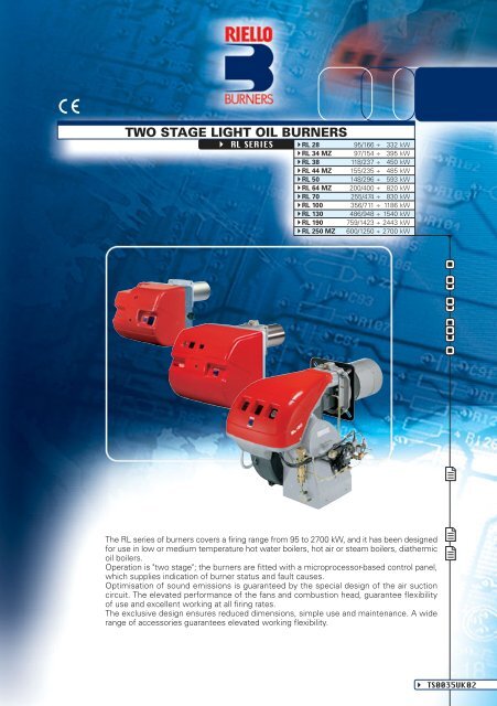
<strong>TWO</strong> <strong>STAGE</strong> <strong>LIGHT</strong> <strong>OIL</strong> <strong>BURNERS</strong><br />
RL SERIES<br />
RL 28 95/166 ÷ 332 kW<br />
RL 34 MZ 97/154 ÷ 395 kW<br />
RL 38 118/237 ÷ 450 kW<br />
RL 44 MZ 155/235 ÷ 485 kW<br />
RL 50 148/296 ÷ 593 kW<br />
RL 64 MZ 200/400 ÷ 820 kW<br />
RL 70 255/474 ÷ 830 kW<br />
RL 100 356/711 ÷ 1186 kW<br />
RL 130 486/948 ÷ 1540 kW<br />
RL 190 759/1423 ÷ 2443 kW<br />
RL 250 MZ 600/1250 ÷ 2700 kW<br />
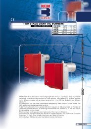
The RL series of burners covers a firing range from 95 to 2700 kW, and it has been designed<br />
for use in low or medium temperature hot water boilers, hot air or steam boilers, diathermic<br />
oil boilers.<br />
Operation is "two stage"; the burners are fitted with a microprocessor-based control panel,<br />
which supplies indication of burner status and fault causes.<br />
Optimisation of sound emissions is guaranteed by the special design of the air suction<br />
circuit. The elevated performance of the fans and combustion head, guarantee flexibility<br />
of use and excellent working at all firing rates.<br />
The exclusive design ensures reduced dimensions, simple use and maintenance. A wide<br />
range of accessories guarantees elevated working flexibility.<br />
TS0035UK02
Fuel / air data<br />
Electrical data<br />
Emissions<br />
Approval<br />
Model<br />
RL 28<br />
TECHNICAL DATA<br />
RL 34 MZ RL 38<br />
RL 44 MZ RL 50 RL 64 MZ<br />
Servomotor<br />
s<br />
kW<br />
95/166÷332<br />
148/296÷593<br />
Heat output<br />
Mcal/h 82/143÷286<br />
127/255÷510<br />
Kg/h<br />
8/14÷28<br />
12,5/25÷50<br />
°C min./max.<br />
Net calorific value<br />
kWh/kg<br />
Kcal/kg<br />
mm<br />
Pump<br />
AN 57C<br />
45<br />
AL 75C<br />
88<br />
(01)<br />
(01)<br />
(03)<br />
(09)<br />
(03)<br />
(03)<br />
0,37<br />
0,56<br />
0,75<br />
0,22<br />
0,11<br />
0,10<br />
44<br />
44<br />
0,25<br />
0,45<br />
0,65<br />
2,1<br />
2 - 1,2<br />
3 - 1,7<br />
4,8<br />
9,5 - 5,5<br />
13,8 - 8<br />
54<br />
54<br />
230V - 2x5kV<br />
230V - 2x5kV<br />
1,9A - 30mA<br />
1,9A - 30mA<br />
(10)<br />
(10)<br />
68<br />
75<br />
< 200<br />
< 200<br />
DIN 5G224/93<br />
DIN 5G226/93<br />
2 Burner operation mode<br />
Two stage<br />
Modulation ratio to max. output<br />
2 ÷ 1<br />
type<br />
--<br />
run time<br />
--<br />
97/154÷395 118/237÷450<br />
155/235÷485 200/400÷820<br />
83/133÷340 101/204÷387<br />
133/204÷418 172/344÷705<br />
8,3/13÷33,6 10/20÷38<br />
13/20÷41 17/38÷69<br />
Working temperature<br />
0/40<br />
11,8<br />
10200<br />
Viscosity at 20°C<br />
/s (cSt)<br />
4 ÷ 6<br />
type<br />
output kg/h at 12 bar<br />
AN 57C<br />
45<br />
AL 65C<br />
67<br />
AN 67C<br />
67<br />
AL 95C<br />
107<br />
Atomised pressure bar<br />
12<br />
Oil temperature Max. °C<br />
50<br />
Fan<br />
type<br />
(02) (01)<br />
(02) (02)<br />
Air temperature Max. °C<br />
60<br />
Electrical supply Ph/Hz/V<br />
(04) (03)<br />
(04) (06) (05)<br />
Auxiliary electrical supply Ph/Hz/V<br />
(04) (03)<br />
(04) (03)<br />
Control box<br />
type<br />
RMO 88.53<br />
Total electrical power kW<br />
0,6 0,6<br />
0,7 0,75 1,4<br />
Auxiliary electrical power kW<br />
0,3 0,18<br />
0,28 0,3 0,3<br />
Protection level IP<br />
2XD 44<br />
2XD 44<br />
Power electric motor kW<br />
0,3 0,42<br />
0,42 0,45 1,1<br />
Rated motor current A<br />
2,4 2,9<br />
3 2 - 1.2 4.7 - 2.7<br />
Motor start current A<br />
9,6 11<br />
12 9.5 - 5.5 24.5 - 14<br />
Motor protection level IP<br />
20 54<br />
44 55<br />
Ignition<br />
V1 - V2<br />
230V - 2x12kV 230V - 2x5kV<br />
230V - 2x12kV 230V - 2x5kV<br />
transformer<br />
I1 - I2<br />
0,2A - 30mA 1,9A - 30mA<br />
0,2A - 30mA 1,9A - 30mA<br />
Operation<br />
(11) (10)<br />
(11) (11)<br />
Sound pressure dBA<br />
70 70<br />
72 76<br />
Sound output W<br />
--<br />
CO emission<br />
mg/kWh<br />
< 40<br />
Grade of smoke indicator N° Bach.<br />
< 1<br />
CxHy emission mg/kWh<br />
Fuel / air data<br />
Electrical data<br />
Emissions<br />
Approval<br />
Model<br />
Servomotor<br />
s<br />
kW<br />
Heat output<br />
Mcal/h<br />
Kg/h<br />
°C min./max.<br />
kWh/kg<br />
Net calorific value<br />
Kcal/kg<br />
mm<br />
Pump<br />
2 Burner operation mode<br />
Modulation ratio to max. output<br />
type<br />
run time<br />
Working temperature<br />
Viscosity at 20°C<br />
type<br />
/s (cSt)<br />
output kg/h at 12 bar<br />
Atomised pressure bar<br />
Oil temperature Max. °C<br />
Fan<br />
type<br />
Air temperature Max. °C<br />
Electrical supply Ph/Hz/V<br />
Auxiliary electrical supply Ph/Hz/V<br />
Control box<br />
type<br />
Total electrical power kW<br />
Auxiliary electrical power kW<br />
Protection level IP<br />
Power electric motor kW<br />
Rated motor current A<br />
Motor start current A<br />
Motor protection level IP<br />
Ignition<br />
V1 - V2<br />
transformer<br />
Operation<br />
I1 - I2<br />
Sound pressure dBA<br />
Sound output W<br />
CO emission<br />
mg/kWh<br />
Grade of smoke indicator N° Bach.<br />
CxHy emission mg/kWh<br />
NOx emission<br />
Directive<br />
According to<br />
Certification<br />
mg/kWh<br />
RL 70<br />
255/474÷830<br />
219/408÷714<br />
21,5/40÷70<br />
AL 95C<br />
107<br />
(01)<br />
(09)<br />
(03)<br />
1,4<br />
0,3<br />
44<br />
1,1<br />
4,8 - 2,8<br />
25 - 14,6<br />
54<br />
230V - 2x5kV<br />
1,9A - 30mA<br />
(10)<br />
75<br />
< 200<br />
DIN 5G424/99<br />
RL 100<br />
356/711÷1186<br />
306/612÷1020<br />
30/60÷100<br />
AJ 6CC<br />
164<br />
RL 130<br />
Two stage<br />
2 ÷ 1<br />
--<br />
--<br />
486/948÷1540<br />
418/816÷1325<br />
41/80÷130<br />
0/40<br />
11,8<br />
10200<br />
4 ÷ 6<br />
AJ 6CC<br />
164<br />
12<br />
50<br />
(01)<br />
60<br />
(09)<br />
(03)<br />
RMO 88.53<br />
2,6<br />
0,4<br />
44<br />
2,2<br />
8,8 - 5,1<br />
57,2 - 33,2<br />
54<br />
230V - 2x5kV<br />
1,9A - 30mA<br />
(10)<br />
78,5<br />
--<br />
< 40<br />
< 1<br />
mm H 2 O<br />
mm H 2 O<br />
mm H 2 O<br />
100<br />
90<br />
80<br />
70<br />
60<br />
50<br />
40<br />
30<br />
20<br />
10<br />
0<br />
-10<br />
120<br />
110<br />
100<br />
90<br />
80<br />
70<br />
60<br />
50<br />
40<br />
30<br />
20<br />
10<br />
0<br />
-10<br />
180<br />
160<br />
140<br />
120<br />
100<br />
80<br />
60<br />
40<br />
20<br />
0<br />
-20<br />
hPa (mbar)<br />
hPa (mbar)<br />
hPa (mbar)<br />
10<br />
9<br />
8<br />
7<br />
6<br />
5<br />
4<br />
3<br />
2<br />
1<br />
0<br />
- 1<br />
0<br />
12<br />
11<br />
10<br />
9<br />
8<br />
7<br />
6<br />
5<br />
4<br />
3<br />
2<br />
1<br />
0<br />
-1<br />
18<br />
16<br />
14<br />
12<br />
10<br />
8<br />
6<br />
4<br />
2<br />
0<br />
-2<br />
0<br />
0<br />
Useful working field for choosing the burner<br />
1 st stage operating rate<br />
RL 34 MZ<br />
Test conditions conforming to EN 267:<br />
Temperature: 20°C<br />
Pressure: 1013.5 mbar<br />
Altitude: 100 m a.s.l.<br />
RL 38<br />
RL 44 MZ<br />
RL 28<br />
FIRING RATES<br />
10 20<br />
30<br />
40<br />
50<br />
60 kg/h<br />
100<br />
200 300 400 500 600 700 kW<br />
RL 64 MZ<br />
RL 70<br />
0 100<br />
300 500 700 900 1100 1300 1500<br />
1700<br />
RL 250 MZ<br />
RL 50<br />
RL 100<br />
RL 190<br />
RL 130<br />
10 30<br />
50<br />
70 90 110 130 150 kg/h<br />
50 70 90 110 130 150 170 190 210 230 250<br />
kg/h<br />
500 700 900 1100 1300 1500 1700 1900 2100 2300 2500 2700 2900<br />
4<br />
kW<br />
kW
HYDRAULIC CIRCUITS<br />
Example of adjustable hydraulic ram of<br />
RL 34 - 44 MZ burners<br />
RL 28 - 34 MZ<br />
P<br />
FUEL SUPPLY<br />
The burners are fitted with three<br />
valves (a safety valve and two oil<br />
delivery valves).<br />
RL 70 - 100 - 130 RL 190<br />
P<br />
VS<br />
RL 250 MZ<br />
P<br />
VF2 VF1<br />
VC<br />
MT<br />
VF2 VF1<br />
VS<br />
VC<br />
VF1<br />
MT<br />
VF2<br />
M<br />
SM<br />
AD<br />
AD<br />
AD<br />
A control device, on the basis of required output, regulates oil<br />
delivery valves opening, allowing light oil passage trough the<br />
valves and the nozzle.<br />
Delivery valves opening supplies the two-stage hydraulic ram<br />
which regulates air delivery in relation to the fuel burnt.<br />
The pumping group is fitted whit a pump, an oil filter and a<br />
regulating valve, that adjust atomised pressure.<br />
U1<br />
U2<br />
U1<br />
U2<br />
U2<br />
U1<br />
5<br />
RL 38 - 44 MZ - 50 - 64 MZ<br />
P<br />
VS<br />
P<br />
VS<br />
VF2 VF1<br />
VC<br />
MT<br />
VF2 VF1<br />
MT<br />
P Pump with filter and pressure regulator on the output<br />
circuit<br />
VS Safety valve on the output circuit<br />
VF1 1st stage valve<br />
VF2 2nd stage valve<br />
VC 2nd stage control device<br />
MT Hydraulic ram<br />
AD Air damper<br />
U1 1st stage nozzle<br />
U2 2nd stage nozzle<br />
AD<br />
AD<br />
U1<br />
U2<br />
U1<br />
U2
DIMENSIONING OF THE FUEL SUPPLY LINES<br />
The fuel feed must be completed with the safety devices required by the local norms.<br />
The table shows the choice of piping diameter for the various burners, depending on the difference<br />
in height between the burner and the tank and their distance.<br />
MAXIMUM EQUIVALENT LENGTH FOR THE PIPING L[m]<br />
Model<br />
RL 28 RL 38 - 50 RL 70 - 100 - 130 RL 190<br />
Diameter piping Ø10mm Ø12mm Ø14mm Ø10mm Ø12mm Ø14mm Ø12mm Ø14mm Ø16mm Ø16mm Ø18mm<br />
+H, -H (m) L max (m) L max (m) L max (m) L max (m) L max (m) L max (m) L max (m) L max (m) L max (m) L max (m) L max (m)<br />
+4,0 63 144 150 51 112 150 71 138 150 60 80<br />
+3,0 55 127 150 46 99 150 62 122 150 50 70<br />
+2,0 48 111 150 39 86 150 58 106 150 40 60<br />
+1,5 44 102 150 35 79 147 51 98 150 35 55<br />
+1,0 40 94 150 32 73 144 44 90 150 30 50<br />
+0,5 37 86 150 29 65 132 40 82 150 25 45<br />
0<br />
33 78 150 26 60 120 36 74 137 20 40<br />
-0,5 29 70 133 23 54 106 32 66 123 18 35<br />
-1,0 25 82 118 20 47 96 28 56 109 15 30<br />
-1,5 21 63 103 16 40 83 23 49 95 13 25<br />
-2,0 17 45 88 13 34 71 19 42 81 10 20<br />
-3,0 10 29 58 7 21 46 10 26 53 5 10<br />
-4,0<br />
4 12 28 2 8 21 3 10 25 3 6<br />
note<br />
6<br />
6<br />
7<br />
7<br />
10<br />
9 5 V<br />
10 cm<br />
8<br />
4<br />
+H<br />
-H<br />
5<br />
9<br />
P<br />
3<br />
2<br />
1<br />
H Difference in height pump-foot valve<br />
Ø Internal pipe diameter<br />
P Height 10 m<br />
V Height 4 m<br />
1 Burner<br />
2 Burner pump<br />
3 Filter<br />
4 Manual shut off valve<br />
5 Suction pipework<br />
6 Bottom valve<br />
7 Remote controlled rapid manual<br />
shut off valve<br />
(compulsory in Italy)<br />
8 Type approved shut off solenoid valve<br />
(compulsory in Italy)<br />
9 Return pipework<br />
10 Check valve<br />
With ring distribution oil systems, the feasible drawings and dimensioning are the responsibility<br />
of specialised engineering studios, who must check compatibility with the requirements and<br />
features of each single installation.<br />
6
Example of the air damper on<br />
RL 28 - 38 - 50 burners<br />
VENTILATION<br />
The ventilation circuit produces low<br />
noise levels with high performance<br />
pressure and air output, in spite of the<br />
compact dimensions.<br />
On RL 28-38-50-100-130 models, the use of reverse curve blades and<br />
sound proofing material keeps noise level very low.<br />
In the RL 34 MZ-44 MZ-64 MZ-190-250 MZ models, sound has been<br />
reduced by the special design of the air suction circuit.<br />
An hydraulic ram allows to have a right air flow in any operational<br />
moment and the closure of the air damper with burner in stand-by.<br />
The RL 34 MZ and RL 44 MZ are realised with a new structure made by an innovative technology<br />
based on a new fibreglass reinforced polyamide material, with high thermal and mechanical<br />
characteristics, instead of the traditional aluminium.<br />
This allows big advantages in terms of lay-out rationalisation, weight and dimensions reduction.<br />
In order to guarantee the correct<br />
exercise temperature for the<br />
internal burner components in<br />
every working conditions, the<br />
new structure includes an<br />
innovative patented cooling<br />
technology.<br />
Between the burner front base<br />
and the reinforcing steel front<br />
plate, had been create an air<br />
cavity offering an high thermal<br />
insulation against the front boiler<br />
reflection heat, and to further<br />
improve the insulation efficiency<br />
the innovative HCS (Housing<br />
Cooling System) technology<br />
had been developed. Inside the<br />
front base cavity an air<br />
circulation is activated with<br />
continuous air volume refresh to<br />
obtain an active cooling system<br />
and avoid any heat transfer to<br />
the electrical component<br />
Example of HCS (Housing Cooling System) working concept<br />
housing.<br />
7
COMBUSTION HEAD<br />
Different lengths of the<br />
combustion head can be chosen<br />
for the RL series of burners.<br />
The choice depends on the thickness of the front panel and the<br />
type of boiler.<br />
Depending on the type of generator, check that the penetration<br />
of the head into the combustion chamber is correct.<br />
The internal position of the combustion head can easily be adjusted<br />
to the maximum defined output by adjusting a screw fixed to the<br />
flange.<br />
Dimensions of the flame<br />
Lenght of the flame (m)<br />
4<br />
3<br />
2<br />
1<br />
L max<br />
L min<br />
D max<br />
D min<br />
0 0<br />
0 1 2<br />
3 4<br />
Burner output (MW)<br />
8<br />
2<br />
1,5<br />
1<br />
0,5<br />
Diameter of the flame (m)<br />
D<br />
L<br />
Example of a RL burner<br />
combustion head<br />
Example:<br />
Burner thermal output = 2000 kW;<br />
L flame (m) = 2,7 m (medium value);<br />
D flame (m) = 0,8 m (medium value)
BURNER OPERATION MODE<br />
Two stage operation<br />
ADJUSTMENT<br />
All RL series burners are fitted with a new microprocessor control panel for the supervision during<br />
intermittent operation.<br />
For helping the commissioning and maintenance work, there are two main elements:<br />
Switc<br />
Output Controlled variable<br />
Picture A<br />
°C<br />
bar<br />
MAX<br />
MIN<br />
The lock-out reset button is the central operating element for resetting the burner control<br />
and for activating / deactivating the diagnostic functions.<br />
The multi-color LED is the central indication element for visual diagnosis and interface<br />
diagnosis.<br />
Both elements are located under the transparent cover of lock-out reset button, as showed below.<br />
There are two diagnostic choices, for indication of operation and diagnosis of fault cause:<br />
- visual diagnosis :<br />
- interface diagnosis :<br />
time<br />
time<br />
INTERFACE ADAPTER<br />
With two stage operation, the RL<br />
burners can follow the temperature<br />
load requested by the system.<br />
A modulation ratio of 2:1 is reached, thanks to the “two nozzles”<br />
technique; the air is adapted to the hydraulic ram positions.<br />
On “two stage” operation, the burner gradually adjusts output<br />
to the requested level, by varying between the two pre-set levels<br />
(see picture A).<br />
9<br />
Switc<br />
COMPUTER<br />
or<br />
FLUE GAS<br />
ANALYSER<br />
by the interface adapter<br />
and a PC with dedicated<br />
software or by a<br />
predisposed flue gas<br />
analyzer (see paragraph<br />
accessories).
Indication of operation :<br />
In normal operation, the various status are<br />
indicated in the form of colour codes according<br />
to the table below.<br />
The interface diagnosis (with adapter) can be<br />
activated by pressing the lock-out button for<br />
> 3 seconds.<br />
Diagnosis of fault causes :<br />
After lock-out has occurred, the red signal lamp is steady on. In this status, the visual fault diagnosis<br />
according to the error code table can be activated by pressing the lock-out reset button for > 3 seconds.<br />
The interface diagnosis (with adapter) can be activated by pressing again the lock-out button for > 3<br />
seconds.<br />
The flashing of red LED are a signal with this sequence :<br />
(e.g. signal with n° 3 flashes – faulty air pressure monitor)<br />
LED off<br />
START UP CYCLE<br />
RL 28 - 34 MZ - 38 - 44 MZ - 50 - 64 MZ - 70 - 100 - 130 - 190 - 250 MZ<br />
Color code table<br />
Operation status<br />
Color code table<br />
Stand-by<br />
Pre-purging<br />
Ignition phase<br />
Flame OK<br />
Poor flame<br />
Undervoltage, built-in fuse<br />
Fault, alarm<br />
Extraneous light<br />
LED off<br />
3 sec. 3 sec. 3 sec.<br />
Error code table<br />
Possible cause of fault<br />
No establishment of flame at the end of safety time : - faulty or soiled fuel valves<br />
- faulty or soiled flame detector<br />
- poor adjustment of burner, no fuel<br />
- faulty ignition equipment<br />
Faulty air pressure monitor<br />
Extraneous light or simulation of flame on burner start up<br />
Loss of flame during operation : - faulty or soiled fuel valves<br />
- faulty or soiled flame detector<br />
- poor adjustment of burner<br />
Wiring error or internal fault<br />
RMO<br />
LED*<br />
TL<br />
TR<br />
M<br />
VF1<br />
VF2<br />
3<br />
2<br />
2°<br />
1° 2<br />
0<br />
2°<br />
1°<br />
0<br />
0 s<br />
22<br />
29<br />
36<br />
Off Yellow Green<br />
A<br />
A<br />
time (s)<br />
Flash code<br />
0 s The burner begins the firing cycle:<br />
the motor and transformer are<br />
supplied; the hydraulic ram opens<br />
in the pre-purge position.<br />
22÷29 s Ignition: the VS and VF1 valves<br />
are supplied.<br />
36 s If the control device TR is closed<br />
or has been replaced by a jumper<br />
wire, the 2 nd stage valve VF2<br />
opens; the fuel is sprayed out<br />
through the 2 nd stage nozzle and<br />
the hydraulic ram opens the air<br />
damper in the 2nd stage position.<br />
10<br />
2 flashes<br />
3 flashes<br />
4 flashes<br />
7 flashes<br />
10 flashes
Example of the terminal board<br />
for electrical connections on<br />
RL 28 - 38 burners<br />
BURNER WIRING<br />
All models of the RL burner series have an easily accessible control<br />
panel for the electrical components housing and wiring.<br />
In particular the new RL 34-44 MZ models, thanks to the new structure<br />
concept, have a extremely clean electrical layout to optimise the<br />
commissioning and maintenance speed.<br />
On these models the electrical connection are done by a Plug&Socket<br />
system, accessible from the external of the cover.<br />
The electrical wiring of all RL burner models are very easy to do<br />
following the wiring diagrams included in the instruction handbook.<br />
Electrical connections must be made by qualified and skilled personnel,<br />
according to the local norms.<br />
The following table shows the supply lead sections and the type of fuse to be used.<br />
Model<br />
F<br />
L<br />
A<br />
mm 2<br />
Model<br />
F<br />
L<br />
A<br />
mm 2<br />
RL 28 RL 34 MZ RL 38<br />
230V<br />
T6<br />
1,5<br />
230V<br />
T10<br />
1,5<br />
RL 70<br />
400V<br />
T6<br />
1,5<br />
230V<br />
T6<br />
1,5<br />
230V<br />
T16<br />
1,5<br />
230V<br />
T6<br />
1,5<br />
400V<br />
T6<br />
1,5<br />
RL 100 RL 130<br />
400V<br />
T10<br />
1,5<br />
230V<br />
T16<br />
1,5<br />
RL 44 MZ<br />
400V<br />
T10<br />
1,5<br />
11<br />
230V<br />
T6<br />
1,5<br />
230V<br />
T25<br />
2,5<br />
RL 44 MZ RL 50 RL 64 MZ<br />
230V<br />
T6<br />
1,5<br />
RL 190<br />
400V<br />
T25<br />
2,5<br />
400V<br />
T6<br />
1,5<br />
230V<br />
T6<br />
1,5<br />
400V<br />
T6<br />
1,5<br />
RL 250 MZ<br />
400V<br />
16A aM - 32A gG<br />
4<br />
230V<br />
T10<br />
1,5<br />
400V<br />
T6<br />
1,5<br />
Example of<br />
electrical<br />
components<br />
housing and<br />
Plug&Socket<br />
system for<br />
electrical<br />
connection of<br />
RL 34 - 44 MZ
mg/kWh<br />
mg/kWh<br />
dB(A)<br />
250<br />
200<br />
150<br />
100<br />
50<br />
0<br />
50<br />
40<br />
30<br />
20<br />
10<br />
0<br />
100<br />
80<br />
60<br />
40<br />
20<br />
0<br />
EMISSIONS<br />
NO2 EMISSIONS<br />
RL 28 RL 34 MZ RL 38 RL 44 MZ RL 50 RL 64 MZ RL 70 RL 100 RL 130 RL 190<br />
CO EMISSIONS<br />
NOISE EMISSIONS<br />
The emission data has been measured in the various models at maximum output, according to<br />
EN 267 standard.<br />
The NOx emissions of RL 34-44-64-250 MZ models are conforming to the class 2 of EN 267.<br />
RL 250 MZ<br />
RL 28 RL 34 MZ RL 38 RL 44 MZ RL 50 RL 64 MZ RL 70 RL 100 RL 130 RL 190 RL 250 MZ<br />
RL 28 RL 34 MZ RL 38 RL 44 MZ RL 50 RL 64 MZ RL 70 RL 100 RL 130 RL 190 RL 250 MZ<br />
12
D<br />
<strong>BURNERS</strong><br />
D<br />
A<br />
B C<br />
A<br />
RL 64 MZ<br />
OVERALL DIMENSIONS (mm)<br />
O - O (1)<br />
RL 34 - 44 MZ<br />
O - O (1)<br />
E<br />
E<br />
L<br />
F - F(1)<br />
H<br />
I<br />
H<br />
I<br />
D<br />
D<br />
A<br />
RL 28 - 38 - 50<br />
O - O (1)<br />
Model A D E F - F (1) H I L O -<br />
RL 28 476 474 468 216 - 351 140 352 52 672 -<br />
RL 34 MZ 442 422 508 216 - 351 140 305 138 780 -<br />
RL 38 476 474 468 216 - 351 140 352 52 672 -<br />
RL 44 MZ 442 422 508 216 - 351 152 305 138 780 -<br />
RL 50 476 474 468 216 -<br />
351 152 352 52 672 -<br />
(1) Length with extended combustion head<br />
F - F(1)<br />
RL 70 - 100 - 130 - 190 - 250 MZ<br />
B C E<br />
Model A B C D E F - F (1) H I<br />
RL 64 MZ 538 300 238 490 477 250 - 385 179 335<br />
RL 70 580 296 284 555 680 250 - 385 179 430<br />
RL 100 599 312 287 555 680 250 - 385 179 430<br />
RL 130 625 338 287 555 680 250 - 385 189 430<br />
RL 190 756 366 390 555 696 370 - - 222 430<br />
RL 250 MZ 910 432 478 596 705 378 - - 222 436<br />
(1) Length with extended combustion head<br />
L<br />
F - F(1)<br />
13<br />
A<br />
O - O (1)<br />
E<br />
L<br />
60<br />
-<br />
-<br />
-<br />
-<br />
-<br />
L<br />
O (1)<br />
807<br />
915<br />
807<br />
915<br />
807<br />
H<br />
F - F(1)<br />
O - O (1)<br />
680 - 545<br />
951 - 1086<br />
951 -1086<br />
951 -1086<br />
1102 - -<br />
1055 - -<br />
I<br />
H<br />
I
BURNER - B<strong>OIL</strong>ER MOUNTING FLANGE<br />
45°<br />
45°<br />
PACKAGING<br />
Z<br />
X (1)<br />
D1<br />
D2<br />
Ø<br />
Y<br />
14<br />
Model<br />
RL 28<br />
RL 34 MZ<br />
RL 38<br />
RL 44 MZ<br />
RL 50<br />
RL 64 MZ<br />
RL 70<br />
RL 100<br />
RL 130<br />
RL 190<br />
RL 250 MZ<br />
Model<br />
RL 28<br />
RL 34 MZ<br />
RL 38<br />
RL 44 MZ<br />
RL 50<br />
RL 64 MZ<br />
RL 70<br />
RL 100<br />
RL 130<br />
RL 190<br />
RL 250 MZ<br />
D1<br />
160<br />
160<br />
160<br />
160<br />
160<br />
185<br />
185<br />
185<br />
195<br />
230<br />
230<br />
D2 Ø<br />
224 M8<br />
224 M8<br />
224 M8<br />
224 M8<br />
224 M8<br />
275-325 M12<br />
275-325 M12<br />
275-325 M12<br />
275-325 M12<br />
325-368 M16<br />
325-368 M16<br />
X (1) Y Z kg<br />
1200<br />
1010<br />
1200<br />
1010<br />
1200<br />
1200<br />
1410<br />
1410<br />
1410<br />
1410<br />
1410<br />
(1) Length with short and extended head<br />
520<br />
520<br />
520<br />
520<br />
520<br />
560<br />
692<br />
692<br />
692<br />
985<br />
1040<br />
502<br />
510<br />
502<br />
510<br />
502<br />
520<br />
655<br />
655<br />
655<br />
655<br />
655<br />
36<br />
32<br />
38<br />
33<br />
39<br />
42<br />
60<br />
63<br />
66<br />
75<br />
140
INSTALLATION DESCRIPTION<br />
Installation, start up and maintenance must be carried out by<br />
qualified and skilled personnel.<br />
All operations must be performed in accordance with the<br />
technical handbook supplied with the burner.<br />
BURNER SETTING<br />
All the burners have slide bars, for easier installation and<br />
maintenance.<br />
After drilling the boilerplate, using the supplied gasket<br />
as a template, dismantle the blast tube from the burner<br />
and fix it to the boiler.<br />
Adjust the combustion head.<br />
Refit the burner casing to the slide bars.<br />
Install the nozzle, choosing this on the basis of the<br />
maximum boiler output and following the diagrams<br />
included in the burner instruction handbook.<br />
Check the position of the electrodes.<br />
Close the burner, sliding it up to the flange, keeping it<br />
slightly raised to avoid the flame stability disk rubbing<br />
against the blast tube.<br />
HYDRAULIC AND ELECTRICAL CONNECTIONS<br />
AND START UP<br />
The burners are supplied for connection to two pipes fuel<br />
supply system.<br />
Connect the ends of the flexible pipes to the suction and<br />
return pipework using the supplied nipples.<br />
Make the electrical connections to the burner following<br />
the wiring diagrams included in the instruction handbook.<br />
Prime the pump by turning the motor.<br />
On start up, check:<br />
- Pressure pump (to max. and min.)<br />
- Combustion quality, in terms of unburned substances<br />
and excess air.<br />
BURNER MAINTENANCE<br />
The maintenance of RL burners is very simple thanks to<br />
the sliding bars system that allows an easy access to the<br />
internal components.<br />
In particular the RL 34-44 MZ models have a new sliding<br />
bars system to make easier the access to the combustion<br />
head.<br />
The RL 190 and RL 250 MZ have new reinforced sliding<br />
bars that make very strong the burner structure during<br />
maintenance.<br />
15
BURNER ACCESSORIES<br />
Nozzles<br />
The nozzles must be ordered separately. The following table shows the<br />
features and codes on the basis of the maximum required fuel output.<br />
Nozzles type 60° B<br />
Burner GPH Rated output (kg/h) Nozzle<br />
at 10 bar at 12 bar at 14 bar code<br />
RL 34 MZ 1,00 4,1 4,5 4,9 3042077<br />
RL 34 MZ 1,25 4,7 5,2 5,6 3042096<br />
RL 34 - 44 MZ 1,50 5,7 6,3 6,8 3042107<br />
RL 34 - 44 MZ 1,75 6,7 7,3 7,9 3042110<br />
RL 28 - 34 MZ - 44 MZ 2,00 7,7 8,5 9,2 3042126<br />
RL 28 - 34 MZ - 38 - 44 MZ 2,50 9,6 10,6 11,5 3042140<br />
RL 28 - 34 MZ - 38 - 44 MZ - 50 3,00 11,5 12,7 13,8 3042158<br />
RL 28 - 34 MZ - 38 - 44 MZ - 50 3,50 13,5 14,8 16,1 3042162<br />
RL 34 MZ - 38 - 44 MZ - 50 - 64 MZ 4,00 15,4 17 18,4 3042172<br />
RL 34 MZ - 38 - 44 MZ - 50 - 64 MZ 4,50 17,3 19,1 20,7 3042182<br />
RL 38 - 44 MZ - 50 - 64 MZ - 70 5,00 19,2 21,2 23 3042192<br />
RL 44 MZ - 50 - 64 MZ - 70 5,50 21,1 23,3 25,3 3042202<br />
RL 44 MZ - 50 - 64 MZ - 70 6,00 23,1 25,5 27,7 3042212<br />
RL 50 - 64 MZ - 70 6,50 25 27,6 30 3042222<br />
RL 64 MZ - 70 - 100 7,00 26,9 29,7 32,3 3042232<br />
RL 64 MZ - 70 - 100 7,50 28,8 31,8 34,6 3042242<br />
RL 64 MZ - 70 - 100 8,00 30,8 33,9 36,9 3042252<br />
RL 64 MZ - 70 - 100 8,50 32,7 36,1 39,2 3042262<br />
RL 64 MZ - 70 - 100 - 130 9,50 36,5 40,3 43,8 3042282<br />
RL 64 MZ - 70 - 100 - 130 - 190 10,00 38,4 42,4 46,1 3042292<br />
RL 64 MZ - 70 - 100 - 130 - 190 11,00 42,3 46,7 50,7 3042312<br />
RL 64 MZ - 100 - 130 - 190 - 250 MZ 12,00 46,1 50,9 55,3 3042322<br />
RL 64 MZ - 100 - 130 - 190 - 250 MZ 13,00 50 55,1 59,9 3042332<br />
RL 64 MZ - 100 - 130 - 190 - 250 MZ 14,00 53,8 59,4 64,5 3042352<br />
RL 64 MZ - 100 - 130 - 190 - 250 MZ 15,00 57,7 63,6 69,2 3042362<br />
RL 64 MZ - 100 - 130 - 190 - 250 MZ 16,00 61,5 67,9 73,8 3042382<br />
RL 64 MZ - 130 - 190 - 250 MZ 17,00 65,4 72,1 78,4 3042392<br />
RL 130 - 190 - 250 MZ 18,00 69,2 76,4 83 3042412<br />
RL 130 - 190 - 250 MZ 19,00 73 80,6 87,6 3042422<br />
RL 130 - 190 - 250 MZ 20,00 76,9 84,8 92,2 3042442<br />
RL 190 - 250 MZ 22,00 84,6 93,3 101,4 3042462<br />
RL 190 - 250 MZ 24,00 92,2 101,8 110,6 3042472<br />
RL 190 - 250 MZ 26,00 99,9 110,3 119,9 3042482<br />
RL 190 - 250 MZ 28,00 107,6 118,8 129,1 3042492<br />
RL 250 MZ 30,00 110,4 122 132,4 3042502<br />
RL 250 MZ 32,00 117,8 130,1 150,1 3042512<br />
RL 250 MZ 35,00 128,8 142,1 154,5 3042522<br />
16
Extended heads<br />
“Standard head” burners can be transformed into “extended head” versions, by using the special<br />
kit. The kits available for the various burners, giving the original and the extended lengths, are listed<br />
below.<br />
Combustion head extension kits<br />
Burner ‘Standard’<br />
head length (mm)<br />
‘Extended’<br />
head length (mm)<br />
RL 28<br />
216<br />
351<br />
RL 34 MZ<br />
216<br />
351<br />
RL 38<br />
216<br />
351<br />
RL 44 MZ<br />
216<br />
351<br />
RL 50<br />
216<br />
351<br />
RL 64 MZ<br />
250<br />
385<br />
RL 70<br />
250<br />
385<br />
RL 100<br />
250<br />
385<br />
RL 130<br />
250<br />
385<br />
RL 190<br />
370<br />
530<br />
RL 250 MZ<br />
378<br />
528<br />
Spacer kit<br />
If burner head penetration into the combustion chamber needs reducing, varying thickness spacers<br />
are available, as given in the following table:<br />
S<br />
Burner<br />
Head length reduction kit<br />
Spacer thickness S (mm)<br />
RL 28 - 34 MZ - 38 - 44 MZ - 50<br />
90<br />
RL 64 MZ - 70 - 100 - 130<br />
135<br />
RL 190 - 250 MZ<br />
110<br />
Kit code<br />
3010073<br />
3010426<br />
3010074<br />
3010425<br />
3010075<br />
3010114<br />
3010114<br />
3010115<br />
3010116<br />
3010444<br />
3010422<br />
Kit code<br />
3010095<br />
3010129<br />
3000722<br />
Sound proofing box<br />
If noise emission needs reducing even further, sound-proofing boxes are available, as given in the<br />
following table:<br />
Burner<br />
Sound proofing box<br />
Box type Average noise<br />
RL 28 - 34 MZ - 38 - 44 MZ<br />
RL 50 - 64 MZ - 70 - 100 - 130 C1/3<br />
reduction [dB(A)](*)<br />
10<br />
RL 190 - 250 MZ<br />
(*) according to EN 15036-1 standard<br />
17<br />
C4/5<br />
10<br />
Box code<br />
3010403<br />
3010404
Degasing unit<br />
With single pipe systems, you can find air in the oil sucked by the pump that comes from the oil itself<br />
due to negative pressure or to a faulty seal.<br />
To solve this problem, we recommend fitting a degasing unit near the burner. Two versions are<br />
available with or without filter:<br />
Degasing unit<br />
Burner Degasing unit with filter<br />
Code<br />
RL 28 - 34 MZ - 38<br />
RL 44 MZ - 50 - 64 MZ<br />
RL 70 - 100 - 130<br />
3010055<br />
RL 190 - 250 MZ<br />
Biodiesel kit<br />
For burning Biodiesel fuel, a special kit is available.<br />
RL 28<br />
RL 38<br />
RL 50<br />
RL 70<br />
RL 100<br />
RL 130<br />
RL 190<br />
18<br />
Degasing unit without filter<br />
Code<br />
3010054<br />
Biodiesel kit<br />
Burner Kit code<br />
Connection flange kit<br />
A kit is available for use where the burner opening on the boiler is of excessive diameter.<br />
Connection flange kit<br />
Burner<br />
RL 28 - 34 MZ - 38 - 44 MZ - 50<br />
3010289<br />
3010290<br />
3010291<br />
3010292<br />
3010358<br />
3010358<br />
-<br />
Kit code<br />
3010138<br />
Status Panel kit<br />
The RL burners can be equipped with an exclusive electronic device “Status Panel” which continuously<br />
monitors and displays all the burner operational modes and picks up any anomalies during the<br />
operational cycle.<br />
Status Panel kit<br />
Burner Kit code<br />
RL 28 - 38 - 50 - 70 - 100 - 130 - 190 - 250 MZ<br />
3010322<br />
RL 64 MZ<br />
3010321
Volt free contact kit<br />
A volt free contact kit is available for installation onto the burner. This can be used for a remote<br />
interface between burner operating signals, for example, burner run or lockout indication.<br />
Burner<br />
RL 34 MZ - 44 MZ<br />
PC interface kit<br />
To connect the flame control panel to a personal computer for the transmission of operation, fault<br />
signals and detailed service information, an interface adapter with PC software are available.<br />
Burner<br />
RL 28 - 34 MZ - 38 - 44 MZ - 50 - 64 MZ<br />
RL 70 - 100 - 130 - 190 - 250 MZ<br />
19<br />
Volt free contact kit<br />
PC interface kit<br />
Kit code<br />
3010419<br />
Kit code<br />
3002719
DESIGNATION OF SERIES R <strong>BURNERS</strong><br />
Series : R<br />
Fuel : S Natural Gas<br />
SP LPG<br />
L Light oil<br />
LS Light oil/Methane<br />
N Heavy oil<br />
Size<br />
SPECIFICATION<br />
A specific index guides your choice of burner from<br />
the various models available in the RL series.<br />
Below is a clear and detailed specification description<br />
of the product.<br />
Setting : /1 Single stage<br />
... Two stage<br />
/M Modulating<br />
Emission : ... Class 1 EN267 - EN676<br />
MZ Class 2 EN267 - EN676<br />
BLU Class 3 EN267 - EN676<br />
MX<br />
Class 1 EN267<br />
Class 3 EN676<br />
Head : TC Standard head<br />
TL Extended head<br />
Flame control system:<br />
FS1 Standard (1 stop every 24 h)<br />
FS2 Continuous working (1 stop every 72 h)<br />
R L 50 TC FS1 3/230-400/50 230/50-60<br />
BASIC DESIGNATION<br />
EXTENDED DESIGNATION<br />
20<br />
Electrical supply to the system :<br />
1/230/50 1/230V/50Hz<br />
1/220-230/50-60 1/220-230V/50-60Hz<br />
3/230/50 3/230V/50Hz<br />
3/400/50 3N/400V/50Hz<br />
3/230-400/50 3/230V/50Hz - 3N/400V/50Hz<br />
3/220/60 3/220V/60Hz<br />
3/380/60 3N/380V/60Hz<br />
3/220-380/60 3/220V/60Hz - 3N/380V/60Hz<br />
3/220-400/50-60<br />
3/220-230V/50-60Hz<br />
3/380-400V/50-60Hz<br />
Auxiliary voltage :<br />
230/50-60 230V/50-60Hz<br />
220-230/50-60 220-230V/50-60Hz<br />
110/50-60 110V/50-60Hz<br />
ID:<br />
Differential switch
LIST OF AVAILABLE MODELS<br />
RL 28 TC FS1 1/230/50 230/50-60<br />
RL 28 TL FS1 1/230/50 230/50-60<br />
RL 28 TC FS1 1/230/50 230/50-60<br />
RL 28 TL FS1 1/230/50 230/50-60<br />
RL 28 TC FS1 1/220-230/60 230/50-60<br />
RL 28 TL FS1 1/220-230/60 230/50-60<br />
RL 34 MZ TC FS1 1/220-230/50/60 220-230/50-60<br />
RL 34 MZ TL FS1 1/220-230/50/60 220-230/50-60<br />
RL 38 TC FS1 1/230/50 230/50-60<br />
RL 38 TL FS1 1/230/50 230/50-60<br />
RL 38 TC FS1 1/230/50 230/50-60<br />
RL 38 TL FS1 1/230/50 230/50-60<br />
RL 38 TC FS1 1/220/230/60 230/50-60<br />
RL 38 TL FS1 1/200/230/60 230/50-60<br />
RL 38 TC FS1 3/230/400/50 230/50-60<br />
RL 38 TL FS1 3/230/400/50 230/50-60<br />
RL 38 TC FS1 3/230/400/50 230/50-60<br />
RL 38 TL FS1 3/230/400/50 230/50-60<br />
RL 38 TC FS1 3/220-230/380-400/60 230/50-60<br />
RL 38 TL FS1 3/220-230/380-400/60 230/50-60<br />
RL 38 TC FS1 3/254-265/440-460/60 230/50-60<br />
RL 38 TL FS1 3/254-265/440-460/60 230/50-60<br />
RL 44 MZ TC FS1 1/220-230/50/60 220-230/50-60<br />
RL 44 MZ TL FS1 1/220-230/50/60 220-230/50-60<br />
RL 44 MZ TC FS1 3/220-400/50/60 220-230/50-60<br />
RL 44 MZ TL FS1 3/220-400/50/60 220-230/50-60<br />
RL 50 TC FS1 3/230-400/50 230/50-60<br />
RL 50 TL FS1 3/230-400/50 230/50-60<br />
RL 50 TC FS1 3/230-400/50 230/50-60<br />
RL 50 TL FS1 3/230-400/50 230/50-60<br />
RL 50 TC FS1 3/220-230/380-400/60 230/50-60<br />
RL 50 TL FS1 3/220-230/380-400/60 230/50-60<br />
RL 50 TC FS1 3/254-265/440-460/60 230/50-60<br />
RL 50 TL FS1 3/254-265/440-460/60 230/50-60<br />
RL 64 MZ TC FS1 3/230-400/50 230/50-60<br />
RL 64 MZ TL FS1 3/230-400/50 230/50-60<br />
RL 70 TC FS1 3/230-400/50 230/50-60<br />
RL 70 TL FS1 3/230-400/50 230/50-60<br />
RL 70 TC FS1 3/230-400/50 230/50-60<br />
RL 70 TL FS1 3/230-400/50 230/50-60<br />
RL 70 TC FS1 3/220-230/380-400/60 230/50-60<br />
RL 70 TL FS1 3/220-230/380-400/60 230/50-60<br />
RL 70 TC FS1 3/254-265/440-460/60 230/50-60<br />
RL 70 TL FS1 3/254-265/440-460/60 230/50-60<br />
RL 100 TC FS1 3/230-400/50 230/50-60<br />
RL 100 TL FS1 3/230-400/50 230/50-60<br />
RL 100 TC FS1 3/230-400/50 230/50-60<br />
RL 100 TL FS1 3/230-400/50 230/50-60<br />
RL 100 TC FS1 3/220-230/380-400/60 230/50-60<br />
RL 100 TL FS1 3/220-230/380-400/60 230/50-60<br />
RL 100 TC FS1 3/254-265/440-460/60 230/50-60<br />
RL 100 TL FS1 3/254-265/440-460/60 230/50-60<br />
RL 130 TC FS1 3/230-400/50 230/50-60<br />
RL 130 TL FS1 3/230-400/50 230/50-60<br />
RL 130 TC FS1 3/230-400/50 230/50-60<br />
RL 130 TL FS1 3/230-400/50 230/50-60<br />
RL 130 TC FS1 3/220-230/380-400/60 230/50-60<br />
RL 130 TL FS1 3/220-230/380-400/60 230/50-60<br />
RL 130 TC FS1 3/254-265/440-460/60 230/50-60<br />
RL 130 TL FS1 3/254-265/440-460/60 230/50-60<br />
RL 190 TC FS1 3/230-400/50 230/50-60<br />
RL 190 TC FS1 3/220-230/380-400/60 230/50-60<br />
RL 190 TC FS1 3/254-265/440-460/60 230/50-60<br />
RL 250 MZ TC FS1 3/400/50 230/50-60<br />
Other versions are available on request.<br />
21
PRODUCT SPECIFICATION<br />
RL 28 - 38 - 50 - 64 MZ - 70 - 100 - 130 - 190 - 250 MZ models<br />
Burner:<br />
Monoblock forced draught oil burner with two stage operation, fully automatic, made up of:<br />
- Air suction circuit lined with sound-proofing material<br />
- Fan with reverse curve blades (RL 28 - 38 - 50 - 70 - 100 - 130 models) or straight blades (RL 64<br />
MZ - 190 - 250 MZ models)<br />
- Air damper for air setting controlled by an adjustable hydraulic ram (or by a servomotor for the<br />
RL 250 MZ)<br />
- Starting motor at 2800 rpm, three-phase 400V with neutral, 50Hz (single-phase, 230V and 50Hz<br />
for the 28 - 38 models)<br />
- Combustion head, that can be set on the basis of required output, fitted with:<br />
- stainless steel end cone, resistant to corrosion and high temperatures<br />
- ignition electrodes<br />
- flame stability disk<br />
- Gears pump for high pressure fuel supply, fitted with:<br />
- filter<br />
- pressure regulator<br />
- connections for installing a pressure gauge and vacuometer<br />
- internal by-pass for single pipe installation<br />
- Valve unit with an oil safety valve and two delivery oil valves on the output circuit<br />
- Photocell for flame detection<br />
- Microprocessor-based flame control panel, with diagnostic function<br />
- Burner on/off switch<br />
- Flame inspection window<br />
- 1 st - 2 nd stage manual switch<br />
- Slide bars for easier installation and maintenance<br />
- Protection filter against radio interference<br />
- IP 44 electric protection level.<br />
Conforming to:<br />
- 89/336/EEC directive (electromagnetic compatibility)<br />
- 73/23/EEC directive (low voltage)<br />
- 92/42/EEC directive (performance)<br />
- 98/37/EEC directive (machinery)<br />
- EN 267 (liquid fuel burners).<br />
Standard equipment:<br />
- 2 flexible pipes for connection to the oil supply network<br />
- 2 gaskets for the flexible pipes<br />
- 2 nipples for connection to the pump<br />
- 4 screws for fixing the burner flange to the boiler<br />
- 1 thermal screen<br />
- Fairleads for electrical connections (RL 28 - 38 - 50 models)<br />
- 2 slide bar extensions (for the extended head models and the RL 190 - 250 MZ models)<br />
- Instruction handbook for installation, use and maintenance<br />
- Spare parts catalogue.<br />
Available accessories to be ordered separately:<br />
- Nozzles<br />
- Head extension kit<br />
- Head length reduction kit<br />
- Sound-proofing box<br />
- Degasing unit (with or without filter)<br />
- Biodiesel kit<br />
- Connection flange kit<br />
- Status panel kit<br />
- PC interface kit.<br />
22
PRODUCT SPECIFICATION<br />
RL 34 MZ - 44 MZ models<br />
Burner:<br />
Monoblock forced draught oil burner with two stage operation, fully automatic, made up of:<br />
- Air suction circuit<br />
- High performance fan with straight blades<br />
- Air damper for air setting controlled by an adjustable hydraulic ram<br />
- Starting motor at 2800 rpm, single-phase / 220-230V / 50-60Hz or three-phase 380-400V / 50-60Hz<br />
- Combustion head, that can be set on the basis of required output, fitted with:<br />
- stainless steel end cone, resistant to corrosion and high temperatures<br />
- ignition electrodes<br />
- flame stability disk<br />
- Exclusive patented HCS (Housing Cooling System) with high thermal insulation and air circulation<br />
with continuous air volume refresh for an active cooling system and avoid heat transfer to the<br />
electrical component housing<br />
- Gears pump for high pressure fuel supply, fitted with:<br />
- filter<br />
- pressure regulator<br />
- connections for installing a pressure gauge and vacuometer<br />
- internal by-pass for single pipe installation<br />
- Valve unit with an oil safety valve and two delivery oil valves on the output circuit<br />
- Photocell for flame detection<br />
- Microprocessor-based flame control panel, with diagnostic function<br />
- Plugs and Sockets for electrical connection, accessible from the external of the cover<br />
- Burner on/off switch<br />
- Flame inspection window<br />
- 1 st - 2 nd stage manual switch<br />
- Slide bars for easier installation and maintenance<br />
- Protection filter against radio interference<br />
- IP 44 electric protection level.<br />
Conforming to:<br />
- 89/336/EEC directive (electromagnetic compatibility)<br />
- 73/23/EEC directive (low voltage)<br />
- 92/42/EEC directive (performance)<br />
- 98/37/EEC directive (machinery)<br />
- EN 267 (liquid fuel burners).<br />
Standard equipment:<br />
- 2 flexible pipes for connection to the oil supply network<br />
- 2 gaskets for the flexible pipes<br />
- 2 nipples for connection to the pump<br />
- 4 screws for fixing the burner flange to the boiler<br />
- 1 thermal screen<br />
- 2 Plugs for electrical connection (RL 34-44 MZ single-phase)<br />
- 3 Plugs for electrical connection (RL 44 MZ three-phase)<br />
- 2 slide bar extensions (for the extended head models)<br />
- Instruction handbook for installation, use and maintenance<br />
- Spare parts catalogue.<br />
Available accessories to be ordered separately:<br />
- Nozzles<br />
- Head extension kit<br />
- Head length reduction kit<br />
- Sound-proofing box<br />
- Degasing unit (with or without filter)<br />
- Biodiesel kit<br />
- Connection flange kit<br />
- Status panel kit<br />
- Volt free contact kit<br />
- PC interface kit.<br />
23
ISO 9001 Cert. n. 0061<br />
RIELLO S.p.A. - Via Ing. Pilade Riello, 5 - 37045 Legnago (VR) Italy<br />
Tel. ++39.0442630111 - Fax ++39.044221980<br />
Internet: http://www.rielloburners.com - E-mail: info@rielloburners.com<br />
Since the Company is constantly engaged in the production improvement, the aesthetic and<br />
dimensional features, the technical data, the equipment and the accessories can be changed.<br />
This document contains confidential and proprietary information of RIELLO S.p.A.<br />
Unless authorised, this information shall not be divulged, nor duplicated in whole or in part.<br />
Lineagrafica.it