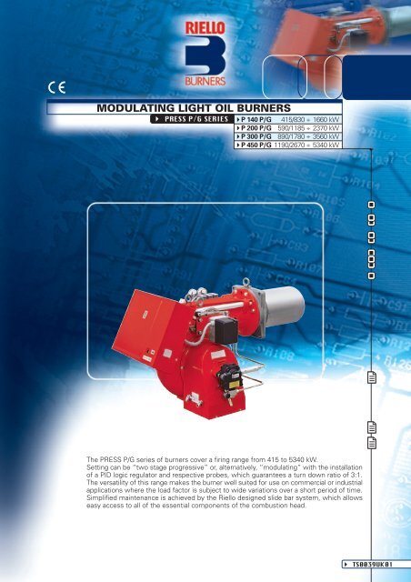
MODULATING LIGHT OIL BURNERS
MODULATING LIGHT OIL BURNERS
MODULATING LIGHT OIL BURNERS
- No tags were found...

Create successful ePaper yourself
Turn your PDF publications into a flip-book with our unique Google optimized e-Paper software.
TECHNICAL DATAModelP 140 P/GP 200 P/GP 300 P/GP 450 P/GBurner operation modeModulating (with regulator and probes accessories) or Two-stage progressiveModulation ratio at max. output3 ÷ 1Servomotor.run timetypesSQM 1042kW415/830÷1660590/1185÷2370890/1780÷35601190/2670÷5340Heat outputMcal/h357/714÷1428507/1019÷2038765/1531÷30621023/2296÷4592kg/h35/70÷14050/100÷20075/150÷300100/225÷450Working temperature°C min./max.0/40Fuel / air dataNet calorific valueViscosityPumpdeliveryAtomised pressureFuel temperaturekWh/kgkcal/kgmm 2 /s (cSt)typekg/hbarmax. °CTA2330 (25 bar)11,86102004 ÷ 6 (at 20°C)TA3TA4520 (25 bar)700 (25 bar)2550TA5880 (25 bar)Fuel pre-heaterNOFantypeCentrifugal with forward curve bladesAir temperaturemax. °C60Electrical supplyPh/Hz/V3N/50/400-230 (±10%) or 3/50/230 (±10%)Auxiliary electrical supplyPh/Hz/V1/50/230 (±10%)Control boxtypeLAL 1.25Total electrical powerkW4,55,51015Auxiliary electrical powerkW1,51,52,53Heaters electrical powerkW--Protection levelIP40Electrical dataPump motor electrical powerRated pump motor currentPump motor start up currentPump motor protection levelFan motor electrical powerkWAAIPkW34--------7,512Rated fan motor currentA8/13,59,5/16,417,5/3026/45Fan motor start up currentA51/8648/83113/195151/261Fan motor protection levelIP55typeIgnition transformerV1 - V2230 V - 2x6 kVI1 - I22,3 A - 35 mAOperationIntermittent (at least one stop every 24h)Sound pressuredB (A)86,585,589,590EmissionsSound powerCO emissionGrade of smoke indicatorCxHy emissionWmg/kWhN° Bacharachmg/kWh--< 35< 0,6< 8 (after the first 20 seconds)NOx emissionmg/kWh< 200< 200< 200< 220ApprovalDirectiveConforming toCertification89/336 - 73/23 - 92/42 - 98/37 EECEN 267DIN 5G459/2000 DIN 5G460/2000 DIN 5G461/200089/336-73/23-98/37 EECDIN 5G462/2000Reference conditions:Temperature: 20°CPressure: 1013,5 mbarAltitude: 100 m a.s.l.Noise measured at a distance of 1 meter.Since the Company is constantly engaged in the production improvement, the aesthetic and dimensional features, thetechnical data, the equipment and the accessories can be changed.This document contains confidential and proprietary information of RIELLO S.p.A. Unless authorised, this information shallnot be divulged, nor duplicated in whole or in part.
FIRING RATES1801816016P 300 P/GP 450 P/G14014P 200 P/GP 140 P/G1201210010808606404mm H 2O200hPa (mbar)20050 100 150 200 250 300 350 400 450kg/h05001000 1500 2000 2500 3000 3500 4000 45005000kWUseful working field for choosing the burnerModulation rangeTest conditions conforming to EN 267:Temperature: 20°CPressure: 1013.5 mbarAltitude: 100 m a.s.l.
FUEL SUPPLYHYDRAULIC CIRCUITVarious hydraulic circuit are available, depending on fuel outputasset according to local norms of steam generators.The burners are fitted with two valves (a safety valve andan operation valve) and an oil filter along the oil line fromthe pump to the nozzle.A pressure regulator on the return circuit from the nozzleallows to vary the quantity of fuel burnt.A double safety valve on the return circuit avoids oil leakagefrom the nozzle when the burner is in stand-by and prepurgephase.The models are fitted with a maximum pressure switch onthe oil return circuit.Example of the hydraulic circuit on PRESS 200 P/GEN 267 > 100 kg/hPFOVS VFVR1 VRPOmaxM SMROMRUPFOVSVFUMRSMROPO maxVRVR1Pump with filter and pressureregulator on the output circuitOil filterSafety valve on the output circuitWorking valve on the output circuitNozzlePressure gauge on the return circuitServomotorPressure regulator on the returncircuitMax. Oil pressure switch on thereturn circuit1st safety valve on the return circuit2nd safety valve on the return circuit
SELECTING THE FUEL SUPPLY LINESThe fuel feed must be completed with the safety devices required by the local norms.The table shows the choice of piping diameter for the various burners, depending on the differencein height between the burner and the tank and their distance.ModelDiameter piping+H, -H (m)+2,0+1,5+1,0+0,50-0,5-1,0-1,5-2,0-3,0MAXIMUM EQUIVALENT LENGTH FOR THE PIPING L[m]P 140 P/GP 200 P/GP 300 P/GØ14mmL max (m)5045403530252015105Ø16mmL max (m)70656050454035302515Ø16mmL max (m)4035302520181513105Ø18mmL max (m)60555045403530252010Ø1/2”L max (m)25232018151210853Ø 3/4”L max (m)85807065605045353015P 450 P/GØ 3/4” Ø1”L max (m) L max (m)55 13050 12045 11040 10035903080257020601545102567109 5 VP+H10 cm847 5 3921H Difference in height pump-foot valveØ Internal pipe diameterP Max. height 10 mV Height 4 m1 Burner2 Burner pump3 Filter4 Manual shut off valve5 Suction pipework6 Bottom valve7 Remote controlled rapid manualshut off valve(compulsory in Italy)8 Type approved shut off solenoid valve(compulsory in Italy)9 Return pipework10 Check valve-H6noteWith ring distribution oil systems, the feasible drawings and dimensioning are the responsibilityof specialised engineering studios, who must check compatibility with the requirements andfeatures of each single installation.
VENTILATIONThe ventilation circuit is provided with a forward blades centrifugalfan, which guarantees high pressurelevels at the required air deliveries andpermits installation flexibility.In spite of the remarkable output powerand of the very high pressure performances, structuresof PRESS models are extremely compact.The use of sound proofing boxes help in reducing thenoise level.A variable profile cam connects fuel and air setting,ensuring fuel efficiency in all firing rates.Example of servomotor forair/light oil settingCOMBUSTION HEADTwo different lenghts of the combustion head can be chosen forthe various models of the PRESS P/Gseries of burners.The choice depends on the thickness ofthe front panel and the type of the boiler.Depending on the type of heat generator, it is necessaryto check the correct head penetration into the combustionchamber.These burners are equipped with a variable geometrycombustion head. The chance to control air speed incombustion head is essential to gain the full advantageof a modulating burner. This function allows optimumcombustion performance throught the working field,ensuring peak combustion efficiency thus saving on fuelconsumption.The following diagram shows the flame dimensions inrelation to the burner output. The lenght and diametershown in the diagram below should be employedfor a preliminary check: it is required a more careful investigation if combustionchamber dimensions are much different from the above reported values.Flame dimensionsExample of a PRESS P/G burnercombustion head74Flame lenght (m)65432100 1 2 3L maxL minD maxD min3,532,521,510,504 5 6 7 8 9 10Burner output (MW)Flame diameter (m)DLExample:Burner thermal output = 3500 kW;L flame (m) = 3,5 m (medium value);D flame (m) = 1 m (medium value)
“<strong>MODULATING</strong>” OPERATION - pressure probeDirect start-up versionP 140-200-300 P/GStar delta start-up versionP 300-450 P/GRWF 40RWF 40Q13 Q14 G- G+ Q Y1Y2 L1 N M1 I1G1+ TEQ13 Q14 G- G+ Q Y1 Y2 L1 N M1 I1G1+TEMB L1 L2 L3 N L N 1 2 3 4 W1W2Q Y2 Y1 L N M B1 GFT6ATSPSI1BP1 24/20mAMB 35 36 37 38 39 40 41 42 43 44 LN 1 2 3 4 W1W2Q Y2 Y1 L N M B1 GTSPHS2T6ASI1BP1 24/20mALPE L1 L2 L3 N3N~50Hz 400/230V3~ 50Hz 230VM3~L N~ 50Hz 230VMB - Burner terminal boardL - Lead section (see table A)TS - Safety thermostatS - External lock-out signalRWF 40 - Regulator (fitted tothe burner)BP - Pressure probeT6A - 6A fuseF - Fuse (see table A)I1 - Manual switch1 2 3 4 35 36 37 38 39 40 41 42 43 44 45 5 6PE L1 L2 L3 NFL3N~50Hz 400/230V3~ 50Hz 230VM3~MAMB - Burner terminal boardL, H - Lead section (see table A)TS - Safety thermostatS, S2 - External lock-out signalRWF 40 - Regulator (fitted to theburner)BP - Pressure probeT6A - 6A fuseF - Fuse (see table A)MA - Star delta starterI1 - Manual switchThe following table showsthe supply lead sectionsand the type of fuse to beused.ModelFLHAmm 2mm 2P 140 P/G230VT252,5-400VT252,5-DirectP 200 P/G230VT354-400VT252,5-P 300 P/G230VT636-400VT504-P 300 P/G230VT5064Star delta400VT3542,5P 450 P/G230VT63106400VT5064Table AEMISSIONSmg/kWh250200NOx EMISSIONS150100500P 140 P/G P 200 P/G P 300 P/G P 450 P/Gmg/kWh5040CO EMISSIONSdB(A)10080NOISE EMISSIONS30602040102000P 140 P/G P 200 P/G P 300 P/G P 450 P/G P 140 P/G P 200 P/G P 300 P/G P 450 P/GThe emission data has been measured in the various models at maximum output, according toEN 267 standard.
OVERALL DIMENSIONS (mm)BURNERAEF - F(1)O -O (1)HIBModel A B E F - F (1) H IP 140 P/GP 200 P/GP 300 P/GP 450 P/G765796858950(1) Length with extended combustion head36539644750889089010001070363391444476----473501574606222250295336467467496525O - O (1)1250 - 13601280 - 13901440 - 15701546 - 1676BURNER - B<strong>OIL</strong>ER MOUNTING FLANGELOLMNMModelP 140 P/GP 200 P/GP 300 P/GP 450 P/GL260260260310M230---NM14M16M18M20O225255300340PACKAGINGZX - X (1)YModel X - X (1) Y Z kgP 140 P/GP 200 P/GP 300 P/GP 450 P/G1500150017801780(1) Length with extended combustion head93093010851085905905990990130220238300