Inconel 600.pdf
Inconel 600.pdf
Inconel 600.pdf

You also want an ePaper? Increase the reach of your titles
YUMPU automatically turns print PDFs into web optimized ePapers that Google loves.
MMPDS-01<br />
31 January 2003<br />
CHAPTER 6<br />
HEAT-RESISTANT ALLOYS<br />
6.1 GENERAL<br />
Heat-resistant alloys are arbitrarily defined as iron alloys richer in alloy content than the 18 percent<br />
chromium, 8 percent nickel types, or as alloys with a base element other than iron and which are intended for<br />
elevated-temperature service. These alloys have adequate oxidation resistance for service at elevated<br />
temperatures and are normally used without special surface protection. So-called “refractory” alloys that<br />
require special surface protection for elevated-temperature service are not included in this chapter.<br />
This chapter contains strength properties and related characteristics of wrought heat-resistant alloy<br />
products used in aerospace vehicles. The strength properties are those commonly used in structural design,<br />
such as tension, compression, bearing, and shear. The effects of elevated temperature are presented. Factors<br />
such as metallurgical considerations influencing the selection of metals are included in comments preceding<br />
the specific properties of each alloy or alloy group. Data on creep, stress-rupture, and fatigue strength, as well<br />
as crack-growth characteristics, are presented in the applicable alloy section.<br />
There is no standardized numbering system for the alloys in this chapter. For this reason, each alloy<br />
is identified by its most widely accepted trade designation.<br />
For convenience in presenting these alloys and their properties, the heat-resistant alloys have been<br />
divided into three groups, based on alloy composition. These groups and the alloys for which specifications<br />
and properties are included are shown in Table 6.1.<br />
The heat treatments applied to the alloys in this chapter vary considerably from one alloy to another.<br />
For uniformity of presentation, the heat-treating terms are defined as follows:<br />
Stress-Relieving — Heating to a suitable temperature, holding long enough to reduce residual<br />
stresses, and cooling in air or as prescribed.<br />
Annealing — Heating to a suitable temperature, holding, and cooling at a suitable rate for the purpose<br />
of obtaining minimum hardness or strength.<br />
Solution-Treating — Heating to a suitable temperature, holding long enough to allow one or more<br />
constituents to enter into solid solution, and cooling rapidly enough to hold the constituents in solution.<br />
Aging, Precipitation-Hardening — Heating to a suitable temperature and holding long enough to<br />
obtain hardening by the precipitation of a constituent from the solution-treated condition.<br />
The actual temperatures, holding times, and heating and cooling rates used in these treatments vary<br />
from alloy to alloy and are described in the applicable specifications.<br />
6-1
MMPDS-01<br />
31 January 2003<br />
Table 6.1. Heat-Resistant Alloys Index<br />
Section<br />
6.2<br />
6.2.1<br />
6.2.2<br />
6.3<br />
6.3.1<br />
6.3.2<br />
6.3.3<br />
6.3.4<br />
6.3.5<br />
6.3.6<br />
6.3.7<br />
6.3.8<br />
6.3.9<br />
6.3.10<br />
6.4<br />
6.4.1<br />
6.4.2<br />
Designation<br />
Iron-Chromium-Nickel-Base Alloys<br />
A-286<br />
N-155<br />
Nickel-Base Alloys<br />
Hastelloy X<br />
<strong>Inconel</strong> 600 (<strong>Inconel</strong>)<br />
<strong>Inconel</strong> 625<br />
<strong>Inconel</strong> 706<br />
<strong>Inconel</strong> 718<br />
<strong>Inconel</strong> X-750 (<strong>Inconel</strong> X)<br />
René 41<br />
Waspaloy<br />
Haynes 230<br />
Haynes HR-120<br />
Cobalt-Base Alloys<br />
L-605 (Haynes Alloy 25)<br />
HS 188<br />
6-2
MMPDS-01<br />
31 January 2003<br />
6.1.1 MATERIAL PROPERTIES<br />
6.1.1.1 Mechanical Properties — The mechanical properties of the heat-resistant alloys are<br />
affected by relatively minor variations in chemistry, processing, and heat treatment. Consequently, the<br />
mechanical properties shown for the various alloys in this chapter are intended to apply only to the alloy,<br />
form (shape), size (thickness), and heat treatment indicated. When statistical values are shown, these are<br />
intended to represent a fair cross section of all mill production within the indicated scope.<br />
Strength Properties — Room-temperature strength properties for alloys in this chapter are based<br />
primarily on minimum tensile property requirements of material specifications. Values for nonspecification<br />
strength properties are derived. The variation of properties with temperature and other data or interest are<br />
presented in figures or tables, as appropriate.<br />
The strength properties of the heat-resistant alloys generally decrease with increasing temperatures<br />
or increasing time at temperature. There are exceptions to this statement, particularly in the case of agehardening<br />
alloys; these alloys may actually show an increase in strength with temperature or time, within a<br />
limited range, as a result of further aging. In most cases, however, this increase in strength is temporary and,<br />
furthermore, cannot usually be taken advantage of in service. For this reason, this increase in strength has<br />
been ignored in the preparation of elevated temperature curves as described in Chapter 9.<br />
At cryogenic temperatures, the strength properties of the heat-resistant alloys are generally higher<br />
than at room temperature, provided some ductility is retained at the low temperatures. For additional<br />
information on mechanical properties at cryogenic temperatures, other references, such as the Cryogenic<br />
Materials Data Handbook (Reference 6.1.1.1), should be consulted.<br />
Ductility — Specified minimum ductility requirements are presented for these alloys in the roomtemperature<br />
property tables. The variation in ductility with temperature is somewhat erratic for the heatresistant<br />
alloys. Generally, ductility decreases with increasing temperature from room temperature up to<br />
about 1200EF to 1400EF, where it reaches a minimum value, then it increases with higher temperatures. Prior<br />
creep exposure may also affect ductility adversely. Below room temperature, ductility decreases with<br />
decreasing temperature for some of these alloys.<br />
Stress-Strain Relationships — The stress-strain relationships presented are typical curves prepared<br />
as described in Section 9.3.2.<br />
Creep — Data covering the temperatures and times of exposure and the creep deformations of interest<br />
are included as typical information in individual material sections. These presentations may be in the form<br />
of creep stress-lifetime curves for various deformation criteria as specified in Chapter 9 or as creep<br />
nomographs.<br />
Fatigue — Fatigue S/N curves for unnotched and notched specimens at room temperature and elevated<br />
temperatures are shown in each alloy section. Fatigue crack propagation data are also presented.<br />
6.1.1.2 Physical Properties —Selected physical-property data are presented for these alloys.<br />
Processing variables and heat treatment have only a slight effect on these values; thus, the properties listed<br />
are applicable to all forms and heat treatments.<br />
6-3
MMPDS-01<br />
31 January 2003<br />
6.2 IRON-CHROMIUM-NICKEL-BASE ALLOYS<br />
6.2.0 GENERAL COMMENTS — The alloys in this group, in terms of cost and in maximum service<br />
temperature, generally fall between the austenitic stainless steels and the nickel- and cobalt-base alloys. They<br />
are used in airframes, principally, in the temperature range 1000 to 1200EF, in those applications in which<br />
the stainless steels are inadequate and service requirements do not justify the use of the more costly nickel<br />
or cobalt alloys.<br />
6.2.0.1 Metallurgical Considerations<br />
Composition — The complex-base alloys comprising this group range from those in which iron is<br />
considered the base element to those which border on the nickel-base alloys. All of them contain sufficient<br />
alloying elements to place them in the “Superalloy” category, yet contain enough iron to reduce their cost<br />
considerably.<br />
Chromium, in amounts ranging from 10 to 20 percent or higher, primarily increases oxidation<br />
resistance and contributes to strengthening of these alloys. Nickel and cobalt strengthen and toughen these<br />
materials. Molybdenum, tungsten, and columbium contribute to hardness and strength, particularly at<br />
elevated temperatures. Titanium and aluminum are added to provide age-hardening.<br />
Heat Treatment — The complex-base alloys are heat treated with conventional equipment and fixtures<br />
such as would be used for austenitic stainless steels. Since these alloys are susceptible to carburization<br />
during heat treatment, it is good practice to remove all grease, oil, cutting, lubricant, etc., from the surface<br />
before heating. A low-sulfur and neutral or slightly oxidizing furnace atmosphere is recommended for<br />
heating.<br />
6.2.0.2 Manufacturing Considerations — The iron-chromium-nickel-base alloys closely<br />
resemble the austenitic stainless steels insofar as forging, cold forming, machining, welding, and brazing are<br />
concerned. Their higher strength may require the use of heavier forging or forming equipment, and<br />
machining is somewhat more difficult than for the stainless steels. Pertinent comments are included under<br />
the individual alloys.<br />
6.2.1 A-286<br />
6.2.1.0 Comments and Properties — A-286 is a precipitation-hardening iron-base alloy<br />
designed for parts requiring high strength up to 1300EF and oxidation resistance up to 1500EF. It is used in<br />
jet engines and gas turbines for parts such as turbine buckets, bolts, and discs, and sheet metal assemblies.<br />
A-286 is available in the usual mill forms.<br />
A-286 is somewhat harder to hot or cold work than the austenitic stainless steels. Its forging range<br />
is 2150 to 1800EF; when finishing below 1800EF, light reductions (under 15 percent) must be avoided to<br />
prevent grain coarsening during subsequent heat treatment. A-286 is readily machined in the partially or fully<br />
aged condition but is soft and “gummy” in the solution-treated condition. A-286 should be welded in the<br />
solution-treated condition. Fusion welding is difficult for large section sizes and moderately difficult for<br />
small cross sections and sheet. Cracking may be encountered in the welding of heavy sections or parts under<br />
high restraint. A dimensional contraction of 0.0008 inch per inch is experienced during aging. Oxidation<br />
resistance of A-286 is equivalent to that of Type 310 stainless steel up to 1800EF.<br />
Some material specifications for A-286 alloy are presented in Table 6.2.1.0(a). Room-temperature<br />
mechanical and physical properties are shown in Table 6.2.1.0(b). The effect of temperature on physical<br />
properties is shown in Figure 6.2.1.0.<br />
6-4
MMPDS-01<br />
31 January 2003<br />
6.2.1.1 Solution-Treated and Aged Condition — Elevated-temperature data are presented<br />
in Figures 6.2.1.1.1, 6.2.1.1.3, and 6.2.1.1.4(a) through (c). Stress rupture properties are specified at 1200EF;<br />
the appropriate specifications should be consulted for detailed requirements. Figures 6.2.1.1.8(a) through (e)<br />
are fatigue S/N curves for several elevated temperatures.<br />
Table 6.2.1.0(a). Material Specifications for A-286 Alloy<br />
Specification Form Condition<br />
AMS 5525<br />
AMS 5731<br />
AMS 5732<br />
AMS 5734<br />
AMS 5737<br />
Sheet, strip, and plate<br />
Bar, forging, tubing, and ring<br />
Bar, forging, tubing, and ring<br />
Bar, forging, and tubing<br />
Bar, forging, and tubing<br />
Solution treated (1800EF)<br />
Solution treated (1800EF)<br />
Solution treated (1800EF) and aged<br />
Solution treated (1650EF)<br />
Solution treated (1650EF) and aged<br />
Figure 6.2.1.0. Effect of temperature on the physical properties of A-286.<br />
6-5
MMPDS-01<br />
31 January 2003<br />
Table 6.2.1.0(b). Design Mechanical and Physical Properties of A-286 Alloy<br />
Specification.......... AMS 5525<br />
AMS 5731<br />
AMS 5732<br />
AMS 5734<br />
AMS 5737<br />
Form................<br />
Sheet, strip,<br />
and plate<br />
Bar<br />
Condition ............<br />
Solution treated and aged<br />
Thickness or diameter, in. >0.004 #2.499 2.500-5.000 #2.499 2.500-5.000<br />
Basis................ S a S S S S<br />
Mechanical Properties:<br />
F tu , ksi:<br />
L ................ ... 130 130 140 140<br />
LT ............... 140 130 b 130 140 b 140<br />
ST ............... ... ... 130 ... 140<br />
F ty , ksi:<br />
L ................ ... 85 85 95 95<br />
LT ............... 95 85 b 85 95 b 95<br />
ST ............... ... ... 85 ... 95<br />
F cy , ksi:<br />
L ................ ... 85 85 95 95<br />
LT ............... 95 ... ... ... ...<br />
F su , ksi ............. 91 85 85 91 91<br />
F bru , ksi:<br />
(e/D = 1.5)......... 210 195 195 210 210<br />
(e/D = 2.0)......... 266 247 247 266 266<br />
F bry , ksi:<br />
(e/D = 1.5)......... 142 127 127 142 142<br />
(e/D = 2.0)......... 171 153 153 171 171<br />
e, percent:<br />
L ................ ... 15 15 12 12<br />
LT ............... 15 15 b 15 12 b 12<br />
ST ............... ... ... 15 ... 12<br />
RA, percent:<br />
L ................ ... 20 20 15 15<br />
LT ............... ... 20 b 20 15 b 15<br />
ST ............... ... ... 20 ... 15<br />
E, 10 3 ksi ........... 29.1<br />
E c , 10 3 ksi .......... 29.1<br />
G, 10 3 ksi........... 11.1<br />
µ ................. 0.31<br />
Physical Properties:<br />
ω, lb/in. 3 ........... 0.287<br />
C, K, and α ......... See Figure 6.2.1.0<br />
a Test direction longitudinal for widths less than 9 inches; transverse for widths 9 inches and over.<br />
b Applicable to widths $2.500 inches only.<br />
6-6
MMPDS-01<br />
31 January 2003<br />
Figure 6.2.1.1.1. Effect of temperature on the tensile yield strength (F ty<br />
) and tensile<br />
ultimate strength (F tu ) of A-286 alloy (1800EF solution treatment temperature).<br />
6-7
MMPDS-01<br />
31 January 2003<br />
Figure 6.2.1.1.3. Effect of temperature on the bearing ultimate strength (F bru ) and the<br />
bearing yield strength (F bry ) for A-286 alloy (1800EF solution treatment temperature).<br />
Figure 6.2.1.1.4(a). Effect of temperature on the tensile and compressive moduli (E and<br />
E c<br />
) for A-286 alloy (1800EF solution treatment temperature).<br />
6-8
MMPDS-01<br />
31 January 2003<br />
Figure 6.2.1.1.4(b). Effect of temperature on the shear modulus (G) of A-286 alloy.<br />
Figure 6.2.1.1.4(c). Effect of temperature on Poisson’s ratio (µ) for A-286 alloy.<br />
6-9
MMPDS-01<br />
31 January 2003<br />
Figure 6.2.1.1.8(a). Best-fit S/N curves for unnotched A-286 bar at<br />
800EF, longitudinal direction.<br />
Correlative Information for Figure 6.2.1.1.8(a)<br />
Product Form: Bar, air melted<br />
Properties: TUS, ksi TYS, ksi Temp.,EF<br />
141.4 95.3 800<br />
Specimen Details:<br />
Heat Treatment:<br />
Surface Condition: Not given<br />
Reference: 6.2.1.1.8<br />
Unnotched<br />
0.250 inch diameter<br />
1650EF for 2 hours, oil<br />
quenched and 1300EF for<br />
16 hours, air cooled.<br />
Test Parameters:<br />
Loading - Axial<br />
Frequency - 3600 cpm<br />
Temperature - 800EF<br />
Environment - Air<br />
No. of Heats/Lots: 1<br />
Equivalent Stress Equation:<br />
Log N f = 45.1-19.5 log (S eq )<br />
S eq = S max (1-R) 0.47<br />
Std. Error of Estimate, Log (Life) = 0.418<br />
Standard Deviation, Log (Life) = 0.717<br />
R 2 = 65.9%<br />
Sample Size = 17<br />
[Caution: The equivalent stress model may<br />
provide unrealistic life predictions for stress<br />
ratios beyond those represented above.]<br />
6-10
MMPDS-01<br />
31 January 2003<br />
Figure 6.2.1.1.8(b). Best-fit S/N curves for notched, K t = 3.4, A-286<br />
alloy bar at 800EF, longitudinal direction.<br />
Correlative Information for Figure 6.2.1.1.8(b)<br />
Product Form: Bar, air melted<br />
Properties: TUS, ksi TYS, ksi Temp.,EF<br />
141.4 95.3 800<br />
Unnotched<br />
Test Parameters:<br />
Loading - Axial<br />
Frequency - 3600 cpm<br />
Temperature - 800EF<br />
Environment - Air<br />
Specimen Details:<br />
Heat Treatment:<br />
Notched, V-Groove,<br />
K t = 3.4<br />
0.375 inch gross diameter<br />
0.250 inch net diameter<br />
0.010 inch root radius, r<br />
60E flank angle, ω<br />
1650EF for 2 hours, oil<br />
quenched and 1300EF for<br />
16 hours, air cooled.<br />
No. of Heats/Lots: 1<br />
Equivalent Stress Equation:<br />
Log N f = 11.4-4.4 log (S eq -20)<br />
S eq = S max (1-R) 0.75<br />
Std. Error of Estimate, Log (Life) = 0.271<br />
Standard Deviation, Log (Life) = 0.387<br />
R 2 = 50.9%<br />
Sample Size = 13<br />
Surface Condition: As machined<br />
Reference: 6.2.1.1.8<br />
[Caution: The equivalent stress model may<br />
provide unrealistic life predictions for stress<br />
ratios beyond those represented above.]<br />
6-11
MMPDS-01<br />
31 January 2003<br />
Figure 6.2.1.1.8(c). Best-fit S/N curves for unnotched A-286 bar at<br />
1000EF, longitudinal direction.<br />
Correlative Information for Figure 6.2.1.1.8(c)<br />
Product Form: Bar, air melted<br />
Properties: TUS, ksi TYS, ksi Temp.,EF<br />
137.2 100.6 1000<br />
Specimen Details:<br />
Heat Treatment:<br />
Surface Condition: Not given<br />
Reference: 6.2.1.1.8<br />
Unnotched<br />
0.250 inch diameter<br />
1650EF for 2 hours, oil<br />
quenched and 1300EF for<br />
16 hours, air cooled.<br />
Test Parameters:<br />
Loading - Axial<br />
Frequency - 3600 cpm<br />
Temperature - 1000EF<br />
Environment - Air<br />
No. of Heats/Lots: 1<br />
Equivalent Stress Equation:<br />
Log N f = 44.2-19.3 log (S eq )<br />
S eq = S max (1-R) 0.57<br />
Std. Error of Estimate, Log (Life) = 0.566<br />
Standard Deviation, Log (Life) = 0.835<br />
R 2 = 54.0%<br />
Sample Size = 18<br />
[Caution: The equivalent stress model may<br />
provide unrealistic life predictions for stress<br />
ratios beyond those represented above.]<br />
6-12
MMPDS-01<br />
31 January 2003<br />
Figure 6.2.1.1.8(d). Best-fit S/N curves for notched, K t<br />
= 3.4, A-286<br />
alloy bar at 1000EF, longitudinal direction.<br />
Correlative Information for Figure 6.2.1.1.8(d)<br />
Product Form: Bar, air melted<br />
Properties: TUS, ksi TYS, ksi Temp.,EF<br />
137.2 100.6 1000<br />
Unnotched<br />
Specimen Details: Notched, V-Groove, K t = 3.4<br />
0.375 inch gross diameter<br />
0.250 inch net diameter<br />
0.010 inch root radius, r<br />
60E flank angle, ω<br />
Heat Treatment:<br />
1650EF for 2 hours, oil<br />
quenched and 1300EF for<br />
16 hours, air cooled.<br />
Surface Condition: As machined<br />
Reference: 6.2.1.1.8<br />
Test Parameters:<br />
Loading - Axial<br />
Frequency - 3600 cpm<br />
Temperature - 1000EF<br />
Environment - Air<br />
No. of Heats/Lots: 1<br />
Equivalent Stress Equation:<br />
Log N f = 7.86-2.19 log (S eq -35.8)<br />
S eq = S max (1-R) 0.61<br />
Std. Error of Estimate, Log (Life) = 0.365<br />
Standard Deviation, Log (Life) = 0.510<br />
R 2 = 48.7%<br />
Sample Size = 17<br />
[Caution: The equivalent stress model may<br />
provide unrealistic life predictions for stress<br />
ratios beyond those represented above.]<br />
6-13
MMPDS-01<br />
31 January 2003<br />
Figure 6.2.1.1.8(e). Best-fit S/N curves for unnotched A-286 bar at<br />
1250EF, longitudinal direction.<br />
Correlative Information for Figure 6.2.1.1.8(e)<br />
Product Form: Bar, air melted<br />
Properties: TUS, ksi TYS, ksi Temp.,EF<br />
109.6 96.5 1250<br />
Specimen Details:<br />
Heat Treatment:<br />
Surface Condition: Not given<br />
Reference: 6.2.1.1.8<br />
Unnotched<br />
0.250 inch diameter<br />
1650EF for 2 hours, oil<br />
quenched and 1300EF for<br />
16 hours, air cooled.<br />
Test Parameters:<br />
Loading - Axial<br />
Frequency - 3600 cpm<br />
Temperature - 1250EF<br />
Environment - Air<br />
No. of Heats/Lots: 1<br />
Equivalent Stress Equation:<br />
Log N f = 30.8-12.8 log (S eq )<br />
S eq = S max (1-R) 0.77<br />
Std. Error of Estimate, Log (Life) = 0.513<br />
Standard Deviation, Log (Life) = 0.788<br />
R 2 = 57.6%<br />
Sample Size = 13<br />
[Caution: The equivalent stress model may<br />
provide unrealistic life predictions for stress<br />
ratios beyond those represented above.]<br />
6-14
MMPDS-01<br />
31 January 2003<br />
6.2.2 N-155<br />
6.2.2.0 Comments and Properties — N-155 alloy, also known as Multimet, is designed for<br />
applications involving high stress up to 1500EF. It has good oxidation properties and good ductility and can<br />
be fabricated readily by conventional methods. This alloy has been used in many aircraft applications,<br />
including afterburner parts, combustion chambers, exhaust assemblies, turbine parts, and bolting.<br />
N-155 is forged readily between 1650EF and 2200EF. It is easily formed by conventional methods;<br />
intermediate anneals may be required to restore its ductility. This alloy is machinable in all conditions; low<br />
cutting speeds and ample flow of coolant are required. The weldability of N-155 is comparable to that of the<br />
austenitic stainless steels. The oxidation resistance of N-155 sheet is good up to 1500EF.<br />
Some materials specifications for N-155 are presented in Table 6.2.2.0(a). Room-temperature<br />
mechanical and physical properties for N-155 sheet and tubing in the solution-treated (annealed) condition<br />
are presented in Table 6.2.2.0(b). Bars and forgings are not specified by room-temperature properties but<br />
have specific elevated-temperature requirements. The effect of temperature on physical properties is shown<br />
in Figure 6.2.2.0.<br />
Table 6.2.2.0(a). Material Specifications for N-155 Alloy<br />
Specification Form Condition<br />
AMS 5532<br />
AMS 5585<br />
AMS 5768<br />
AMS 5769<br />
Sheet<br />
Tubing (welded)<br />
Bar and forging<br />
Bar and forging<br />
Solution treated<br />
Solution treated<br />
Solution treated and aged<br />
Solution treated<br />
6.2.2.1 Solution-Treated Condition — Elevated-temperature curves are presented in<br />
Figures 6.2.2.1.1(a) and (b), as well as 6.2.2.1.4(a) and (b). Stress-rupture properties are specified at 1500EF<br />
for sheet and at 1350EF for bars and forgings; the appropriate specifications should be consulted for detailed<br />
requirements.<br />
Figure 6.2.2.0. Effect of temperature on the physical properties of N-155 alloy.<br />
6-15
MMPDS-01<br />
31 January 2003<br />
Table 6.2.2.0(b). Design Mechanical and Physical Properties of N-155 Alloy<br />
Specification .......... AMS 5532 AMS 5585<br />
Form................. Sheet Strip and plate Tubing<br />
Condition .............<br />
Solution treated<br />
Thickness, in. .......... #0.187 ... ...<br />
Basis................. S a S a S<br />
Mechanical Properties:<br />
F tu , ksi:<br />
L ................. ... ... 100<br />
LT ................ 100 100 ...<br />
F ty , ksi:<br />
L ................. ... ... 49 b<br />
LT ................ 49 b ... ...<br />
F cy , ksi:<br />
L ................. ... ... ...<br />
LT ................ ... ... ...<br />
F su , ksi .............. ... ... ...<br />
F bru , ksi:<br />
(e/D = 1.5).......... ... ... ...<br />
(e/D = 2.0).......... ... ... ...<br />
F bry , ksi:<br />
(e/D = 1.5).......... ... ... ...<br />
(e/D = 2.0).......... ... ... ...<br />
e, percent:<br />
L ................. ... ...<br />
c<br />
LT ................ 40 40 ...<br />
E, 10 3 ksi ............ 29.2<br />
E c , 10 3 ksi ........... 29.2<br />
G, 10 3 ksi............ 11.2<br />
µ .................. See Figure 6.2.2.1.4(b)<br />
Physical Properties:<br />
ω, lb/in. 3 ............ 0.300<br />
C, Btu/(lb)(EF) ....... 0.103 (70 to 212EF)<br />
K, Btu/[(hr)(ft 2 )(EF)/ft] See Figure 6.2.2.0<br />
α, 10 -6 in./in./EF ....... See Figure 6.2.2.0<br />
a Test direction longitudinal for widths less than 9 inches: transverse for widths 9 inches and over.<br />
b Typical value reduced to minimum.<br />
c Strip = 35.<br />
Full section 0.625 thick = 40.<br />
Full section >0.625 thick = 30.<br />
6-16
MMPDS-01<br />
31 January 2003<br />
Figure 6.2.2.1.1(a). Effect of temperature on the tensile ultimate strength (F tu ) of N-155<br />
alloy.<br />
Figure 6.2.2.1.1(b). Effect of temperature on the tensile yield strength (F ty ) of<br />
N-155 alloy.<br />
6-17
MMPDS-01<br />
31 January 2003<br />
Figure 6.2.2.1.4(a). Effect of temperature on the tensile and compressive moduli (E and<br />
E c<br />
) of N-155 alloy.<br />
Figure 6.2.2.1.4(b). Effect of temperature on Poisson’s ratio (µ) for N-155 alloy.<br />
6-18
MMPDS-01<br />
31 January 2003<br />
6.3 NICKEL-BASE ALLOYS<br />
6.3.0 GENERAL COMMENTS — Nickel is the base element for most of the higher temperature heatresistant<br />
alloys. While it is more expensive than iron, nickel provides an austenitic structure that has greater<br />
toughness and workability than ferritic structures of the same strength level.<br />
6.3.0.1 Metallurgical Considerations<br />
Composition — The common alloying elements for nickel are cobalt, iron, chromium, molybdenum,<br />
titanium, and aluminum. Cobalt, when substituted for a portion of the nickel in the matrix, improves hightemperature<br />
strength; small additions of iron tend to strengthen the nickel matrix and reduce the cost;<br />
chromium is added to increase strength and oxidation resistance at very high temperatures; molybdenum<br />
contributes to solid solution strengthening. Titanium and aluminum are added to most nickel-base heat<br />
resistant alloys to permit age-hardening by the formation of Ni 3 (Ti, Al) precipitates; aluminum also contributes<br />
to oxidation resistance.<br />
The nature of the alloying elements in the age-hardenable nickel-base alloys makes vacuum melting<br />
of these alloys advisable, if not mandatory. However, the additional cost of vacuum melting is more than<br />
compensated for by the resulting improvements in elevated-temperature properties.<br />
Heat Treatment — The nickel-base alloys are heat treated with conventional equipment and fixtures<br />
such as would be used with austenitic stainless steels. Since nickel-base alloys are more susceptible to sulfur<br />
embrittlement than are iron-base alloys, it is essential that sulfur-bearing materials such as grease, oil, cutting<br />
lubricants, marking paints, etc., be removed before heat treatment. Mechanical cleaning, such as wire brushing,<br />
is not adequate and if used should be followed by washing with a suitable solvent or by vapor degreasing.<br />
A low-sulfur content furnace atmosphere should be used. Good furnace control with respect to time and<br />
temperature is desirable since overheating some of the alloys as little as 35EF impairs strength and corrosion<br />
resistance.<br />
When it is necessary to anneal the age-hardenable-type alloys, a protective atmosphere (such as<br />
argon) lessens the possibility of surface contaminations or depletion of the precipitation-hardening elements.<br />
This precaution is not so critical in heavier sections since the oxidized surface layer is a smaller percentage<br />
of the cross section. After solution annealing, the alloys are generally quenched in water. Heavy sections<br />
may require air cooling to avoid cracking from thermal stresses.<br />
In stress-relief annealing of a structure or assembly composed of an aluminum-titanium hardened<br />
alloy, it is vitally important to heat the structure rapidly through the age-hardening temperature range, 1200EF<br />
to 1400EF (which is also the low ductility range) so that stress relief can be achieved before any aging takes<br />
place. Parts which are to be used in the fully heat-treated condition would have to be solution treated, air<br />
cooled, and subsequently aged. In this case, the stress-relief treatment would be conducted in the solutiontemperature<br />
range. Little difficulty has been encountered with distortion under rapid heating conditions, and<br />
distortion of weldments of substantial size has been less than that observed with conventional slow heating<br />
methods.<br />
6.3.0.2 Manufacturing Considerations<br />
Forging — All of the alloys considered, except for the casting compositions, can be forged to some<br />
degree. The matrix-strengthened alloys can be forged with proper consideration of cooling rates, atmosphere,<br />
etc. Most of the precipitation-hardenable grades can be forged, although heavier equipment is required and<br />
a smaller range of reductions can be safely attained.<br />
6-19
MMPDS-01<br />
31 January 2003<br />
Cold Forming — Almost all of the wrought-nickel-base alloys in sheet form are cold formable. The<br />
lower strength alloys offer few problems, but the higher strength alloys require higher forming pressures and<br />
more frequent anneals.<br />
Machining — All of the alloys in this section are readily machinable, provided the optimum<br />
conditions of heat treatment, type of tool speed, feed, depth of cut, etc., are achieved. Specific recommendations<br />
on these points are available from various producers of these alloys.<br />
Welding — The matrix-strengthening-type alloys offer no serious problems in welding. All of the<br />
common resistance- and fusion-welding processes (except submerged arc) have been successfully employed.<br />
For the age-hardenable type of alloy, it is necessary to observe some further precautions:<br />
(1) Welding should be confined to annealed material where design permits. In full agehardened<br />
material, the hazard of cracking in the weld and/or the parent metal is great.<br />
(2) If design permits joining some portions only after age hardening, the parts to be joined<br />
should be “safe ended” with a matrix-strengthened-type alloy (with increased cross<br />
section) and then age hardened; welding should then be carried out on the “safe ends.”<br />
(3) Parts severely worked or deformed should be annealed before welding.<br />
(4) After welding, the weldment will often require stress relieving before aging.<br />
(5) Material must be heated rapidly to the stress-relieving temperature.<br />
(6) In a number of the age-hardenable alloys, fusion welds may exhibit only 70 to<br />
80 percent of the rupture strength of the parent metal. The deficiency can often be<br />
minimized by design, such as locating welds in areas of lowest temperature and/or stress.<br />
The use of special filler wires to improve weld-rupture properties is under investigation.<br />
Brazing — The solid-solution-type chromium-containing alloys respond well to brazing, using techniques<br />
and brazing alloys applicable to the austenitic stainless steels. Generally, it is necessary to braze<br />
annealed material and to keep stresses low during brazing, especially when brazing with low melting alloys,<br />
to avoid embrittlement. As with the stainless steels, dry hydrogen, argon, or helium atmospheres (-80EF dew<br />
point or lower) are used successfully, and vacuum brazing is now receiving increasing attention.<br />
The aluminum-titanium age-hardened nickel-base alloys are difficult to braze, even using extremely<br />
dry reducing- and inert-gas atmospheres, unless some method of fluxing, solid or gaseous, is used. An<br />
alternative technique which is commonly used is to preplate the areas to be brazed with ½ to 1 mil of nickel.<br />
For some metal combinations, a few fabricators prefer to apply an iron preplate. In either case, the plating<br />
prevents the formation of aluminum or titanium oxide films and results in better joints.<br />
Most of the high-temperature alloys of the nickel-base type are brazed with Ni-Cr-Si-B and Ni-Cr-Si<br />
types of brazing alloy. Silver brazing alloys can be used for lower temperature applications. However, since<br />
the nickel-base alloys to be brazed are usually employed for higher temperature applications, the higher<br />
melting point, stronger, and more oxidation-resistant brazing alloys of the Nicrobraz type are generally used.<br />
Some of the gold-base and palladium-base brazing alloys may be useful under some circumstances in intermediate-temperature<br />
applications.<br />
6-20
MMPDS-01<br />
31 January 2003<br />
6.3.1 HASTELLOY X<br />
6.3.1.0 Comments and Properties — Hastelloy X is a nickel-base alloy used for combustorliner<br />
parts, turbine-exhaust weldments, afterburner parts, and other parts requiring oxidation resistance and<br />
moderately high strength above 1450EF. It is not hardenable except by cold working and is used in the<br />
solution-treated (annealed) condition. Hastelloy X is available in all the usual mill forms.<br />
Hastelloy X is somewhat difficult to forge; forging should be started at 2150EF to 2200EF and<br />
continued as long as the material flows freely. It should be in the annealed condition for optimum cold<br />
forming, and severely formed detail parts should be solution treated at 2150EF for 7 to 10 minutes and cooled<br />
rapidly after forming. Machinability of Hastelloy X is similar to that of austenitic stainless steel; the alloy<br />
is tough and requires low cutting speeds and ample cutting fluids. Hastelloy X can be resistance or fusion<br />
welded or brazed; large or complex fusion weldments require stress relief at 1600EF for 1 hour. Hastelloy<br />
X has good oxidation resistance up to 2100EF. It age hardens somewhat during long exposure between<br />
1200EF and 1800EF.<br />
Some material specifications for Hastelloy X are presented in Table 6.3.1.0(a). Room-temperature<br />
mechanical and physical properties for Hastelloy X sheet are presented in Table 6.3.1.0(b). AMS 5754 does<br />
not specify tensile properties for bars and forgings. Figure 6.3.1.0 shows the effect of temperature on<br />
physical properties.<br />
Table 6.3.1.0(a). Material Specifications for Hastelloy X<br />
Specification Form Condition<br />
AMS 5536<br />
AMS 5754<br />
Sheet and plate<br />
Bar and forging<br />
Solution heat treated (annealed)<br />
Solution heat treated (annealed)<br />
6.3.1.1 Annealed Condition — The effect of temperature on various mechanical properties is<br />
presented in Figures 6.3.1.1.1 and 6.3.1.1.4. In addition, certain stress-rupture requirements at 1500EF are<br />
specified in AMS 5536 and 5754 for Hastelloy X. Typical tensile stress-strain curves at room and elevated<br />
temperatures are presented in Figure 6.3.1.1.6(a). Typical compressive stress-strain and tangent-modulus<br />
curves at room and elevated temperatures are presented in Figure 6.3.1.1.6(b).<br />
6-21
MMPDS-01<br />
31 January 2003<br />
Table 6.3.1.0(b). Design Mechanical and Physical Properties of Hastelloy X Sheet and Plate<br />
Specification .......... AMS 5536<br />
Form.................<br />
Sheet a and plate<br />
Condition .............<br />
Solution treated (annealed)<br />
Thickness, in. .......... 2.000<br />
Basis................. S S A B S S S<br />
Mechanical Properties:<br />
F tu , ksi:<br />
L ................. ... ... ... ... ... ... ...<br />
LT ................ 105 105 102 106 105 100 95<br />
F ty , ksi:<br />
L ................. ... ... ... ... ... ... ...<br />
LT ................ 45 45 44 47 45 40 40<br />
F cy , ksi:<br />
L ................. ... ... ... ... ... ... ...<br />
LT ................ ... ... ... ... ... ... ...<br />
F su , ksi .............. ... ... ... ... ... ... ...<br />
F bru , ksi:<br />
(e/D = 1.5).......... ... ... ... ... ... ... ...<br />
(e/D = 2.0).......... ... ... ... ... ... ... ...<br />
F bry , ksi:<br />
(e/D = 1.5).......... ... ... ... ... ... ... ...<br />
(e/D = 2.0).......... ... ... ... ... ... ... ...<br />
e, percent (S-basis):<br />
L ................. ... ... ... ... ... ... ...<br />
LT ................ ... 29 35 ... 35 35 35<br />
E, 10 3 ksi ............ 29.8<br />
E c , 10 3 ksi ........... 29.8<br />
G, 10 3 ksi............ 11.3<br />
µ .................. 0.32<br />
Physical Properties:<br />
ω, lb/in. 3 ............ 0.297<br />
C, Btu/(lb)(EF) ....... See Figure 6.3.1.0<br />
K, Btu/[(hr)(ft 2 )(EF)/ft] See Figure 6.3.1.0<br />
α, 10 -6 in./in./EF ....... See Figure 6.3.1.0<br />
a Test direction longitudinal for widths less than 9 inches: transverse for widths 9 inches and over.<br />
6-22
MMPDS-01<br />
31 January 2003<br />
Figure 6.3.1.0. Effect of temperature on the physical properties of Hastelloy X.<br />
6-23
MMPDS-01<br />
31 January 2003<br />
Figure 6.3.1.1.1. Effect of temperature on the tensile ultimate strength (F tu<br />
) and the<br />
tensile yield strength (F ty<br />
) of Hastelloy X sheet.<br />
Figure 6.3.1.1.4. Effect of temperature on dynamic modulus (E) of Hastelloy X sheet.<br />
6-24
MMPDS-01<br />
31 January 2003<br />
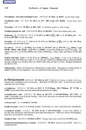
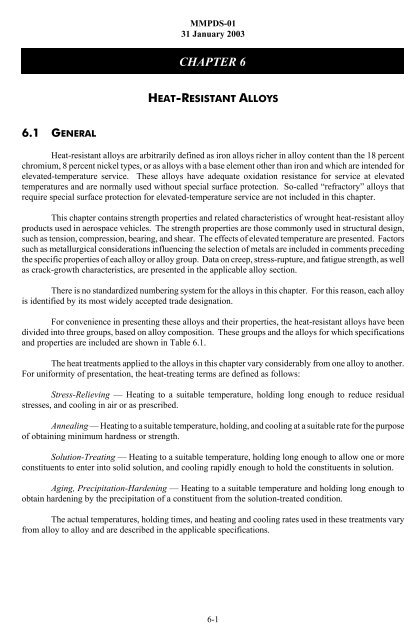
60<br />
.5 -hr exposure<br />
RT<br />
50<br />
400 F<br />
40<br />
800 F<br />
1000 F<br />
1200 F<br />
1400 F<br />
Stress, ksi<br />
30<br />
20<br />
10<br />
1800 F<br />
2000 F<br />
1600 F<br />
Ramberg - Osgood<br />
n (RT) = 10<br />
n (400 F) = 13<br />
n (800 F) = 15<br />
n (1000 F) = 18<br />
n (1200 F) = 19<br />
n (1400 F) = 15<br />
n (1600 F) = 12<br />
n (1800 F) = 7.7<br />
n (2000 F) = 3.8<br />
0<br />
0 2 4 6 8 10 12<br />
Strain, 0.001 in./in.<br />
TYPICAL<br />
Figure 6.3.1.1.6(a). Typical tensile stress-strain curves for Hastelloy X sheet at<br />
room and elevated temperatures.<br />
6-25
MMPDS-01<br />
31 January 2003<br />
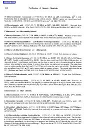
60<br />
RT<br />
RT<br />
.5 -hr exposure<br />
50<br />
700 F<br />
700 F<br />
40<br />
900 F<br />
900 F<br />
Stress, ksi<br />
30<br />
20<br />
10<br />
Ramberg - Osgood<br />
n (RT) = 6.9<br />
n (700 F) = 6.7<br />
n (900 F) = 5.6<br />
TYPICAL<br />
0<br />
0 2 4 6 8 10 12<br />
Strain, 0.001 in./in.<br />
0 5 10 15 20 25 30<br />
Compressive Tangent Modulus, 10 3 ksi<br />
Figure 6.3.1.1.6(b). Typical compressive stress-strain and compressive tangentmodulus<br />
curves for Hastelloy X bar at room and elevated temperatures.<br />
6-26
MMPDS-01<br />
31 January 2003<br />
6.3.2 INCONEL 600<br />
6.3.2.0 Comments and Properties — <strong>Inconel</strong> 600 is a corrosion- and heat-resistant nickel-base<br />
alloy used for low-stressed parts operating up to 2000EF. It is not hardenable except by cold working and<br />
is usually used in the annealed condition. <strong>Inconel</strong> 600 is available in all the usual mill forms.<br />
<strong>Inconel</strong> 600 is readily forged between 1900EF and 2250EF; “hot-cold” working between 1200EF and<br />
1600EF is harmful and should be avoided; cold working below 1200EF results in improved properties. This<br />
alloy is readily formed but should be annealed after severe forming operations. The maximum annealing<br />
temperature is 1800EF if minimum yield-strength requirements are to be met consistently. <strong>Inconel</strong> 600 is susceptible<br />
to rapid grain growth at 1800EF or higher, and exposures at these temperatures should be brief if<br />
large grain size is objectionable.<br />
<strong>Inconel</strong> 600 is somewhat difficult to machine because of its toughness and capacity for work<br />
hardening; high-speed steel or cemented-carbide tools should be used, and tools should be kept sharp. This<br />
alloy can be resistance or fusion welded or brazed (using nonsilver containing brazing alloy); large or<br />
complex fusion weldments should be stress relieved at 1600EF for 1 hour. Oxidation resistance of <strong>Inconel</strong><br />
600 is excellent up to 2000EF in sulfur-free atmospheres. This alloy is subject to attack in sulfur-containing<br />
atmospheres.<br />
Table 6.3.2.0(a). Material Specifications for <strong>Inconel</strong> 600<br />
Specification Form Condition<br />
AMS 5540<br />
ASTM B166<br />
AMS 5580<br />
ASTM B564<br />
Plate, sheet, and strip<br />
Bar and rod<br />
Tubing, seamless<br />
Forging<br />
Annealed<br />
Various<br />
Annealed<br />
Annealed<br />
Some material specifications for <strong>Inconel</strong> 600 are presented in Table 6.3.2.0(a). Room-temperature<br />
mechanical and physical properties are shown in Tables 6.3.2.0(b), (c), and (d). Figure 6.3.2.0 shows the<br />
effect of temperature on the physical properties.<br />
6.3.2.1 Annealed Condition — Elevated-temperature data for this condition are shown in<br />
Figures 6.3.2.1.1 through 6.3.2.1.4.<br />
6-27
MMPDS-01<br />
31 January 2003<br />
Table 6.3.2.0(b). Design Mechanical and Physical Properties of <strong>Inconel</strong> 600<br />
Specification .......... AMS 5540 AMS 5580 ASTM B564<br />
Form................. Sheet, strip, and plate Tubing Forging<br />
Condition ............. Annealed Cold drawn Annealed<br />
Thickness, in. .......... 0.020-2.000 ... ...<br />
Outside Diameter, in. .... ... #5.000<br />
5.001-<br />
6.625<br />
...<br />
Basis................. S S S S<br />
Mechanical Properties:<br />
F tu , ksi:<br />
L ................. ... 80 80 80<br />
LT ................ 80 ... ... ...<br />
F ty , ksi:<br />
L ................. ... 35 30 35<br />
LT ................ 35 ... ... ...<br />
F cy , ksi:<br />
L ................. ... 35 30 35<br />
LT ................ 35 ... ... ...<br />
F su , ksi .............. 51 51 51 51<br />
F bru , ksi:<br />
(e/D = 1.5).......... ... ... ... ...<br />
(e/D = 2.0).......... 152 152 152 152<br />
F bry , ksi:<br />
(e/D = 1.5).......... ... ... ... ...<br />
(e/D = 2.0).......... ... ... ... ...<br />
e, percent:<br />
L ................. ... 30 35 30<br />
LT ................ 30 ... ... ...<br />
E, 10 3 ksi ............ 30.0<br />
E c , 10 3 ksi ........... 30.0<br />
G, 10 3 ksi............ 11.0<br />
µ .................. 0.29<br />
Physical Properties:<br />
ω, lb/in. 3 ............ 0.304<br />
C, K, and α .......... See Figure 6.3.2.0<br />
6-28
MMPDS-01<br />
31 January 2003<br />
Table 6.3.2.0(c). Design Mechanical and Physical Properties of <strong>Inconel</strong> 600 Bar and Rod<br />
Specification ....... ASTM B166<br />
Form.............. Round Square, hexagon, and rectangle<br />
Condition ..........<br />
Cold-worked<br />
Thickness, in. ....... #0.499 0.500-1.000 1.001-2.500 #0.250 0.251-0.499<br />
Basis.............. S S S S S<br />
Mechanical Properties a :<br />
F tu , ksi:<br />
L .............. 120 110 105 100 95<br />
LT ............. ... ... ... ... ...<br />
F ty , ksi:<br />
L .............. 90 85 80 80 70<br />
LT ............. ... ... ... ... ...<br />
F cy , ksi:<br />
L .............. ... ... ... ... ...<br />
LT ............. ... ... ... ... ...<br />
F su , ksi ........... ... ... ... ... ...<br />
F bru , ksi:<br />
(e/D = 1.5)....... ... ... ... ... ...<br />
(e/D = 2.0)....... ... ... ... ... ...<br />
F bry , ksi:<br />
(e/D = 1.5)....... ... ... ... ... ...<br />
(e/D = 2.0)....... ... ... ... ... ...<br />
e, percent:<br />
L .............. 7 b 10 12 5 b 7<br />
E, 10 3 ksi ......... 30.0<br />
E c , 10 3 ksi ........ 30.0<br />
G, 10 3 ksi......... 11.0<br />
µ ............... 0.29<br />
Physical Properties:<br />
ω, lb/in. 3 ......... 0.304<br />
C, K, and α ....... See Figure 6.3.2.0<br />
a Mechanical property requirements apply only when specified by purchaser.<br />
b Not applicable to thickness
MMPDS-01<br />
31 January 2003<br />
Table 6.3.2.0(d). Design Mechanical and Physical Properties of <strong>Inconel</strong> 600 Bar and Rod<br />
Specification ............ ASTM B166<br />
Form...................<br />
Round<br />
Square,<br />
hexagon, and Bar and rod<br />
rectangle<br />
Condition ............... Hot-worked Annealed<br />
Thickness, in. ............ 0.250-0.500 0.501-3.000 >3.000 All All<br />
Basis................... S S S S S<br />
Mechanical Properties a :<br />
F tu , ksi:<br />
L ................... 95 90 85 85 80<br />
LT .................. ... ... ... ... ...<br />
F ty , ksi:<br />
L ................... 45 40 35 35 35<br />
LT .................. ... ... ... ... ...<br />
F cy , ksi:<br />
L ................... ... ... ... ... 35<br />
LT .................. ... ... ... ... ...<br />
F su , ksi ................ ... ... ... ... 51<br />
F bru , ksi:<br />
(e/D = 1.5)............ ... ... ... ... ...<br />
(e/D = 2.0)............ ... ... ... ... 152<br />
F bry , ksi:<br />
(e/D = 1.5)............ ... ... ... ... ...<br />
(e/D = 2.0)............ ... ... ... ... ...<br />
e, percent:<br />
L ................... 20 25 30 ... 30 b<br />
E, 10 3 ksi .............. 30.0<br />
E c , 10 3 ksi ............. 30.0<br />
G, 10 3 ksi.............. 11.0<br />
µ .................... 0.29<br />
Physical Properties:<br />
ω, lb/in. 3 .............. 0.304<br />
C, K, and α ............ See Figure 6.3.2.0<br />
a Mechanical property requirements apply only when specified by purchaser.<br />
b Not applicable to thickness >0.094 inch.<br />
6-30
MMPDS-01<br />
31 January 2003<br />
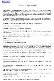
Figure 6.3.2.0. Effect of temperature on the physical properties of <strong>Inconel</strong> 600.<br />
6-31
MMPDS-01<br />
31 January 2003<br />
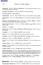
Figure 6.3.2.1.1. Effect of temperature on the tensile ultimate strength (F tu ) and the<br />
tensile yield strength (F ty ) of <strong>Inconel</strong> 600.<br />
Figure 6.3.2.1.2. Effect of temperature on the compressive yield strength (F cy ) and the<br />
shear ultimate strength (F su ) of <strong>Inconel</strong> 600.<br />
6-32
MMPDS-01<br />
31 January 2003<br />
Next page<br />
Figure 6.3.2.1.3. Effect of temperature on the bearing ultimate strength (F bru ) of<br />
<strong>Inconel</strong> 600.<br />
Figure 6.3.2.1.4. Effect of temperature on the tensile and compressive moduli (E and E c )<br />
of <strong>Inconel</strong> 600.<br />
6-33