Technical Data - Link-Belt Construction Equipment
Technical Data - Link-Belt Construction Equipment
Technical Data - Link-Belt Construction Equipment

Create successful ePaper yourself
Turn your PDF publications into a flip-book with our unique Google optimized e-Paper software.
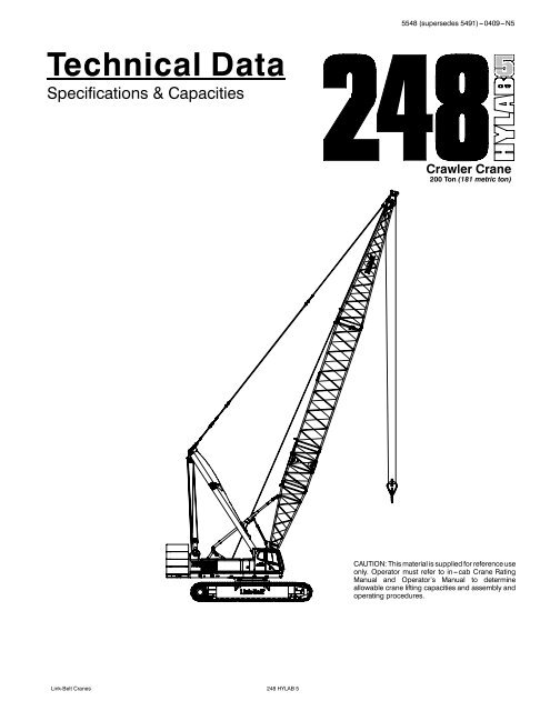
<strong>Technical</strong> <strong>Data</strong><br />
Specifications & Capacities<br />
<strong>Link</strong>-<strong>Belt</strong> Cranes<br />
248 HYLAB 5<br />
5548 (supersedes 5491)---0409---N5<br />
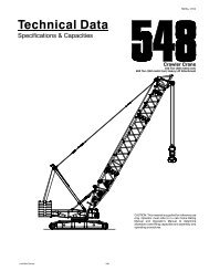
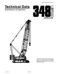
Crawler Crane<br />
200 Ton (181 metric ton)<br />
CAUTION: This material is supplied for reference use<br />
only. Operator must refer to in---cab Crane Rating<br />
Manual and Operator’s Manual to determine<br />
allowable crane lifting capacities and assembly and<br />
operating procedures.<br />
1
5548 (supersedes 5491)---0409---N5<br />
248 HYLAB 5 <strong>Link</strong>-<strong>Belt</strong> Cranes
Table Of Contents<br />
<strong>Link</strong>-<strong>Belt</strong> Cranes<br />
248 HYLAB 5<br />
5548 (supersedes 5491)---0409---N5<br />
Upper Structure ............................................................................ 1<br />
Frame .................................................................................... 1<br />
Engine ................................................................................... 1<br />
Hydraulic System .......................................................................... 1<br />
Load Hoist Drums ......................................................................... 1<br />
Optional Front---Mounted Third Hoist Drum ................................................... 1<br />
Boom Hoist Drum .......................................................................... 2<br />
Swing System ............................................................................. 2<br />
Counterweight ............................................................................ 2<br />
Operator’s Cab ............................................................................ 2<br />
Rated Capacity Limiter System .............................................................. 2<br />
Boom Hoist System ........................................................................ 2<br />
Machinery Cab ............................................................................ 2<br />
Catwalks ................................................................................. 2<br />
Lower Structure ............................................................................ 3<br />
Carbody .................................................................................. 3<br />
Side Frames .............................................................................. 3<br />
Travel and Steering ........................................................................ 3<br />
Jack System .............................................................................. 3<br />
Attachment and Options .................................................................... 3<br />
Conventional Tubular Boom ................................................................. 3<br />
Tubular Jib ................................................................................ 4<br />
Luffing Boom .............................................................................. 4<br />
Auxiliary Tip Extension ...................................................................... 4<br />
Luffing Jib ................................................................................ 4<br />
Fixed Jib .................................................................................. 4<br />
Dimensions ................................................................................ 5<br />
Base Crane ............................................................................... 7<br />
Side Frames .............................................................................. 7<br />
Upper Counterweights ..................................................................... 8<br />
Lower Counterweights ..................................................................... 8<br />
Boom/Luffing Boom ........................................................................ 9<br />
Jib ....................................................................................... 11<br />
Luffing Jib ................................................................................ 12<br />
Hook Blocks .............................................................................. 13<br />
Hook Balls ................................................................................ 13<br />
Working Weights ........................................................................... 14<br />
Transport Weights .......................................................................... 14<br />
Transport Drawings ........................................................................ 15<br />
Load Hoist Performance .................................................................... 18<br />
Working Areas ............................................................................. 19<br />
Attachments ............................................................................... 20<br />
Main Boom Make--up ...................................................................... 21<br />
Main Boom Working Range Diagram ........................................................<br />
22
5548 (supersedes 5491)---0409---N5<br />
Main Boom Load Charts .................................................................... 23<br />
Jib Attachment Make--up ................................................................... 25<br />
Jib Attachment Working Range Diagram ..................................................... 26<br />
Jib Attachment Load Charts ................................................................. 27<br />
Luffing Attachment Make--up ............................................................... 31<br />
Luffing Boom Make---up .................................................................... 31<br />
Luffing Jib Make---up ....................................................................... 31<br />
Luffing Attachment Working Range Diagrams ................................................ 32<br />
Luffing Attachment Load Charts ............................................................. 36<br />
Luffing Attachment Transport ...............................................................<br />
47<br />
248 HYLAB 5 <strong>Link</strong>-<strong>Belt</strong> Cranes
5548 (supersedes 5491)---0409---N5<br />
Upper Structure<br />
Frame<br />
All welded and precision machined<br />
surfaces.<br />
Turntable Bearing<br />
S Outer race bolted to upper frame; inner<br />
race with internal swing gears bolted to<br />
lower frame.<br />
Engine<br />
Engine<br />
Full pressure lubrication, oil filter, air<br />
cleaner, hour meter, throttle, and electric<br />
control shutdown.<br />
Isuzu AH--6HK1X<br />
Number of cylinders 6<br />
Bore and stroke<br />
<strong>Link</strong>-<strong>Belt</strong> Cranes<br />
4.53 in x 4.92 in<br />
(115 x 125mm)<br />
Piston displacement 475 in 3 (7.86L)<br />
Engine rpm at full<br />
load speed<br />
2,000 rpm<br />
Hi --- idle rpm 2,050 rpm<br />
Gross engine hp 284 hp (212kw)<br />
Peak torque<br />
Electrical system 24 volt<br />
830 ft lb (1 125joule) @<br />
1,500 rpm<br />
Fuel tank capacity 77 gal (291.5L)<br />
Batteries 2 --- 12 volt<br />
Approximate fuel<br />
consumption<br />
gal/hr (L/hr)<br />
100% hp 14.4 (54.51)<br />
75% hp 11.7 (44.29)<br />
50% hp 8.4 (31.80)<br />
25% hp 4.2 (15.89)<br />
Fuel Tank<br />
Equipped with fuel sight level gauges,<br />
flame arrester, and self---closing cap with<br />
locking eye for padlock.<br />
Hydraulic System<br />
Hydraulic Pumps<br />
The pump arrangement is designed to<br />
provide hydraulically powered functions<br />
allowing positive, precise control with independent<br />
or simultaneous operation of<br />
all crane functions.<br />
S Two variable displacement pumps<br />
operating at 4,451 psi (320kg/cm 2 )and<br />
83 gal/min (314.2L/min) powers load<br />
hoist drums, boom hoist drum, optional<br />
thirddrum,andtravel.<br />
S Two fixed displacement gear type pumps<br />
operating at 3,342 psi (235kg/cm 2 )and<br />
21 gal/min (79.5L/min)powerstheswing<br />
motor, lower jacks, and counterweight<br />
removal.<br />
S One fixed displacement gear type pump<br />
operating at 1,991 psi (140kg/cm 2 ) and<br />
8.4 gal/min (31.8L/min) powers the fan<br />
for the oil cooler.<br />
S One fixed displacement gear type<br />
pump operating at 1,138 psi<br />
(80kg/cm2 ) and 10.8 gal/min<br />
(40.6L/min) powers the remote control<br />
valves.<br />
Remote Oil Cooler<br />
Oil cooler, located behind the operator’s<br />
cab, has a hydraulically driven, thermostatically<br />
controlled fan to control oil temperature.<br />
Pump Control “Fine Inching” Mode<br />
Special pump setting, selectable from the<br />
operator’s cab, that allows very slow<br />
movements of load hoist drums, boom<br />
hoist drum, and travel for precision work.<br />
Hydraulic Reservoir<br />
42 gal (159.0L), equipped with sight level<br />
gauge. Diffusers built in for deaeriation.<br />
Filtration<br />
Ten micron, full flow, line filter in the control<br />
circuit. All oil is filtered prior to entering the<br />
reservoir.<br />
Counterbalance Valves<br />
All hoist motors are equipped with counterbalance<br />
valves to provide positive load<br />
lowering and prevent accidental load<br />
drop if the hydraulic pressure is suddenly<br />
lost.<br />
248 HYLAB 5<br />
Load Hoist Drums<br />
1<br />
Each drum contains a pilot controlled, bi-directional,<br />
axial piston motor and a planetary<br />
gear reduction unit to provide positive<br />
control under all load conditions.<br />
S Power up/down and free---fall operation<br />
modes<br />
S Automatic brake mode (spring applied,<br />
hydraulically released, band type<br />
brake)<br />
S Grooved lagging<br />
S Drum pawl controlled manually<br />
S Electronic drum rotation indicators<br />
S Mounted on anti---friction bearings<br />
S 19.00 in (48.26cm) root diameter<br />
S 33.86 in (86.00cm) flange diameter<br />
S 22.52 in (57.20cm) width<br />
The free---fall operation mode is designed<br />
to prevent load lowering even if the free-fall<br />
switch is accidentally activated.<br />
The automatic brake mode meets all<br />
OSHA requirements for personnel handling.<br />
Drum Clutches<br />
Hydraulic two shoe clutch design that<br />
uses a 30 in (762mm) diameter x 6.5 in<br />
(165mm) wide shoe that expands internally<br />
to provide load control. Swept area<br />
is 314.16 in2 (2 026.83cm2 ).<br />
Optional Front---Mounted<br />
Third Hoist Drum<br />
Mounts in the boom base section and is<br />
used in conjunction with a fleeting sheave<br />
and 3---sheave idler assembly to run the<br />
wire rope over the boom top section.<br />
S Power up/down for luffer applications<br />
where a second load line is needed<br />
S 18.70 in (475mm) root diameter<br />
S 33.66 in (855mm) flange diameter<br />
S 32.00 in (813mm) width<br />
S Mounted on anti---friction bearings
2 5548 (supersedes 5491)---0409---N5<br />
Boom Hoist Drum<br />
Contains a pilot controlled, bi---directional,<br />
axial piston motor and a planetary gear reduction<br />
unit to provide positive control under<br />
all load conditions.<br />
S Spring applied, hydraulically released,<br />
disc type brake controlled automatically<br />
S Grooved lagging<br />
S Drum pawl controlled automatically<br />
S Mounted on anti---friction bearings<br />
S 14.99 in (38.07cm) root diameter<br />
S 30.71 in (78.00cm) flange diameter<br />
S 11.55 in (29.34cm) width<br />
Swing System<br />
Pilot controlled bi---directional axial piston<br />
motors and planetary gear reduction units<br />
to provide positive control under all load<br />
conditions.<br />
S Spring applied, hydraulically released,<br />
360˚ multi --- plate brake<br />
S Free swing mode when lever is in neutral<br />
position<br />
S Four position positive house lock<br />
S Two---speed swing<br />
S Audio/Visual swing alarm<br />
S Maximum swing speed is 1.92 rpm<br />
Counterweight<br />
Consists of a five---piece design that can<br />
be easily lowered to the ground using the<br />
hydraulic counterweight removal cylinders.<br />
S “A” upper counterweight consists of<br />
one, 14,000 lb (6 350kg) base slab and<br />
two, 13,000 lb (5 897kg) wing weights.<br />
S “B” upper counterweight consists of<br />
two, 13,000 lb (5 897kg) wing weights.<br />
S “C” upper counterweight consists of<br />
two, 13,000 lb (5 897kg) wing weights.<br />
S Optional “D” upper counterweight consists<br />
of two, 13,000 lb (5 897kg) wing<br />
weights.<br />
S Two side frame counterweights ---<br />
24,000 lb (10 886kg) each for 44 in<br />
(1.12m) track shoes, 21,500 lb (9<br />
752kg) eachfor50in(1.27m) track<br />
shoes.<br />
Total combined counterweight, “ABCD”<br />
plus side frames counterweights, is<br />
166,000 lb (75 296kg) for 44 in (1.12m)<br />
track shoes, 161,000 lb (73 030kg) for<br />
50 in (1.27m) trackshoes.<br />
Operator’s Cab<br />
Fully enclosed modular steel compartment<br />
is independently mounted and<br />
padded to protect against vibration and<br />
noise.<br />
S All tinted/tempered safety glass<br />
S Folding hinge entry door andsliding<br />
front glass window<br />
S 19,000 BTU hot water heater<br />
S 18,600 BTU air conditioner<br />
S Door and window locks<br />
S Circulating fan<br />
S Sun visor<br />
S Cloth seat<br />
S Defroster<br />
S Windshield wipers and washer<br />
S Dry chemical fire extinguisher<br />
S Engine instrumentation panel (voltmeter,<br />
engine oil pressure, engine water temperature,<br />
fuel level, hydraulic oil temperature,<br />
hour meter, and service monitor<br />
system)<br />
S Electronic drum rotation indicators for<br />
front and rear hoist drums<br />
S Six way adjustable seat<br />
S Hand and foot throttle<br />
S Fully adjustable single axis controls<br />
S Swing lever with swing brake and horn<br />
located on handle<br />
S Bubbletypelevel<br />
S Ergonomic gauge layout<br />
S Controls shut off lever<br />
S Right hand control stand is adjustable<br />
by electric motor for operator comfort.<br />
Rated Capacity Limiter<br />
System<br />
The rated capacity limiter system is a boom<br />
hoist load cell system. This system provides<br />
the operator with useful geometrical<br />
data, to include:<br />
S Main Boom Length<br />
S Main Boom Angle<br />
S Jib Length<br />
S Jib Angle<br />
S Operating Mode<br />
S Load Radius<br />
S Boom Tip Height<br />
S Audible Alarm<br />
S Pre---Warning Light<br />
S Overload Light<br />
S Load On Hook<br />
S Function kick---outs including over load<br />
S Operator settable stops (ramped stops)<br />
S Anti---Two Block Indicator<br />
S Boom hoist dead end load cell (no<br />
lineriders)<br />
Boom Hoist System<br />
Designed to lift off maximum boom or<br />
maximum boom plus jib and maximum<br />
luffing attachment unassisted. Operates<br />
up to a maximum boom angle of 80_.<br />
Boom hoist limit system limits maximum<br />
boom angle operation.<br />
S Pin --- on bail frame<br />
S 16---part reeving with 7/8 in (22mm)<br />
wire rope<br />
S Bridle assembly<br />
S 30 ft (9.14m) live mast<br />
S Tubular boom backstops (telescopic<br />
type)<br />
S Sheaves contain sealed anti---friction<br />
bearings<br />
S Boom speed from 10˚--- 70˚ is 90 seconds<br />
with no load. Speed was determined<br />
using 100 ft (30.48m) of tube<br />
boom.<br />
Machinery Cab<br />
Hinged doors (one on right side, two on<br />
left side) for machinery access. Equipped<br />
with rooftop access ladder and skid resistant<br />
finish on roof.<br />
Catwalks<br />
Standard on right and left sides. Catwalks<br />
are removable for reduced travel width.<br />
248 HYLAB 5 <strong>Link</strong>-<strong>Belt</strong> Cranes
5548 (supersedes 5491)---0409---N5<br />
Lower Structure<br />
Carbody<br />
Lower Frame<br />
All welded high strength steel [100,000<br />
psi (689.48MPa) yield] box construction<br />
frame with precision machined surfaces<br />
for turntable bearing and rotating joint.<br />
S 20 ft 4 in (6.20m) overall width<br />
S 11 ft 9.75 in (3.60m) overall length<br />
Side Frames<br />
Side Frames<br />
All welded, precision machined and removable.<br />
Carbody cross axles positioned<br />
by dowels and held in place with adjustable<br />
wedge packs.<br />
S 18 ft 10 in (5.74m) gauge<br />
S 28 ft 6 in (8.69m) overall length<br />
S 44 in (1.12m) wide track shoes<br />
S Sealed (oil filled) drive planetaries<br />
S Compact travel drives<br />
S Slide rails on top of each side frame<br />
S Optional --- 50 in (1.27m) widetrack<br />
shoes<br />
<strong>Link</strong>-<strong>Belt</strong> Cranes<br />
Track Rollers<br />
S Eleven sealed (oil filled) track rollers per<br />
side frame<br />
S Heat treated, mounted on anti---friction<br />
bearings<br />
Tracks<br />
Heat treated, self---cleaning, multiple<br />
hinged track shoes joined by one---piece<br />
full floating pins; 50 shoes per side frame<br />
Take Up Idlers<br />
Cast steel, heat treated, self---cleaning,<br />
mounted on sealed tapered roller bearings.<br />
S Track Tension Adjustment --- Idler<br />
wheel adjusted by means of hydraulic<br />
cylinder and hand pump. Idler wheel<br />
shaft held in position with shims after<br />
adjustment is made.<br />
Travel and Steering<br />
Travel and Steering<br />
Each side frame contains a pilot controlled,<br />
bi---directional, axial piston motor<br />
and a planetary gear reduction unit to provide<br />
positive control under all load conditions.<br />
Attachment and Options<br />
Conventional Tubular Boom<br />
50--280 ft (15.24---83.34m)<br />
Basic Boom<br />
50 ft (15.24m) two---piece design that<br />
utilizes a 20 ft (6.10m) base section and<br />
a30ft(9.14m) open throat top section<br />
with in---line connecting pins on 80 in<br />
(2.03m) wide and 68 in (1.73m) deep<br />
centers.<br />
S Boom foot on 55 in (1.40m) centers<br />
S 4in(10.16cm) diameter chords<br />
S Lugs on base section to attach carrying<br />
links<br />
S Skywalk platform<br />
S Deflectorrollerontopsection<br />
S Permanent skid pads mounted on top<br />
section to protect head machinery<br />
S Appropriate length bar pendants<br />
stored on top section.<br />
S Six, 21 in, (0.53m) root diameter steel<br />
sheaves mounted on sealed anti---friction<br />
bearings<br />
S Tip extension and jib connecting lugs<br />
on top section<br />
S Mechanical boom angle indicator<br />
Tube Boom Extensions<br />
The following table provides the lengths<br />
available and the suggested quantity to obtain<br />
maximum boom in 10 ft (3.05m) increments.<br />
Midpoint pendant connections are<br />
required at 110 ft (33.5m) for boom lengths<br />
of 250---280 ft (76.20---85.34m).<br />
S Polyamide wear blocks on top of each<br />
extension<br />
S Appropriate length bar pendants<br />
stored on extension<br />
248 HYLAB 5<br />
3<br />
S 2---speed travel.<br />
S Individual control provides smooth,<br />
precise maneuverability including full<br />
counter---rotation.<br />
S Spring applied, hydraulically released<br />
disc type brake controlled automatically<br />
S Maximum travel speed is 0.85 mph<br />
(1.37km/h).<br />
S Designed to 30% gradeability<br />
Jack System<br />
System contains four hydraulic cylinders<br />
individually pinned on the carbody.<br />
S Standard; four ground controlled, power<br />
hydraulic jacks, pinned to the lower<br />
carbody frame, used to raise the crane<br />
to facilitate removal and installation of<br />
the crawler side frames.<br />
S Individual controls are mounted on carbody.<br />
S Minimum height of carbody when resting<br />
on pontoons is 21.50 in (54.61cm).<br />
S Maximum height of carbody when resting<br />
on pontoons is 37.50 in (0.95m).<br />
Tube Boom<br />
Extensions Quantity For Max<br />
Boom<br />
ft m<br />
10 3.05 1*<br />
20 6.10 1<br />
30 9.14 2<br />
40 12.19 1<br />
50 15.24 2<br />
* Assumes one 10 ft (3.05m) extension<br />
is the self---assembly section.<br />
S Maximum tip height of 285 ft (86.87m)<br />
S Boom connecting pins storage on each<br />
extension
4 5548 (supersedes 5491)---0409---N5<br />
Tubular Jib<br />
30--100 ft (9.14---30.48m)<br />
Basic Tube Jib<br />
30 ft (9.14m) two---piece design that utilizes<br />
a 15 ft (4.57m) base section and a<br />
15 ft (4.57m) top section with in---line<br />
connecting pins on 32 in (0.81m) wide<br />
and 24 in (0.61m) deep centers.<br />
S 2.25 in (57.15mm) diameter tubular<br />
chords<br />
S One 21 in (0.53m) root diameter steel<br />
sheave mounted on sealed anti---friction<br />
bearings<br />
S 10 ft (3.05m) and 20 ft (6.10) jib extensions<br />
are available to provide jib<br />
lengths of 30---100 ft (9.14 ---30.48m) in<br />
10 ft (3.05m) increments<br />
S Jib offset angles at 5˚, 15˚, and25˚<br />
S The maximum tip height of tube boom<br />
+ jib [240 ft + 100 ft (73.15 + 30.5m)]is<br />
345 ft (105m).<br />
S Basictubejibcanbeusedasfixedjib<br />
on luffing jib<br />
Auxiliary Tip Extension<br />
5ft(1.5m)<br />
Designed to use in place of jib to provide<br />
clearance between working hoist lines.<br />
The extension is equipped with two 21 in<br />
(0.53m) root diameter nylon sheaves<br />
mounted on sealed anti---friction bearings.<br />
Maximum capacity is 20 Tons<br />
(18.14mt).<br />
Luffing Boom<br />
80--190 ft (24.38---57.91m)<br />
S Common base and extensions as open<br />
throat boom (“FE” boom only).<br />
S 10 ft (3.05m) luffing extension required<br />
for bail anchor<br />
S Working angles of 90˚, 85˚, 80˚, 75˚,<br />
70˚, and65˚<br />
S Working lengths of 80 ft (24.38m) to<br />
190 ft (57.91m)<br />
Luffing Boom Extensions<br />
The following table provides the lengths<br />
available and the suggested quantity to<br />
obtain the maximum luffing boom in 10 ft<br />
(3.05m) increments. Midpoint pendants<br />
are not required.<br />
Luffing Boom<br />
Extensions Quantity For Max<br />
Luffing Boom<br />
ft m<br />
10* 3.05 1<br />
20 6.10 1<br />
30 9.14 1<br />
40 12.19 1<br />
50 15.24 2<br />
*10ft(3.05m) extension is the self---assembly<br />
section. Required for luffer operation.<br />
Note: “FE” type boom must be used.<br />
S Rear hoist drum becomes luffing jib<br />
hoist<br />
S Optional third drum provides second<br />
working hoist line, if required.<br />
S Designed for self---assembly<br />
S Luffing jib hoist bridle and bail can remain<br />
reeved for crane transport<br />
S Job site mobility with attachment<br />
S Rolled out or rolled under erection<br />
methods<br />
S Compact transport module<br />
Luffing Jib<br />
80--160 ft (24.38---48.77m)<br />
Basic Luffing Jib<br />
80 ft (24.38m) five---piece design utilizes a<br />
4ft(1.12m) luffing boom top section, 10 ft<br />
(3.05m) luffing jib base section, 20 ft<br />
(6.10m) jib extension, 30 ft (6.10m) extension,<br />
and 20 ft (6.10m) top section with<br />
in---line connecting pins. Jib extensions<br />
are 60 in (1.52m) wide and 50 in (1.27m)<br />
deep at the centers.<br />
S 42.5 Tons (38.56mt) maximum capacity<br />
S Working lengths of 80 ft (24.38m) to<br />
160 ft (48.77m)<br />
S Top section includes mounting lugs for<br />
all attachment options<br />
S Five 21 in (0.53m) diameter luffing jib<br />
steel head sheaves<br />
S Pin --- on nose wheel<br />
S Ten --- part luffing jib hoist<br />
S 1in(25.40mm) diameter type “N” pendants<br />
Luffing Jib Extensions<br />
The following table provides the lengths<br />
available and the suggested quantity to<br />
obtain the maximum luffing jib in 10 ft<br />
(3.05m) increments. Midpoint pendants<br />
are not required.<br />
Luffing Jib<br />
Extensions Quantity For Max<br />
Luffing Jib<br />
ft m<br />
10 3.05 1<br />
20 6.10 1<br />
30 9.14 1<br />
40 12.19 1<br />
Notes:<br />
These extensions, combined with extensions<br />
included in basic luffing jib, make<br />
up all jib lengths to 160 ft (48.77m).<br />
S 50 ft (15.24m) of extensions are<br />
included with basic jib.<br />
S Deflector roller on top of each extension<br />
S Appropriate length pendants<br />
S Maximum luffing jib tip height of 350.8 ft<br />
(107m)<br />
Fixed Jib<br />
30 ft (9.14m)<br />
30 ft (9.14m) two---piece design commonwithbasictubejibthatutilizesa15<br />
ft (4.57m) base section and a 15 ft<br />
(4.57m) top section with in---line connecting<br />
pins on 32 in (0.81m) wide and<br />
24 in (0.61m) deep centers.<br />
S 2.25 in (57.15mm) diameter tubular<br />
chords<br />
S One 21 in (0.53m) root diameter steel<br />
sheave mounted on sealed anti---friction<br />
bearings<br />
S Fixed jib offset angle is 5˚<br />
S Maximum luffing jib + fixed jib tip height<br />
of 379.4 ft (115.6m)<br />
248 HYLAB 5 <strong>Link</strong>-<strong>Belt</strong> Cranes
5548 (supersedes 5491)---0409---N5<br />
Dimensions<br />
General Dimensions English Metric<br />
Basic Boom 50 ft 15.24m<br />
Minimum Load Radius 12 ft 3.66m<br />
Maximum Boom Angle 80˚ 80˚<br />
Track Shoe Width 44 in* 1.12m<br />
**<br />
25’ 8”<br />
(7.83m)<br />
<strong>Link</strong>-<strong>Belt</strong> Cranes<br />
13’ 3”<br />
(4.04m)<br />
5’ 5”<br />
(1.65m)<br />
Maximum height of<br />
live mast from ground<br />
is 39’ 7” (12.06m)<br />
22’ 0.75” (6.71m)<br />
28’ 6” (8.69m)<br />
18’ 2.25” (5.54m)<br />
248 HYLAB 5<br />
7’ 6.75”<br />
(2.31m)<br />
Note: * Optional --- 50 in (1.27m) trackshoewidth<br />
** @ Maximum boom angle (80˚) with maximum boom [280 ft (85.34m)], maximum rotation radius occurs.<br />
5
6 5548 (supersedes 5491)---0409---N5<br />
Tailswing Radius<br />
19’ 10” (6.05m)<br />
15’ 2”<br />
(4.62m)<br />
52.75”<br />
(1.34m)<br />
44”*<br />
(1.12m)<br />
* Optional --- 50” (1.27m)<br />
** With 50” (1.27m) track shoes, dimension is 23’ 0” (7.01m).<br />
23’ 7.50”<br />
(7.20m)<br />
22’ 6”**<br />
(6.86m)<br />
14’ 0.75”<br />
(4.28m)<br />
11’ 4.75”<br />
(3.35m)<br />
14.75”<br />
(37.47cm)<br />
22”<br />
(55.88cm)<br />
248 HYLAB 5 <strong>Link</strong>-<strong>Belt</strong> Cranes
5548 (supersedes 5491)---0409---N5<br />
Base Crane<br />
Base Crane �<br />
Length 1 20 ft 4 in (6.20m)<br />
Length 2 52 ft (15.85m)<br />
Length 3 8 ft 4 in (2.54m)<br />
Width 9 ft 1.50 in (2.78m)<br />
Height 1 11 ft 3 in (3.43m)<br />
Height 2 37.50 in (0.95m)<br />
Height 3 44.0 in (1.12m)<br />
Weight 83,332 lb (37 799kg)<br />
H1<br />
H3<br />
L3<br />
Side Frames<br />
With 44 in (1.12m) TrackShoes �<br />
Length 28 ft 6 in (8.69m)<br />
Width 44 in (1.12m)<br />
Height 52.75 in (1.34m)<br />
Weight 36,410 lb (16 515kg)<br />
With 50 in (1.27m) TrackShoes �<br />
Length 28 ft 6 in (8.69m)<br />
Width 50 in (1.27m)<br />
Height 52.75 in (1.34m)<br />
Weight 37,610 lb (17 060kg)<br />
Number inside black circle “�” = # of components<br />
<strong>Link</strong>-<strong>Belt</strong> Cranes<br />
L1<br />
W<br />
H<br />
H2*<br />
* Maximum height<br />
on pontoons<br />
H3A0194 2418 -LB<br />
! CAUTION<br />
! DIRECTION TO TR BEAD E PAR M EM ALLEL OFARROW<br />
B ERTO<br />
WHILEUNLATCHING<br />
STAND PERSONALINJURY<br />
DROPPING COULD CAUTION<br />
RESULTIN FLOAT<br />
CLEAR OF PAD<br />
DO NOTBRIDGE<br />
L2<br />
248 HYLAB 5<br />
W<br />
L<br />
PART NUMBER CONSTRUCTION LGN2P0017 DATE<br />
HIGH DO NOT STR ENGTH EQUIPMENT STEEL<br />
ON THIS MATERIAL<br />
N2P0014 DRILLOR WELD<br />
7
8 5548 (supersedes 5491)---0409---N5<br />
Upper Counterweights<br />
“A” Slab Counterweight �<br />
Length 5ft9.50in (1.77m)<br />
Width 15 ft 2 in (4.62m)<br />
Height 32.25 in (0.82m)<br />
Weight 14,000 lb (6 350kg)<br />
“A”, “B”, “C”, and “D” (2 Each)<br />
Wing Counterweights �<br />
Length 1 61 in (1.55m)<br />
Length 2 46.50 in (1.18m)<br />
Width 50.75 in (1.29m)<br />
Height 20.25 in (51.44cm)<br />
Weight 13,000 lb (5 897kg)<br />
Lower Counterweights<br />
Side Frame Counterweights<br />
With 44 in (1.12m) Track<br />
Shoes �<br />
Length 16 ft 8 in (5.08m)<br />
Width 17.50 in (44.45cm)<br />
Height 33.75 in (0.86m)<br />
Weight 24,000 lb (10 886kg)<br />
Side Frame Counterweights<br />
With 50 in (1.27m) Track<br />
Shoes �<br />
Length 16 ft (4.88m)<br />
Width 17.40 in (44.20cm)<br />
Height 31.10 in (0.79m)<br />
Weight 21,500 lb (9 752kg)<br />
Number inside black circle “�” = # of components<br />
H<br />
L<br />
H<br />
W<br />
H<br />
L1<br />
L2<br />
L<br />
W<br />
248 HYLAB 5 <strong>Link</strong>-<strong>Belt</strong> Cranes<br />
L2<br />
L1<br />
W
5548 (supersedes 5491)---0409---N5<br />
Boom/Luffing Boom<br />
80 in (2.03m) x68in(1.73m)<br />
Boom/Luffing Boom Extensions*<br />
Weights Include Pendants and Hardware<br />
10 ft (3.05m) Extension<br />
Weight: 1,151 lb (522kg)<br />
20 ft (6.10m) Extension<br />
Weight: 1,862 lb (845kg)<br />
30 ft (9.14m) Extension<br />
Weight: 2,590 lb (1 175kg)<br />
40 ft (12.19m) Extension<br />
Weight: 3,292 lb (1 493kg)<br />
50 ft (15.24m) Extension<br />
Weight: 4,149 lb (1 882kg)<br />
<strong>Link</strong>-<strong>Belt</strong> Cranes<br />
80.5”<br />
(2.04m)<br />
80.5”<br />
(2.04m)<br />
80.5”<br />
(2.04m)<br />
80.5”<br />
(2.04m)<br />
80.5”<br />
(2.04m)<br />
86.5” (2.20m)<br />
86.5” (2.20m)<br />
86.5” (2.20m)<br />
86.5” (2.20m)<br />
86.5” (2.20m)<br />
* Standard, conventional boom uses bar pendants as shown. Bar pendants must be<br />
removed and replaced with wire rope pendants for luffing boom make---up.<br />
248 HYLAB 5<br />
20’ 4.75”<br />
(6.22m)<br />
10’ 4.75”<br />
(3.17m)<br />
30’ 4.75”<br />
(9.26m)<br />
40’ 4.75”<br />
(12.31m)<br />
50’ 4.75”<br />
(15.36m)<br />
9
10 5548 (supersedes 5491)---0409---N5<br />
30 ft (9.14m) Boom Top<br />
Section �<br />
Length 32 ft 10 in (10.01m)<br />
Width 86.50 in (2.20m)<br />
Deep 68 in (1.73m)<br />
Height 80.50 in (2.04m)<br />
Weight 4,488 lb (2 036kg)<br />
20 ft (6.10m) Boom Base<br />
Section �<br />
Length 20 ft 8 in (6.30m)<br />
Width 86.38 in (2.19m)<br />
Deep 68 in (1.73m)<br />
Height 76.40 in (1.94m)<br />
Weight Without 3rd Drum<br />
4,479 lb (2 032kg)<br />
Weight With 3rd Drum & Wire Rope*<br />
9,035 lb (4 098kg)<br />
10 ft (3.05m) Self<br />
Assembly Section* �<br />
Length 10 ft 4 in (3.15m)<br />
Width 86.50 in (2.20m)<br />
Deep 68.00 in (1.73m)<br />
Height 80.50 in (2.04m)<br />
Weight 2,422 lb (1 099kg)<br />
Number inside black circle “�” = # of components<br />
* --- Optional equipment<br />
W<br />
D<br />
W<br />
D<br />
L<br />
L<br />
L<br />
248 HYLAB 5 <strong>Link</strong>-<strong>Belt</strong> Cranes<br />
H<br />
W<br />
D<br />
H<br />
H
5548 (supersedes 5491)---0409---N5<br />
5ft(1.52m) Auxiliary Tip<br />
Extension* �<br />
Length 70.35 in (1.79m)<br />
Width 24.50 in (0.62m)<br />
Height 42.91 in (1.09m)<br />
Weight 671 lb (304kg)<br />
Jib<br />
15 ft (4.57m) Jib<br />
Top Section* �<br />
Length 16 ft 1.50 in (4.91m)<br />
Width 34.50 in (0.88m)<br />
Height 26.75 in (0.68m)<br />
Weight † 607 lb (275kg)<br />
† Weight includes sheaves and hardware.<br />
15 ft (4.57m) Jib<br />
Base Section* �<br />
Length 15 ft 3.50 in (4.66m)<br />
Width 34.50 in (0.88m)<br />
Height 1 26.75 in (0.68m)<br />
Height 2 54.50 in (1.38m)<br />
Weight † 1,602 lb (727kg)<br />
† Weight includes pins, basic frontstay & backstay<br />
pendants, and hardware.<br />
10 ft (3.05m) Jib<br />
Extension* �<br />
Length 10 ft 2.75 in (3.12m)<br />
Width 34.50 in (0.88m)<br />
Height 26.75 in (0.68m)<br />
Weight † 254 lb (115kg)<br />
† Weights includes pins, pendants, and hardware.<br />
20 ft (6.10m) Jib<br />
Extension* �<br />
Length 20 ft 2.75 in (6.17m)<br />
Width 34.50 in (0.88m)<br />
Height 26.75 in (0.68m)<br />
Weight † 439 lb (199kg)<br />
† Weights includes pins, pendants, and hardware.<br />
Number inside black circle “�” = # of components<br />
* --- Optional equipment<br />
<strong>Link</strong>-<strong>Belt</strong> Cranes<br />
H1<br />
W<br />
248 HYLAB 5<br />
L<br />
L<br />
L<br />
L<br />
L<br />
W<br />
H<br />
W<br />
W<br />
H2<br />
H<br />
W<br />
H<br />
11<br />
H
12 5548 (supersedes 5491)---0409---N5<br />
Luffing Jib<br />
Luffing Jib Extensions*<br />
Weights Include Pendants and Hardware<br />
10 ft (3.05m) Extension<br />
Weight: 550 lb (249kg)<br />
20 ft (6.10m) Extension<br />
Weight: 1,100 lb (499kg)<br />
30 ft (9.14m) Extension<br />
Weight: 1,650 lb (748kg)<br />
20 ft (6.14m) Luffing<br />
Jib Top Section* �<br />
Length 24 ft 8.25 in (7.52m)<br />
Width 65.00 in (1.65m)<br />
Height 54.00 in (1.37m)<br />
Weight † 4,092 lb (1 856kg)<br />
† Weight includes pendants and hardware.<br />
10 ft (3.05m) Luffing<br />
Jib Base Section* �<br />
Length 10 ft 7 in (3.20m)<br />
Width 94.00 in (2.39m)<br />
Height 54.00 in (1.37m)<br />
Weight † 920 lb (417kg)<br />
Number inside black circle “�” = # of components<br />
* --- Optional equipment<br />
54”<br />
(1.37m)<br />
54”<br />
(1.37m)<br />
54”<br />
(1.37m)<br />
65” (1.65m)<br />
65” (1.65m)<br />
65” (1.65m)<br />
H<br />
L<br />
10’ 4”<br />
(3.15m)<br />
20’ 4” (6.20m)<br />
L<br />
30’ 4” (9.25m)<br />
248 HYLAB 5 <strong>Link</strong>-<strong>Belt</strong> Cranes<br />
W<br />
W<br />
H
5548 (supersedes 5491)---0409---N5<br />
Hook Balls<br />
15 Ton (13.6mt) Swivel<br />
Hook Ball* �<br />
Width 21.75 in (0.55m)<br />
Height 40.50 in (1.03m)<br />
Weight 1,215 lb (551kg)<br />
15 Ton (13.6mt) Non --- Swivel<br />
Hook Ball* �<br />
Width 21.75 in (0.55m)<br />
Height 39.75 in (1.01m)<br />
Weight 1,200 lb (544kg)<br />
Hook Blocks<br />
60 Ton (54.4mt)<br />
2---Sheave Hook Block* �<br />
Width1 15.50 in (0.39m)<br />
Width2 28.75 in (0.73m)<br />
Width3 18.75 in (0.48m)<br />
Height 67.00 in (1.70m)<br />
Weight 1,650 lb (747kg)<br />
110 Ton (100.0mt)<br />
4---Sheave Hook Block* �<br />
Width1 28.00 in (0.71m)<br />
Width2 28.75 in (0.73m)<br />
Width3 23.00 in (0.58m)<br />
Height 65.50 in (1.66m)<br />
Weight 3,000 lb (1 361kg)<br />
175 Ton (158.8mt)<br />
6---Sheave Hook Block* �<br />
Width1 28.75 in (0.73m)<br />
Width2 23.50 in (0.60m)<br />
Width3 28.25 in (0.72m)<br />
Height 80.75 in (2.05m)<br />
Weight 3,000 lb (1 361kg)<br />
Number inside black circle “�” = # of components<br />
* --- Optional equipment<br />
<strong>Link</strong>-<strong>Belt</strong> Cranes<br />
248 HYLAB 5<br />
H<br />
H<br />
W1 W2<br />
H<br />
W3<br />
W1 W2<br />
W1<br />
H<br />
H<br />
W3<br />
W3<br />
W<br />
W<br />
W2<br />
13
14 5548 (supersedes 5491)---0409---N5<br />
Working Weights<br />
Based on basic crane including Mitsubishi 6D24---TLA2L diesel engine, turntable bearing,<br />
independent hydraulic powered drums, boom hoist limiting device, independent hydraulic<br />
swing and travel, counterweight, swing brake, drum rotation indicators, and crawler lower with<br />
44 in (1.12m) wide track shoes, sealed track rollers, catwalks, hydraulic boom foot pin removal,<br />
plus the following:<br />
Lifting crane --- includes 50 ft (15.24m) basic tubular boom, 30 ft (9.14m) live mast, 1,050 ft<br />
(320.04m) of 7/8 in (22mm) diameter wire rope, 850 ft (259.08m) of 7/8 in (22mm) diameter<br />
boom hoist rope, 125 Ton (113.4mt) hook block, and basic pendants.<br />
Ctwt “A” Ctwt “AB”<br />
lb<br />
(kg)<br />
198,217<br />
(89 910)<br />
lb<br />
(kg)<br />
224,217<br />
(101 703)<br />
Ctwt “ABC” +<br />
“A” Lower<br />
Ctwt<br />
lb<br />
(kg)<br />
298,217<br />
(135 269)<br />
Ctwt “ABCD”<br />
+“A”Lower<br />
Ctwt<br />
lb<br />
(kg)<br />
324,217<br />
(147 062)<br />
Ground Bearing Pressure<br />
psi<br />
kg/cm<br />
7.3 8.3 11.0 12.0<br />
2 Transport Weights<br />
0.51 0.58 0.77 0.84<br />
Base Crane: Rigid boom backstops, 77 gal (291L) of fuel, catwalks (both sides), 30 ft (9.14m) live mast, bail, boom hoist rope, boom base section, 10 ft<br />
(3.05m) self---assembly section, 1,050 ft (320.04m) of type “LB” front hoist rope, and 850 ft (259.08m) of type “RB” rear hoist rope.<br />
Item Description<br />
Base Crane 83,332 37 799 1<br />
Gross Weight Transport Loads<br />
AddSideFramewithWedgePacks---TwoRequired 36,410 16 515 1 1<br />
lb (kg) #1 #2 #3 #4 #5 #6 #7 #8<br />
Add “A” Base Counterweight 14,000 6 350 1<br />
Add “A” Wing Counterweight --- Two Required 13,000 5 897 1 1<br />
Add “B” Wing Counterweight --- Two Required 13,000 5 897 1 1<br />
Add “C” Wing Counterweight --- Two Required 13,000 5 897 1 1<br />
Add “D” Wing Counterweight --- Two Required 13,000 5 897 2<br />
Add “A” Lower Counterweight --- Two Required 24,000 10 886 1 1<br />
Add Hydraulic Third Drum without Rope 2,000 907<br />
Add 30 ft (9.14m) Boom Top Section 4,488 2 036 1<br />
Add 10 ft (3.05m) Extension w/Pins and Pendants 1,151 522<br />
Add 20 ft (6.10m) Extension w/Pins and Pendants 1,862 845 1<br />
Add 30 ft (9.14m) Extension w/Pins and Pendants 2,590 1 175 1 1<br />
Add 40 ft (12.19m) Extension w/Pins and Pendants 3,292 1 493 1<br />
Add 50 ft (15.24m) Extension w/Pins and Pendants 4,149 1 882 1 1<br />
Add 30 ft (9.14m) Basic Jib 2,209 1 002 1<br />
Add 10 ft (3.05m) Jib Extension w/Pins<br />
and Pendants<br />
254 115 1<br />
Add 20 ft (6.10m) Jib Extension w/Pins<br />
and Pendants<br />
439 199 3<br />
Add 5 ft (1.52m) Auxiliary Tip Extension 671 304<br />
Add 15 Ton (13.6mt) Hook Ball (Non---swivel) 1,200 544 1<br />
Add 15 Ton (13.6mt) Hook Ball (Swivel) 1,215 551<br />
Add 175 Ton (158.8mt) Six --- sheave Hook Block 3,000 1 361 1<br />
Remove 10 ft (3.05m) Self---Assembly Section 2,422 1 099<br />
Remove 20 ft (6.10m) Boom Base Section ---4,479 --- 2 032<br />
Remove Main Hoist Rope 1,943 881<br />
Remove Rear Drum Auxiliary Wire Rope ---1,700 --- 771<br />
Remove 50 gal (189L) of Fuel --- 362 --- 164<br />
lb 83,332 43,549 41,759 40,590 28,452 42,292 29,780 43,488<br />
Approximate Total Shipping Weight<br />
kg 37 799 19 753 18 942 18 411 12 905 19 183 13 507 19 726<br />
Notes:<br />
Estimated weights vary by +/--- 2%. Numbers in the load columns (numbers 1 --- 8) represent quantities.<br />
Estimated transport loads assume the load out consist of 280 ft (85.35m) of boom and 100 ft (33.48m) of jib and full counterweight.<br />
Support loads were targeted at 45,000 lb (20 412kg),8.5ft(2.59m) wide, and 48 ft (14.63m) long trailer. This may vary depending on state laws, empty<br />
truck/trailer weights, and style of trailer.<br />
248 HYLAB 5 <strong>Link</strong>-<strong>Belt</strong> Cranes
5548 (supersedes 5491)---0409---N5<br />
Crane Transport Drawings<br />
<strong>Link</strong>-<strong>Belt</strong> Cranes<br />
24”<br />
(0.61m)<br />
LOAD #1 --- 83,332 lb (37 799kg)<br />
Base crane<br />
248 HYLAB 5<br />
24”<br />
(0.61m)<br />
LOAD #2 --- 43,549 lb (19 753kg)<br />
Side frame with wedge pack, 50 ft (15.24m) boom extension<br />
with pins and pendants, and 175 Ton (158.8mt) hook block<br />
24”<br />
(0.61m)<br />
LOAD #3 --- 41,759 lb (18 942kg)<br />
Side frame with wedge pack, 50 ft (15.24m) boom extension<br />
with pins and pendants, and 15 Ton (13.6mt) hook ball<br />
13’ 3”<br />
(4.04m)<br />
34”<br />
(0.86m)<br />
34”<br />
(0.86m)<br />
34”<br />
(0.86m)<br />
13’ 2”<br />
(4.01m)<br />
13’ 2”<br />
(4.01m)<br />
15
16 5548 (supersedes 5491)---0409---N5<br />
LOAD #4 --- 40,590 lb (18 411kg)<br />
“A” base counterweight, 1 of 2 lower counterweights, and<br />
30 ft (9.14m) boom extension with pins and pendants<br />
LOAD #5 --- 28,452 lb (12 905kg)<br />
1 of 2 lower counterweights, 20 ft (6.10m) boom extension with pins and<br />
pendants, and 30 ft (4.57m) boom extension with pins and pendants<br />
LOAD #6 --- 42,292 lb (19 183kg)<br />
“A” wing counterweight, “B” wing counterweight, “C” wing counterweight,<br />
and 40 ft (12.14m) boom extension with pins and pendants<br />
34”<br />
(0.86m)<br />
11’ 8”<br />
(3.56m)<br />
11’ 10”<br />
(3.61m)<br />
34”<br />
(0.86m)<br />
11’ 10”<br />
(3.61m)<br />
34”<br />
(0.86m)<br />
248 HYLAB 5 <strong>Link</strong>-<strong>Belt</strong> Cranes
5548 (supersedes 5491)---0409---N5<br />
<strong>Link</strong>-<strong>Belt</strong> Cranes<br />
LOAD #7 --- 29,780 lb (13 507kg)<br />
Two “D” wing counterweights, three 20 ft (6.10m) jib extensions,<br />
30 ft (9.14m) basic jib, and 10 ft (3.05m) jib extension<br />
LOAD #8 --- 43,488 lb (19 726kg)<br />
“A” wing counterweight, “B” wing counterweight, “C” wing<br />
counterweight, and 30 ft (9.14m) top section with pins and pendants<br />
248 HYLAB 5<br />
34”<br />
(0.86m)<br />
34”<br />
(0.86m)<br />
10’ 10”<br />
(3.30m)<br />
11’ 10”<br />
(3.61m)<br />
17
18 5548 (supersedes 5491)---0409---N5<br />
Load Hoist Performance<br />
Front Drum -- 1 in (25.4mm) Wire Rope<br />
Rope<br />
Maximum Line Pull No Load Line Speed Full Load Line Speed Pitch Diameter Layer Total<br />
Layer lb kg ft/min m/min ft/min m/min in mm ft m ft m<br />
1 49,578 22 489 233 71.0 128 39.0 20 508 110 33.5 110 33.5<br />
2 45,071 20 444 256 78.0 141 43.0 22 559 120 36.6 230 70.1<br />
3 41,315 18 740 279 85.0 153 46.6 24 610 130 39.6 360 109.7<br />
4 38,137 17 299 302 92.0 166 50.6 26 660 140 42.7 500 152.4<br />
5 35,413 16 063 326 99.4 179 54.6 28 711 150 45.7 650 198.1<br />
6 33,052 14 992 349 106.4 192 58.5 30 762 160 48.8 810 246.9<br />
7 --- --- --- --- --- --- 372 113.4 204 62.2 32 813 170 51.8 980 298.7<br />
8 --- --- --- --- --- --- --- --- --- --- --- --- --- --- --- --- --- --- 34 864 180 54.9 1,160 353.6<br />
Rear Drum -- 1 in (25.4mm) Wire Rope<br />
Rope<br />
Maximum Line Pull No Load Line Speed Full Load Line Speed Pitch Diameter Layer Total<br />
Layer lb kg ft/min m/min ft/min m/min in mm ft m ft m<br />
1 29,937 13 579 385 117.3 153 46.6 20 508 110 33.5 110 33.5<br />
2 27,216 12 345 424 129.2 168 51.2 22 559 120 36.6 230 70.1<br />
3 24,948 11 316 462 140.8 183 55.8 24 610 130 39.6 360 109.7<br />
4 23,029 10 446 501 152.7 199 60.7 26 660 140 42.7 500 152.4<br />
5 21,384 9 700 539 164.3 214 65.2 28 711 150 45.7 650 198.1<br />
6 19,958 9 053 578 176.2 229 69.8 30 762 160 48.8 810 246.9<br />
7 18,711 8 487 616 187.8 245 74.7 32 813 170 51.8 980 298.7<br />
8 --- --- --- --- --- --- --- --- --- --- --- --- --- --- --- --- --- --- 34 864 180 54.9 1,160 353.6<br />
Boom Hoist Drum -- 7/8 in (22.2mm) Wire Rope<br />
Rope<br />
Maximum Line Pull No Load Line Speed Full Load Line Speed Pitch Diameter Layer Total<br />
Layer lb kg ft/min m/min ft/min m/min in mm ft m ft m<br />
1 38,496 17 462 150 45.7 128 39.0 15.9 404 50 15.2 50 15.2<br />
2 34,647 15 716 166 50.6 143 43.6 17.6 447 55 16.8 105 32.0<br />
3 31,497 14 287 183 55.8 157 47.9 19.4 493 60 18.3 165 50.3<br />
4 28,872 13 096 200 61.0 171 52.1 21.2 536 65 19.8 229 69.8<br />
5 26,651 12 089 216 65.8 185 56.4 22.9 582 70 21.3 299 91.1<br />
6 24,748 11 226 233 71.0 200 61.0 24.7 625 75 22.9 374 114.0<br />
7 23,098 10 477 250 76.2 214 65.2 26.5 671 80 24.4 454 138.4<br />
Third Drum -- 1 in (25mm) Wire Rope<br />
Rope<br />
Maximum Line Pull No Load Line Speed Full Load Line Speed Pitch Diameter Layer Total<br />
Layer lb kg ft/min m/min ft/min m/min in mm ft m ft m<br />
1 20,656 9 369 442 134.7 105 32.0 19.7 500 150 45.8 150 45.8<br />
2 18,752 8 506 486 148.1 116 35.4 21.7 551 165 50.4 316 96.2<br />
3 17,169 7 788 531 161.8 127 38.7 23.7 602 181 55.1 496 151.3<br />
4 15,833 7 182 576 175.6 138 42.1 25.7 653 196 59.7 692 211.0<br />
5 14,690 6 663 621 189.3 148 45.1 27.7 704 211 64.4 903 275.3<br />
6 --- --- --- --- --- --- --- --- --- --- --- --- --- --- --- --- --- --- 29.7 754 226 68.9 1,129 344.1<br />
Wire Rope Application<br />
Diameter<br />
Max. Permissible Load<br />
in mm<br />
Type<br />
lb kg<br />
Boom Hoist 7/8 22.2 LB 25,000 11 340<br />
Front Drum 1 25.4 LB 32,500 14 742<br />
Third Drum (1--- part) 1 25.4 RB 22,760 10 324<br />
Third Drum (2--- parts) 1 25.4 RB 45,520 20 648<br />
Rear Drum 1 25.4 RB 22,760 10 324<br />
Wire Rope Descriptions<br />
6 Strand, Compacted Strand, Swaged, Preformed, I.W.R.C., Right Lay, Regular<br />
Lay<br />
6 X 26 (6 X 19 Class), Warrington Seale, E.I.P.S., Preformed, Right Regular<br />
Lay, I.W.R.C.<br />
19 X 19 Rotation Resistant Compacted Strand --- High Strength --- Preformed,<br />
Right Regular Lay<br />
19 X 19 Rotation Resistant Compacted Strand --- High Strength --- Preformed,<br />
Right Regular Lay<br />
19 X 19 Rotation Resistant Compacted Strand --- High Strength --- Preformed,<br />
Right Regular Lay<br />
248 HYLAB 5 <strong>Link</strong>-<strong>Belt</strong> Cranes
5548 (supersedes 5491)---0409---N5<br />
Working Areas<br />
<strong>Link</strong>-<strong>Belt</strong> Cranes<br />
Over Idler End<br />
See Note<br />
Longitudinal<br />
Of Crawler<br />
Idler Sprocket<br />
360˚<br />
Over Side<br />
Boom<br />
Drive Sprocket<br />
Over<br />
Side<br />
248 HYLAB 5<br />
Center Of<br />
Rotation<br />
See<br />
Note<br />
Note: These Lines Determine The Limiting Position Of Any Load For Operation Within Working Areas Indicated.<br />
Over Drive End<br />
19
20 5548 (supersedes 5491)---0409---N5<br />
Attachments<br />
Auxiliary Tip<br />
Extension<br />
‘FE’ Main<br />
Boom<br />
50--280 ft (15.24---83.34m)<br />
Main Boom With 5 ft (1.5m)<br />
Tip Extension<br />
‘FE’ Main<br />
Boom<br />
Offset Jib<br />
50--240 ft (15.24---73.15m)<br />
Main Boom With 30--100 ft<br />
(9.14---30.48m) Offset Jib<br />
‘FE’ Luffing<br />
Boom<br />
Luffing Jib<br />
Fixed Jib<br />
80--190 ft (24.38---57.91m) Luffing Boom<br />
+ 80--160 ft (24.38---48.77m) Luffing Jib<br />
With 30 ft (9.14m) FixedJib<br />
248 HYLAB 5 <strong>Link</strong>-<strong>Belt</strong> Cranes
5548 (supersedes 5491)---0409---N5<br />
Main Boom Make---up<br />
Boom<br />
Length<br />
ft (m)<br />
<strong>Link</strong>-<strong>Belt</strong> Cranes<br />
Base Boom Extensions ft (m) Top<br />
20<br />
(6.14)<br />
Self Assy<br />
Section*<br />
10<br />
(3.05)<br />
20<br />
(6.14)<br />
30<br />
(9.10)<br />
40<br />
(12.19)<br />
248 HYLAB 5<br />
50<br />
(15.24)<br />
50 (15.24) 1 1<br />
60 (18.29) 1 1 1<br />
70 (21.34) 1 1 1<br />
80 (24.38) 1 1 1 1<br />
90 (27.43) 1 1 1 1<br />
100 (30.48) 1 1 1 1<br />
110 (33.53) 1 1 1 1<br />
120 (36.58) 1 1 1 1 1<br />
130 (39.62) 1 1 1 1 1<br />
140 (42.67) 1 1 1 1 1<br />
150 (45.72) 1 1 1 1 1<br />
160 (48.77) 1 1 2 1<br />
170 (51.82) 1 1 1 1 1 1<br />
180 (54.86) 1 1 1 2 1<br />
190 (57.91) 1 1 1 2 1<br />
200 (60.96) 1 1 1 1 1 1 1<br />
210 (64.01) 1 1 1 1 2 1<br />
220 (67.06) 1 1 1 1 2 1<br />
230 (70.10) 1 1 1 2 1 1 1<br />
240 (73.15) 1 1 1 2 2 1<br />
250 (76.20) 1 1 1 1 1 2 1<br />
260 (79.25) 1 1 2 1 2 1<br />
270 (82.30) 1 1 2 1 2 1<br />
280 (85.34) 1 1 1 2 1 2 1<br />
*10ft(3.05m) self assembly section.<br />
Notes:<br />
1. Capacities shown are in kips/metric tons (1 kip = 1,000 lb /<br />
1 kip = 0.45 metric ton) and are not more than 75% of the<br />
tipping loads with the crane standing level on firm<br />
supporting surface. A deduction must be made from these<br />
capacities for weight of hook block, hook ball, sling,<br />
grapple, load weighing device, etc. When using main hook<br />
while jib or tip extension is attached, reduce capacities by<br />
values shown in Crane Rating Manual. See Operator’s<br />
Manual for all limitations when raising or lowering<br />
attachment.<br />
2. The capacities in the shaded areas are based on structural<br />
strength. The capacities in the non---shaded areas are<br />
based on stability ratings.<br />
3. For recommended reeving, parts of line,wire rope type,<br />
and wire rope inspection, see Wire Rope Capacity<br />
Chart, Operator’s Manual, and Parts Manual.<br />
4. Load ratings are based on freely suspended loads and<br />
make no allowances for such factors as the effect of the<br />
wind, ground conditions, and operating speeds. The<br />
operator shall therefore reduce load ratings in order to<br />
take these conditions into account. Refer to the Crane<br />
Rating Manual for Wind Speed Restrictions.<br />
5. The 30 ft (9.14m) live mast must be used for all capacities<br />
listed.<br />
30<br />
(9.10)<br />
6. The least stable rated condition is over the side.<br />
7. Booms must be erected and lowered over the end for<br />
maximum stability.<br />
8. Main boom length must not exceed 280 ft (85.34m).<br />
9. Do not operate at radii and boom lengths where the<br />
Crane Rating Manual lists no capacity. Do not use<br />
longer booms or jibs than those listed in the Crane<br />
Rating Manual. Any of the above can cause a tipping<br />
condition, or boom and jib failure.<br />
10. These capacities are in compliance with ASME/ANSI<br />
B30.5 at date of manufacture.<br />
11. These capacities apply only to the crane as originally<br />
manufactured and normally equipped by <strong>Link</strong>-<strong>Belt</strong><br />
<strong>Construction</strong> <strong>Equipment</strong> Company.<br />
Optional 5 ft (1.5m)<br />
Auxiliary Tip Extension<br />
21
22 5548 (supersedes 5491)---0409---N5<br />
Main Boom Working Range Diagram<br />
Maximum Boom Angle<br />
SeeNote2.<br />
Main Boom Length<br />
280’<br />
270’<br />
260’<br />
250’<br />
240’<br />
230’<br />
220’<br />
210’<br />
200’<br />
190’<br />
180’<br />
170’<br />
160’<br />
150’<br />
140’<br />
130’<br />
120’<br />
110’<br />
100’<br />
90’<br />
80’<br />
70’<br />
60’<br />
50’<br />
LC Of Rotation<br />
80˚<br />
50’ TO 280’ Open Throat Boom<br />
70˚<br />
Operating Radius From Centerline Of Rotation<br />
Notes:<br />
1. Boom geometry shown is for unloaded condition and crane standing level on firm supporting surface. Boom deflection, subsequent<br />
radius, and boom angle change must be accounted for when applying load to hook.<br />
2. Maximum and minimum boom angles are equal to the values listed in the capacity charts for each boom length.<br />
60˚<br />
0<br />
50’ 70’ 90’ 110’ 130’ 150’ 170’ 190’ 210’ 230’ 250’<br />
60’ 80’ 100’ 120’ 140’ 160’ 180’ 200’ 220’ 240’ 260’<br />
50˚<br />
248 HYLAB 5 <strong>Link</strong>-<strong>Belt</strong> Cranes<br />
40˚<br />
30˚<br />
Minimum Boom Angle<br />
SeeNote2.<br />
20˚<br />
290’<br />
280’<br />
270’<br />
260’<br />
250’<br />
240’<br />
230’<br />
220’<br />
210’<br />
200’<br />
190’<br />
180’<br />
170’<br />
160’<br />
150’<br />
140’<br />
130’<br />
120’<br />
110’<br />
100’<br />
90’<br />
80’<br />
70’<br />
60’<br />
50’<br />
40’<br />
30’<br />
20’<br />
10’<br />
Height Of Boom Head Above Ground
5548 (supersedes 5491)---0409---N5<br />
Main Boom Load Charts<br />
Load<br />
Radius<br />
ft (m)<br />
12.09<br />
(3.7)<br />
13<br />
(4.0)<br />
14<br />
(4.3)<br />
15<br />
(4.6)<br />
16<br />
(4.9)<br />
17<br />
(5.2)<br />
18<br />
(5.5)<br />
19<br />
(5.8)<br />
20<br />
(6.1)<br />
25<br />
(7.6)<br />
30<br />
(9.1)<br />
35<br />
(10.7)<br />
40<br />
(12.2)<br />
50<br />
(15.2)<br />
60<br />
(18.3)<br />
70<br />
(21.3)<br />
<strong>Link</strong>-<strong>Belt</strong> Cranes<br />
Main Boom Lift Capacity Chart -- 360_ Rotation<br />
[All capacities are listed in kips (mt)]<br />
Boom Length ft (m)<br />
ABC+A Ctwt ABCD+A Ctwt<br />
50<br />
(15.2)<br />
350.0<br />
(158.7)<br />
350.0<br />
(158.7)<br />
338.7<br />
(153.6)<br />
317.7<br />
(144.1)<br />
299.1<br />
(135.6)<br />
282.6<br />
(128.1)<br />
267.7<br />
(121.4)<br />
254.3<br />
(115.3)<br />
242.1<br />
(109.8)<br />
194.4<br />
(88.1)<br />
155.1<br />
(70.3)<br />
128.2<br />
(58.1)<br />
107.5<br />
(48.7)<br />
69.8<br />
(31.6)<br />
70<br />
(21.3)<br />
278.9<br />
(126.5)<br />
274.5<br />
(124.5)<br />
269.4<br />
(122.2)<br />
264.3<br />
(119.8)<br />
259.4<br />
(117.6)<br />
253.7<br />
(115.0)<br />
241.6<br />
(109.5)<br />
194.8<br />
(88.3)<br />
162.8<br />
(73.8)<br />
131.1<br />
(59.4)<br />
108.4<br />
(49.1)<br />
79.9<br />
(36.2)<br />
62.7<br />
(28.4)<br />
51.1<br />
(23.1)<br />
90<br />
(27.4)<br />
237.3<br />
(107.6)<br />
232.1<br />
(105.2)<br />
228.5<br />
(103.6)<br />
225.6<br />
(102.3)<br />
222.1<br />
(100.7)<br />
199.0<br />
(90.2)<br />
160.0<br />
(72.5)<br />
133.6<br />
(60.6)<br />
114.8<br />
(52.0)<br />
88.4<br />
(40.1)<br />
70.4<br />
(31.9)<br />
58.7<br />
(26.6)<br />
110<br />
(33.5)<br />
198.6<br />
(90.0)<br />
196.2<br />
(89.0)<br />
183.9<br />
(83.4)<br />
157.2<br />
(71.3)<br />
131.2<br />
(59.5)<br />
112.7<br />
(51.1)<br />
86.9<br />
(39.4)<br />
69.2<br />
(31.3)<br />
58.1<br />
(26.3)<br />
130<br />
(39.6)<br />
163.5<br />
(74.1)<br />
154.8<br />
(70.2)<br />
129.1<br />
(58.5)<br />
110.9<br />
(50.3)<br />
85.5<br />
(38.7)<br />
68.0<br />
(30.8)<br />
57.1<br />
(25.9)<br />
150<br />
(45.7)<br />
144.1<br />
(65.3)<br />
137.3<br />
(62.2)<br />
127.3<br />
(57.7)<br />
109.2<br />
(49.5)<br />
84.0<br />
(38.1)<br />
66.7<br />
(30.2)<br />
56.0<br />
(25.4)<br />
This material is supplied for reference use only. Operator must refer to in---cab Crane Rating Manual and Operator’s Manual to determine allowable<br />
crane lifting capacities and assembly and operating procedures.<br />
248 HYLAB 5<br />
170<br />
(51.8)<br />
122.3<br />
(55.4)<br />
115.8<br />
(52.5)<br />
107.7<br />
(48.8)<br />
82.7<br />
(37.5)<br />
65.5<br />
(29.7)<br />
54.9<br />
(24.9)<br />
190<br />
(57.9)<br />
107.1<br />
(48.5)<br />
102.8<br />
(46.6)<br />
98.9<br />
(44.8)<br />
81.4<br />
(36.9)<br />
64.4<br />
(29.2)<br />
53.8<br />
(24.4)<br />
210<br />
(64.0)<br />
83.9<br />
(38.0)<br />
82.8<br />
(37.5)<br />
80.2<br />
(36.3)<br />
63.2<br />
(28.6)<br />
52.7<br />
(23.9)<br />
230<br />
(67.1)<br />
66.6<br />
(30.2)<br />
65.4<br />
(29.6)<br />
58.8<br />
(26.6)<br />
51.7<br />
(23.4)<br />
250<br />
(76.2)<br />
53.5<br />
(24.2)<br />
52.2<br />
(23.6)<br />
47.6<br />
(21.6)<br />
43.5<br />
(19.7)<br />
270<br />
(82.3)<br />
43.0<br />
(19.5)<br />
39.5<br />
(17.9)<br />
35.6<br />
(16.1)<br />
280<br />
(85.3)<br />
39.3<br />
(17.8)<br />
35.9<br />
(16.2)<br />
32.3<br />
(14.6)<br />
23
24 5548 (supersedes 5491)---0409---N5<br />
Load<br />
Radius<br />
ft (m)<br />
80<br />
(24.4)<br />
90<br />
(27.4)<br />
100<br />
(30.5)<br />
110<br />
(33.5)<br />
120<br />
(36.6)<br />
130<br />
(39.6)<br />
140<br />
(42.7)<br />
150<br />
(45.7)<br />
160<br />
(48.8)<br />
170<br />
(51.8)<br />
180<br />
(54.9)<br />
190<br />
(57.9)<br />
200<br />
(61.0)<br />
210<br />
(64.0)<br />
220<br />
(67.1)<br />
230<br />
(70.1)<br />
240<br />
(73.2)<br />
250<br />
(76.2)<br />
90<br />
(27.4)<br />
48.9<br />
(22.1)<br />
110<br />
(33.5)<br />
48.7<br />
(22.0)<br />
41.5<br />
(18.8)<br />
35.6<br />
(16.1)<br />
30.5<br />
(13.8)<br />
Main Boom Lift Capacity Chart (Continued)-- 360_ Rotation<br />
[All capacities are listed in kips (mt)]<br />
130<br />
(39.6)<br />
47.9<br />
(21.7)<br />
40.9<br />
(18.5)<br />
35.4<br />
(16.0)<br />
30.8<br />
(13.9)<br />
27.4<br />
(12.4)<br />
23.6<br />
(10.7)<br />
150<br />
(45.7)<br />
46.9<br />
(21.2)<br />
40.0<br />
(18.1)<br />
34.6<br />
(15.7)<br />
30.2<br />
(13.7)<br />
27.2<br />
(12.3)<br />
23.9<br />
(10.8)<br />
20.9<br />
(9.4)<br />
18.2<br />
(8.2)<br />
170<br />
(51.8)<br />
45.9<br />
(20.8)<br />
39.1<br />
(17.7)<br />
33.7<br />
(15.2)<br />
29.4<br />
(13.3)<br />
26.6<br />
(12.0)<br />
23.4<br />
(10.6)<br />
20.6<br />
(9.3)<br />
18.2<br />
(8.2)<br />
16.0<br />
(7.2)<br />
13.9<br />
(6.3)<br />
Boom Length ft (m)<br />
ABCD+A Ctwt<br />
This material is supplied for reference use only. Operator must refer to in---cab Crane Rating Manual and Operator’s Manual to determine allowable<br />
crane lifting capacities and assembly and operating procedures.<br />
190<br />
(57.9)<br />
44.9<br />
(20.3)<br />
38.1<br />
(17.2)<br />
32.8<br />
(14.8)<br />
29.4<br />
(13.3)<br />
25.8<br />
(11.7)<br />
22.6<br />
(10.2)<br />
19.9<br />
(9.0)<br />
17.6<br />
(7.9)<br />
15.5<br />
(7.0)<br />
13.7<br />
(6.2)<br />
12.0<br />
(5.4)<br />
10.4<br />
(4.7)<br />
210<br />
(64.0)<br />
43.8<br />
(19.8)<br />
37.2<br />
(16.8)<br />
31.9<br />
(14.4)<br />
28.7<br />
(13.0)<br />
24.9<br />
(11.3)<br />
21.8<br />
(9.8)<br />
19.1<br />
(8.6)<br />
16.8<br />
(7.6)<br />
14.8<br />
(6.7)<br />
13.1<br />
(5.9)<br />
11.5<br />
(5.2)<br />
10.1<br />
(4.5)<br />
8.7<br />
(3.9)<br />
7.4<br />
(3.3)<br />
230<br />
(67.1)<br />
42.9<br />
(19.4)<br />
36.1<br />
(16.3)<br />
30.9<br />
(14.0)<br />
27.7<br />
(12.5)<br />
24.0<br />
(10.8)<br />
20.9<br />
(9.4)<br />
18.3<br />
(8.3)<br />
16.0<br />
(7.2)<br />
14.0<br />
(6.3)<br />
12.3<br />
(5.5)<br />
10.8<br />
(4.9)<br />
9.4<br />
(4.2)<br />
8.2<br />
(3.7)<br />
7.0<br />
(3.1)<br />
5.9<br />
(2.6)<br />
4.8<br />
(2.1)<br />
250<br />
(76.2)<br />
39.1<br />
(17.7)<br />
35.2<br />
(15.9)<br />
30.0<br />
(13.6)<br />
25.5<br />
(11.5)<br />
22.4<br />
(10.1)<br />
19.6<br />
(8.9)<br />
17.2<br />
(7.8)<br />
15.1<br />
(6.8)<br />
13.2<br />
(5.9)<br />
11.5<br />
(5.2)<br />
10.0<br />
(4.5)<br />
8.6<br />
(3.9)<br />
7.3<br />
(3.3)<br />
6.2<br />
(2.8)<br />
5.2<br />
(2.3)<br />
4.2<br />
(1.9)<br />
3.4<br />
(1.5)<br />
2.5<br />
(1.1)<br />
270<br />
(82.3)<br />
32.0<br />
(14.5)<br />
27.6<br />
(12.5)<br />
24.3<br />
(11.0)<br />
21.1<br />
(9.5)<br />
18.3<br />
(8.3)<br />
15.9<br />
(7.2)<br />
13.8<br />
(6.2)<br />
11.9<br />
(5.4)<br />
10.2<br />
(4.6)<br />
8.7<br />
(3.9)<br />
7.4<br />
(3.3)<br />
6.2<br />
(2.8)<br />
5.1<br />
(2.3)<br />
4.1<br />
(1.8)<br />
3.2<br />
(1.4)<br />
2.4<br />
(1.0)<br />
280<br />
(85.3)<br />
27.8<br />
(12.6)<br />
25.1<br />
(11.3)<br />
22.2<br />
(10.0)<br />
19.3<br />
(8.7)<br />
16.7<br />
(7.5)<br />
14.4<br />
(6.5)<br />
12.5<br />
(5.6)<br />
10.8<br />
(4.9)<br />
9.2<br />
(4.1)<br />
7.9<br />
(3.5)<br />
6.5<br />
(2.9)<br />
5.0<br />
(2.2)<br />
3.6<br />
(1.6)<br />
3.4<br />
(1.5)<br />
2.7<br />
(1.2)<br />
2.0<br />
(0.9)<br />
248 HYLAB 5 <strong>Link</strong>-<strong>Belt</strong> Cranes
5548 (supersedes 5491)---0409---N5<br />
Jib Attachment Make---up<br />
Jib<br />
Length<br />
ft (m)<br />
<strong>Link</strong>-<strong>Belt</strong> Cranes<br />
Base Jib Extensions Top<br />
15 ft<br />
(6.10m)<br />
10 ft (3.05m) 20 ft (6.10m)<br />
15 ft<br />
(6.10m)<br />
30 (9.15) 1 1<br />
40 (12.19) 1 1 1<br />
50 (15.24) 1 1 1<br />
60 (18.29) 1 1 1 1<br />
70 (21.34) 1 2 1<br />
80 (24.38) 1 1 2 1<br />
90 (27.43) 1 3 1<br />
100 (30.48) 1 1 3 1<br />
Notes:<br />
1. Capacities shown are in kips/metric tons (1 kip = 1,000 lb /<br />
1 kip = 0.45 metric ton) and are not more than 75% of the<br />
tipping loads with the crane standing level on a firm<br />
supporting surface.<br />
2. A deduction must be made from these capacities for the<br />
weight of the main boom hook block or hook ball, jib hook<br />
block or hook ball, slings, grapples, load weighing devices,<br />
etc. When using main hook while jib is attached, reduce<br />
capacities by values shown in Crane Rating Manual. See<br />
Operator’s Manual for all limitations when raising or<br />
lowering attachment.<br />
3. The capacities in the shaded areas are based on structural<br />
strength. The capacities in the non---shaded areas are<br />
based on stability ratings.<br />
4. Load ratings are based on freely suspended loads and<br />
make no allowances for such factors as the effect of the<br />
wind, ground conditions, and operating speeds. The<br />
operator shall therefore reduce load ratings in order to<br />
take these conditions into account. Refer to the Crane<br />
Rating Manual for Wind Speed Restrictions.<br />
5. These capacities are for ABC+A and ABCD+A.<br />
6. These capacities are for 360˚ working areas.<br />
7. These capacities are for 30--- 100 ft (9.15---30.48m) jib<br />
lengths only.<br />
8. The jib cannot be used on boom lengths over 240 ft<br />
(73.15m).<br />
9. The least stable rated condition is over the side.<br />
10. These capacities are in compliance with ASME/ANSI<br />
B30.5 at date of manufacture.<br />
11. These capacities apply only to the crane as originally<br />
manufactured and normally equipped by <strong>Link</strong>-<strong>Belt</strong><br />
<strong>Construction</strong> <strong>Equipment</strong> Company.<br />
248 HYLAB 5<br />
25
26 5548 (supersedes 5491)---0409---N5<br />
Jib Attachment Working Range<br />
Diagram<br />
Main Boom And Jib Length<br />
340’<br />
320’<br />
300’<br />
280’<br />
240’<br />
230’<br />
220’<br />
210’<br />
200’<br />
190’<br />
180’<br />
170’<br />
160’<br />
150’<br />
140’<br />
130’<br />
120’<br />
110’<br />
100’<br />
90’<br />
80’<br />
70’<br />
60’<br />
50’<br />
50’ To 240’ Main Boom With 30’ To 100’ Jib<br />
5˚<br />
15˚<br />
25˚<br />
70˚<br />
Minimum Boom Angle<br />
SeeNote2.<br />
Maximum Boom Angle<br />
SeeNote2.<br />
50’ 70’ 90’ 110’ 130’ 150’ 170’ 190’ 210’ 230’ 250’ 270’ 290’<br />
0<br />
CL Of Rotation<br />
60’ 80’ 100’ 120’ 140’ 160’ 180’ 200’ 220’ 240’ 260’ 280’ 300’<br />
Notes:<br />
Operating Radius From Centerline Of Rotation<br />
1. Boom geometry shown is for unloaded condition and crane standing level on firm supporting surface. Boom deflection, subsequent<br />
radius, and boom angle change must be accounted for when applying load to hook.<br />
2. Maximum and minimum boom angles are equal to the values listed in the capacity charts for each boom and jib length.<br />
60˚<br />
50˚<br />
330’<br />
320’<br />
310’<br />
300’<br />
290’<br />
280’<br />
270’<br />
260’<br />
250’<br />
240’<br />
230’<br />
220’<br />
210’<br />
200’<br />
190’<br />
180’<br />
170’<br />
160’<br />
150’<br />
140’<br />
130’<br />
120’<br />
110’<br />
100’<br />
80’<br />
70’<br />
50’<br />
40’<br />
30’<br />
248 HYLAB 5 <strong>Link</strong>-<strong>Belt</strong> Cranes<br />
40˚<br />
30˚<br />
20˚<br />
360’<br />
350’<br />
340’<br />
90’<br />
60’<br />
20’<br />
10’<br />
Height Of Boom Head Above Ground
5548 (supersedes 5491)---0409---N5<br />
Jib Attachment Load Charts<br />
30 ft (9.14m) Offset Jib Length --- 360_ Rotation<br />
[All capacities are listed in kips (mt)]<br />
Load<br />
Radius<br />
ft (m)<br />
ABC+<br />
ACtwt<br />
50<br />
(15.2)<br />
<strong>Link</strong>-<strong>Belt</strong> Cranes<br />
5˚ Offset 15˚ Offset 25˚ Offset<br />
Main Boom Length ft (m)<br />
100<br />
(30.5)<br />
ABCD+A Ctwt<br />
150<br />
(45.7)<br />
200<br />
(61.0)<br />
240<br />
(73.2)<br />
Load<br />
Radius<br />
ft (m)<br />
ABC+<br />
ACtwt<br />
50<br />
(15.2)<br />
Main Boom Length ft (m)<br />
100<br />
(30.5)<br />
248 HYLAB 5<br />
ABCD+A Ctwt<br />
150<br />
(45.7)<br />
200<br />
(61.0)<br />
240<br />
(73.2)<br />
19 60.0 19 19<br />
Load<br />
Radius<br />
ft (m)<br />
(5.8) (27.2) (5.8) (5.8)<br />
20 60.0 20 20<br />
(6.1) (27.2) (6.1) (6.1)<br />
30 56.8 58.1 30 54.3 54.7 30 48.2<br />
(9.1) (25.7) (26.3) (9.1) (24.6) (24.8) (9.1) (21.8)<br />
ABC+<br />
ACtwt<br />
50<br />
(15.2)<br />
40 54.0 56.1 54.7 50.5 40 50.4 53.1 51.8 40 40.0 47.3<br />
(12.2) (24.5) (25.4) (24.8) (22.9) (12.2) (22.8) (24.0) (23.5) (12.2) (18.1) (21.4)<br />
Main Boom Length ft (m)<br />
100<br />
(30.5)<br />
ABCD+A Ctwt<br />
50 48.5 54.3 53.5 49.6 40.6 50 41.6 51.8 50.8 47.5 39.7 50 34.5 42.1 46.8 45.9<br />
(15.2) (22.0) (24.6) (24.2) (22.5) (18.4) (15.2) (18.8) (23.5) (23.0) (21.5) (18.0) (15.2) (15.6) (19.1) (21.2) (20.8)<br />
60 39.8 52.8 52.4 48.7 39.5 60 35.7 49.0 50.0 46.7 38.5 60 32.3 38.1 43.0 45.2 36.2<br />
(18.3) (18.0) (23.9) (23.7) (22.0) (17.9) (18.3) (16.2) (22.2) (22.6) (21.1) (17.4) (18.3) (14.6) (17.2) (19.5) (20.5) (16.4)<br />
70 33.9 51.5 51.4 47.9 38.5 70 32.4 43.5 49.2 46.0 37.3 70 34.9 39.8 43.4 35.1<br />
(21.3) (15.3) (23.3) (23.3) (21.7) (17.4) (21.3) (14.7) (19.7) (22.3) (20.8) (16.9) (21.3) (15.8) (18.0) (19.6) (15.9)<br />
80 46.5 47.0 43.9 37.5 80 39.2 47.5 44.6 36.3 80 32.3 37.2 40.8 34.0<br />
(24.4) (21.1) (21.3) (19.9) (17.0) (24.4) (17.7) (21.5) (20.2) (16.4) (24.4) (14.6) (16.8) (18.5) (15.4)<br />
90 41.1 39.9 37.0 34.7 90 35.8 40.4 37.6 35.3 90 32.3 34.9 38.1 33.1<br />
(27.4) (18.6) (18.1) (16.7) (15.7) (27.4) (16.2) (18.3) (17.0) (16.0) (27.4) (14.6) (15.8) (17.2) (15.0)<br />
100 37.0 34.4 32.0 31.5 100 33.1 34.8 32.0 31.9 100 31.8 33.0 32.5 30.4<br />
(30.5) (16.7) (15.6) (14.5) (14.2) (30.5) (15.0) (15.7) (14.5) (14.4) (30.5) (14.4) (14.9) (14.7) (13.7)<br />
120 29.3 27.5 25.0 22.9 120 27.9 25.4 23.4 120 28.2 25.8 23.9<br />
(36.6) (13.3) (12.4) (11.3) (10.3) (36.6) (12.6) (11.5) (10.6) (36.6) (12.8) (11.7) (10.8)<br />
140 21.3 19.0 17.0 140 21.6 19.3 17.4 140 19.6 17.7<br />
(42.7) (9.6) (8.6) (7.7) (42.7) (9.8) (8.7) (7.9) (42.7) (8.9) (8.0)<br />
160 16.7 14.6 12.6 160 14.9 13.0 160 15.1 13.3<br />
(48.8) (7.5) (6.6) (5.7) (48.8) (6.7) (5.9) (48.8) (6.8) (6.0)<br />
180 11.2 9.3 180 11.4 9.6 180 9.8<br />
(54.9) (5.0) (4.2) (54.9) (5.1) (4.3) (54.9) (4.4)<br />
200 8.5 6.7 200 6.9 200 7.1<br />
(61.0) (3.8) (3.0) (61.0) (3.1) (61.0) (3.2)<br />
220 4.6 220 4.8 220<br />
(67.1) (2.0) (67.1) (2.1) (67.1)<br />
240 2.8 240 240<br />
(73.2) (1.2) (73.2) (73.2)<br />
This material is supplied for reference use only. Operator must refer to in---cab Crane Rating Manual and Operator’s Manual to determine allowable<br />
crane lifting capacities and assembly and operating procedures.<br />
150<br />
(45.7)<br />
200<br />
(61.0)<br />
27<br />
240<br />
(73.2)
28 5548 (supersedes 5491)---0409---N5<br />
Load<br />
Radius<br />
ft (m)<br />
ABC+<br />
ACtwt<br />
50<br />
(15.2)<br />
60 ft (18.3m) Offset Jib Length --- 360_ Rotation<br />
[All capacities are listed in kips (mt)]<br />
5˚ Offset 15˚ Offset 25˚ Offset<br />
Main Boom Length ft (m)<br />
100<br />
(30.5)<br />
ABCD+A Ctwt<br />
150<br />
(45.7)<br />
200<br />
(61.0)<br />
240<br />
(73.2)<br />
Load<br />
Radius<br />
ft (m)<br />
ABC+<br />
ACtwt<br />
50<br />
(15.2)<br />
Main Boom Length ft (m)<br />
100<br />
(30.5)<br />
ABCD+A Ctwt<br />
150<br />
(45.7)<br />
200<br />
(61.0)<br />
240<br />
(73.2)<br />
30 34.7 30 30<br />
Load<br />
Radius<br />
ft (m)<br />
(9.1) (15.7) (9.1) (9.1)<br />
40 30.9 31.5 30.8 40 29.6 40<br />
(12.2) (14.0) (14.2) (13.9) (12.2) (13.4) (12.2)<br />
50 29.5 30.5 30.1 28.6 50 28.4 28.9 28.5 50 22.2<br />
ABC+<br />
ACtwt<br />
(15.2) (13.3) (13.8) (13.6) (12.9) (15.2) (12.8) (13.1) (12.9) (15.2) (10.0)<br />
50<br />
(15.2)<br />
Main Boom Length ft (m)<br />
60 28.3 29.6 29.5 28.1 26.3 60 24.2 28.1 27.9 26.8 60 19.3 22.1 24.0<br />
(18.3) (12.8) (13.4) (13.3) (12.7) (11.2) (18.3) (10.9) (12.7) (12.6) (12.1) (18.3) (8.7) (10.0) (10.8)<br />
100<br />
(30.5)<br />
ABCD+A Ctwt<br />
70 25.4 28.7 28.8 27.7 25.8 70 21.0 26.7 27.4 26.3 24.8 70 17.1 20.1 22.1 23.5 21.9<br />
(21.3) (11.5) (13.0) (13.0) (12.5) (11.7) (21.3) (9.5) (12.1) (12.4) (11.9) (11.2) (21.3) (7.7) (9.1) (10.0) (10.6) (9.9)<br />
80 22.0 28.0 28.2 27.2 25.4 80 18.5 23.9 26.9 25.9 24.4 80 15.4 18.4 20.5 22.0 21.5<br />
(24.4) (9.9) (12.7) (12.8) (12.3) (11.5) (24.4) (8.4) (10.8) (12.2) (11.7) (11.0) (24.4) (6.9) (8.3) (9.3) (9.9) (9.7)<br />
90 19.3 27.3 27.7 26.8 25.0 90 16.6 21.7 25.7 25.6 24.0 90 14.0 17.0 19.1 20.7 21.1<br />
(27.4) (8.7) (12.3) (12.5) (12.1) (11.3) (27.4) (7.5) (9.8) (11.6) (11.6) (10.8) (27.4) (6.3) (7.7) (8.6) (9.3) (9.5)<br />
100 17.3 24.8 27.2 26.4 24.6 100 15.2 19.8 23.7 25.2 23.6 100 15.8 17.9 19.5 20.5<br />
(30.5) (7.8) (11.2) (12.3) (11.9) (11.1) (30.5) (6.9) (8.9) (10.7) (11.4) (10.7) (30.5) (7.1) (8.1) (8.8) (9.3)<br />
120 20.5 26.2 25.6 23.8 120 17.0 20.5 23.5 23.0 120 14.0 16.0 17.6 18.7<br />
(36.6) (9.3) (11.8) (11.6) (10.8) (36.6) (7.7) (9.3) (10.6) (10.4) (36.6) (6.3) (7.2) (7.9) (8.4)<br />
140 17.5 22.5 19.9 17.9 140 15.0 18.1 20.6 18.7 140 14.6 16.1 17.1<br />
(42.7) (7.9) (10.2) (9.0) (8.1) (42.7) (6.8) (8.2) (9.3) (8.4) (42.7) (6.6) (7.3) (7.7)<br />
160 18.0 15.5 13.5 160 16.3 16.1 14.2 160 13.5 14.9 14.8<br />
(48.8) (8.1) (7.0) (6.1) (48.8) (7.4) (7.3) (6.4) (48.8) (6.1) (6.7) (6.7)<br />
180 14.4 12.2 10.2 180 14.7 12.6 10.8 180 13.0 11.3<br />
(54.9) (6.5) (5.5) (4.6) (54.9) (6.6) (5.7) (4.9) (54.9) (5.9) (5.1)<br />
200 9.5 7.6 200 9.9 8.1 200 10.2 8.5<br />
(61.0) (4.3) (3.4) (61.0) (4.5) (3.6) (61.0) (4.6) (3.8)<br />
220 7.3 5.5 220 7.6 5.9 220 6.2<br />
(67.1) (3.3) (2.5) (67.1) (3.4) (2.6) (67.1) (2.8)<br />
240 5.5 3.7 240 4.0 240<br />
(73.2) (2.5) (1.6) (73.2) (1.8) (73.2)<br />
260 2.2 260 260<br />
(79.2) (1.0) (79.2) (79.2)<br />
This material is supplied for reference use only. Operator must refer to in---cab Crane Rating Manual and Operator’s Manual to determine allowable<br />
crane lifting capacities and assembly and operating procedures.<br />
150<br />
(45.7)<br />
200<br />
(61.0)<br />
240<br />
(73.2)<br />
248 HYLAB 5 <strong>Link</strong>-<strong>Belt</strong> Cranes
5548 (supersedes 5491)---0409---N5<br />
Load<br />
Radius<br />
ft (m)<br />
ABC+<br />
ACtwt<br />
50<br />
(15.2)<br />
<strong>Link</strong>-<strong>Belt</strong> Cranes<br />
80 ft (24.4m) Offset Jib Length --- 360_ Rotation<br />
[All capacities are listed in kips (mt)]<br />
5˚ Offset 15˚ Offset 25˚ Offset<br />
Main Boom Length ft (m)<br />
100<br />
(30.5)<br />
ABCD+A Ctwt<br />
150<br />
(45.7)<br />
200<br />
(61.0)<br />
240<br />
(73.2)<br />
Load<br />
Radius<br />
ft (m)<br />
ABC+<br />
ACtwt<br />
50<br />
(15.2)<br />
Main Boom Length ft (m)<br />
100<br />
(30.5)<br />
248 HYLAB 5<br />
ABCD+A Ctwt<br />
150<br />
(45.7)<br />
200<br />
(61.0)<br />
240<br />
(73.2)<br />
30 24.6 30 30<br />
Load<br />
Radius<br />
ft (m)<br />
(9.1) (11.1) (9.1) (9.1)<br />
40 23.6 23.6 40 40<br />
(12.2) (10.7) (10.7) (12.2) (12.2)<br />
50 22.6 23.0 22.5 21.1 50 21.8 21.9 50<br />
(15.2) (10.2) (10.4) (10.2) (9.5) (15.2) (9.8) (9.9) (15.2)<br />
60 21.7 22.4 22.2 21.0 19.5 60 19.5 21.4 21.1 60 15.3<br />
(18.3) (9.8) (10.1) (10.0) (9.5) (8.8) (18.3) (8.8) (9.7) (9.5) (18.3) (6.9)<br />
ABC+<br />
ACtwt<br />
50<br />
(15.2)<br />
Main Boom Length ft (m)<br />
70 20.6 21.8 21.8 20.9 19.4 70 16.9 20.4 20.7 20.1 18.9 70 13.4 15.1 16.1<br />
(21.3) (9.3) (9.8) (9.8) (9.4) (8.8) (21.3) (7.6) (9.2) (9.3) (9.1) (8.5) (21.3) (6.0) (6.8) (7.3)<br />
100<br />
(30.5)<br />
ABCD+A Ctwt<br />
80 17.9 21.2 21.4 20.7 19.2 80 14.8 18.2 20.3 19.8 18.6 80 12.0 13.8 14.9 15.7<br />
(24.4) (8.1) (9.6) (9.7) (9.3) (8.7) (24.4) (6.7) (8.2) (9.2) (8.9) (8.4) (24.4) (5.4) (6.2) (6.7) (7.1)<br />
90 15.8 20.5 21.0 20.4 19.1 90 13.2 16.5 19.0 19.5 18.4 90 10.8 12.6 13.9 14.8 15.3<br />
(27.4) (7.1) (9.3) (9.5) (9.2) (8.6) (27.4) (5.9) (7.4) (8.6) (8.8) (8.3) (27.4) (4.9) (5.7) (6.3) (6.7) (6.9)<br />
100 14.0 19.1 20.6 20.1 19.0 100 11.9 15.0 17.5 19.2 18.1 100 9.9 11.7 13.0 13.9 14.5<br />
(30.5) (6.3) (8.6) (9.3) (9.1) (8.6) (30.5) (5.4) (6.8) (7.9) (8.7) (8.2) (30.5) (4.5) (5.3) (5.9) (6.3) (6.5)<br />
120 11.5 15.8 19.6 19.5 18.6 120 10.1 12.8 15.1 17.0 17.7 120 10.3 11.5 12.5 13.1<br />
(36.6) (5.2) (7.1) (8.9) (8.8) (8.4) (36.6) (4.5) (5.8) (6.8) (7.7) (8.0) (36.6) (4.6) (5.2) (5.6) (5.9)<br />
140 13.4 16.9 19.0 18.1 140 11.2 13.3 15.1 16.4 140 9.2 10.4 11.4 12.0<br />
(42.7) (6.0) (7.6) (8.6) (8.2) (42.7) (5.0) (6.0) (6.8) (7.4) (42.7) (4.1) (4.7) (5.1) (5.4)<br />
160 11.7 14.7 16.0 14.0 160 10.0 11.9 13.6 14.8 160 9.5 10.5 11.1<br />
(48.8) (5.3) (6.6) (7.2) (6.3) (48.8) (4.5) (5.4) (6.1) (6.7) (48.8) (4.3) (4.7) (5.0)<br />
180 13.0 12.6 10.6 180 10.8 12.4 11.4 180 8.9 9.7 10.3<br />
(54.9) (5.9) (5.7) (4.8) (54.9) (4.9) (5.6) (5.1) (54.9) (4.0) (4.4) (4.6)<br />
200 11.7 10.0 8.0 200 10.0 10.5 8.7 200 9.1 9.2<br />
(61.0) (5.3) (4.5) (3.6) (61.0) (4.5) (4.7) (3.9) (61.0) (4.1) (4.1)<br />
220 7.8 5.9 220 8.2 6.4 220 8.5 6.9<br />
(67.1) (3.5) (2.6) (67.1) (3.7) (2.9) (67.1) (3.8) (3.1)<br />
240 6.0 4.2 240 6.3 4.6 240 5.0<br />
(73.2) (2.7) (1.9) (73.2) (2.8) (2.0) (73.2) (2.2)<br />
260 4.5 2.7 260 3.0 260<br />
(79.2) (2.0) (1.2) (79.2) (1.3) (79.2)<br />
This material is supplied for reference use only. Operator must refer to in---cab Crane Rating Manual and Operator’s Manual to determine allowable<br />
crane lifting capacities and assembly and operating procedures.<br />
150<br />
(45.7)<br />
200<br />
(61.0)<br />
29<br />
240<br />
(73.2)
30 5548 (supersedes 5491)---0409---N5<br />
Load<br />
Radius<br />
ft (m)<br />
ABC+<br />
ACtwt<br />
50<br />
(15.2)<br />
100 ft (30.5m) Offset Jib Length --- 360_ Rotation<br />
[All capacities are listed in kips (mt)]<br />
5˚ Offset 15˚ Offset 25˚ Offset<br />
Main Boom Length ft (m)<br />
100<br />
(30.5)<br />
ABCD+A Ctwt<br />
150<br />
(45.7)<br />
200<br />
(61.0)<br />
240<br />
(73.2)<br />
Load<br />
Radius<br />
ft (m)<br />
ABC+<br />
ACtwt<br />
50<br />
(15.2)<br />
Main Boom Length ft (m)<br />
100<br />
(30.5)<br />
ABCD+A Ctwt<br />
150<br />
(45.7)<br />
200<br />
(61.0)<br />
240<br />
(73.2)<br />
40 11.5 40 40<br />
Load<br />
Radius<br />
ft (m)<br />
(12.2) (5.2) (12.2) (12.2)<br />
50 10.5 11.3 11.6 50 9.6 50<br />
(15.2) (4.7) (5.1) (5.2) (15.2) (4.3) (15.2)<br />
60 9.5 10.5 11.0 11.1 11.1 60 8.7 9.2 60<br />
(18.3) (4.3) (4.7) (4.9) (5.0) (5.0) (18.3) (3.9) (4.1) (18.3)<br />
70 8.6 9.7 10.4 10.6 10.6 70 7.9 8.6 8.9 70 7.3<br />
(21.3) (3.9) (4.4) (4.7) (4.8) (4.8) (21.3) (3.5) (3.9) (4.0) (21.3) (3.3)<br />
ABC+<br />
ACtwt<br />
50<br />
(15.2)<br />
Main Boom Length ft (m)<br />
80 7.8 9.1 9.8 10.2 10.2 80 7.2 8.0 8.5 8.7 8.7 80 6.7 7.1 7.3<br />
(24.4) (3.5) (4.1) (4.4) (4.6) (4.6) (24.4) (3.2) (3.6) (3.8) (3.9) (3.9) (24.4) (3.0) (3.2) (3.3)<br />
100<br />
(30.5)<br />
ABCD+A Ctwt<br />
90 7.1 8.4 9.2 9.7 9.8 90 6.6 7.5 8.0 8.3 8.3 90 6.1 6.7 7.0 7.1<br />
(27.4) (3.2) (3.8) (4.1) (4.4) (4.4) (27.4) (3.0) (3.4) (3.6) (3.7) (3.7) (27.4) (2.7) (3.0) (3.1) (3.2)<br />
100 6.5 7.9 8.7 9.3 9.4 100 6.1 7.0 7.6 7.9 8.0 100 5.7 6.3 6.6 6.8 6.8<br />
(30.5) (2.9) (3.5) (3.9) (4.2) (4.2) (30.5) (2.7) (3.1) (3.4) (3.5) (3.6) (30.5) (2.5) (2.8) (3.0) (3.0) (3.0)<br />
120 5.5 6.8 7.8 8.4 8.7 120 5.2 6.2 6.8 7.2 7.4 120 4.9 5.6 6.0 6.2 6.3<br />
(36.6) (2.5) (3.0) (3.5) (3.8) (3.9) (36.6) (2.3) (2.8) (3.0) (3.2) (3.3) (36.6) (2.2) (2.5) (2.7) (2.8) (2.8)<br />
140 4.7 6.0 7.0 7.7 8.0 140 4.5 5.4 6.1 6.6 6.8 140 5.0 5.5 5.7 5.9<br />
(42.7) (2.1) (2.7) (3.1) (3.5) (3.6) (42.7) (2.0) (2.4) (2.7) (3.0) (3.0) (42.7) (2.2) (2.5) (2.5) (2.6)<br />
160 5.3 6.3 7.0 7.4 160 4.9 5.6 6.1 6.3 160 4.6 5.0 5.3 5.5<br />
(48.8) (2.4) (2.8) (3.1) (3.3) (48.8) (2.2) (2.5) (2.7) (2.8) (48.8) (2.0) (2.2) (2.4) (2.5)<br />
180 4.7 5.6 6.4 6.8 180 4.4 5.1 5.6 5.9 180 4.6 5.0 5.1<br />
(54.9) (2.1) (2.5) (2.9) (3.0) (54.9) (2.0) (2.3) (2.5) (2.6) (54.9) (2.0) (2.2) (2.3)<br />
200 5.1 5.9 6.3 200 4.7 5.2 5.5 200 4.4 4.7 4.8<br />
(61.0) (2.3) (2.6) (2.8) (61.0) (2.1) (2.3) (2.5) (61.0) (2.0) (2.1) (2.1)<br />
220 4.7 5.4 5.9 220 4.4 4.8 5.1 220 4.4 4.6<br />
(67.1) (2.1) (2.4) (2.6) (67.1) (2.0) (2.1) (2.3) (67.1) (2.0) (2.0)<br />
240 5.0 4.5 240 4.5 4.8 240 4.2 4.4<br />
(73.2) (2.2) (2.0) (73.2) (2.0) (2.1) (73.2) (1.9) (2.0)<br />
260 4.6 3.0 260 4.3 3.5 260 3.9<br />
(79.2) (2.0) (1.3) (79.2) (1.9) (1.5) (79.2) (1.7)<br />
280 3.5 280 280<br />
(85.3) (1.5) (85.3) (85.3)<br />
This material is supplied for reference use only. Operator must refer to in---cab Crane Rating Manual and Operator’s Manual to determine allowable<br />
crane lifting capacities and assembly and operating procedures.<br />
150<br />
(45.7)<br />
200<br />
(61.0)<br />
240<br />
(73.2)<br />
248 HYLAB 5 <strong>Link</strong>-<strong>Belt</strong> Cranes
5548 (supersedes 5491)---0409---N5<br />
Luffing Attachment Make---up<br />
Notes:<br />
1. Capacities shown are in kips/metric tons<br />
(1 kip = 1,000 lb / 1 kip = 0.45 metric ton)<br />
and are not more than 75% of the tipping<br />
loads with the crane standing level on a<br />
firm supporting surface. A deduction must<br />
be made from these capacities for the<br />
weight of the hook block, hook ball, sling,<br />
grapple, load weighing devices, etc.<br />
When lifting from the luffing jib with the<br />
fixed jib installed, reduce capacities by<br />
values shown in the Crane Rating Manual.<br />
See Operator’s Manual for all limitations<br />
when raising or lowering attachment.<br />
2. The capacities in the shaded areas are<br />
based on structural strength. The<br />
capacities in the non---shaded areas are<br />
based on stability ratings.<br />
3. All luffing attachment combinations<br />
require the maximum counterweight<br />
combination “ABCD+A”.<br />
4. Load ratings are based on freely<br />
suspended loads and make no<br />
allowances for such factors as the effect<br />
of the wind on load, ground conditions,<br />
and operating speeds. The operator<br />
shall therefore reduce load ratings in<br />
order to take these conditions into<br />
account. Refer to the Crane Rating<br />
Manual for Wind Speed Restrictions.<br />
5. Refer to the Crane Rating Manual for<br />
allowable attachment liftoff lengths and<br />
allowable working lengths at the various<br />
luffing boom angles.<br />
6. The fixed jib has only one length [30 ft<br />
(9.14m)] and only one offset with respect<br />
to the luffing jib (5˚).<br />
7. These capacities are in compliance with<br />
ASME/ANSI B30.5 at date of manufacture.<br />
8. These capacitiesapply only to the crane<br />
as originally manufactured and<br />
normally equipped by <strong>Link</strong>-<strong>Belt</strong><br />
<strong>Construction</strong> <strong>Equipment</strong> Company.<br />
<strong>Link</strong>-<strong>Belt</strong> Cranes<br />
Luffing Boom Make---up<br />
Luffing<br />
Boom<br />
Length<br />
ft (m)<br />
20 ft (6.14m)<br />
Base<br />
Section<br />
10 ft (3.05m)<br />
Self --- Assy<br />
Section<br />
248 HYLAB 5<br />
10 ft<br />
(3.05m)<br />
20 ft<br />
(6.14m)<br />
Luffing Boom Extensions<br />
30 ft<br />
(9.10m)<br />
40 ft<br />
(12.19m)<br />
50 ft<br />
(15.24m)<br />
80 (24.4) 1 1 1<br />
90 (27.4) 1 1 1 1<br />
100 (30.5) 1 1 1 1<br />
110 (33.5) 1 1 1 1<br />
120 (36.6) 1 1 1 1<br />
130 (39.6) 1 1 2<br />
140 (42.7) 1 1 1 1 1<br />
150 (45.7) 1 1 1 2<br />
160 (48.8) 1 1 1 2<br />
170 (51.82) 1 1 1 1 1 1<br />
180 (54.86) 1 1 1 1 2<br />
190 (57.91) 1 1 1 1 2<br />
Luffing Jib Make---up<br />
Luffing Jib<br />
Length<br />
ft (m)<br />
10 ft (3.05m)<br />
Base<br />
Section<br />
“H” Extension<br />
20 ft<br />
(6.14m)<br />
30 ft<br />
(9.10m)<br />
Luffing Jib Extensions<br />
Mid ---<br />
Fall<br />
10 ft<br />
(3.05m)<br />
20 ft<br />
(6.14m)<br />
“F” Extension<br />
30 ft<br />
(9.10m)<br />
40 ft<br />
(12.19m)<br />
20 ft (6.14m)<br />
Top Section<br />
80 (24.4) 1 1 1 1<br />
90 (27.4) 1 1 1 1 1<br />
100 (30.5) 1 1 1 1 1<br />
110 (33.5) 1 1 1 1 1 1<br />
120 (36.6) 1 1 1 1 1 1<br />
130 (39.6) 1 1 1 1 1 1<br />
140 (42.7) 1 1 1 1 1 1 1<br />
150 (45.7) 1 1 1 1 1 1 1<br />
160 (48.8) 1 1 1 1 1 1 1<br />
31
32 5548 (supersedes 5491)---0409---N5<br />
Luffing Attachment Working Range<br />
Diagrams 87˚ Luffing Boom Angle --- 360_<br />
Height of boom head above ground<br />
CROTATION<br />
L<br />
248 HYLAB 5 <strong>Link</strong>-<strong>Belt</strong> Cranes<br />
Height of boom head above ground
5548 (supersedes 5491)---0409---N5<br />
Height of boom head above ground<br />
<strong>Link</strong>-<strong>Belt</strong> Cranes<br />
87˚ Luffing Boom Angle --- Over End<br />
248 HYLAB 5<br />
CROTATION<br />
L<br />
Height of boom head above ground<br />
33
34 5548 (supersedes 5491)---0409---N5<br />
Height of boom head above ground<br />
65˚ Luffing Boom Angle --- 360_<br />
CROTATION<br />
L<br />
248 HYLAB 5 <strong>Link</strong>-<strong>Belt</strong> Cranes<br />
Height of boom head above ground
5548 (supersedes 5491)---0409---N5<br />
Height of boom head above ground<br />
<strong>Link</strong>-<strong>Belt</strong> Cranes<br />
65˚ Luffing Boom Angle --- Over End<br />
248 HYLAB 5<br />
CROTATION<br />
L<br />
Height of boom head above ground<br />
35
36 5548 (supersedes 5491)---0409---N5<br />
Luffing Attachment Load Charts<br />
80 ft (24.4m) Luffing Boom Length --- 360_ Rotation --- ABCD + A Counterweight<br />
[All capacities are listed in kips (mt)]<br />
Load<br />
Radius<br />
ft (m)<br />
80 ft (24.4m) Luffing Jib Length 100 ft (30.5m) Luffing Jib Length<br />
Luffing Boom Angle Load<br />
Luffing Boom Angle<br />
87˚ 85˚ 80˚ 75˚ 70˚ 65˚<br />
Radius<br />
ft (m) 87˚ 85˚ 80˚ 75˚ 70˚ 65˚<br />
38 85.0 43 68.3<br />
(11.6) (38.5) (13.1) (30.9)<br />
60 60.5 59.9 58.2 60 60.0 59.3<br />
(18.3) (27.4) (27.1) (26.4) (18.3) (27.2) (26.9)<br />
80 42.2 41.7 40.5 39.4 80 41.7 41.2 40.0 38.8<br />
(24.4) (19.1) (18.9) (18.3) (17.8) (24.4) (18.9) (18.6) (18.1) (17.6)<br />
100 30.5 29.6 28.1 27.3 100 31.4 31.0 30.1 29.1 27.5<br />
(30.5) (13.8) (13.4) (12.7) (12.3) (30.5) (14.2) (14.0) (13.6) (13.2) (12.4)<br />
120 21.6 120 23.7 22.9 21.7 21.2<br />
(36.6) (9.8) (36.6) (10.7) (10.3) (9.8) (9.6)<br />
123 21.0 140 17.2<br />
(37.5) (9.5) (42.7) (7.8)<br />
Load<br />
Radius<br />
ft (m)<br />
143 16.7<br />
(43.6) (7.5)<br />
80 ft (24.4m) Luffing Boom Length --- 360_ Rotation --- ABCD + A Counterweight<br />
[All capacities are listed in kips (mt)]<br />
120 ft (36.6m) Luffing Jib Length 140 ft (42.7m) Luffing Jib Length<br />
Luffing Boom Angle Load<br />
Luffing Boom Angle<br />
87˚ 85˚ 80˚ 75˚ 70˚ 65˚<br />
Radius<br />
ft (m) 87˚ 85˚ 80˚ 75˚ 70˚ 65˚<br />
50 54.1 58 43.6<br />
(15.2) (24.5) (17.7) (19.7)<br />
80 41.2 40.7 39.4 80 40.4 40.0<br />
(24.4) (18.6) (18.4) (17.8) (24.4) (18.3) (18.1)<br />
100 30.9 30.5 29.5 28.5 100 30.4 30.0 28.9<br />
(30.5) (14.0) (13.8) (13.3) (12.9) (30.5) (13.7) (13.6) (13.1)<br />
120 24.4 24.0 23.2 22.4 21.3 20.5 120 23.9 23.5 22.7 21.8 20.7<br />
(36.6) (11.0) (10.8) (10.5) (10.1) (9.6) (9.3) (36.6) (10.8) (10.6) (10.3) (9.8) (9.3)<br />
140 19.0 18.3 17.3 16.7 140 17.0 18.9 18.5 17.8 16.7 16.0<br />
(42.7) (8.6) (8.3) (7.8) (7.5) (42.7) (7.7) (8.5) (8.4) (8.0) (7.5) (7.2)<br />
160 13.8 160 15.3 14.7 13.8 13.2<br />
(48.8) (6.2) (48.8) (6.9) (6.6) (6.2) (5.9)<br />
163 13.4 180 11.0<br />
(49.7) (6.0) (54.9) (4.9)<br />
183 10.8<br />
(55.8) (4.9)<br />
This material is supplied for reference use only. Operator must refer to in---cab Crane Rating Manual and Operator’s Manual to determine allowable<br />
crane lifting capacities and assembly and operating procedures.<br />
248 HYLAB 5 <strong>Link</strong>-<strong>Belt</strong> Cranes
5548 (supersedes 5491)---0409---N5<br />
Load<br />
Radius<br />
ft (m)<br />
<strong>Link</strong>-<strong>Belt</strong> Cranes<br />
80 ft (24.4m) Luffing Boom Length --- 360_ Rotation --- ABCD + A Counterweight<br />
[All capacities are listed in kips (mt)]<br />
160 ft (48.8m) Luffing Jib Length 160 ft (48.8m) Luffing Jib + 30 ft (9.1m) Fixed Jib Length<br />
Luffing Boom Angle Load<br />
Luffing Boom Angle<br />
87˚ 85˚ 80˚ 75˚ 70˚ 65˚<br />
Radius<br />
ft (m) 87˚ 85˚ 80˚ 75˚ 70˚ 65˚<br />
67 34.7 80 18.0<br />
(20.4) (15.7) (24.4) (8.1)<br />
80 33.1 33.1 100 18.0 18.0<br />
(24.4) (15.0) (15.0) (30.5) (8.1) (8.1)<br />
100 29.9 29.4 28.4 120 17.8 18.0 18.0<br />
(30.5) (13.5) (13.3) (12.8) (36.6) (8.0) (8.1) (8.1)<br />
120 23.3 23.0 22.1 21.2 140 12.4 15.4 16.2 16.4<br />
(36.6) (10.5) (10.4) (10.0) (9.6) (42.7) (5.6) (6.9) (7.3) (7.4)<br />
140 14.8 17.7 18.0 17.3 16.1 160 6.7 9.2 13.7 13.4 12.3<br />
(42.7) (6.7) (8.0) (8.1) (7.8) (7.3) (48.8) (3.0) (4.1) (6.2) (6.0) (5.5)<br />
160 9.6 11.5 14.8 14.2 13.2 12.6 180 9.2 11.0 10.1 9.6<br />
(48.8) (4.3) (5.2) (6.7) (6.4) (5.9) (5.7) (54.9) (4.1) (4.9) (4.5) (4.3)<br />
180 10.2 11.8 11.0 10.5 200 9.1 8.4 7.9<br />
(54.9) (4.6) (5.3) (4.9) (4.7) (61.0) (4.1) (3.8) (3.5)<br />
200 8.8 220 7.0 6.5<br />
(61.0) (4.0) (67.1) (3.1) (2.9)<br />
203 8.5 233 5.8<br />
(61.9) (3.8) (71.0) (2.6)<br />
Load<br />
Radius<br />
ft (m)<br />
100 ft (30.5m) Luffing Boom Length --- 360_ Rotation --- ABCD + A Counterweight<br />
[All capacities are listed in kips (mt)]<br />
80 ft (24.4m) Luffing Jib Length 100 ft (30.5m) Luffing Jib Length<br />
Luffing Boom Angle Load<br />
Luffing Boom Angle<br />
87˚ 85˚ 80˚ 75˚ 70˚ 65˚<br />
Radius<br />
ft (m) 87˚ 85˚ 80˚ 75˚ 70˚ 65˚<br />
39 79.7 44 64.6<br />
(11.9) (36.1) (13.4) (29.3)<br />
60 60.6 59.7 57.6 60 60.0 59.1<br />
(18.3) (27.4) (27.0) (26.1) (18.3) (27.2) (26.8)<br />
80 42.2 41.6 40.1 38.6 80 41.7 41.1 29.5<br />
(24.4) (19.1) (18.8) (18.1) (17.5) (24.4) (18.9) (18.6) (13.3)<br />
100 30.1 29.0 27.1 100 31.4 30.9 29.6 28.4 26.4<br />
(30.5) (13.6) (13.1) (12.3) (30.5) (14.2) (14.0) (13.4) (12.8) (11.9)<br />
120 21.5 20.8 120 23.4 22.4 21.1 20.1<br />
(36.6) (9.7) (9.4) (36.6) (10.6) (10.1) (9.5) (9.1)<br />
131 18.4 140 17.1 16.4<br />
(39.9) (8.3) (42.7) (7.7) (7.4)<br />
248 HYLAB 5<br />
151 14.7<br />
(46.0) (6.6)<br />
This material is supplied for reference use only. Operator must refer to in---cab Crane Rating Manual and Operator’s Manual to determine allowable<br />
crane lifting capacities and assembly and operating procedures.<br />
37
38 5548 (supersedes 5491)---0409---N5<br />
Load<br />
Radius<br />
ft (m)<br />
100 ft (30.5m) Luffing Boom Length --- 360_ Rotation --- ABCD + A Counterweight<br />
[All capacities are listed in kips (mt)]<br />
120 ft (36.6m) Luffing Jib Length 140 ft (42.7m) Luffing Jib Length<br />
Luffing Boom Angle Load<br />
Luffing Boom Angle<br />
87˚ 85˚ 80˚ 75˚ 70˚ 65˚<br />
Radius<br />
ft (m) 87˚ 85˚ 80˚ 75˚ 70˚ 65˚<br />
50 51.4 55 41.8<br />
(15.2) (23.3) (16.8) (18.9)<br />
80 41.2 40.6 38.9 80 38.5 38.1<br />
(24.4) (18.6) (18.4) (17.6) (24.4) (17.4) (17.2)<br />
100 30.9 30.4 29.1 27.8 100 30.4 29.8 28.5<br />
(30.5) (14.0) (13.7) (13.2) (12.6) (30.5) (13.7) (13.5) (12.9)<br />
120 24.3 23.9 22.8 21.8 20.4 120 23.8 23.4 22.3 21.2<br />
(36.6) (11.0) (10.8) (10.3) (9.8) (9.2) (36.6) (10.8) (10.6) (10.1) (9.6)<br />
140 18.7 17.8 16.6 15.8 140 16.8 19.2 18.2 17.3 16.0 15.1<br />
(42.7) (8.4) (8.0) (7.5) (7.1) (42.7) (7.6) (8.7) (8.2) (7.8) (7.2) (6.8)<br />
160 13.7 13.0 160 15.0 14.2 13.1 12.4<br />
(48.8) (6.2) (5.9) (48.8) (6.8) (6.4) (5.9) (5.6)<br />
171 11.7 180 11.0 10.3<br />
(52.1) (5.3) (54.9) (4.9) (4.6)<br />
Load<br />
Radius<br />
ft (m)<br />
191 9.3<br />
(58.2) (4.2)<br />
100 ft (30.5m) Luffing Boom Length --- 360_ Rotation --- ABCD + A Counterweight<br />
[All capacities are listed in kips (mt)]<br />
160 ft (48.8m) Luffing Jib Length 160 ft (48.8m) Luffing Jib + 30 ft (9.1m) Fixed Jib Length<br />
Luffing Boom Angle Load<br />
Luffing Boom Angle<br />
87˚ 85˚ 80˚ 75˚ 70˚ 65˚<br />
Radius<br />
ft (m) 87˚ 85˚ 80˚ 75˚ 70˚ 65˚<br />
61 33.4 73 18.0<br />
(18.6) (15.1) (22.3) (8.1)<br />
80 31.4 31.5 100 18.0 18.0<br />
(24.4) (14.2) (14.2) (30.5) (8.1) (8.1)<br />
100 29.8 29.3 27.9 120 17.3 17.9 18.0<br />
(30.5) (13.5) (13.3) (12.6) (36.6) (7.8) (8.1) (8.1)<br />
120 23.2 22.8 21.7 20.9 140 12.5 15.1 16.2 15.9<br />
(36.6) (10.5) (10.3) (9.8) (9.4) (42.7) (5.6) (6.8) (7.3) (7.2)<br />
140 14.8 18.1 17.7 16.8 15.3 160 7.0 9.8 13.7 12.9 11.6<br />
(42.7) (6.7) (8.2) (8.0) (7.6) (6.9) (48.8) (3.1) (4.4) (6.2) (5.8) (5.2)<br />
160 9.8 11.9 14.5 13.7 12.5 11.8 180 11.2 10.6 9.5 8.8<br />
(48.8) (4.4) (5.4) (6.5) (6.2) (5.6) (5.3) (54.9) (5.0) (4.8) (4.3) (4.0)<br />
180 11.7 11.4 10.4 9.7 200 5.5 8.8 7.8 7.2<br />
(54.9) (5.3) (5.1) (4.7) (4.4) (61.0) (2.5) (4.0) (3.5) (3.2)<br />
200 8.7 8.1 220 5.1 6.5 5.9<br />
(61.0) (3.9) (3.6) (67.1) (2.3) (2.9) (2.6)<br />
211 7.3<br />
(64.3) (3.3)<br />
This material is supplied for reference use only. Operator must refer to in---cab Crane Rating Manual and Operator’s Manual to determine allowable<br />
crane lifting capacities and assembly and operating procedures.<br />
248 HYLAB 5 <strong>Link</strong>-<strong>Belt</strong> Cranes
5548 (supersedes 5491)---0409---N5<br />
Load<br />
Radius<br />
ft (m)<br />
<strong>Link</strong>-<strong>Belt</strong> Cranes<br />
120 ft (36.6m) Luffing Boom Length --- 360_ Rotation --- ABCD + A Counterweight<br />
[All capacities are listed in kips (mt)]<br />
80 ft (24.4m) Luffing Jib Length 100 ft (30.5m) Luffing Jib Length<br />
Luffing Boom Angle Load<br />
Luffing Boom Angle<br />
87˚ 85˚ 80˚ 75˚ 70˚ 65˚<br />
Radius<br />
ft (m) 87˚ 85˚ 80˚ 75˚ 70˚ 65˚<br />
40 74.3 45 60.0<br />
(12.2) (33.7) (13.7) (27.2)<br />
60 60.5 59.4 60 56.1 56.3<br />
(18.3) (27.4) (26.9) (18.3) (25.4) (25.5)<br />
80 42.2 41.4 39.5 37.6 80 41.7 40.9 38.9<br />
(24.4) (19.1) (18.7) (17.9) (17.0) (24.4) (18.9) (18.5) (17.6)<br />
100 31.2 29.7 28.2 26.0 100 31.3 30.7 29.2 27.6<br />
(30.5) (14.1) (13.4) (12.8) (11.8) (30.5) (14.2) (13.9) (13.2) (12.5)<br />
120 22.2 20.8 19.7 120 24.3 23.0 21.7 20.1<br />
(36.6) (10.0) (9.4) (8.9) (36.6) (11.0) (10.4) (9.8) (9.1)<br />
139 16.0 140 17.7 16.4 15.4<br />
(42.4) (7.2) (42.7) (8.0) (7.4) (6.9)<br />
Load<br />
Radius<br />
ft (m)<br />
248 HYLAB 5<br />
159 12.7<br />
(48.5) (5.7)<br />
120 ft (36.6m) Luffing Boom Length --- 360_ Rotation --- ABCD + A Counterweight<br />
[All capacities are listed in kips (mt)]<br />
120 ft (36.6m) Luffing Jib Length 140 ft (42.7m) Luffing Jib Length<br />
Luffing Boom Angle Load<br />
Luffing Boom Angle<br />
87˚ 85˚ 80˚ 75˚ 70˚ 65˚<br />
Radius<br />
ft (m) 87˚ 85˚ 80˚ 75˚ 70˚ 65˚<br />
51 47.1 56 37.8<br />
(15.5) (21.3) (17.1) (17.1)<br />
60 46.2 46.7 80 35.3 36.2<br />
(18.3) (20.9) (21.1) (24.4) (16.0) (16.4)<br />
80 41.2 40.3 38.3 100 30.3 29.6 28.0<br />
(24.4) (18.6) (18.2) (17.3) (30.5) (13.7) (13.4) (12.7)<br />
100 30.9 30.2 28.6 27.0 120 22.9 23.2 21.8 20.8<br />
(30.5) (14.0) (13.7) (12.9) (12.2) (36.6) (10.3) (10.5) (9.8) (9.4)<br />
120 24.2 23.7 22.4 21.2 19.5 140 15.8 18.7 17.9 16.7 15.1<br />
(36.6) (10.9) (10.7) (10.1) (9.6) (8.8) (42.7) (7.1) (8.4) (8.1) (7.5) (6.8)<br />
140 19.5 18.4 17.3 15.8 14.7 160 12.7 14.7 13.7 12.4 11.5<br />
(42.7) (8.8) (8.3) (7.8) (7.1) (6.6) (48.8) (5.7) (6.6) (6.2) (5.6) (5.2)<br />
160 14.2 13.0 12.1 180 11.4 10.3 9.5<br />
(48.8) (6.4) (5.9) (5.4) (54.9) (5.1) (4.6) (4.3)<br />
179 10.1 199 7.9<br />
(54.6) (4.5) (60.7) (3.5)<br />
This material is supplied for reference use only. Operator must refer to in---cab Crane Rating Manual and Operator’s Manual to determine allowable<br />
crane lifting capacities and assembly and operating procedures.<br />
39
40 5548 (supersedes 5491)---0409---N5<br />
Load<br />
Radius<br />
ft (m)<br />
120 ft (36.6m) Luffing Boom Length --- 360_ Rotation --- ABCD + A Counterweight<br />
[All capacities are listed in kips (mt)]<br />
160 ft (48.8m) Luffing Jib Length 160 ft (48.8m) Luffing Jib + 30 ft (9.1m) Fixed Jib Length<br />
Luffing Boom Angle Load<br />
Luffing Boom Angle<br />
87˚ 85˚ 80˚ 75˚ 70˚ 65˚<br />
Radius<br />
ft (m) 87˚ 85˚ 80˚ 75˚ 70˚ 65˚<br />
62 30.1 71 18.0<br />
(18.9) (13.6) (21.6) (8.1)<br />
80 29.3 29.7 100 18.0 18.0<br />
(24.4) (13.3) (13.4) (30.5) (8.1) (8.1)<br />
100 27.6 27.7 27.3 120 16.9 17.5 18.0<br />
(30.5) (12.5) (12.5) (12.3) (36.6) (7.6) (7.9) (8.1)<br />
120 21.1 22.7 21.2 20.2 140 12.2 14.8 16.2 15.3<br />
(36.6) (9.5) (10.3) (9.6) (9.1) (42.7) (5.5) (6.7) (7.3) (6.9)<br />
140 14.2 17.5 17.3 16.2 14.5 160 7.0 9.6 13.4 12.3 10.8<br />
(42.7) (6.4) (7.9) (7.8) (7.3) (6.5) (48.8) (3.1) (4.3) (6.0) (5.5) (4.9)<br />
160 9.5 11.5 14.2 13.2 11.8 10.8 180 11.0 10.1 8.8<br />
(48.8) (4.3) (5.2) (6.4) (5.9) (5.3) (4.9) (54.9) (4.9) (4.5) (4.0)<br />
180 7.2 11.8 10.9 9.7 8.9 200 6.1 8.3 7.2 7.9<br />
(54.9) (3.2) (5.3) (4.9) (4.4) (4.0) (61.0) (2.7) (3.7) (3.2) (3.5)<br />
200 9.1 8.1 7.3 220 6.8 8.4 6.4<br />
(61.0) (4.1) (3.6) (3.3) (67.1) (3.0) (3.8) (2.9)<br />
219 6.1 7.7<br />
(66.8) (2.7) (2.5)<br />
Load<br />
Radius<br />
ft (m)<br />
140 ft (42.7m) Luffing Boom Length --- 360_ Rotation --- ABCD + A Counterweight<br />
[All capacities are listed in kips (mt)]<br />
80 ft (24.4m) Luffing Jib Length 100 ft (30.5m) Luffing Jib Length<br />
Luffing Boom Angle Load<br />
Luffing Boom Angle<br />
87˚ 85˚ 80˚ 75˚ 70˚ 65˚<br />
Radius<br />
ft (m) 87˚ 85˚ 80˚ 75˚ 70˚ 65˚<br />
41 64.9 46 50.9<br />
(12.5) (29.4) (14.0) (23.0)<br />
60 56.6 59.1 60 48.0 51.3<br />
(18.3) (25.6) (26.8) (18.3) (21.7) (23.2)<br />
80 42.1 41.1 38.8 80 41.6 40.6 38.2<br />
(24.4) (19.1) (18.6) (17.6) (24.4) (18.8) (18.4) (17.3)<br />
100 30.9 29.2 27.4 100 31.3 30.5 28.6 26.8<br />
(30.5) (14.0) (13.2) (12.4) (30.5) (14.2) (13.8) (12.9) (12.1)<br />
120 21.5 19.8 18.4 120 24.0 22.5 21.3 19.1<br />
(36.6) (9.7) (8.9) (8.3) (36.6) (10.8) (10.2) (9.6) (8.6)<br />
140 14.9 140 17.2 15.5 14.3<br />
(42.7) (6.7) (42.7) (7.8) (7.0) (6.4)<br />
148 13.7 160 11.8<br />
(45.1) (6.2) (48.8) (5.3)<br />
168 10.9<br />
(51.2) (4.9)<br />
This material is supplied for reference use only. Operator must refer to in---cab Crane Rating Manual and Operator’s Manual to determine allowable<br />
crane lifting capacities and assembly and operating procedures.<br />
248 HYLAB 5 <strong>Link</strong>-<strong>Belt</strong> Cranes
5548 (supersedes 5491)---0409---N5<br />
Load<br />
Radius<br />
ft (m)<br />
<strong>Link</strong>-<strong>Belt</strong> Cranes<br />
140 ft (42.7m) Luffing Boom Length --- 360_ Rotation --- ABCD + A Counterweight<br />
[All capacities are listed in kips (mt)]<br />
120 ft (36.6m) Luffing Jib Length 140 ft (42.7m) Luffing Jib Length<br />
Luffing Boom Angle Load<br />
Luffing Boom Angle<br />
87˚ 85˚ 80˚ 75˚ 70˚ 65˚<br />
Radius<br />
ft (m) 87˚ 85˚ 80˚ 75˚ 70˚ 65˚<br />
52 41.2 57 33.1<br />
(15.8) (18.6) (17.4) (15.0)<br />
60 40.1 41.7 80 30.9 33.1<br />
(18.3) (18.1) (18.9) (24.4) (14.0) (15.0)<br />
80 36.3 39.4 100 27.8 29.4 27.4<br />
(24.4) (16.4) (17.8) (30.5) (12.6) (13.3) (12.4)<br />
100 30.8 30.0 28.0 120 21.0 23.0 21.3 20.1<br />
(30.5) (13.9) (13.6) (12.7) (36.6) (9.5) (10.4) (9.6) (9.1)<br />
120 22.9 23.5 21.9 20.7 140 14.7 17.7 17.5 16.1 14.2<br />
(36.6) (10.3) (10.6) (9.9) (9.3) (42.7) (6.6) (8.0) (7.9) (7.3) (6.4)<br />
140 18.9 18.0 16.7 14.9 160 12.3 14.4 13.2 11.6 10.5<br />
(42.7) (8.5) (8.1) (7.5) (6.7) (48.8) (5.5) (6.5) (5.9) (5.2) (4.7)<br />
160 13.7 12.2 11.1 180 10.9 9.6 8.6<br />
(48.8) (6.2) (5.5) (5.0) (54.9) (4.9) (4.3) (3.9)<br />
180 9.2 200 7.1<br />
(54.9) (4.1) (61.0) (3.2)<br />
188 8.6 208 6.6<br />
(57.3) (3.9) (63.4) (3.0)<br />
Load<br />
Radius<br />
ft (m)<br />
140 ft (42.7m) Luffing Boom Length --- 360_ Rotation --- ABCD + A Counterweight<br />
[All capacities are listed in kips (mt)]<br />
160 ft (48.8m) Luffing Jib Length 160 ft (48.8m) Luffing Jib + 30 ft (9.1m) Fixed Jib Length<br />
Luffing Boom Angle Load<br />
Luffing Boom Angle<br />
87˚ 85˚ 80˚ 75˚ 70˚ 65˚<br />
Radius<br />
ft (m) 87˚ 85˚ 80˚ 75˚ 70˚<br />
63 26.5 72 18.0<br />
(19.2) (12.0) (21.9) (8.1)<br />
80 25.5 26.9 100 18.0 18.0<br />
(24.4) (11.5) (12.2) (30.5) (8.1) (8.1)<br />
100 24.1 25.8 25.7 120 16.1 16.9 18.0<br />
(30.5) (10.9) (11.7) (11.6) (36.6) (7.3) (7.6) (8.1)<br />
120 19.1 22.4 21.1 140 10.8 14.4 15.8 14.6<br />
(36.6) (8.6) (10.1) (9.5) (42.7) (4.9) (6.5) (7.1) (6.6)<br />
140 13.2 16.7 16.9 15.5 160 6.4 9.0 13.0 11.7<br />
(42.7) (5.9) (7.5) (7.6) (7.0) (48.8) (2.9) (4.0) (5.9) (5.3)<br />
160 8.8 10.9 13.9 12.6 11.0 180 10.7 9.5 8.0<br />
(48.8) (4.0) (4.9) (6.3) (5.7) (4.9) (54.9) (4.8) (4.3) (3.6)<br />
180 7.0 11.5 10.4 9.0 8.0 200 6.5 7.8 6.5<br />
(54.9) (3.1) (5.2) (4.7) (4.0) (3.6) (61.0) (2.9) (3.5) (2.9)<br />
200 8.7 7.4 6.5 220 6.4 5.3<br />
(61.0) (3.9) (3.3) (2.9) (67.1) (2.9) (2.4)<br />
220 5.3<br />
(67.1) (2.4)<br />
This material is supplied for reference use only. Operator must refer to in---cab Crane Rating Manual and Operator’s Manual to determine allowable<br />
crane lifting capacities and assembly and operating procedures.<br />
248 HYLAB 5<br />
41
42 5548 (supersedes 5491)---0409---N5<br />
Load<br />
Radius<br />
ft (m)<br />
160 ft (48.8m) Luffing Boom Length --- 360_ Rotation --- ABCD + A Counterweight<br />
[All capacities are listed in kips (mt)]<br />
80 ft (24.4m) Luffing Jib Length 100 ft (30.5m) Luffing Jib Length<br />
Luffing Boom Angle Load<br />
Luffing Boom Angle<br />
87˚ 85˚ 80˚ 75˚ 70˚ 65˚<br />
Radius<br />
ft (m) 87˚ 85˚ 80˚ 75˚ 70˚ 65˚<br />
42 53.9 47 43.4<br />
(12.8) (24.4) (14.3) (19.6)<br />
60 47.4 51.7 60 40.9 43.1<br />
(18.3) (21.5) (23.4) (18.3) (18.5) (19.5)<br />
80 39.7 40.9 38.1 80 35.7 39.1 37.4<br />
(24.4) (18.0) (18.5) (17.2) (24.4) (16.2) (17.7) (16.9)<br />
100 30.7 28.6 26.4 100 30.1 30.3 28.0 25.8<br />
(30.5) (13.9) (12.9) (11.9) (30.5) (13.6) (13.7) (12.7) (11.7)<br />
120 21.0 18.7 120 23.8 22.0 20.5 18.0<br />
(36.6) (9.5) (8.4) (36.6) (10.8) (9.9) (9.3) (8.1)<br />
140 15.1 13.8 140 16.5 14.6 13.1<br />
(42.7) (6.8) (6.2) (42.7) (7.4) (6.6) (5.9)<br />
156 11.7 160 12.0 10.8<br />
(47.5) (5.3) (48.8) (5.4) (4.9)<br />
Load<br />
Radius<br />
ft (m)<br />
176 9.2<br />
(53.6) (4.1)<br />
160 ft (48.8m) Luffing Boom Length --- 360_ Rotation --- ABCD + A Counterweight<br />
[All capacities are listed in kips (mt)]<br />
120 ft (36.6m) Luffing Jib Length 140 ft (42.7m) Luffing Jib Length<br />
Luffing Boom Angle Load<br />
Luffing Boom Angle<br />
87˚ 85˚ 80˚ 75˚ 70˚ 65˚<br />
Radius<br />
ft (m) 87˚ 85˚ 80˚ 75˚ 70˚ 65˚<br />
52 35.5 58 28.4<br />
(15.8) (16.1) (17.7) (12.8)<br />
60 34.5 80 26.4 28.4<br />
(18.3) (15.6) (24.4) (11.9) (12.8)<br />
80 31.1 33.8 100 24.1 26.2 26.7<br />
(24.4) (14.1) (15.3) (30.5) (10.9) (11.8) (12.1)<br />
100 27.1 29.7 27.4 120 19.2 22.7 21.2 19.2<br />
(30.5) (12.3) (13.4) (12.4) (36.6) (8.7) (10.3) (9.6) (8.7)<br />
120 20.9 23.3 21.4 19.9 140 13.6 16.6 17.0 15.4<br />
(36.6) (9.4) (10.5) (9.7) (9.0) (42.7) (6.1) (7.5) (7.7) (6.9)<br />
140 17.8 17.6 16.0 13.9 160 11.5 14.0 12.6 10.7<br />
(42.7) (8.0) (7.9) (7.2) (6.3) (48.8) (5.2) (6.3) (5.7) (4.8)<br />
160 13.1 11.4 10.1 180 10.4 8.8 7.7<br />
(48.8) (5.9) (5.1) (4.5) (54.9) (4.7) (4.0) (3.5)<br />
180 9.4 8.3 200 7.3 6.3<br />
(54.9) (4.2) (3.7) (61.0) (3.3) (2.8)<br />
7.1 216 5.3<br />
(3.2) (65.8) (2.4)<br />
This material is supplied for reference use only. Operator must refer to in---cab Crane Rating Manual and Operator’s Manual to determine allowable<br />
crane lifting capacities and assembly and operating procedures.<br />
248 HYLAB 5 <strong>Link</strong>-<strong>Belt</strong> Cranes
5548 (supersedes 5491)---0409---N5<br />
Load<br />
Radius<br />
ft (m)<br />
<strong>Link</strong>-<strong>Belt</strong> Cranes<br />
160 ft (48.8m) Luffing Boom Length --- 360_ Rotation --- ABCD + A Counterweight<br />
[All capacities are listed in kips (mt)]<br />
160 ft (48.8m) Luffing Jib Length 160 ft (48.8m) Luffing Jib + 30 ft (9.1m) Fixed Jib Length<br />
Luffing Boom Angle Load<br />
Luffing Boom Angle<br />
87˚ 85˚ 80˚ 75˚ 70˚ 65˚<br />
Radius<br />
ft (m) 87˚ 85˚ 80˚ 75˚ 70˚<br />
64 23.2 73 17.4<br />
(19.5) (10.5) (22.3) (7.9)<br />
80 22.7 23.6 100 16.4 17.5<br />
(24.4) (10.3) (10.7) (30.5) (7.4) (7.9)<br />
100 20.8 22.4 120 14.6 16.1 16.7<br />
(30.5) (9.4) (10.1) (36.6) (6.6) (7.3) (7.5)<br />
120 17.2 21.0 20.6 140 9.7 13.0 15.3<br />
(36.6) (7.8) (9.5) (9.3) (42.7) (4.4) (5.9) (6.9)<br />
140 12.2 15.1 16.5 14.8 160 5.8 8.3 12.6 11.1<br />
(42.7) (5.5) (6.8) (7.4) (6.7) (48.8) (2.6) (3.7) (5.7) (5.0)<br />
160 8.1 10.3 13.5 12.0 10.1 180 10.3 9.0 7.2<br />
(48.8) (3.6) (4.6) (6.1) (5.4) (4.5) (54.9) (4.6) (4.0) (3.2)<br />
180 6.5 11.1 9.8 8.2 7.0 200 6.6 7.3 5.8<br />
(54.9) (2.9) (5.0) (4.4) (3.7) (3.1) (61.0) (3.0) (3.3) (2.6)<br />
200 8.2 6.7 5.6 220 6.0<br />
(61.0) (3.7) (3.0) (2.5) (67.1) (2.7)<br />
220 5.5 240<br />
(67.1) (2.5) (73.2)<br />
236 250<br />
(71.9) (76.2)<br />
Load<br />
Radius<br />
ft (m)<br />
180 ft (54.9m) Luffing Boom Length --- 360_ Rotation --- ABCD + A Counterweight<br />
[All capacities are listed in kips (mt)]<br />
100 ft (30.5m) Luffing Jib Length 120 ft (36.6m) Luffing Jib Length<br />
Luffing Boom Angle Load<br />
Luffing Boom Angle<br />
87˚ 85˚ 80˚ 75˚ 70˚ 65˚<br />
Radius<br />
ft (m) 87˚ 85˚ 80˚ 75˚ 70˚ 65˚<br />
48 36.8 53 30.2<br />
(14.6) (16.7) (16.2) (13.7)<br />
60 34.8 36.6 60 29.7<br />
(18.3) (15.7) (16.6) (18.3) (13.4)<br />
80 30.1 33.4 80 26.1 29.0<br />
(24.4) (13.6) (15.1) (24.4) (11.8) (13.1)<br />
100 25.6 28.5 27.3 100 23.0 25.5 26.7<br />
(30.5) (11.6) (12.9) (12.3) (30.5) (10.4) (11.5) (12.1)<br />
120 23.5 21.4 19.6 120 18.9 22.0 21.2 19.0<br />
(36.6) (10.6) (9.7) (8.9) (36.6) (8.5) (9.9) (9.6) (8.6)<br />
140 17.6 15.8 13.5 140 16.4 17.1 15.2 12.8<br />
(42.7) (7.9) (7.1) (6.1) (42.7) (7.4) (7.7) (6.9) (5.8)<br />
160 11.1 9.7 160 14.1 12.5 10.5 9.0<br />
(48.8) (5.0) (4.4) (48.8) (6.4) (5.6) (4.7) (4.0)<br />
180 7.9 180 8.6 7.3<br />
(54.9) (3.5) (54.9) (3.9) (3.3)<br />
185 7.5 200 6.0<br />
(53.4) (3.4) (61.0) (2.7)<br />
248 HYLAB 5<br />
205 5.7<br />
(62.5) (2.5)<br />
This material is supplied for reference use only. Operator must refer to in---cab Crane Rating Manual and Operator’s Manual to determine allowable<br />
crane lifting capacities and assembly and operating procedures.<br />
43
44 5548 (supersedes 5491)---0409---N5<br />
Load<br />
Radius<br />
ft (m)<br />
180 ft (54.9m) Luffing Boom Length --- 360_ Rotation --- ABCD + A Counterweight<br />
[All capacities are listed in kips (mt)]<br />
140 ft (42.7m) Luffing Jib Length 160 ft (48.8m) Luffing Jib Length<br />
Luffing Boom Angle Load<br />
Luffing Boom Angle<br />
87˚ 85˚ 80˚ 75˚ 70˚ 65˚<br />
Radius<br />
ft (m) 87˚ 85˚ 80˚ 75˚ 70˚<br />
59 24.4 65 20.2<br />
(18.0) (11.0) (19.8) (9.1)<br />
80 22.8 24.5 80 19.5 20.5<br />
(24.4) (10.3) (11.1) (24.4) (8.8) (9.3)<br />
100 20.5 22.4 25.0 100 17.9 19.6<br />
(30.5) (9.3) (10.1) (11.3) (30.5) (8.1) (8.9)<br />
120 17.0 20.2 20.6 120 15.3 17.9 19.3<br />
(36.6) (7.7) (9.1) (9.3) (36.6) (6.9) (8.1) (8.7)<br />
140 12.5 14.8 16.5 14.6 140 10.8 13.6 16.0 14.0<br />
(42.7) (5.6) (6.7) (7.4) (6.6) (42.7) (4.9) (6.1) (7.2) (6.3)<br />
160 10.6 13.6 11.9 9.8 160 7.1 9.4 13.0 11.3 9.1<br />
(48.8) (4.8) (6.1) (5.4) (4.4) (48.8) (3.2) (4.2) (5.9) (5.1) (4.1)<br />
180 11.3 9.8 8.0 6.6 180 5.9 10.8 9.2 7.3<br />
(54.9) (5.1) (4.4) (3.6) (3.0) (54.9) (2.6) (4.9) (4.1) (3.3)<br />
200 6.6 5.3 200 7.0 7.6 5.9<br />
(61.0) (3.0) (2.4) (61.0) (3.1) (3.4) (2.6)<br />
Load<br />
Radius<br />
ft (m)<br />
74 15.1<br />
(22.6) (6.8)<br />
180 ft (54.9m) Luffing Boom Length --- 360_ Rotation --- ABCD + A Counterweight<br />
[All capacities are listed in kips (mt)]<br />
160 ft (48.8m) Luffing Jib + 30 ft (9.1m) Fixed Jib Length<br />
Luffing Boom Angle<br />
87˚ 85˚ 80˚ 75˚<br />
100 14.4 15.4<br />
(30.5) (6.5) (6.9)<br />
120 12.7 14.0 14.8<br />
(36.6) (5.7) (6.3) (6.7)<br />
140 8.5 11.5 13.2<br />
(42.7) (3.8) (5.2) (5.9)<br />
160 5.0 7.4 11.7 10.3<br />
(48.8) (2.2) (3.3) (5.3) (4.6)<br />
180 9.9 8.3<br />
(54.9) (4.5) (3.7)<br />
200 6.1 6.7<br />
(61.0) (2.7) (3.0)<br />
220 5.4<br />
(67.1) (2.4)<br />
This material is supplied for reference use only. Operator must refer to in---cab Crane Rating Manual and Operator’s Manual to determine allowable<br />
crane lifting capacities and assembly and operating procedures.<br />
248 HYLAB 5 <strong>Link</strong>-<strong>Belt</strong> Cranes
5548 (supersedes 5491)---0409---N5<br />
Load<br />
Radius<br />
ft (m)<br />
<strong>Link</strong>-<strong>Belt</strong> Cranes<br />
190 ft (57.9m) Luffing Boom Length --- 360_ Rotation --- ABCD + A Counterweight<br />
[All capacities are listed in kips (mt)]<br />
140 ft (42.7m) Luffing Jib Length 160 ft (48.8m) Luffing Jib Length<br />
Luffing Boom Angle Load<br />
Luffing Boom Angle<br />
87˚ 85˚ 80˚ 75˚ 70˚ 65˚<br />
Radius<br />
ft (m) 87˚ 85˚ 80˚ 75˚ 70˚ 65˚<br />
60 22.6 65 18.8<br />
(18.3) (10.2) (19.8) (8.5)<br />
80 21.2 22.7 80 18.1 19.1<br />
(24.4) (9.6) (10.3) (24.4) (8.2) (8.6)<br />
100 19.0 20.9 22.9 100 16.7 18.2<br />
(30.5) (8.6) (9.4) (10.3) (30.5) (7.5) (8.2)<br />
120 16.1 19.0 20.3 120 14.4 16.5 17.6<br />
(36.6) (7.3) (8.6) (9.2) (36.6) (6.5) (7.4) (7.9)<br />
140 11.7 14.0 16.3 14.2 140 10.1 12.8 15.6 13.6<br />
(42.7) (5.3) (6.3) (7.4) (6.4) (42.7) (4.5) (5.8) (7.0) (6.1)<br />
160 10.1 13.3 11.5 9.3 160 6.7 8.8 12.8 10.9<br />
(48.8) (4.5) (6.0) (5.2) (4.2) (48.8) (3.0) (4.0) (5.8) (4.9)<br />
180 11.1 9.5 7.6 6.1 180 5.6 10.5 8.9 6.9<br />
(54.9) (5.0) (4.3) (3.4) (2.7) (54.9) (2.5) (4.7) (4.0) (3.1)<br />
200 6.2 200 6.9 7.3 5.5<br />
(61.0) (2.8) (61.0) (3.1) (3.3) (2.5)<br />
Load<br />
Radius<br />
ft (m)<br />
74 14.1<br />
(22.6) (6.4)<br />
80 14.1<br />
(24.4) (6.4)<br />
190 ft (57.9m) Luffing Boom Length --- 360_ Rotation --- ABCD + A Counterweight<br />
[All capacities are listed in kips (mt)]<br />
160 ft (48.8m) Luffing Jib + 30 ft (9.1m) FixedJibLength<br />
Luffing Boom Angle<br />
87˚ 85˚ 80˚ 75˚ 70˚ 65˚<br />
100 13.3 14.3<br />
(30.5) (6.0) (6.4)<br />
120 11.6 12.8 13.4<br />
(36.6) (5.2) (5.8) (6.0)<br />
140 7.8 10.5 12.0<br />
(42.7) (3.5) (4.7) (5.4)<br />
160 6.9 10.5 10.0<br />
(48.8) (3.1) (4.7) (4.5)<br />
180 9.2 8.0<br />
(54.9) (4.1) (3.6)<br />
200 5.9 6.4<br />
(61.0) (2.6) (2.9)<br />
220 5.2<br />
(67.1) (2.3)<br />
This material is supplied for reference use only. Operator must refer to in---cab Crane Rating Manual and Operator’s Manual to determine allowable<br />
crane lifting capacities and assembly and operating procedures.<br />
248 HYLAB 5<br />
45
46 5548 (supersedes 5491)---0409---N5<br />
Luffing Boom Length<br />
ft (m)<br />
80<br />
(24.4)<br />
100<br />
(30.5)<br />
120<br />
(36.6)<br />
140<br />
(42.7)<br />
160<br />
(48.8)<br />
180<br />
(54.9)<br />
190<br />
(57.9)<br />
Midfall Capacities --- 360_ Rotation --- ABCD + A Counterweight<br />
[All capacities are listed in kips (mt)]<br />
Luffing Jib Length<br />
ft (m)<br />
110---160<br />
(33.5---48.8)<br />
110---160<br />
(33.5---48.8)<br />
110---160<br />
(33.5---48.8)<br />
110---160<br />
(33.5---48.8)<br />
110---160<br />
(33.5---48.8)<br />
110---160<br />
(33.5---48.8)<br />
110---160<br />
(33.5---48.8)<br />
Radii<br />
ft (m)<br />
36---50<br />
(11.0---15.2)<br />
50---65<br />
(15.2---19.8)<br />
65---83<br />
(19.8---25.3)<br />
37---50<br />
(11.3---15.2)<br />
50---65<br />
(15.2---19.8)<br />
65---84<br />
(19.8---25.6)<br />
37---50<br />
(11.3---15.2)<br />
50---65<br />
(15.2---19.8)<br />
65---85<br />
(19.8---25.9)<br />
38---50<br />
(11.6---15.2)<br />
50---65<br />
(15.2---19.8)<br />
65---86<br />
(19.8---26.2)<br />
39---55<br />
(11.9---16.8)<br />
55---70<br />
(16.8---21.3)<br />
70---87<br />
(21.3---26.5)<br />
40---55<br />
(12.2---16.8)<br />
55---70<br />
(16.8---21.3)<br />
70---88<br />
(21.3---26.8)<br />
45---55<br />
(13.7---16.8)<br />
55---70<br />
(16.8---21.3)<br />
70---88<br />
(21.3---26.8)<br />
Capacities with 87˚<br />
Luffing Boom Angle<br />
15.0<br />
(6.8)<br />
10.0<br />
(4.5)<br />
7.5<br />
(3.4)<br />
15.0<br />
(6.8)<br />
10.0<br />
(4.5)<br />
7.5<br />
(3.4)<br />
15.0<br />
(6.8)<br />
10.0<br />
(4.5)<br />
7.5<br />
(3.4)<br />
15.0<br />
(6.8)<br />
10.0<br />
(4.5)<br />
7.5<br />
(3.4)<br />
15.0<br />
(6.8)<br />
10.0<br />
(4.5)<br />
7.5<br />
(3.4)<br />
15.0<br />
(6.8)<br />
10.0<br />
(4.5)<br />
7.5<br />
(3.4)<br />
15.0<br />
(6.8)<br />
10.0<br />
(4.5)<br />
7.5<br />
(3.4)<br />
Radii<br />
ft (m)<br />
53---60<br />
(16.2---18.3)<br />
60---75<br />
(18.3---22.9)<br />
75---92<br />
(22.9---28.0)<br />
56---60<br />
(17.1---18.3)<br />
60---75<br />
(18.3---22.9)<br />
75---95<br />
(22.9---29.0)<br />
60---65<br />
(18.3---19.8)<br />
65---80<br />
(19.8---24.4)<br />
80---99<br />
(24.4---30.2)<br />
63---70<br />
(19.2---21.3)<br />
70---80<br />
(21.3---24.4)<br />
80---102<br />
(24.4---31.1)<br />
67---70<br />
(20.4---21.3)<br />
70---90<br />
(21.3---27.4)<br />
90---106<br />
(27.4---32.3)<br />
70---75<br />
(21.3---22.9)<br />
75---90<br />
(22.9---27.4)<br />
90---109<br />
(27.4---33.2)<br />
72---80<br />
(21.9---24.4)<br />
80---90<br />
(24.4---27.4)<br />
90---111<br />
(27.4---33.8)<br />
Capacities with 80˚<br />
Luffing Boom Angle<br />
This material is supplied for reference use only. Operator must refer to in---cab Crane Rating Manual and Operator’s Manual to determine allowable<br />
crane lifting capacities and assembly and operating procedures.<br />
15.0<br />
(6.8)<br />
10.0<br />
(4.5)<br />
7.5<br />
(3.4)<br />
15.0<br />
(6.8)<br />
10.0<br />
(4.5)<br />
7.5<br />
(3.4)<br />
15.0<br />
(6.8)<br />
10.0<br />
(4.5)<br />
7.5<br />
(3.4)<br />
15.0<br />
(6.8)<br />
10.0<br />
(4.5)<br />
7.5<br />
(3.4)<br />
15.0<br />
(6.8)<br />
10.0<br />
(4.5)<br />
7.5<br />
(3.4)<br />
15.0<br />
(6.8)<br />
10.0<br />
(4.5)<br />
7.5<br />
(3.4)<br />
15.0<br />
(6.8)<br />
10.0<br />
(4.5)<br />
7.5<br />
(3.4)<br />
248 HYLAB 5 <strong>Link</strong>-<strong>Belt</strong> Cranes
5548 (supersedes 5491)---0409---N5<br />
Luffing Attachment Transport<br />
Drawing<br />
<strong>Link</strong>-<strong>Belt</strong> Cranes<br />
248 HYLAB 5<br />
24”<br />
(0.61m)<br />
Luffing Attachment Shipping Module #1 --- 8,500 lb (3 856kg)<br />
Luffing boom cap with links, balance arm, luffing jib live mast, and luffing jib base section<br />
12’ 6”<br />
(3.81m)<br />
34”<br />
(0.86m)<br />
47
5548 (supersedes 5491)---0409---N5<br />
<strong>Link</strong>-<strong>Belt</strong> <strong>Construction</strong> <strong>Equipment</strong> Company Lexington, Kentucky www.linkbelt.com<br />
R<strong>Link</strong>-<strong>Belt</strong> is a registered trademark. Copyright 2009. We are constantly improving our products and therefore reserve the right to change designs and specifications.<br />
248 HYLAB 5 <strong>Link</strong>-<strong>Belt</strong> Cranes