ELTR 115 (AC 2) - Elenet.altervista.org
ELTR 115 (AC 2) - Elenet.altervista.org
ELTR 115 (AC 2) - Elenet.altervista.org

Create successful ePaper yourself
Turn your PDF publications into a flip-book with our unique Google optimized e-Paper software.
<strong>ELTR</strong> <strong>115</strong> (<strong>AC</strong> 2), section 2<br />
Recommended schedule<br />
Day 1<br />
Day 2<br />
Day 3<br />
Day 4<br />
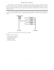
Topics: Power in <strong>AC</strong> circuits<br />
Questions: 1 through 20<br />
Lab Exercise: Lissajous figures for phase shift measurement (question 71)<br />
Topics: Power factor correction<br />
Questions: 21 through 40<br />
Lab Exercise: Power factor correction for <strong>AC</strong> motor (question 72)<br />
Topics: Alternator construction and introduction to polyphase <strong>AC</strong><br />
Questions: 41 through 55<br />
Lab Exercise: Power factor correction for <strong>AC</strong> motor (question 72, continued)<br />
Topics: <strong>AC</strong> motor construction and polyphase <strong>AC</strong> circuits<br />
Questions: 56 through 70<br />
Lab Exercise: work on project<br />
Day 5<br />
Exam 2: includes Lissajous figure phase shift measurement performance assessment<br />
Practice and challenge problems<br />
Questions: 74 through the end of the worksheet<br />
Impending deadlines<br />
Project due at end of <strong>ELTR</strong><strong>115</strong>, Section 3<br />
Question 73: Sample project grading criteria<br />
1
<strong>ELTR</strong> <strong>115</strong> (<strong>AC</strong> 2), section 2<br />
Skill standards addressed by this course section<br />
EIA Raising the Standard; Electronics Technician Skills for Today and Tomorrow, June 1994<br />
C Technical Skills – <strong>AC</strong> circuits<br />
C.01 Demonstrate an understanding of sources of electricity in <strong>AC</strong> circuits.<br />
C.04 Demonstrate an understanding of basic motor/generator theory and operation.<br />
C.05 Demonstrate an understanding of measurement of power in <strong>AC</strong> circuits.<br />
C.30 Understand principles and operations of <strong>AC</strong> polyphase circuits.<br />
B Basic and Practical Skills – Communicating on the Job<br />
B.01 Use effective written and other communication skills. Met by group discussion and completion of labwork.<br />
B.03 Employ appropriate skills for gathering and retaining information. Met by research and preparation<br />
prior to group discussion.<br />
B.04 Interpret written, graphic, and oral instructions. Met by completion of labwork.<br />
B.06 Use language appropriate to the situation. Met by group discussion and in explaining completed labwork.<br />
B.07 Participate in meetings in a positive and constructive manner. Met by group discussion.<br />
B.08 Use job-related terminology. Met by group discussion and in explaining completed labwork.<br />
B.10 Document work projects, procedures, tests, and equipment failures. Met by project construction and/or<br />
troubleshooting assessments.<br />
C Basic and Practical Skills – Solving Problems and Critical Thinking<br />
C.01 Identify the problem. Met by research and preparation prior to group discussion.<br />
C.03 Identify available solutions and their impact including evaluating credibility of information, and locating<br />
information. Met by research and preparation prior to group discussion.<br />
C.07 Organize personal workloads. Met by daily labwork, preparatory research, and project management.<br />
C.08 Participate in brainstorming sessions to generate new ideas and solve problems. Met by group discussion.<br />
D Basic and Practical Skills – Reading<br />
D.01 Read and apply various sources of technical information (e.g. manufacturer literature, codes, and<br />
regulations). Met by research and preparation prior to group discussion.<br />
E Basic and Practical Skills – Proficiency in Mathematics<br />
E.01 Determine if a solution is reasonable.<br />
E.02 Demonstrate ability to use a simple electronic calculator.<br />
E.05 Solve problems and [sic] make applications involving integers, fractions, decimals, percentages, and<br />
ratios using order of operations.<br />
E.06 Translate written and/or verbal statements into mathematical expressions.<br />
E.09 Read scale on measurement device(s) and make interpolations where appropriate. Met by oscilloscope<br />
usage.<br />
E.12 Interpret and use tables, charts, maps, and/or graphs.<br />
E.13 Identify patterns, note trends, and/or draw conclusions from tables, charts, maps, and/or graphs.<br />
E.15 Simplify and solve algebraic expressions and formulas.<br />
E.16 Select and use formulas appropriately.<br />
E.17 Understand and use scientific notation.<br />
E.26 Apply Pythagorean theorem.<br />
E.27 Identify basic functions of sine, cosine, and tangent.<br />
E.28 Compute and solve problems using basic trigonometric functions.<br />
F Additional Skills – Electromechanics<br />
B.01e Types of motors.<br />
2
<strong>ELTR</strong> <strong>115</strong> (<strong>AC</strong> 2), section 2<br />
Common areas of confusion for students<br />
Difficult concept: Power factor.<br />
The very idea of such a thing as ”imaginary power” (reactive power) is hard to grasp. Basically, what<br />
we’re talking about here is current in an <strong>AC</strong> circuit that is not contributing to work being done because it is<br />
out of phase with the voltage waveform. Instead of contributing to useful work (energy leaving the circuit),<br />
it merely stores and releases energy from reactive components. In a purely reactive circuit, all power in<br />
the circuit is ”imaginary” and does no useful work. In a purely resistive circuit, all power is ”real” and is<br />
dissipated from the circuit by the resistance (this is also true of motor circuits operating at 100% efficiency,<br />
where energy leaves not in the form of heat but in the form of mechanical work). In all realistic circuits,<br />
power is some combination of ”real” and ”imaginary;” true and reactive.<br />
Difficult concept: Measuring phase shift with an oscilloscope.<br />
Phase shift is not as easy to measure with an oscilloscope as is amplitude or frequency, and it takes<br />
practice to learn. Some students have a tendency to look for memorizable formulae or step-by-step procedures<br />
for doing this rather than to figure out how and why it works. As I am fond of telling my students, memory<br />
will fail you! Understand, don’t memorize! Phase shift measurement is not as difficult as it may look. Once<br />
you figure out the relationship between horizontal divisions on the oscilloscope screen and the period (360 o )<br />
of the waveforms, figuring phase shift is merely a matter of ratio: x divisions of shift is to the number of<br />
divisions per cycle as y degrees of shift is to 360 o .<br />
Difficult concept: Polyphase electric power.<br />
Electrical systems having more than one phase (poly-phase) are tremendously useful and prevalent in<br />
modern industry. The idea of having multiple voltages and currents in a system all out of phase with each<br />
other may seem a little weird and confusing, but it is very necessary to know. Perhaps the best way to grasp<br />
what is going on in these systems is to see a video animation of three-phase power being generated, or a<br />
three-phase motor in action. As I teacher, I like to use blinking Christmas lights or the motion of crowds in<br />
grandstands sequentially waving (”The Wave”) as an illustration of the large-scale ”motion” one may create<br />
with out-of-phase sequences.<br />
When it comes to mathematically analyzing what is happening in polyphase systems, phasor diagrams<br />
are most useful. Try to apply a phasor diagram to polyphase problems which you know the solution(s) to,<br />
and then see how the same types of diagrams may apply to problems you are currently trying to solve.<br />
3
Questions<br />
Question 1<br />
Power is easy to calculate in DC circuits. Take for example this DC light bulb circuit:<br />
I = 2.4 A<br />
110 V<br />
Calculate the power dissipation in this circuit, and describe the transfer of energy from source to load:<br />
where does the energy come from and where does it go to?<br />
file 02171<br />
Question 2<br />
A generator is coupled to a bicycle mechanism, so that a person can generate their own electricity:<br />
Generator<br />
Load<br />
The person pedaling this bicycle/generator notices that it becomes more difficult to pedal when the<br />
generator is connected to a load such as a light bulb, or when it is charging a battery. When the generator<br />
is open-circuited, however, it is very easy to spin. Explain why this is, in terms of work and energy transfer.<br />
file 02172<br />
Question 3<br />
If the power waveform is plotted for a resistive <strong>AC</strong> circuit, it will look like this:<br />
i<br />
e<br />
p<br />
e<br />
i<br />
Time<br />
What is the significance of the power value always being positive (above the zero line) and never negative<br />
(below the zero line)?<br />
file 02174<br />
4
Question 4<br />
If the power waveform is plotted for an <strong>AC</strong> circuit with a 90 degree phase shift between voltage and<br />
current, it will look something like this:<br />
e<br />
e<br />
i<br />
i<br />
p<br />
Time<br />
What is the significance of the power value oscillating equally between positive (above the zero line) and<br />
negative (below the zero line)? How does this differ from a scenario where there is zero phase shift between<br />
voltage and current?<br />
file 02175<br />
5
Question 5<br />
If this circuit is built and operated, it will be found that the resistor becomes much hotter than the<br />
inductor, even though both components drop the exact same amount of voltage and carry the exact same<br />
amount of current:<br />
V<br />
V<br />
OFF<br />
A<br />
A<br />
A<br />
COM<br />
Alternator<br />
3.4 Ω<br />
9.02 mH<br />
480 V<strong>AC</strong><br />
60 Hz<br />
V<br />
V<br />
OFF<br />
A<br />
A<br />
A<br />
COM<br />
Explain why there is such a remarkable difference in heat output between these two components, given<br />
their identical voltage drops and currents.<br />
file 02177<br />
Question 6<br />
Calculate the current in this circuit, and also the amount of mechanical power (in units of ”horsepower”)<br />
required to turn this alternator (assume 100% efficiency):<br />
Alternator<br />
3.4 Ω<br />
file 00767<br />
480 V<strong>AC</strong><br />
60 Hz<br />
6
Question 7<br />
Calculate the current in this circuit, and also the amount of mechanical power (in units of ”horsepower”)<br />
required to turn this alternator (assume 100% efficiency):<br />
Alternator<br />
9.02 mH<br />
file 00768<br />
480 V<strong>AC</strong><br />
60 Hz<br />
7
Question 8<br />
A student is pondering the behavior of a simple series RC circuit:<br />
X C = 4 kΩ<br />
4 V<br />
5 V<strong>AC</strong><br />
R = 3 kΩ<br />
3 V<br />
I = 1 mA<br />
It is clear by now that the 4 kΩ capacitive reactance does not directly add to the 3 kΩ resistance to<br />
make 7 kΩ total. Instead, the addition of impedances is vectorial:<br />
√<br />
X C 2 + R 2 = Z total<br />
Z C + Z R = Z total<br />
(4kΩ ̸ − 90 o ) + (3kΩ ̸ 0 o ) = (5kΩ ̸ − 53.13 o )<br />
It is also clear to this student that the component voltage drops form a vectorial sum as well, so that 4<br />
volts dropped across the capacitor in series with 3 volts dropped across the resistor really does add up to 5<br />
volts total source voltage:<br />
V C + V R = V total<br />
(4V ̸ − 90 o ) + (3V ̸ 0 o ) = (5V ̸ − 53.13 o )<br />
What surprises the student, though, is power. In calculating power for each component, the student<br />
arrives at 4 mW for the capacitor (4 volts times 1 milliamp) and 3 mW for the resistor (3 volts times 1<br />
milliamp), but only 5 mW for the total circuit power (5 volts times 1 milliamp). In DC circuits, component<br />
power dissipations always added, no matter how strangely their voltages and currents might be related. The<br />
student honestly expected the total power to be 7 mW, but that doesn’t make sense with 5 volts total voltage<br />
and 1 mA total current.<br />
Then it occurs to the student that power might add vectorially just like impedances and voltage drops.<br />
In fact, this seems to be the only way the numbers make any sense:<br />
P total = 5 mW<br />
P C = 4 mW<br />
P R = 3 mW<br />
However, after plotting this triangle the student is once again beset with doubt. According to the Law<br />
of Energy Conservation, total power in must equal total power out. If the source is inputting 5 mW of power<br />
8
total to this circuit, there should be no possible way that the resistor is dissipating 3 mW and the capacitor<br />
is dissipating 4 mW. That would constitute more energy leaving the circuit than what is entering!<br />
What is wrong with this student’s power triangle diagram? How may we make sense of the figures<br />
obtained by multiplying voltage by current for each component, and for the total circuit?<br />
file 02176<br />
Question 9<br />
The three different types of power in <strong>AC</strong> circuits are as follows:<br />
• S = apparent power, measured in Volt-Amps (VA)<br />
• P = true power, measured in Watts (W)<br />
• Q = reactive power, measured in Volt-Amps reactive (VAR)<br />
Explain the names of each of these power types. Why are they called ”apparent,” ”true,” and ”reactive”?<br />
file 02178<br />
Question 10<br />
Calculate the current in this circuit, and also the amount of mechanical power (in units of ”horsepower”)<br />
required to turn this alternator (assume 100% efficiency):<br />
Alternator<br />
3.4 Ω<br />
9.02 mH<br />
480 V<strong>AC</strong><br />
60 Hz<br />
file 00769<br />
9
Question 11<br />
In this circuit, three common <strong>AC</strong> loads are modeled as resistances, combined with reactive components<br />
in two out of the three cases. Calculate the amount of current registered by each ammeter, and also the<br />
amount of power dissipated by each of the loads:<br />
120 V<strong>AC</strong>, 60 Hz<br />
A A A<br />
10 µF 0.25 H<br />
240 Ω 240 Ω 240 Ω<br />
Fluorescent lamp<br />
Incandescent lamp<br />
Induction motor<br />
If someone were to read each of the ammeters’ indications and multiply the respective currents by the<br />
figure of 120 volts, would the resulting power figures (P = IE) agree with the actual power dissipations?<br />
Explain why or why not, for each load.<br />
file 00770<br />
Question 12<br />
A very important parameter in <strong>AC</strong> power circuits is power factor. Explain what ”power factor” is, and<br />
define its numerical range.<br />
file 02173<br />
Question 13<br />
Power calculation in DC circuits is simple. There are three formulae that may be used to calculate<br />
power:<br />
P = IV P = I 2 R P = V 2<br />
R<br />
Power in DC circuits<br />
Calculating power in <strong>AC</strong> circuits is much more complex, because there are three different types of power:<br />
apparent power (S), true power (P ), and reactive power (Q). Write equations for calculating each of these<br />
types of power in an <strong>AC</strong> circuit:<br />
file 02181<br />
10
Question 14<br />
Calculate the power factor of this circuit:<br />
C = 0.1 µF<br />
32 V<br />
400 Hz<br />
R = 7.1 kΩ<br />
file 02179<br />
Question 15<br />
Explain the difference between a leading power factor and a lagging power factor.<br />
file 00774<br />
Question 16<br />
In this circuit, three common <strong>AC</strong> loads are represented as resistances, combined with reactive components<br />
in two out of the three cases. Calculate the amount of true power (P ), apparent power (S), reactive<br />
power (Q), and power factor (P F ) for each of the loads:<br />
120 V<strong>AC</strong>, 60 Hz<br />
A A A<br />
10 µF 0.25 H<br />
240 Ω 240 Ω 240 Ω<br />
Fluorescent lamp<br />
Incandescent lamp<br />
Induction motor<br />
Also, draw power triangle diagrams for each circuit, showing how the true, apparent, and reactive powers<br />
trigonometrically relate.<br />
file 00772<br />
11
Question 17<br />
Calculate the amount of phase shift between voltage and current in an <strong>AC</strong> circuit with a power factor<br />
of 0.97 (lagging), and an apparent power of 3.5 kVA. Also, write the equation solving for phase shift, in<br />
degrees.<br />
file 00775<br />
Question 18<br />
A common analogy used to describe the different types of power in <strong>AC</strong> circuits is a mug of beer that<br />
also contains foam:<br />
Mug<br />
Foam<br />
Beer<br />
Explain this analogy, relating the quantities of beer and foam to the different types of power in an <strong>AC</strong><br />
circuit, and also why this analogy is often employed to describe the ”desirability” of each power type in a<br />
circuit.<br />
file 00771<br />
12
Question 19<br />
If an electrical device is modeled by fixed values of resistance, inductance, and/or capacitance, it is not<br />
difficult to calculate its power factor:<br />
V<br />
R<br />
L<br />
Electric<br />
motor<br />
(model)<br />
P.F. =<br />
R<br />
√<br />
R2 + (ωL) 2<br />
In real life, though, things are not so simple. An electric motor will not come labeled with an idealcomponent<br />
model expressed in terms of R and L. In fact, that would be impossible, as the resistance R<br />
in the circuit model represents the sum total of mechanical work being done by the motor in addition to<br />
the energy losses. These variables change depending on how heavily loaded the motor is, meaning that the<br />
motor’s power factor will also change with mechanical loading.<br />
However, it may be very important to calculate power factor for electrical loads such as multi-thousand<br />
horsepower electric motors. How is this possible to do when we do not know the equivalent circuit configuration<br />
or values for such a load? In other words, how do we determine the power factor of a real electrical<br />
device as it operates?<br />
. . .<br />
Power conductor<br />
Large electric motor<br />
. . . Power conductor<br />
Of course, there do exist special meters to measure true power (wattmeters) and reactive power (”var”<br />
meters), as well as power factor directly. Unfortunately, these instruments may not be readily available for our<br />
use. What we need is a way to measure power factor using nothing more than standard electrical/electronic<br />
test equipment such as multimeters and oscilloscopes. How may we do this?<br />
Hint: remember that the angle Θ of the S-Q-P ”power triangle” is the same as the angle in a circuit’s<br />
Z-X-R impedance triangle, and also the same as the phase shift angle between total voltage and total<br />
current.<br />
file 02180<br />
13
Question 20<br />
Suppose that a single-phase <strong>AC</strong> electric motor is performing mechanical work at a rate of 45 horsepower.<br />
This equates to 33.57 kW of power, given the equivalence of watts to horsepower (1 HP ≈ 746 W).<br />
Calculate the amount of line current necessary to power this motor if the line voltage is 460 volts,<br />
assuming 100% motor efficiency and a power factor of 1.<br />
Now re-calculate the necessary line current for this motor if its power factor drops to 0.65. Assume the<br />
same efficiency (100%) and the same amount of mechanical power (45 HP).<br />
What do these calculations indicate about the importance of maintaining a high power factor value in<br />
an <strong>AC</strong> circuit?<br />
file 02182<br />
14
Question 21<br />
A common feature of oscilloscopes is the X − Y mode, where the vertical and horizontal plot directions<br />
are driven by external signals, rather than only the vertical direction being driven by a measured signal and<br />
the horizontal being driven by the oscilloscope’s internal sweep circuitry:<br />
Time-domain mode<br />
OSCILLOSCOPE<br />
vertical<br />
Y<br />
X-Y mode<br />
OSCILLOSCOPE<br />
vertical<br />
Y<br />
V/div<br />
DC<br />
GND<br />
<strong>AC</strong><br />
V/div<br />
DC<br />
GND<br />
<strong>AC</strong><br />
trigger<br />
trigger<br />
timebase<br />
X<br />
timebase<br />
X<br />
s/div<br />
X-Y<br />
DC GND <strong>AC</strong><br />
s/div<br />
X-Y<br />
DC GND <strong>AC</strong><br />
<strong>AC</strong> signal<br />
source<br />
<strong>AC</strong> signal<br />
source<br />
<strong>AC</strong> signal<br />
source<br />
<strong>AC</strong> signal<br />
source<br />
The oval pattern shown in the right-hand oscilloscope display of the above illustration is typical for two<br />
sinusoidal waveforms of the same frequency, but slightly out of phase with one another. The technical name<br />
for this type of X − Y plot is a Lissajous figure.<br />
What should the Lissajous figure look like for two sinusoidal waveforms that are at exactly the same<br />
frequency, and exactly the same phase (0 degrees phase shift between the two)? What should the Lissajous<br />
figure look like for two sinusoidal waveforms that are exactly 90 degrees out of phase?<br />
A good way to answer each of these questions is to plot the specified waveforms over time on graph<br />
paper, then determine their instantaneous amplitudes at equal time intervals, and then determine where<br />
that would place the ”dot” on the oscilloscope screen at those points in time, in X − Y mode. To help you,<br />
I’ll provide two blank oscilloscope displays for you to draw the Lissajous figures on:<br />
0 degrees phase shift 90 degrees phase shift<br />
15
file 01480<br />
Question 22<br />
Lissajous figures, drawn by an oscilloscope, are a powerful tool for visualizing the phase relationship<br />
between two waveforms. In fact, there is a mathematical formula for calculating the amount of phase shift<br />
between two sinusoidal signals, given a couple of dimensional measurements of the figure on the oscilloscope<br />
screen.<br />
The procedure begins with adjusting the vertical and horizontal amplitude controls so that the Lissajous<br />
figure is proportional: just as tall as it is wide on the screen (n). Then, we make sure the figure is centered<br />
on the screen and we take a measurement of the distance between the x-axis intercept points (m), as such:<br />
m<br />
n<br />
n<br />
Determine what the formula is for calculating the phase shift angle for this circuit, given these dimensions.<br />
Hint: the formula is trigonometric! If you don’t know where to begin, recall what the respective<br />
Lissajous figures look like for a 0 o phase shift and for a 90 o phase shift, and work from there.<br />
file 01481<br />
16
Question 23<br />
An oscilloscope is connected to a low-current <strong>AC</strong> motor circuit to measure both voltage and current,<br />
and plot them against one another as a Lissajous figure:<br />
<strong>AC</strong> motor<br />
R shunt<br />
Volts/Div A<br />
0.5 0.2 0.1<br />
50 m<br />
1<br />
Position<br />
20 m<br />
2<br />
5<br />
10 m<br />
10<br />
5 m<br />
20<br />
2 m<br />
DC Gnd <strong>AC</strong><br />
A B Alt Chop Add<br />
Volts/Div B<br />
0.5 0.2 0.1<br />
1<br />
50 m<br />
Position<br />
2<br />
20 m<br />
5<br />
10 m<br />
Invert<br />
10<br />
5 m<br />
Intensity Focus Beam find<br />
20<br />
2 m<br />
DC Gnd <strong>AC</strong> Off<br />
Cal 1 V Gnd Trace rot.<br />
Norm<br />
Auto<br />
Single<br />
Reset<br />
Sec/Div<br />
250 µ<br />
1 m 50 µ10<br />
5 m<br />
µ<br />
25 m<br />
2.5 µ<br />
100 m<br />
0.5 µ<br />
500 m<br />
0.1 µ<br />
1<br />
0.025 µ<br />
2.5 off<br />
X-Y<br />
Position<br />
Triggering Level<br />
A<br />
B<br />
Alt Holdoff<br />
Line<br />
Ext.<br />
Ext. input<br />
<strong>AC</strong><br />
DC<br />
LF Rej<br />
Slope<br />
HF Rej<br />
The following Lissajous figure is obtained from this measurement:<br />
From this figure, calculate the phase angle (Θ) and the power factor for this motor circuit.<br />
file 02183<br />
17
Question 24<br />
A very high-power <strong>AC</strong> electric motor needs to have its power factor measured. You and an electrician<br />
are asked to perform this measurement using an oscilloscope. The electrician understands what must be<br />
done to measure voltage and current in this dangerous circuit, and you understand how to interpret the<br />
oscilloscope’s image to calculate power factor.<br />
It would be impractical to directly measure voltage and current, seeing as how the voltage is 4160 volts<br />
<strong>AC</strong> and the current is in excess of 200 amps. Fortunately, PT (”potential transformer”) and CT (”current<br />
transformer”) units are already installed in the motor circuit to facilitate measurements:<br />
CT<br />
power conductor<br />
PT<br />
R shunt<br />
A B Alt Chop Add<br />
Volts/Div A<br />
2<br />
5<br />
1<br />
0.5 0.2 0.1<br />
50 m<br />
20 m<br />
10 m<br />
Position<br />
Sec/Div<br />
250 µ<br />
1 m 50 µ10<br />
5 m<br />
µ<br />
25 m<br />
2.5 µ<br />
100 m<br />
0.5 µ<br />
10<br />
20<br />
2 m<br />
5 m<br />
DC Gnd <strong>AC</strong><br />
500 m<br />
1<br />
2.5<br />
X-Y<br />
0.1 µ<br />
0.025 µ<br />
off<br />
Position<br />
Volts/Div B<br />
0.5 0.2 0.1<br />
1<br />
50 m<br />
Position<br />
2<br />
20 m<br />
5<br />
10 m<br />
Invert<br />
10<br />
5 m<br />
Intensity Focus Beam find<br />
20<br />
2 m<br />
DC Gnd <strong>AC</strong> Off<br />
Cal 1 V Gnd Trace rot.<br />
Norm<br />
Auto<br />
Single<br />
Reset<br />
Triggering Level<br />
A<br />
B<br />
Alt Holdoff<br />
Line<br />
Ext.<br />
Ext. input<br />
<strong>AC</strong><br />
DC<br />
LF Rej<br />
Slope<br />
HF Rej<br />
After the electrician helps you safely connect to the PT and CT units, you obtain a Lissajous figure<br />
that looks like this:<br />
Calculate the power factor of the <strong>AC</strong> motor from this oscilloscope display.<br />
file 02185<br />
18
Question 25<br />
A large electrical load is outfitted with a wattmeter to measure its true power. If the load voltage is 7.2<br />
kV and the load current is 24 amps, calculate the load’s apparent power (S). Calculate the power factor and<br />
also the phase angle between voltage and current in the circuit if the wattmeter registers 155 kW at those<br />
same voltage and current values.<br />
Draw a ”power triangle” for this circuit, graphically showing the relationships between apparent power,<br />
true power, and phase angle.<br />
file 02187<br />
Question 26<br />
The power factor of this circuit is as low as it can possibly be, 0:<br />
L = 0.25 H<br />
30 V<br />
400 Hz<br />
Calculate the apparent, true, and reactive power for this circuit:<br />
• S =<br />
• P =<br />
• Q =<br />
Now, suppose a capacitor is added in parallel with the inductor:<br />
L = 0.25 H<br />
C = 0.47 µF<br />
30 V<br />
400 Hz<br />
Re-calculate the apparent, true, and reactive power for this circuit with the capacitor connected:<br />
• S =<br />
• P =<br />
• Q =<br />
file 02186<br />
19
Question 27<br />
Calculate the line current and power factor in this <strong>AC</strong> power system:<br />
Ammeter<br />
A<br />
240 V<strong>AC</strong><br />
60 Hz<br />
Z = 5 Ω ∠ 34 o<br />
Now, calculate the line current and power factor for the same circuit after the addition of a capacitor<br />
in parallel with the load:<br />
Ammeter<br />
A<br />
240 V<strong>AC</strong><br />
60 Hz<br />
270 µF Z = 5 Ω ∠ 34 o<br />
file 00643<br />
Question 28<br />
It is in the best interest of power distribution systems to maintain the power factors of distant loads as<br />
close to unity (1) as possible. Explain why.<br />
file 01885<br />
Question 29<br />
The ”power triangle” is a very useful model for understanding the mathematical relationship between<br />
apparent power (S), true power (P ), and reactive power (Q):<br />
S<br />
Q<br />
θ<br />
Explain what happens to the triangle if power factor correction components are added to a circuit.<br />
What side(s) change length on the triangle, and what happens to the angle Θ?<br />
file 02184<br />
P<br />
20
Question 30<br />
When a capacitor is to be connected in parallel with an inductive <strong>AC</strong> load to correct for lagging power<br />
factor, it is important to be able to calculate the reactive power of the capacitor (Q C ). Write at least one<br />
equation for calculating the reactive power of a capacitor (in VARs) given the capacitor’s reactance (X C ) at<br />
the line frequency.<br />
file 02189<br />
Question 31<br />
An inductive <strong>AC</strong> load draws 13.4 amps of current at a voltage of 208 volts. The phase shift between line<br />
voltage and line current is measured with an oscilloscope, and determined to be 23 o . Calculate the following:<br />
• Apparent power (S) =<br />
• True power (P ) =<br />
• Reactive power (Q) =<br />
• Power factor =<br />
An electrician suggests to you that the lagging power factor may be corrected by connecting a capacitor<br />
in parallel with this load. If the capacitor is sized just right, it will exactly offset the reactive power of the<br />
inductive load, resulting in zero total reactive power and a power factor of unity (1). Calculate the size of<br />
the necessary capacitor in Farads, assuming a line frequency of 60 Hz.<br />
file 02168<br />
Question 32<br />
An <strong>AC</strong> load exhibits a lagging power factor of 0.73 at 230 V<strong>AC</strong> and 315 amps. If the system frequency<br />
is 60 Hz, calculate the following:<br />
• Apparent power (S) =<br />
• True power (P ) =<br />
• Reactive power (Q) =<br />
• Θ =<br />
• Necessary parallel C size to correct power factor to unity =<br />
file 02191<br />
Question 33<br />
An inductive <strong>AC</strong> load consumes 15.2 MW of true power at a voltage of <strong>115</strong> kV and 149.8 amps. If the<br />
system frequency is 50 Hz, calculate the following:<br />
• Apparent power (S) =<br />
• Reactive power (Q) =<br />
• Power factor =<br />
• Θ =<br />
• Necessary parallel C size to correct power factor to unity =<br />
file 02190<br />
21
Question 34<br />
A dual-trace oscilloscope is used to measure the phase shift between voltage and current for an inductive<br />
<strong>AC</strong> load:<br />
Calculate the following, given a load voltage of 110 volts, a load current of 3.2 amps, and a frequency<br />
of 60 Hz:<br />
• Apparent power (S) =<br />
• True power (P ) =<br />
• Reactive power (Q) =<br />
• Θ =<br />
• Power factor =<br />
• Necessary parallel C size to correct power factor to unity =<br />
file 02192<br />
Question 35<br />
Calculate the power factor of this circuit:<br />
Alternator<br />
3.4 Ω<br />
9.02 mH<br />
480 V<strong>AC</strong><br />
60 Hz<br />
Then, calculate the size of the capacitor necessary to ”correct” the power factor to a value of 1.0, showing<br />
the best location of the capacitor in the circuit.<br />
file 00776<br />
22
Question 36<br />
If an <strong>AC</strong> circuit has a lagging power factor, the way to correct for that power factor is to add a capacitor<br />
to the circuit to create leading reactive power. This leading reactive power will cancel the lagging reactive<br />
power of the load, ideally negating one another so that there is no reactive power demands placed on the<br />
source (zero net reactive power in the circuit):<br />
Inductive<br />
load<br />
C compensation<br />
Define a step-by-step procedure for calculating the size of compensating capacitor needed (in Farads)<br />
in order to correct any lagging power factor to a value of unity. Make your procedure general enough that<br />
it may apply to any scenario.<br />
file 02188<br />
Question 37<br />
Most methods of power factor correction involve the connection of a parallel capacitance to an inductive<br />
load:<br />
R<br />
X L<br />
Inductive<br />
load<br />
C correction<br />
It is technically possible to correct for lagging power factor by connecting a capacitor in series with an<br />
inductive load as well, but this is rarely done:<br />
C correction<br />
R<br />
Inductive<br />
load<br />
X L<br />
Explain why series capacitance is not considered a practical solution for power factor correction in most<br />
applications.<br />
file 02195<br />
23
Question 38<br />
Although most high-power <strong>AC</strong> loads are inductive in nature, some are capacitive. Explain what you<br />
would have to do to correct for the leading power factor of a large capacitive load, provided the power factor<br />
were low enough to warrant the expense of equipment to correct it.<br />
file 02193<br />
Question 39<br />
In <strong>AC</strong> power systems, a common way of thinking about reactive power among engineers is in terms of<br />
production and consumption. Inductive loads, it is said, consume reactive power. Conversely, capacitive<br />
loads produce reactive power.<br />
Explain how the models of ”production” and ”consumption” relate to reactive power in capacitors and<br />
inductors, respectively. Being that neither type of component actually dissipates or generates electrical<br />
energy, how can these terms be appropriate in describing their behavior?<br />
file 00773<br />
Question 40<br />
Another name for ”capacitor” is condenser. Explain what a synchronous condenser is, and how it is<br />
used to correct power factor in <strong>AC</strong> power systems.<br />
file 02194<br />
Question 41<br />
Which magnet motion past the wire will produce the greatest voltmeter indication: perpendicular,<br />
parallel, or no motion at all?<br />
motion<br />
motion +<br />
magnet<br />
+<br />
V<br />
-<br />
magnet<br />
V<br />
-<br />
no motion<br />
magnet<br />
+<br />
V<br />
-<br />
file 00174<br />
24
Question 42<br />
We know that in order to induce a sinusoidal voltage in a wire coil, the magnetic flux linking the turns<br />
of wire in the coil must follow a sinusoidal path over time, phase-shifted 90 o from the voltage waveform.<br />
This relationship between flux and induced voltage is expressed in Faraday’s equation v = N dφ<br />
dt :<br />
e<br />
φ<br />
Based on this fact, draw the position of the magnetic rotor in this alternator when the voltage is at one<br />
of its peaks:<br />
N<br />
???<br />
S<br />
file 00818<br />
25
Question 43<br />
Describe the nature of the voltage induced in the stationary (”stator”) windings, as the permanent<br />
magnet rotor rotates in this machine:<br />
iron<br />
N<br />
S<br />
wire<br />
wire<br />
What factors determine the magnitude of this voltage? According to Faraday’s Law, what factors can<br />
we alter to increase the voltage output by this generator?<br />
Is the induced voltage <strong>AC</strong> or DC? How can you tell?<br />
file 00816<br />
Question 44<br />
In order to make the most practical <strong>AC</strong> generator (or alternator, as it is also known), which design makes<br />
more sense: a stationary permanent magnet with a rotating wire coil, or a rotating permanent magnet with<br />
a stationary wire coil? Explain your choice.<br />
file 00817<br />
26
Question 45<br />
If this alternator is spun at 4500 RPM (revolutions per minute), what will be the frequency of its output<br />
voltage?<br />
N<br />
S<br />
Hint: how many cycles of <strong>AC</strong> are produced for every revolution of the rotor?<br />
file 00819<br />
Question 46<br />
How fast must a 12-pole alternator spin in order to produce 60 Hz <strong>AC</strong> power? Write a mathematical<br />
equation solving for speed (S) in terms of frequency (f) and the number of poles (N).<br />
file 00821<br />
Question 47<br />
How many poles does an alternator have if it generates 400 Hz power at a shaft speed of 6000 RPM?<br />
file 02196<br />
Question 48<br />
Assuming that the output frequency of an alternator must remain constant (as is the case in national<br />
power systems, where the frequency of all power plants must be the same), how may its output voltage be<br />
regulated? In other words, since we do not have the luxury of increasing or decreasing its rotational speed<br />
to control voltage, since that would change the frequency, how can we coax the alternator to produce more<br />
or less voltage on demand?<br />
Hint: automotive alternators are manufactured with this feature, though the purpose in that application<br />
is to maintain constant voltage despite changes in engine speed. In automotive electrical systems, the<br />
frequency of the alternator’s output is irrelevant because the <strong>AC</strong> is ”rectified” into DC (frequency = 0 Hz)<br />
to charge the battery.<br />
file 00820<br />
27
Question 49<br />
Suppose a set of three neon light bulbs were connected to an alternator with three sets of windings<br />
labeled A, B, and C:<br />
A<br />
A<br />
B<br />
C<br />
N<br />
S<br />
B<br />
C<br />
B<br />
C<br />
B<br />
A<br />
A<br />
C<br />
The schematic diagram for this alternator/lamp system is as follows:<br />
A B C<br />
C<br />
B<br />
A<br />
Alternator<br />
If the alternator spins fast enough (clockwise, as shown), the <strong>AC</strong> voltage induced in its windings will<br />
be enough to cause the neon lamps to ”blink” (neon bulbs have very fast reaction times and thus cannot<br />
maintain a glow for very long without current, unlike incandescent lamps which operate on the principle of<br />
a glowing-hot metal filament). Most likely this blinking will be too fast to discern with the naked eye.<br />
However, if we were to videorecord the blinking and play back the recording at a slow speed, we should<br />
be able to see the sequence of light flashes. Determine the apparent ”direction” of the lamps’ blinking (from<br />
right-to-left or from left-to-right), and relate that sequence to the voltage peaks of each alternator coil pair.<br />
file 02198<br />
28
Question 50<br />
Suppose we have an alternator with two sets of windings, A and B:<br />
B<br />
A<br />
N<br />
S<br />
A<br />
B<br />
Each pair of windings in each set is series-connected, so they act as just two separate windings:<br />
A<br />
B<br />
If one end of each winding pair were connected together at a common ground point, and each winding<br />
pair output 70 volts RMS, how much voltage would be measured between the open winding pair ends?<br />
V = ???<br />
70 V RMS 70 V RMS<br />
file 01886<br />
29
Question 51<br />
Suppose we have an alternator with three sets of windings, A, B, and C:<br />
A<br />
B<br />
C<br />
N<br />
S<br />
C<br />
B<br />
A<br />
Each pair of windings in each set is series-connected, so they act as just three separate windings (pay<br />
close attention to the phase-marking dots!):<br />
A B C<br />
If one end of each winding pair were connected together at a common ground point, and each winding<br />
pair output 70 volts RMS, how much voltage would be measured between any two open wires?<br />
V = ???<br />
70 V RMS<br />
file 01887<br />
Question 52<br />
What is polyphase electric power, and how does it differ from single-phase power?<br />
file 02197<br />
30
Question 53<br />
Label where each of the following electrical quantities would be found in both the ”Y” and ”Delta”<br />
three-phase configurations:<br />
• Phase voltage<br />
• Line voltage<br />
• Phase current<br />
• Line current<br />
In which circuit (Y or Delta) are the phase and line currents equal? In which circuit (Y or Delta) are<br />
the phase and line voltages equal? Explain both answers, in terms that anyone with a basic knowledge of<br />
electricity could understand.<br />
Where phase and line quantities are unequal, determine which is larger.<br />
file 02201<br />
31
Question 54<br />
This is a schematic diagram of a Y-connected three-phase generator (with the rotor winding shown):<br />
Three-phase "Y" alternator<br />
A<br />
B<br />
. . . to a threephase<br />
load<br />
C<br />
Rotor winding<br />
How much <strong>AC</strong> voltage will appear between any two of the lines (V AB , V BC , or V <strong>AC</strong> ) if each stator coil<br />
inside the alternator outputs 277 volts? Draw a phasor diagram showing how the phase (winding) and line<br />
voltages relate.<br />
file 02199<br />
Question 55<br />
This is a schematic diagram of a Delta-connected three-phase generator (with the rotor winding shown):<br />
Three-phase "Delta" alternator<br />
A<br />
B<br />
. . . to a threephase<br />
load<br />
C<br />
Rotor winding<br />
How much <strong>AC</strong> current will each of the lines (I A , I B , or I C ) conduct to a load (not shown) if each stator<br />
coil inside the alternator outputs 17 amps of current?<br />
file 02200<br />
32
Question 56<br />
If a copper ring is brought closer to the end of a permanent magnet, a repulsive force will develop<br />
between the magnet and the ring. This force will cease, however, when the ring stops moving. What is this<br />
effect called?<br />
Motion<br />
Reaction<br />
N<br />
Magnet<br />
S<br />
force<br />
Also, describe what will happen if the copper ring is moved away from the end of the permanent magnet.<br />
file 00254<br />
Question 57<br />
If a closed-circuit wire coil is brought closer to the end of a permanent magnet, a repulsive force will<br />
develop between the magnet and the coil. This force will cease, however, when the coil stops moving. What<br />
is this effect called?<br />
Coil motion<br />
Reaction<br />
N<br />
Magnet<br />
S<br />
force<br />
Closed-circuit<br />
wire coil<br />
Also, describe what will happen if the wire coil fails open. Does the same effect persist? Why or why<br />
not?<br />
file 00735<br />
33
Question 58<br />
Electromechanical watt-hour meters use an aluminum disk that is spun by an electric motor. To generate<br />
a constant ”drag” on the disk necessary to limit its rotational speed, a strong magnet is placed in such a<br />
way that its lines of magnetic flux pass perpendicularly through the disk’s thickness:<br />
N<br />
shaft<br />
S<br />
Aluminum disk<br />
The disk itself need not be made of a ferromagnetic material in order for the magnet to create a ”drag”<br />
force. It simply needs to be a good conductor of electricity.<br />
Explain the phenomenon accounting for the drag effect, and also explain what would happen if the roles<br />
of magnet and disk were reversed: if the magnet were moved in a circle around the periphery of a stationary<br />
disk.<br />
file 00745<br />
Question 59<br />
A technique commonly used in special-effects lighting is to sequence the on/off blinking of a string of<br />
light bulbs, to produce the effect of motion without any moving objects:<br />
all "1" bulbs lit<br />
1 2 3 1 2 3 1 2 3 1 2 3<br />
all "2" bulbs lit<br />
all "3" bulbs lit<br />
1 2 3 1 2 3 1 2 3 1 2 3<br />
1 2 3 1 2 3 1 2 3 1 2 3<br />
Time<br />
all "1" bulbs lit<br />
1 2 3 1 2 3 1 2 3 1 2 3<br />
phase sequence = 1-2-3<br />
bulbs appear to be "moving" from left to right<br />
What would the effect be if this string of lights were arranged in a circle instead of a line? Also, explain<br />
what would have to change electrically to alter the ”speed” of the blinking lights’ ”motion”.<br />
file 00734<br />
34
Question 60<br />
If a set of six electromagnet coils were spaced around the periphery of a circle and energized by 3-phase<br />
<strong>AC</strong> power, what would a magnetic compass do that was placed in the center?<br />
Physical arrangement of coils<br />
Coil<br />
1a<br />
Coil connection pattern<br />
Coil<br />
2a<br />
Coil<br />
3b<br />
Coil<br />
1a<br />
Coil<br />
3a<br />
Compass<br />
Coil<br />
2b<br />
Coil<br />
2b<br />
Coil<br />
2a<br />
Coil<br />
1b<br />
Coil<br />
3a<br />
Coil<br />
3b<br />
Coil<br />
1b<br />
Hint: imagine the electromagnets were light bulbs instead, and the frequency of the <strong>AC</strong> power was slow<br />
enough to see each light bulb cycle in brightness, from fully dark to fully bright and back again. What would<br />
the pattern of lights appear to do?<br />
file 00737<br />
35
Question 61<br />
Explain what will happen to the unmagnetized rotor when 3-phase <strong>AC</strong> power is applied to the stationary<br />
electromagnet coils. Note that the rotor is actually a short-circuited electromagnet:<br />
Physical arrangement of coils<br />
Coil<br />
1a<br />
Coil connection pattern<br />
Coil<br />
2a<br />
Coil<br />
3b<br />
Coil<br />
1a<br />
Coil<br />
3a<br />
Coil<br />
2b<br />
Coil<br />
2b<br />
Coil<br />
2a<br />
Coil<br />
1b<br />
Coil<br />
3a<br />
Coil<br />
3b<br />
Coil<br />
1b<br />
file 00739<br />
36
Question 62<br />
These two electric motor designs are quite similar in appearance, but differ in the specific principle that<br />
makes the rotor move:<br />
Induction motor<br />
Coil<br />
1a<br />
Synchronous motor<br />
Coil<br />
1a<br />
Coil<br />
2a<br />
Coil<br />
3b<br />
Coil<br />
2a<br />
N<br />
Coil<br />
3b<br />
Coil<br />
3a<br />
Coil<br />
2b<br />
Coil<br />
3a<br />
S<br />
Coil<br />
2b<br />
Coil<br />
1b<br />
Coil<br />
1b<br />
Synchronous <strong>AC</strong> motors use a permanent magnet rotor, while induction motors use an electromagnet<br />
rotor. Explain what practical difference this makes in each motor’s operation, and also explain the meaning<br />
of the motors’ names. Why is one called ”synchronous” and the other called ”induction”?<br />
file 00740<br />
Question 63<br />
What would we have to do in order to reverse the rotation of this three-phase induction motor?<br />
Connection terminals<br />
On/off switch<br />
From 3-phase<br />
power source<br />
motor<br />
Explain your answer. Describe how the (simple) solution to this problem works.<br />
file 00415<br />
37
Question 64<br />
Suppose an induction motor were built to run on single-phase <strong>AC</strong> power rather than polyphase <strong>AC</strong><br />
power. Instead of multiple sets of windings, it only has one set of windings:<br />
Coil<br />
1a<br />
Coil<br />
1b<br />
Which way would the rotor start to spin as power is applied?<br />
file 00743<br />
38
Question 65<br />
Calculate all voltages, currents, and total power in this balanced Delta-Delta system:<br />
Source<br />
Load<br />
230 V<br />
50 Ω<br />
E line =<br />
I line =<br />
E phase(source) =<br />
I phase(source) =<br />
E phase(load) =<br />
I phase(load) =<br />
P total =<br />
file 02203<br />
Question 66<br />
Calculate all voltages, currents, and total power in this balanced Y-Y system:<br />
Source<br />
Load<br />
1.5 kΩ<br />
13.8 kV<br />
E line =<br />
I line =<br />
E phase(source) =<br />
I phase(source) =<br />
E phase(load) =<br />
I phase(load) =<br />
P total =<br />
file 02202<br />
39
Question 67<br />
Calculate all voltages, currents, and total power in this balanced Delta-Y system:<br />
Source<br />
Load<br />
2400 V<br />
300 Ω<br />
E line =<br />
I line =<br />
E phase(source) =<br />
I phase(source) =<br />
E phase(load) =<br />
I phase(load) =<br />
P total =<br />
file 00428<br />
Question 68<br />
Calculate all voltages, currents, and total power in this balanced Y-Delta system:<br />
Source<br />
Load<br />
120 V<br />
580 Ω<br />
E line =<br />
I line =<br />
E phase(source) =<br />
I phase(source) =<br />
E phase(load) =<br />
I phase(load) =<br />
P total =<br />
file 02204<br />
40
Question 69<br />
The line voltage to this three-phase load is 480 volts. How much power (total) is dissipated by the load?<br />
How much current is there in each line supplying the load?<br />
E line = 480 V<strong>AC</strong><br />
25 Ω<br />
25 Ω 25 Ω<br />
One more question: write an equation for calculating power in a balanced, three-phase circuit, given<br />
line voltage and line current only.<br />
file 00421<br />
Question 70<br />
A balanced, three-phase power system has a line voltage of 13.8 kV volts and a line current of 150 amps.<br />
How much power is being delivered to the load (assuming a power factor of 1)?<br />
E line = 13.8 kV<br />
I line = 150 A<br />
3-phase<br />
source<br />
3-phase<br />
load<br />
Lines<br />
A 13.8 kV single-phase system could be designed to provide the same amount of power to a load, but<br />
it would require heavier-gauge (more expensive!) conductors. Determine the extra percentage of expense in<br />
wire cost (based on the weight of the wires) resulting from the use of single-phase instead of three-phase.<br />
Single-phase<br />
source<br />
E line = 13.8 kV<br />
Single-phase<br />
load<br />
Lines<br />
file 00414<br />
41
Question 71<br />
Competency: Lissajous figures for phase shift measurement<br />
Schematic<br />
Volts/Div A<br />
0.5 0.2 0.1<br />
1<br />
50 m<br />
2<br />
20 m Position<br />
5<br />
10 m<br />
Version:<br />
Sec/Div<br />
250 µ<br />
1 m 50 µ10<br />
5 m<br />
µ<br />
25 m<br />
2.5 µ<br />
100 m<br />
0.5 µ<br />
10<br />
5 m<br />
20<br />
2 m<br />
DC Gnd <strong>AC</strong><br />
C 1<br />
A B Alt Chop Add<br />
R 1<br />
500 m<br />
1<br />
2.5<br />
X-Y<br />
0.1 µ<br />
0.025 µ<br />
off<br />
Position<br />
Volts/Div B<br />
0.5 0.2 0.1<br />
1<br />
50 m<br />
Position<br />
2<br />
20 m<br />
5<br />
10 m<br />
Invert<br />
10<br />
5 m<br />
Intensity Focus Beam find<br />
20<br />
2 m<br />
DC Gnd <strong>AC</strong> Off<br />
Cal 1 V Gnd Trace rot.<br />
Norm<br />
Auto<br />
Single<br />
Reset<br />
Triggering Level<br />
A<br />
B<br />
Alt Holdoff<br />
Line<br />
Ext.<br />
Ext. input<br />
<strong>AC</strong><br />
DC<br />
LF Rej<br />
Slope<br />
HF Rej<br />
Given conditions<br />
f supply =<br />
C 1 = R 1 =<br />
Parameters<br />
Predicted<br />
Lissajous figure (measured)<br />
θ<br />
n (Divisions)<br />
Measured<br />
m (Divisions)<br />
θ<br />
n<br />
m<br />
n<br />
file 01676<br />
42
Question 72<br />
Competency: Power factor correction for <strong>AC</strong> motor<br />
Schematic<br />
C 1<br />
Version:<br />
Oscilloscope channel 2 here<br />
(×10 probe recommended)<br />
<strong>AC</strong> induction<br />
motor<br />
Oscilloscope<br />
ground here<br />
Given conditions<br />
R shunt<br />
Oscilloscope channel 1 here<br />
Voltage/current display on scope<br />
Volts/div =<br />
Sec/div =<br />
R shunt =<br />
Parameters<br />
(Without C 1 )<br />
Measured<br />
(With C 1 connected)<br />
Measured<br />
θ<br />
C 1<br />
Predicted<br />
I total<br />
To correct P.F. to<br />
a value of unity<br />
file 01685<br />
43
Question 73<br />
NAME: Project Grading Criteria PROJECT:<br />
You will receive the highest score for which all criteria are met.<br />
100 % (Must meet or exceed all criteria listed)<br />
A. Impeccable craftsmanship, comparable to that of a professional assembly<br />
B. No spelling or grammatical errors anywhere in any document, upon first submission to instructor<br />
95 % (Must meet or exceed these criteria in addition to all criteria for 90% and below)<br />
A. Technical explanation sufficiently detailed to teach from, inclusive of every component (supersedes 75.B)<br />
B. Itemized parts list complete with part numbers, manufacturers, and (equivalent) prices for all components,<br />
including recycled components and parts kit components (supersedes 90.A)<br />
90 % (Must meet or exceed these criteria in addition to all criteria for 85% and below)<br />
A. Itemized parts list complete with prices of components purchased for the project, plus total price<br />
B. No spelling or grammatical errors anywhere in any document upon final submission<br />
85 % (Must meet or exceed these criteria in addition to all criteria for 80% and below)<br />
A. “User’s guide” to project function (in addition to 75.B)<br />
B. Troubleshooting log describing all obstacles overcome during development and construction<br />
80 % (Must meet or exceed these criteria in addition to all criteria for 75% and below)<br />
A. All controls (switches, knobs, etc.) clearly and neatly labeled<br />
B. All documentation created on computer, not hand-written (including the schematic diagram)<br />
75 % (Must meet or exceed these criteria in addition to all criteria for 70% and below)<br />
A. Stranded wire used wherever wires are subject to vibration or bending<br />
B. Basic technical explanation of all major circuit sections<br />
C. Deadline met for working prototype of circuit (Date/Time = / )<br />
70 % (Must meet or exceed these criteria in addition to all criteria for 65%)<br />
A. All wire connections sound (solder joints, wire-wrap, terminal strips, and lugs are all connected properly)<br />
B. No use of glue where a fastener would be more appropriate<br />
C. Deadline met for submission of fully-functional project (Date/Time = / ) –<br />
supersedes 75.C if final project submitted by that (earlier) deadline<br />
65 % (Must meet or exceed these criteria in addition to all criteria for 60%)<br />
A. Project fully functional<br />
B. All components securely fastened so nothing is “loose” inside the enclosure<br />
C. Schematic diagram of circuit<br />
60 % (Must meet or exceed these criteria in addition to being safe and legal)<br />
A. Project minimally functional, with all components located inside an enclosure (if applicable)<br />
B. Passes final safety inspection (proper case grounding, line power fusing, power cords strain-relieved)<br />
0 % (If any of the following conditions are true)<br />
A. Fails final safety inspection (improper grounding, fusing, and/or power cord strain relieving)<br />
B. Intended project function poses a safety hazard<br />
C. Project function violates any law, ordinance, or school policy<br />
file 03173<br />
44
Question 74<br />
If a sinusoidal voltage is applied to an impedance with a phase angle of 0 o , the resulting voltage and<br />
current waveforms will look like this:<br />
e<br />
e<br />
i<br />
i<br />
Time<br />
Given that power is the product of voltage and current (p = ie), plot the waveform for power in this<br />
circuit.<br />
file 00631<br />
Question 75<br />
If a sinusoidal voltage is applied to an impedance with a phase angle of 90 o , the resulting voltage and<br />
current waveforms will look like this:<br />
e<br />
i<br />
e<br />
i<br />
Time<br />
Given that power is the product of voltage and current (p = ie), plot the waveform for power in this<br />
circuit. Also, explain how the mnemonic phrase ”ELI the ICE man” applies to these waveforms.<br />
file 00632<br />
45
Question 76<br />
If a sinusoidal voltage is applied to an impedance with a phase angle of -90 o , the resulting voltage and<br />
current waveforms will look like this:<br />
e<br />
e<br />
i<br />
i<br />
Time<br />
Given that power is the product of voltage and current (p = ie), plot the waveform for power in this<br />
circuit. Also, explain how the mnemonic phrase ”ELI the ICE man” applies to these waveforms.<br />
file 00633<br />
Question 77<br />
In this graph of two <strong>AC</strong> voltages, which one is leading and which one is lagging?<br />
+5<br />
+4<br />
+3<br />
+2<br />
+1<br />
V<br />
0<br />
-1<br />
-2<br />
-3<br />
-4<br />
-5<br />
If the 4-volt (peak) sine wave is denoted in phasor notation as 4 V̸ 0 o , how should the 3-volt (peak)<br />
waveform be denoted? Express your answer in both polar and rectangular forms.<br />
If the 4-volt (peak) sine wave is denoted in phasor notation as 4 V̸ 90 o , how should the 3-volt (peak)<br />
waveform be denoted? Express your answer in both polar and rectangular forms.<br />
file 00499<br />
46
Question 78<br />
In this phasor diagram, determine which phasor is leading and which is lagging the other:<br />
B<br />
A<br />
file 03286<br />
Question 79<br />
Large power distribution centers are often equipped with capacitors to correct for lagging (inductive)<br />
power factor of many industrial loads. There is never any one value for capacitance that will precisely<br />
correct for the power factor, though, because load conditions constantly change. At first it may seem that<br />
a variable capacitor would be the answer (adjustable to compensate for any value of lagging power factor),<br />
but variable capacitors with the ratings necessary for power line compensation would be prohibitively large<br />
and expensive.<br />
One solution to this problem of variable capacitance uses a set of electromechanical relays with fixedvalue<br />
capacitors:<br />
. . .<br />
To <strong>AC</strong> power<br />
lines<br />
. . .<br />
Relay Relay Relay Relay<br />
1 µF 2 µF 4 µF 8 µF<br />
Explain how a circuit such as this provides a step-variable capacitance, and determine the range of<br />
capacitance it can provide.<br />
file 03625<br />
47
Question 80<br />
Lenz’s Law describes the opposition to changes in magnetic flux resulting from electromagnetic induction<br />
between a magnetic field and an electrical conductor. One apparatus capable of demonstrating Lenz’s Law<br />
is a copper or aluminum disk (electrically conductive, but non-magnetic) positioned close to the end of a<br />
powerful permanent magnet. There is no attraction or repulsion between the disk and magnet when there is<br />
no motion, but a force will develop between the two objects if either is suddenly moved. This force will be in<br />
such a direction that it tries to resist the motion (i.e. the force tries to maintain the gap constant between<br />
the two objects):<br />
Motion<br />
N<br />
S<br />
Reaction<br />
force<br />
We know this force is magnetic in nature. That is, the induced current causes the disk itself to become a<br />
magnet in order to react against the permanent magnet’s field and produce the opposing force. For each of<br />
the following scenarios, label the disk’s induced magnetic poles (North and South) as it reacts to the motion<br />
imposed by an outside force:<br />
Figure 1 Figure 2<br />
Motion<br />
Motion<br />
N<br />
S<br />
N<br />
S<br />
Figure 3 Figure 4<br />
Motion<br />
Motion<br />
S<br />
N<br />
S<br />
N<br />
file 01982<br />
48
Question 81<br />
Combining Lenz’s Law with the right-hand rule (or left-hand rule, if you follow electron flow instead of<br />
conventional flow) provides a simple and effective means for determining the direction of induced current in<br />
an induction coil. In the following examples, trace the direction of current through the load resistor:<br />
Motion<br />
Figure 1 Figure 2 Figure 3<br />
S<br />
N<br />
Motion<br />
N<br />
S<br />
Motion<br />
S<br />
N<br />
Motion<br />
Figure 4 Figure 5 Figure 6<br />
N<br />
S<br />
S<br />
N<br />
Motion<br />
N<br />
S<br />
Motion<br />
file 01787<br />
Question 82<br />
Based on your knowledge of Lenz’s Law, explain how one could construct an electromagnetic brake,<br />
whereby the energization of an electromagnet coil would produce mechanical ”drag” on a rotating shaft<br />
without the need for contact between the shaft and a brake pad.<br />
file 01786<br />
49
Question 83<br />
If an electric current is passed through this wire, which direction will the wire be pushed (by the<br />
interaction of the magnetic fields)?<br />
wire<br />
N Magnet S N Magnet<br />
S<br />
+ -<br />
Is this an example of an electric motor or an electric generator?<br />
file 00382<br />
50
Question 84<br />
If this wire (between the magnet poles) is moved in an upward direction, what polarity of voltage will<br />
the meter indicate?<br />
motion<br />
wire<br />
N Magnet S N Magnet<br />
S<br />
A<br />
V Ω<br />
COM<br />
Describe the factors influencing the magnitude of the voltage induced by motion, and determine whether<br />
this is an example of an electric motor or an electric generator.<br />
file 00806<br />
51
Question 85<br />
If this wire (between the magnet poles) is moved in an upward direction, and the wire ends are connected<br />
to a resistive load, which way will current go through the wire?<br />
motion<br />
wire<br />
N Magnet S N Magnet<br />
S<br />
We know that current moving through a wire will create a magnetic field, and that this magnetic field will<br />
produce a reaction force against the static magnetic fields coming from the two permanent magnets. Which<br />
direction will this reaction force push the current-carrying wire? How does the direction of this force relate<br />
to the direction of the wire’s motion? Does this phenomenon relate to any principle of electromagnetism<br />
you’ve learned so far?<br />
file 00807<br />
52
Question 86<br />
Determine the polarity of induced voltage between the ends of this wire loop, as it is rotated between<br />
the two magnets:<br />
N Magnet S N Magnet<br />
S<br />
N Magnet S N Magnet<br />
N Magnet S N Magnet<br />
S<br />
S<br />
sequence over time<br />
N Magnet S N Magnet<br />
S<br />
N Magnet S N Magnet<br />
S<br />
file 00808<br />
53
Question 87<br />
Describe what will happen to a closed-circuit wire coil if it is placed in close proximity to an electromagnet<br />
energized by alternating current:<br />
Also, describe what will happen if the wire coil fails open.<br />
file 00736<br />
Question 88<br />
Closed-circuit<br />
wire coil<br />
Explain what slip speed is for an <strong>AC</strong> induction motor, and why there must be such as thing as ”slip” in<br />
order for an induction motor to generate torque.<br />
file 03216<br />
Question 89<br />
Synchronous <strong>AC</strong> motors operate with zero slip, which is what primarily distinguishes them from induction<br />
motors. Explain what ”slip” means for an induction motor, and why synchronous motors do not have<br />
it.<br />
file 03217<br />
54
Question 90<br />
An interesting variation on the induction motor theme is the wound-rotor induction motor. In the<br />
simplest form of a wound-rotor motor, the rotor’s electromagnet coil terminates on a pair of slip rings which<br />
permit contact with stationary carbon brushes, allowing an external circuit to be connected to the rotor coil:<br />
Wound-rotor induction motor<br />
Coil<br />
1a<br />
Coil<br />
2a<br />
Coil<br />
3b<br />
Coil<br />
3a<br />
Slip<br />
rings<br />
Coil<br />
2b<br />
Coil<br />
1b<br />
Explain how this motor can be operated as either a synchronous motor or a ”plain” induction motor.<br />
file 00741<br />
Question 91<br />
A very common design of <strong>AC</strong> motor is the so-called squirrel cage motor. Describe how a ”squirrel cage”<br />
motor is built, and classify it as either an ”induction” motor or a ”synchronous” motor.<br />
file 00742<br />
Question 92<br />
Describe the operating principles of these three methods for starting single-phase induction motors:<br />
• Shaded pole<br />
• Split-phase, capacitor<br />
• Split-phase (resistor or inductor)<br />
file 00744<br />
55
Question 93<br />
Many single-phase ”squirrel-cage” induction motors use a special start winding which is energized only<br />
at low (or no) speed. When the rotor reaches full operating speed, the starting switch opens to de-energize<br />
the start winding:<br />
. . .<br />
To <strong>AC</strong><br />
power<br />
source<br />
. . .<br />
Speed<br />
switch<br />
Squirrel-cage<br />
induction motor<br />
C<br />
Rotor<br />
Start<br />
winding<br />
Run<br />
winding<br />
Explain why this special winding is necessary for the motor to start, and also why there is a capacitor<br />
connected in series with this start winding. What would happen if the start switch, capacitor, or start<br />
winding were to fail open?<br />
file 03622<br />
56
Question 94<br />
The lines of a three-phase power system may be connected to the terminals of a three-phase motor in<br />
several different ways. Which of these altered motor connections will result in the motor reversing direction?<br />
Original wiring<br />
From 3-phase<br />
power source<br />
motor<br />
Example #1<br />
From 3-phase<br />
power source<br />
motor<br />
Example #2<br />
From 3-phase<br />
power source<br />
motor<br />
Example #3<br />
From 3-phase<br />
power source<br />
motor<br />
file 00419<br />
57
Question 95<br />
Some <strong>AC</strong> induction motors are equipped with multiple windings so they may operate at two distinct<br />
speeds (low speed usually being one-half of high speed). Shown here is the connection diagram for one type<br />
of two-speed motor:<br />
4<br />
3<br />
1<br />
2<br />
5 6<br />
There are six terminals on the motor itself where the connections are made:<br />
Motor<br />
4 5 6<br />
1 2 3<br />
Shaft<br />
The motor’s datasheet will specify how the connections are to be made. This is typical:<br />
Speed φ-A φ-B φ-C Left open Shorted together<br />
Low 1 2 3 4,5,6<br />
High 4 5 6 1,2,3<br />
Explain why the motor runs at half-speed in one connection scheme and full speed in the other. What<br />
is going on that makes this possible?<br />
file 03218<br />
58
Question 96<br />
This electric motor was operating just fine, then one day it mysteriously shut down. The electrician<br />
discovered two blown fuses, which he then replaced:<br />
From 3-phase<br />
power source<br />
blown!<br />
blown!<br />
On/off switch<br />
motor<br />
When the on/off switch was closed again, the motor made a loud ”humming” noise, then became quiet<br />
after a few seconds. It never turned, though. Upon inspection, the electrician discovered the same two fuses<br />
had blown again.<br />
If you were asked to help troubleshoot this electric motor circuit, what would you recommend as the<br />
next step?<br />
file 00422<br />
59
Question 97<br />
Examine this three-phase motor control circuit, where fuses protect against overcurrent and a three-pole<br />
relay (called a contactor) turns power on and off to the motor:<br />
Fuse<br />
Fuse<br />
Fuse<br />
Fuses<br />
Schematic<br />
diagram<br />
1 2 3<br />
1 2 3<br />
motor<br />
Motor<br />
3<br />
2<br />
1<br />
Shaft<br />
1 2 3<br />
Contactor<br />
1 2 3<br />
After years of faithful service, one day this motor refuses to start. It makes a ”humming” sound when the<br />
contactor is energized (relay contacts close), but it does not turn. A mechanic checks it out and determines<br />
that the shaft is not seized, but is free to turn. The problem must be electrical in nature!<br />
You are called to investigate. Using a clamp-on ammeter, you measure the current through each of<br />
the lines (immediately after each fuse) as another start is once again attempted. You then record the three<br />
current measurements:<br />
Line Current<br />
1 52.7 amps<br />
2 51.9 amps<br />
3 0 amps<br />
Determine at least two possible faults which could account for the motor’s refusal to start and the<br />
60
three current measurements taken. Then, decide what your next measurement(s) will be to isolate the exact<br />
location and nature of the fault.<br />
file 03623<br />
Question 98<br />
Working on a job site with an experienced technician, you are tasked with trying to determine whether<br />
the line currents going to a three-phase electric motor are balanced. If everything is okay with the motor<br />
and the power circuitry, of course, the three line currents should be precisely equal to each other.<br />
The problem is, neither of you brought a clamp-on ammeter for measuring the line currents. Your<br />
multimeters are much too small to measure the large currents in this circuit, and connecting an ammeter<br />
in series with such a large motor could be dangerous anyway. So, the experienced technician decides to try<br />
something different – he uses his multimeter as an <strong>AC</strong> milli-voltmeter to measure the small voltage drop<br />
across each fuse, using the fuses as crude shunt resistors:<br />
mV<br />
V<br />
A<br />
Fuse Fuse Fuse<br />
V<br />
OFF<br />
A<br />
A<br />
COM<br />
He obtains the following measurements:<br />
Line Fuse voltage drop<br />
1 24.3 mV<br />
2 37.9 mV<br />
3 15.4 mV<br />
Do these voltage drop measurements suggest imbalanced motor line currents? Why or why not?<br />
file 03624<br />
61
Question 99<br />
How is polyphase (especially three-phase) electric power generated?<br />
understand, but how do we create three-phase <strong>AC</strong> voltage?<br />
file 00416<br />
Single-phase power is easy to<br />
Question 100<br />
What is meant by the term phase rotation sequence, in a polyphase electrical system?<br />
file 00417<br />
Question 101<br />
Suppose the electrical power supplied to a commercial building is labeled as ”208/120 volt”. What does<br />
this label mean, exactly? Relate this description to a schematic diagram.<br />
file 00420<br />
62
Question 102<br />
Suppose you are working on the power wiring inside of a home, and are wondering whether or not the<br />
home is supplied with 3-phase or single-phase power. You do not have a voltmeter available to measure voltage,<br />
but you do have plenty of light bulbs, switches, wires, and other standard residential wiring components<br />
available for use.<br />
The two possibilities for this home’s power source are shown here, the coils representing secondary<br />
windings of the utility power transformer:<br />
3-phase<br />
Single-phase<br />
???<br />
Line<br />
Neutral<br />
Line<br />
Line<br />
Neutral<br />
Line<br />
An experienced electrician suggests you build the following circuit to test whether or not the home’s<br />
power is supplied by a 3-phase source or a single-phase source:<br />
Line Line Neutral<br />
Main<br />
circuit<br />
breaker<br />
Test circuit<br />
. . .<br />
. . .<br />
. . .<br />
The electrician tells you to open and close the switch, and observe the brightness of the light bulbs.<br />
This will indicate whether or not the system is 3-phase.<br />
Explain how this circuit works. What sort of light bulb behavior would indicate a 3-phase source? What<br />
sort of light bulb behavior would indicate a single-phase source?<br />
file 00413<br />
63
Question 103<br />
This Delta-connected three-phase power source provides three different voltage levels: 120 V, 208 V,<br />
and 240 V. Determine which points of connection provide these voltages:<br />
A<br />
C<br />
G<br />
B<br />
file 01058<br />
Question 104<br />
Explain the difference between a balanced polyphase system and an unbalanced polyphase system. What<br />
conditions typically cause a polyphase system to become unbalanced?<br />
file 00418<br />
Question 105<br />
In a balanced Y-connected power system, calculate the phase voltage (E phase ) if the line voltage (E line )<br />
is 480 volts.<br />
file 00412<br />
Question 106<br />
What resistor values would we have to choose in a Delta configuration to behave exactly the same as<br />
this Y-connected resistor network?<br />
300 Ω<br />
300 Ω<br />
300 Ω<br />
file 00429<br />
64
Question 107<br />
What will happen in each of these systems to the phase voltages of the load, if one of the source phases<br />
fails open?<br />
Source<br />
Load<br />
Winding<br />
fails open!<br />
Source<br />
Load<br />
Winding<br />
fails open!<br />
file 00423<br />
65
Question 108<br />
Identify the primary-secondary connection configuration of these three power transformers (i.e. Y-Y,<br />
Y-Delta, Delta-Y, etc.):<br />
Primary side<br />
A B C<br />
H2 H1 H2 H1 H2 H1<br />
X2<br />
X1<br />
X2<br />
X1<br />
X2<br />
X1<br />
a b c<br />
Secondary side<br />
file 01889<br />
66
Question 109<br />
An electrical lineman is connecting three single-phase transformers in a Y(primary)-Y(secondary) configuration,<br />
for power service to a business. Draw the connecting wires necessary between the transformer<br />
windings, and between the transformer terminals and the lines:<br />
power line<br />
crossarm<br />
insulator<br />
Transformer Transformer Transformer<br />
Power pole<br />
Low-voltage lines<br />
to customer<br />
Note: fuses have been omitted from this illustration, for simplicity.<br />
file 00424<br />
67
Question 110<br />
Identify the primary-secondary connection configuration of these pole-mounted power transformers (i.e.<br />
Y-Y, Y-Delta, Delta-Y, etc.):<br />
file 00425<br />
68
Question 111<br />
Identify the primary-secondary connection configuration of these pole-mounted power transformers (i.e.<br />
Y-Y, Y-Delta, Delta-Y, etc.):<br />
file 00427<br />
69
Question 112<br />
Calculating apparent power for a single-phase <strong>AC</strong> circuit is easy – simply multiply line voltage by line<br />
current (S = V I):<br />
I<br />
Alternator<br />
V<br />
Load<br />
How do we calculate apparent power in a balanced three-phase circuit, given the same figures?<br />
I<br />
V<br />
Load<br />
Alternator<br />
file 03592<br />
Question 113<br />
A very large 3-phase alternator at a hydroelectric dam has the following continuous full-power ratings:<br />
• 600 MW power output<br />
• 15 kV line voltage<br />
• 23.686 kA line current<br />
Calculate the continuous full-load apparent power for this alternator (in MVA), its continuous full-load<br />
reactive power (in MVAR), and its power factor (in percent).<br />
file 03591<br />
Question 114<br />
Calculate the full-load line current for a three-phase motor, given a horsepower rating of 150 HP, an<br />
efficiency of 93%, and a line voltage of 480 volts. Assume a power factor of 0.90 for full-load conditions.<br />
file 00426<br />
70
Answer 1<br />
P = 264 Watts<br />
Answers<br />
If the source is a chemical battery, energy comes from the chemical reactions occurring in the battery’s<br />
electrolyte, becomes transfered to electrical form, and then converted to heat and light in the bulb, all at<br />
the rate of 264 Joules per second (J/s).<br />
Answer 2<br />
The energy consumed by the load must be supplied by whatever mechanical source turns the generator.<br />
In this case, the source is the human being pedaling the bicycle.<br />
Follow-up question: what would it mean if a generator required no physical effort to turn while it was<br />
powering an electrical load?<br />
Answer 3<br />
Positive power represents energy flowing from the source to the (resistive) load, in this case meaning<br />
that energy never returns from the load back to the source.<br />
Answer 4<br />
A symmetrically oscillating power waveform represents energy going back and forth between source and<br />
load, never actually dissipating.<br />
Answer 5<br />
The inductor can only store and release energy, not dissipate it. Therefore, its actual power dissipation<br />
is zero!<br />
Answer 6<br />
I = 141.18 A<br />
P = 90.8 horsepower<br />
Answer 7<br />
I = 141.18 A<br />
P = 0 horsepower, so long as the inductor is ”pure” (100 percent inductance, with no resistance).<br />
71
Answer 8<br />
Only the resistor actually dissipates power. The capacitor only absorbs and releases power, so its ”4<br />
mW” figure does not actually represent power in the same sense as the resistor. To make this sensible, we<br />
must think of all the non-resistive ”powers” as something other than actual work being done over time:<br />
Correct power triangle<br />
S = 5 mVA<br />
Q = 4 mVAR<br />
P = 3 mW<br />
Follow-up question: when making the leap from DC circuit analysis to <strong>AC</strong> circuit analysis, we needed<br />
to expand on our understanding of ”opposition” from just resistance (R) to include reactance (X) and<br />
(ultimately) impedance (Z). Comment on how this expansion of terms and quantities is similar when<br />
dealing with ”power” in an <strong>AC</strong> circuit.<br />
Answer 9<br />
”Apparent” power is apparently the total circuit power when volts and amps are multiplied together.<br />
”Reactive” power is due to reactive components (L and C) only, and ”True” power is the only type that<br />
actually accounts for energy leaving the circuit through a load component.<br />
Answer 10<br />
I = 99.82 A<br />
P = 45.4 horsepower<br />
Answer 11<br />
Fluorescent lamp: I = 0.674 A ; Actual power = 60 W<br />
Incandescent lamp: I = 0.5 A ; Actual power = 60 W<br />
Induction motor: I = 0.465 A ; Actual power = 52.0 W<br />
In every load except for the incandescent lamp, more current is drawn from the source than is ”necessary”<br />
for the amount of power actually dissipated by the load.<br />
Answer 12<br />
Power factor is the ratio between true power (Watts) and apparent power (Volt-Amps), ranging between<br />
0 and 1 inclusive.<br />
72
Answer 13<br />
S = IV S = I 2 Z S = V 2<br />
Z<br />
P = IV cos Θ P = I 2 R P = V 2<br />
R<br />
Q = IV sin Θ Q = I 2 X Q = V 2<br />
X<br />
Apparent power in <strong>AC</strong> circuits<br />
True power in <strong>AC</strong> circuits<br />
Reactive power in <strong>AC</strong> circuits<br />
Follow-up question #1: algebraically manipulate each of the following equations to solve for all the<br />
other variables in them:<br />
Q = I 2 X S = V 2<br />
Z<br />
P = I 2 R<br />
Follow-up question #2: substitute π, f, and either L or C into the reactive power equations so that one<br />
may calculate Q without having to directly know the value of X.<br />
Answer 14<br />
P.F. = 0.872<br />
Answer 15<br />
A leading power factor is one created by a predominantly capacitive load, whereas a lagging power factor<br />
is one created by a predominantly inductive load.<br />
Answer 16<br />
Fluorescent lamp: P = 60 W ; Q = 54.3 VAR ; S = 80.9 VA ; P F = 0.74, leading<br />
Incandescent lamp: P = 60 W ; Q = 0 VAR ; S = 60 VA ; P F = 1.0<br />
Induction motor: P = 52.0 W ; Q = 20.4 VAR ; S = 55.8 VA ; P F = 0.93, lagging<br />
Answer 17<br />
Θ = arccos(P F ) = 14.1 o<br />
Answer 18<br />
The beer itself is ”true” power (P , measured in Watts). Good beer, good. Ideally, we’d like to have<br />
a full mug of beer (true power). Unfortunately, we also have foam in the mug, representing ”reactive”<br />
power (Q, measured in Volt-Amps-Reactive), which does nothing but occupy space in the mug. Bad foam,<br />
bad. Together, their combined volume constitutes the ”apparent” power in the system (S, measured in<br />
Volt-Amps).<br />
Follow-up question: can you think of any potential safety hazards that low power factor may present in<br />
a high-power circuit? We’re talking <strong>AC</strong> power circuits here, not beer!<br />
73
Answer 19<br />
Use an oscilloscope to measure the circuit’s Θ (phase shift between voltage and current), and then<br />
calculate the power factor from that angle.<br />
Follow-up question #1: explain how you could safely measure currents in the range of hundreds or<br />
thousands of amps, and also measure voltages in the range of hundreds or thousands of volts, using an<br />
oscilloscope. Bear in mind that you need to simultaneously plot both variables on the oscilloscope in order<br />
to measure phase shift!<br />
Follow-up question #2: explain how you could measure either S, Q, or P using a multimeter.<br />
Answer 20<br />
P.F. = 1 ; current = 72.98 amps<br />
P.F. = 0.65 ; current = 112.3 amps<br />
Follow-up question: what is the ”extra” current in the 0.65 power factor scenario doing, if not contributing<br />
to the motor’s mechanical power output?<br />
Answer 21<br />
0 degrees phase shift 90 degrees phase shift<br />
Challenge question: what kind of Lissajous figures would be plotted by the oscilloscope if the signals<br />
were non-sinusoidal? Perhaps the simplest example of this would be two square waves instead of two sine<br />
waves.<br />
Answer 22<br />
( Θ = sin −1 m<br />
)<br />
n<br />
Challenge question: what kind of Lissajous figure would be drawn by two sinusoidal waveforms at<br />
slightly different frequencies?<br />
74
Answer 23<br />
Θ ≈ 57 o P.F. ≈ 0.54<br />
Follow-up question: is this the only way we could have used the oscilloscope to measure phase shift<br />
between voltage and current, or is there another mode of operation besides plotting Lissajous figures?<br />
Answer 24<br />
P.F. ≈ 0.84, lagging (most likely)<br />
Follow-up question: is it possible to determine which waveform is leading or lagging the other from a<br />
Lissajous figure? Explain your answer.<br />
Answer 25<br />
P.F. = 0.897 Θ = 26.23 o P = 155 kW<br />
S = 172.8 kVA<br />
θ = 26.23 o<br />
Answer 26<br />
Without capacitor<br />
• S = 1.432 VA<br />
• P = 0 W<br />
• Q = 1.432 VAR<br />
With capacitor<br />
• S = 0.369 VA<br />
• P = 0 W<br />
• Q = 0.369 VAR<br />
Answer 27<br />
Without capacitor<br />
• I line = 48 A<br />
• P.F. = 0.829<br />
With capacitor<br />
• I line = 39.87 A<br />
• P.F. = 0.998<br />
Follow-up question: does the addition of the capacitor affect the amount of current through the 5 Ω<br />
load? Why or why not?<br />
Answer 28<br />
Low power factors result in excessive line current.<br />
75
Answer 29<br />
As power factor is brought closer to unity (1), the power triangle ”flattens,” with P remaining constant:<br />
S<br />
Q<br />
θ<br />
P<br />
Answer 30<br />
Q C = E2<br />
X C<br />
Q C = I 2 X C<br />
Follow-up question: which of the two equations shown above would be easiest to use in calculating the<br />
reactive power of a capacitor given the following information?<br />
I = 3.7 A<br />
V = 120 V<br />
Inductive<br />
load<br />
(lagging Q)<br />
X C<br />
Capacitor<br />
(leading Q)<br />
I = 4.1 A<br />
Answer 31<br />
• Apparent power (S) = 2.787 kVA<br />
• True power (P ) = 2.567 kW<br />
• Reactive power (Q) = 1.089 kVAR<br />
• Power factor = 0.921<br />
• Correction capacitor value = 66.77 µF<br />
Challenge question: write an equation solving for the power factor correction capacitor size (in Farads)<br />
given any or all of the variables provided in the question (S, P , Q, f, V , P.F.).<br />
Answer 32<br />
• Apparent power (S) = 72.45 kVA<br />
• True power (P ) = 52.89 kW<br />
• Reactive power (Q) = 49.52 kVAR<br />
• Θ = 43.11 o<br />
• Necessary parallel C size to correct power factor to unity = 2,483 µF<br />
Answer 33<br />
76
• Apparent power (S) = 17.23 MVA<br />
• Reactive power (Q) = 8.107 MVAR<br />
• Power factor = 0.882<br />
• Θ = 28.1 o<br />
• Necessary parallel C size to correct power factor to unity = 1.951 µF<br />
Answer 34<br />
• Apparent power (S) = 352 VA<br />
• True power (P ) = 328.2 W<br />
• Reactive power (Q) = 127.2 VAR<br />
• Θ = 21.2 o<br />
• Power factor = 0.932<br />
• Necessary parallel C size to correct power factor to unity = 27.9 µF<br />
Follow-up question: identify which waveform represents voltage and which waveform represents current<br />
on the oscilloscope display.<br />
77
Answer 35<br />
Uncorrected power factor = 0.707, lagging<br />
Alternator<br />
390 µF<br />
3.4 Ω<br />
9.02 mH<br />
480 V<strong>AC</strong><br />
60 Hz<br />
Follow-up question: when we use capacitors as power factor correction components in an <strong>AC</strong> power<br />
system, the equivalent series resistance (ESR) inside the capacitor becomes a significant factor:<br />
Real<br />
capacitor<br />
Equivalent Series Resistance (ESR)<br />
Ideal capacitor<br />
Current through this equivalent series resistance produces heat, and when we’re dealing with MVARs<br />
worth of reactive power in high-current circuits, this heat can be substantial unless ESR is held low by special<br />
capacitor designs. Describe some possible hazards of excessive ESR for a power factor correction capacitor<br />
in a high-current circuit.<br />
Challenge question: the ideal location for power factor correction capacitors is at the load terminals,<br />
where the reduction in current will be ”felt” by all components in the system except the load itself. However,<br />
in real life, power factor correction capacitors are often located at the power plant (the alternator). Why<br />
would anyone choose to locate capacitors there? What benefit would they provide at all, in that location?<br />
Answer 36<br />
I’ll let you determine your own procedure, based on the steps you had to take to correct power factor<br />
in other questions!<br />
Power factor correction calculation procedure<br />
•<br />
•<br />
•<br />
•<br />
•<br />
•<br />
78
Answer 37<br />
This is essentially a series-resonant circuit, with all the inherent dangers of series resonance (I’ll let you<br />
review what those dangers are!).<br />
Follow-up question: aside from safety, there is also the matter of reliability that concerns us. Examine the<br />
parallel-capacitor circuit and the series-capacitor circuit from the perspective of a failed capacitor. Explain<br />
how each type of capacitor failure (open versus short) will affect these two circuits.<br />
Answer 38<br />
If inductive loads have their low power factors corrected by the addition of parallel capacitors, the<br />
solution to correcting low power factor for a capacitive load should be easy to identify. I’ll let you figure out<br />
the answer to this!<br />
Challenge question: explain how you could exploit the inductive nature of electric motors and other<br />
more common load devices in correcting for an excessively low leading power factor.<br />
Answer 39<br />
It is true that inductors and capacitors alike neither dissipate nor generate electrical energy. They do,<br />
however, store and release energy. And they do so in complementary fashion, inductors storing energy at<br />
the same time that capacitors release, and visa-versa.<br />
Part of the answer to this question lies in the fact that most large <strong>AC</strong> loads are inductive in nature.<br />
From a power plant’s perspective, the reactive power of a customer (a ”consumer” of power) is inductive in<br />
nature, and so that form of reactive power would naturally be considered ”consumption.”<br />
Answer 40<br />
A ”synchronous condenser” is a special type of <strong>AC</strong> electric motor that happens to have a variable power<br />
factor. They are used as variable capacitors to correct for changing power factors.<br />
Challenge question: capacitors are considered reactive devices because they have to ability to store and<br />
release energy. How would a synchronous condenser store and release energy, seeing as it does not make use<br />
of electric fields as capacitors do?<br />
Answer 41<br />
The answer to this question is easy enough to determine experimentally. I’ll let you discover it for<br />
yourself rather than give you the answer here.<br />
Hint: the voltage generated by a magnetic field with a single wire is quite weak, so I recommend using<br />
a very sensitive voltmeter and/or a powerful magnet. Also, if the meter is analog (has a moving pointer and<br />
a scale rather than a digital display), you must keep it far away from the magnet, so that the magnet’s field<br />
does not directly influence the pointer position.<br />
Follow-up question: identify some potential problems which could arise in this experiment to prevent<br />
induction from occurring.<br />
79
Answer 42<br />
The alternator voltage peaks when the magnetic flux is at the zero-crossover point:<br />
N<br />
S<br />
(The actual magnet polarities are not essential to the answer. Without knowing which way the coils<br />
were wound and which way the rotor is spinning, it is impossible to specify an exact magnetic polarity, so if<br />
your answer had ”N” facing down and ”S” facing up, it’s still acceptable.)<br />
Answer 43<br />
Increase the dφ<br />
dt<br />
rate of change, or increase the number of turns in the stator winding, to increase the<br />
magnitude of the <strong>AC</strong> voltage generated by this machine.<br />
Follow-up question: <strong>AC</strong> generators, or alternators as they are sometimes called, are typically long-lived<br />
machines when operated under proper conditions. But like all machines, they will eventually fail. Based on<br />
the illustration given in the question, identify some probable modes of failure for an alternator, and what<br />
conditions might hasten such failures.<br />
Answer 44<br />
It is more practical by far to build an alternator with a stationary wire coil and a rotating magnet than<br />
to build one with a stationary magnet and a rotating wire coil, because a machine with a rotating coil would<br />
require some form of brushes and slip rings to conduct power from the rotating shaft to the load.<br />
Follow-up question: what is so bad about brushes and slip rings that we want to avoid them in alternator<br />
design if possible?<br />
Answer 45<br />
f = 75 Hz<br />
Answer 46<br />
S = 600 RPM, for f = 60 Hz.<br />
S = 120f<br />
N<br />
Follow-up question: algebraically manipulate this equation to solve for the number of poles (N) needed<br />
in a generator given speed (S) and frequency (f).<br />
80
Answer 47<br />
8 poles, which is the same as 4 pole pairs.<br />
Follow-up question: algebraically manipulate the speed/poles/frequency equation to solve for the frequency<br />
generated (f) given the number of poles (N) and the generator speed (S).<br />
Answer 48<br />
The rotor cannot be a permanent magnet, but must be an electromagnet, where we can change its<br />
magnetic field strength at will.<br />
Follow-up question: how is it possible to conduct electric power to windings on a spinning rotor? Should<br />
we energize the rotor winding with <strong>AC</strong> or DC? Explain your answer.<br />
Answer 49<br />
The lamps will blink from left to right (C-B-A-C-B-A).<br />
Follow-up question: suppose lamp B stopped blinking, while lamps A and C continued. Identify at<br />
least two possible causes for this failure.<br />
Answer 50<br />
99 volts<br />
Hint: if you don’t understand how this voltage value was calculated, plot the voltage output of the two<br />
windings as if they were shown on an oscilloscope. The phase relationship between the two voltages is key<br />
to the solution.<br />
Follow-up question: draw a phasor diagram showing how the difference in potential (voltage) between<br />
the wire ends is equal to 99 volts, when each winding coil’s voltage is 70 volts.<br />
Answer 51<br />
121.2 volts<br />
Follow-up question: draw a phasor diagram showing how the difference in potential (voltage) between<br />
the wire ends is equal to 121.2 volts, when each winding coil’s voltage is 70 volts.<br />
Answer 52<br />
In polyphase systems, there are multiple voltages phase-shifted apart from each other so as to be<br />
intentionally ”out of step.”<br />
81
Answer 53<br />
V line<br />
V line<br />
V phase<br />
I line<br />
I phase<br />
V phase<br />
I line<br />
I line<br />
I line<br />
V phase<br />
I phase<br />
I phase<br />
I phase<br />
I phase<br />
I phase<br />
Vphase<br />
V phase<br />
V phase<br />
V line<br />
V line<br />
V line<br />
V line<br />
I line<br />
I line<br />
Y configuration<br />
• I phase = I line<br />
• V phase < V line<br />
Delta configuration<br />
• V phase = V line<br />
• I phase < I line<br />
Follow-up question: how do Kirchhoff’s Voltage and Current Laws explain the relationships between<br />
unequal quantities in ”Y” and ”Delta” configurations?<br />
82
Answer 54<br />
Phase voltage = 277 volts <strong>AC</strong> (given)<br />
Line voltage = V AB = V BC = V <strong>AC</strong> = 480 volts <strong>AC</strong><br />
V <strong>AC</strong> = 480 V<br />
VC = 277 V<br />
V BC = 480 V<br />
120 o<br />
V B = 277 V<br />
120 o<br />
120 o<br />
V A = 277 V<br />
V AB = 480 V<br />
Follow-up question #1: what is the ratio between the line and phase voltage magnitudes in a Y-connected<br />
three-phase system?<br />
Follow-up question #2: what would happen to the output of this alternator if the rotor winding were to<br />
fail open? Bear in mind that the rotor winding is typically energized with DC through a pair of brushes and<br />
slip rings from an external source, the current through this winding being used to control voltage output of<br />
the alternator’s three-phase ”stator” windings.<br />
Answer 55<br />
Phase current = 17 amps <strong>AC</strong> (given)<br />
Line current = I A = I B = I C = 29.4 amps <strong>AC</strong><br />
Follow-up question #1: what is the ratio between the line and phase current magnitudes in a Deltaconnected<br />
three-phase system?<br />
Follow-up question #2: what would happen to the output of this alternator if the rotor winding were to<br />
fail open? Bear in mind that the rotor winding is typically energized with DC through a pair of brushes and<br />
slip rings from an external source, the current through this winding being used to control voltage output of<br />
the alternator’s three-phase ”stator” windings.<br />
Answer 56<br />
The phenomenon is known as Lenz’ Law. If the copper ring is moved away from the end of the permanent<br />
magnet, the direction of force will reverse and become attractive rather than repulsive.<br />
Follow-up question: trace the direction of rotation for the induced electric current in the ring necessary<br />
to produce both the repulsive and the attractive force.<br />
Challenge question: what would happen if the magnet’s orientation were reversed (south pole on left<br />
and north pole on right)?<br />
83
Answer 57<br />
The phenomenon is known as Lenz’ Law, and it exists only when there is a continuous path for current<br />
(i.e. a complete circuit) in the wire coil.<br />
Answer 58<br />
This is an example of Lenz’ Law. A rotating magnet would cause a torque to be generated in the disk.<br />
Answer 59<br />
If arranged in a circle, the lights would appear to rotate. The speed of this ”rotation” depends on the<br />
frequency of the on/off blinking.<br />
Follow-up question: what electrical change(s) would you have to make to reverse the direction of the<br />
lights’ apparent motion?<br />
Challenge question: what would happen to the apparent motion of the lights if one of the phases (either<br />
1, 2, or 3) were to fail, so that none of the bulbs with that number would ever light up?<br />
Answer 60<br />
The compass needle would rotate.<br />
Challenge question: what would happen to the apparent motion of the magnetic field if one of the phases<br />
(either 1, 2, or 3) were to fail, so that none of the coils with that number would ever energize?<br />
Answer 61<br />
The rotor will rotate due to the action of Lenz’s Law.<br />
Follow-up question: what would happen if the rotor’s coil were to become open-circuited?<br />
Answer 62<br />
Synchronous motors rotate in ”sync” to the power line frequency. Induction motors rotate a bit slower,<br />
their rotors always ”slipping” slightly slower than the speed of the rotating magnetic field.<br />
Challenge question: what would happen if an induction motor were mechanically brought up to speed<br />
with its rotating magnetic field? Imagine using an engine or some other prime-mover mechanism to force the<br />
induction motor’s rotor to rotate at synchronous speed, rather than ”slipping” behind synchronous speed as<br />
it usually does. What effect(s) would this have?<br />
Answer 63<br />
Reverse any two lines. This will reverse the phase sequence (from ABC to CBA).<br />
84
Answer 64<br />
The rotor would not spin at all – it would merely vibrate. However, if you mechanically forced the rotor<br />
to spin in one direction, it would keep going that direction, speeding up until it reached full speed.<br />
Follow-up question: what does this tell us about the behavior of single-phase induction motors that is<br />
fundamentally different from polyphase induction motors?<br />
Challenge question: what does this tell us about the effects of an open line conductor on a three-phase<br />
induction motor?<br />
3-phase motor<br />
Break in line<br />
Answer 65<br />
E line = 230 V<br />
I line = 7.967 A<br />
E phase(source) = 230 V<br />
I phase(source) = 4.6 A<br />
E phase(load) = 230 V<br />
I phase(load) = 4.6 A<br />
P total = 3.174 kW<br />
Answer 66<br />
E line = 13.8 kV<br />
I line = 5.312 A<br />
E phase(source) = 7.967 kV<br />
I phase(source) = 5.312 A<br />
E phase(load) = 7.967 kV<br />
I phase(load) = 5.312 A<br />
P total = 126.96 kW<br />
85
Answer 67<br />
E line = 2400 V<br />
I line = 4.619 A<br />
E phase(source) = 2400 V<br />
I phase(source) = 2.667 A<br />
E phase(load) = 1385.6 V<br />
I phase(load) = 4.619 A<br />
P total = 19.2 kW<br />
Answer 68<br />
E line = 207.8 V<br />
I line = 0.621 A<br />
E phase(source) = 120 V<br />
I phase(source) = 0.621 A<br />
E phase(load) = 207.8 V<br />
I phase(load) = 0.358 A<br />
P total = 223.4 W<br />
Answer 69<br />
P total = 27.648 kW<br />
I line = 33.255 A<br />
I’ll let you derive your own equation for power calculation. Be ready to show your work!<br />
Answer 70<br />
P load = 3.59 MW<br />
A single-phase system operating at 13.8 kV would require at least 1/0 (”one-ought”) gauge copper<br />
conductors to transmit 3.59 MW of power. A three-phase system operating at the same voltage would<br />
require at least #2 gauge copper conductors.<br />
Answer 71<br />
Use circuit simulation software to verify your predicted and measured parameter values.<br />
Answer 72<br />
The meter measurements you take will constitute the ”final word” for validating your predictions.<br />
Answer 73<br />
Be sure you meet with your instructor if you have any questions about what is expected for your project!<br />
86
Answer 74<br />
i<br />
e<br />
p<br />
e<br />
i<br />
Time<br />
Answer 75<br />
e<br />
i<br />
e<br />
i<br />
p<br />
Time<br />
The mnemonic phrase, ”ELI the ICE man” indicates that this phase shift is due to an inductance rather<br />
than a capacitance.<br />
87
Answer 76<br />
e<br />
e<br />
i<br />
i<br />
p<br />
Time<br />
The mnemonic phrase, ”ELI the ICE man” indicates that this phase shift is due to a capacitance rather<br />
than an inductance.<br />
Answer 77<br />
The 4-volt (peak) waveform leads the 3-volt (peak) waveform. Conversely, the 3-volt waveform lags<br />
behind the 4-volt waveform.<br />
If the 4-volt waveform is denoted as 4 V ̸<br />
-90 o , or 0 − j3 V.<br />
If the 4-volt waveform is denoted as 4 V ̸<br />
should be denoted as 3 V ̸ 0 o , or 3 + j0 V.<br />
Answer 78<br />
In this diagram, phasor B is leading phasor A.<br />
0 o , then the 3-volt waveform should be denoted as 3 V ̸<br />
90 o (0 + j4 V in rectangular form), then the 3-volt waveform<br />
Follow-up question: using a protractor, estimate the amount of phase shift between these two phasors.<br />
Answer 79<br />
Capacitors may be selected in combination to provide anywhere from 0 µF to 15 µF, in 1 µF steps.<br />
88
Answer 80<br />
The disk’s own magnetic field will develop in such a way that it ”fights” to keep a constant distance<br />
from the magnet:<br />
Figure 1 Figure 2<br />
Motion<br />
Motion<br />
N<br />
S<br />
N S N S N S<br />
Figure 3 Figure 4<br />
Motion<br />
Motion<br />
S<br />
N<br />
S N<br />
S N<br />
N S<br />
Follow-up question: trace the direction of rotation for the induced electric current in the disk necessary<br />
to produce both the repulsive and the attractive force.<br />
89
Answer 81<br />
Note: in case it isn’t clear from the illustrations, Figures 1 through 4 show the magnet moving in relation<br />
to a stationary coil. Figures 5 and 6 show a coil moving in relation to a stationary magnet.<br />
Motion<br />
Figure 1 Figure 2 Figure 3<br />
S<br />
N<br />
Motion<br />
N<br />
S<br />
Motion<br />
S<br />
N<br />
Motion<br />
Figure 4 Figure 5 Figure 6<br />
N<br />
S<br />
S<br />
N<br />
Motion<br />
N<br />
S<br />
Motion<br />
Note: all current directions shown using conventional flow notation<br />
(following the right-hand rule)<br />
Answer 82<br />
Electromagnet<br />
shaft<br />
Conductive disk<br />
Follow-up question: describe some of the advantages and disadvantages that a magnetic brake would<br />
have, compared to mechanical brakes (where physical contact produces friction on the shaft).<br />
Challenge question: normal (mechanical) brakes become hot during operation, due to the friction they<br />
employ to produce drag. Will an electromechanical brake produce heat as well, given that there is no physical<br />
contact to create friction?<br />
90
Answer 83<br />
The wire will be pushed up in this motor example.<br />
Answer 84<br />
The voltmeter will indicate a negative voltage in this generator example.<br />
Answer 85<br />
The reaction force will be directly opposed to the direction of motion, as described by Lenz’s Law.<br />
Follow-up question: What does this phenomenon indicate to us about the ease of moving a generator<br />
mechanism under load, versus unloaded? What effect does placing an electrical load on the output terminals<br />
of a generator have on the mechanical effort needed to turn the generator?<br />
91
Answer 86<br />
N Magnet S N Magnet<br />
S<br />
N Magnet S N Magnet<br />
N Magnet S N Magnet<br />
S<br />
S<br />
sequence over time<br />
N Magnet S N Magnet<br />
S<br />
N Magnet S N Magnet<br />
S<br />
Challenge question: if a resistor were connected between the ends of this wire loop, would it ”see” direct<br />
current (DC), or alternating current (<strong>AC</strong>)?<br />
Answer 87<br />
The wire coil will vibrate as it is alternately attracted to, and repelled by, the electromagnet. If the coil<br />
fails open, the vibration will cease.<br />
Challenge question: how could we vary the coil’s vibrational force without varying the amplitude of the<br />
<strong>AC</strong> power source?<br />
92
Answer 88<br />
The difference between the speed of the rotating magnetic field (fixed by line power frequency) and<br />
the speed of the rotor is called ”slip speed”. Some amount of slip is necessary to generate torque because<br />
without it there would be no change in magnetic flux ( dφ<br />
dt<br />
) seen by the rotor, and thus no induced currents<br />
in the rotor.<br />
Answer 89<br />
Synchronous motors do not slip because their rotors are magnetized so as to always follow the rotating<br />
magnetic field precisely. Induction motor rotors are become magnetized by induction, necessitating a<br />
difference in speed (”slip”) between the rotating magnetic field and the rotor.<br />
Answer 90<br />
A wound-rotor motor with a single rotor coil may be operated as a synchronous motor by energizing the<br />
rotor coil with direct current (DC). Induction operation is realized by short-circuiting the slip rings together,<br />
through the brush connections.<br />
Challenge question: what will happen to this motor if a resistance is connected between the brushes,<br />
instead of a DC source or a short-circuit?<br />
Answer 91<br />
There is a lot of information on ”squirrel cage” electric motors. I will leave it to you to do the research.<br />
Answer 92<br />
In each of these techniques, a ”trick” is used to create a truly rotating magnetic field from what would<br />
normally be a reciprocating (single-phase) magnetic field. The ”shaded pole” technique is magnetic, while<br />
the other two techniques use phase-shifting. I will leave research of the details up to you.<br />
Answer 93<br />
Single-phase <strong>AC</strong> has no definite direction of ”rotation” like polyphase <strong>AC</strong> does. Consequently, a second,<br />
phase-shifted magnetic field must be generated in order to give the rotor a starting torque.<br />
Challenge question: explain what you would have to do to reverse the direction of this ”capacitor-start”<br />
motor.<br />
Answer 94<br />
Examples #1 and #3 will reverse the motor’s rotation (as compared to the original wiring). Example<br />
#2 will not.<br />
Answer 95<br />
The difference between the two connection schemes is the polarity of three of the coils in relation to the<br />
other three. This is called the consequent pole design of two-speed motor, where you essentially double the<br />
number of poles in the motor by reconnection.<br />
Answer 96<br />
Obviously, something is wrong with the circuit, if it keeps blowing the same two fuses. So, the answer<br />
is not, ”Install larger fuses!”<br />
It would make sense to proceed by answering this question: what type of fault typically blows fuses?<br />
What types of tests could you perform on a circuit like this in order to locate those types of faults? Bear in<br />
mind that the behavior of electric motors is quite unlike many other types of loads. This is an electromechanical<br />
device, so the problem may not necessarily be limited to electrical faults!<br />
93
Answer 97<br />
Here are some possibilities:<br />
• Fuse #3 blown open<br />
• Third relay contact damaged (failed open) inside the contactor<br />
• One winding failed open inside the motor (assuming a ”Y” winding configuration)<br />
There are several valid ”next steps” you could take from this point.<br />
classmates.<br />
Answer 98<br />
Discuss alternatives with your<br />
The results are inconclusive, because resistance for the whole fuse and holder assembly is not a reliably<br />
stable quantity. Corrosion between one of the fuse ends and the fuse holder clip, for example, would increase<br />
resistance between the points where millivoltage is shown measured.<br />
Follow-up question: just because the results of these millivoltage measurements are inconclusive in<br />
this scenario does not necessarily mean the principle of using fuses as current-indicating shunt resistors is<br />
useless. Describe one application where using a fuse as a current-indicating shunt would yield trustworthy<br />
information about the current.<br />
Challenge question: determine where you could measure millivoltage, that might be more reliable in<br />
terms of quantitatively indicating line current.<br />
Answer 99<br />
Polyphase <strong>AC</strong> voltages are usually created by special alternators, with different ”phase” windings spaced<br />
around the circumference of the stator.<br />
Answer 100<br />
”Phase rotation sequence” refers to the successive order in which the various phase voltages reach their<br />
positive peaks.<br />
Answer 101<br />
208 V<br />
120 V<br />
120 V<br />
208 V<br />
120 V<br />
208 V<br />
Answer 102<br />
On a single-phase system, there should be no change in light bulb brightness as the switch is opened<br />
and closed. On a three-phase system, there will be a change in brightness between the two different switch<br />
states (I’ll let you figure out which switch state makes the light bulbs glow brighter!).<br />
94
Answer 103<br />
V AB = V BC = V <strong>AC</strong> = 240 volts<br />
V AG = V CG = 120 volts<br />
V BG = 208 volts<br />
Answer 104<br />
A ”balanced” polyphase system is one where all line voltages are equal to each other, and all line<br />
currents are also equal to each other. ”Unbalanced” conditions usually stem from unsymmetrical loads,<br />
although severe imbalances may be caused by faults in the system.<br />
Answer 105<br />
E phase = 277 V<br />
Answer 106<br />
Each resistor in a Delta-connected network must have a value of 900 Ω, to be equivalent to a Y-connected<br />
network of 300 Ω resistors.<br />
Answer 107<br />
In the Y-Y system, with no neutral wire, one of the load phases will completely lose power, while the<br />
voltages of the other two load phases will be reduced to 86.7 % of normal.<br />
In the Delta-Y system, none of the phase voltages will be affected by the failure of the source phase<br />
winding.<br />
Answer 108<br />
Delta-Y<br />
95
Answer 109<br />
Of course, this is not the only way these three transformers could be connected in a Y-Y configuration.<br />
Answer 110<br />
These transformers are connected in a Y-Delta configuration.<br />
Answer 111<br />
These transformers are connected in an open-Delta configuration.<br />
Answer 112<br />
S = √ 3(V I)<br />
Follow-up question: suppose the three-phase system were a Delta configuration instead of a Wye configuration.<br />
Does this influence the apparent power calculation? Why or why not?<br />
Answer 113<br />
S = 615.38 MVA Q = 136.72 MVAR P.F. = 97.5%<br />
Answer 114<br />
I line = 160.81 amps<br />
96
Notes 1<br />
Notes<br />
Discuss with your students the one-way flow of energy in a circuit such as this. Although electric current<br />
takes a circular path, the actual transfer of energy is one-way: from source to load. This is very important<br />
to understand, as things become more complex when reactive (inductive and capacitive) components are<br />
considered.<br />
Notes 2<br />
Notes 3<br />
Discuss how the Law of Energy Conservation relates to this scenario.<br />
Ask your students what it means in physical terms for energy to flow to a resistive load, and what it<br />
would mean for energy to flow from a resistive load back to the source.<br />
Notes 4<br />
Discuss with your students the energy-storing and energy-releasing ability of capacitors and inductors,<br />
and how they differ from resistors. This is key to understanding the zero net power dissipation of reactive<br />
components in <strong>AC</strong> circuits.<br />
Notes 5<br />
This question seeks to challenge students’ perceptions of what constitutes electrical power. From the<br />
physical effects described, it is evident that there is more to calculating power than simply multiplying a<br />
voltage drop by a current!<br />
Notes 6<br />
Solving this problem requires unit conversions: from ”watts” to ”horsepower.” Let your students research<br />
how to perform this conversion, then discuss their various techniques during discussion time.<br />
Notes 7<br />
The answer to this question will surprise many of your students, because they are accustomed to<br />
calculating power simply by multiplying voltage by current (P = IE).<br />
Ask your students how they calculated line current in this circuit, and then challenge them with the<br />
question of how 0 watts of power can be dissipated in this circuit with all this current and all this voltage<br />
(480 volts).<br />
Notes 8<br />
The point of this question is to ease the pain of learning about power factor by relating it to a parallel<br />
concept: opposition to electric current (R expanding into X and Z). This makes the follow-up question very<br />
significant.<br />
Notes 9<br />
These definitions may be found in any number of textbooks, but that does not mean they are easy to<br />
understand. Be sure to discuss these very important concepts with your students, given their tendency to<br />
generate confusion!<br />
Notes 10<br />
Ask students what each of the load components (inductor and resistor) do with the electrical energy<br />
delivered to them by the alternator. The two components behave very differently with regard to power, and<br />
only one if them is dissipative.<br />
97
Notes 11<br />
Your students should realize that the only dissipative element in each load is the resistor. Inductors and<br />
capacitors, being reactive components, do not actually dissipate power. I have found that students often<br />
fail to grasp the concept of device modeling, instead thinking that the resistances shown in the schematic<br />
are actual resistors (color bands and all!). Discuss with them if necessary the concept of using standard<br />
electrical elements such as resistors, capacitors, and inductors to simulate characteristics of real devices such<br />
as lamps and motors. It is not as though one could take an LCR meter and statically measure each of these<br />
characteristics! In each case, the resistance represents whatever mechanism is responsible for converting<br />
electrical energy into a form that does not return to the circuit, but instead leaves the circuit to do work.<br />
Ask your students how the ”excess” current drawn by each load potentially influences the size of wire<br />
needed to carry power to that load. Suppose the impedance of each load were 100 times less, resulting in<br />
100 times as much current for each load. Would the ”extra” current be significant then?<br />
Being that most heavy <strong>AC</strong> loads happen to be strongly inductive in nature (large electric motors,<br />
electromagnets, and the ”leakage” inductance intrinsic to large transformers), what does this mean for <strong>AC</strong><br />
power systems in general?<br />
Notes 12<br />
Notes 13<br />
This is not the only way to define power factor ( P S<br />
), but it is perhaps the most straightforward.<br />
Nothing much to comment on here, as these equations may be found in any number of texts. One thing<br />
you might consider doing to encourage participation from your students is to ask three of them to write<br />
these equations on the board in front of class, one student per power type (S, P , and Q). This would be an<br />
ideal question for your more timid students, because there is little explanation involved and therefore little<br />
chance of embarrassment.<br />
Notes 14<br />
In order to solve for power factor, your students must find at least one formula to use for calculating it.<br />
There is definitely more than one method of solution here, so be sure to ask multiple students to share their<br />
strategies for the benefit of all.<br />
Notes 15<br />
Ask your students to explain the phase relationships between voltage and current for each of these two<br />
conditions: a circuit with a ”leading” power factor, and a circuit with a ”lagging” power factor. The terms<br />
may make a lot more sense once these relationships are seen.<br />
Notes 16<br />
Your students should realize that the only dissipative element in each load is the resistor. Inductors and<br />
capacitors, being reactive components, do not actually dissipate power.<br />
Ask your students how the ”excess” current drawn by each load potentially influences the size of wire<br />
needed to carry power to that load. Suppose the impedance of each load were 100 times less, resulting in<br />
100 times as much current for each load. Would the ”extra” current be significant then?<br />
Being that most heavy <strong>AC</strong> loads happen to be strongly inductive in nature (large electric motors,<br />
electromagnets, and the ”leakage” inductance intrinsic to large transformers), what does this mean for <strong>AC</strong><br />
power systems in general?<br />
Notes 17<br />
Ask your students whether this circuit is predominantly capacitive or predominantly inductive, and also<br />
how they know it is such.<br />
It is very important for students to be able to solve for angles in simple trigonometric equations, using<br />
”arcfunctions,” so be sure you discuss the method of solution for this question with your students.<br />
98
Notes 18<br />
Ask your students to apply this analogy to the following <strong>AC</strong> circuits: how much beer versus foam exists<br />
in each one?<br />
Notes 19<br />
This is a very practical question! There is a lot to discuss here, including what specific devices to<br />
use for measuring voltage and current, what safety precautions to take, how to interpret the oscilloscope’s<br />
display, and so on. Of course, one of the most important aspects of this question to discuss is the concept of<br />
empirically determining power factor by measuring a circuit’s V/I phase shift.<br />
Notes 20<br />
Points of discussion for this question should be rather obvious: why is a current of 112.3 amps worse<br />
than a current of 72.98 amps when the exact same amount of mechanical work is being done? What circuit<br />
components would have to be oversized to accommodate this extra current?<br />
Notes 21<br />
Many students seem to have trouble grasping how Lissajous figures are formed. One of the demonstrations<br />
I use to overcome this conceptual barrier is an analog oscilloscope and two signal generators set<br />
to very low frequencies, so students can see the ”dot” being swept across the screen by both waveforms in<br />
slow-motion. Then, I speed up the signals and let them see how the Lissajous pattern becomes more ”solid”<br />
with persistence of vision and the inherent phosphor delay of the screen.<br />
Notes 22<br />
This is a great exercise in teaching students how to derive an equation from physical measurements<br />
when the fundamental nature of that equation (trigonometric) is already known. They should already know<br />
what the Lissajous figures for both 0 o and 90 o look like, and should have no trouble figuring out what a and<br />
b values these two scenarios would yield if measured similarly on the oscilloscope display. The rest is just<br />
fitting the pieces together so that the trigonometric function yields the correct angle(s).<br />
Notes 23<br />
Ask your students to explain the function of the resistor R shunt shown in the schematic diagram. Discuss<br />
whether or not this resistor should have a very low or a very high resistance value. Also discuss the placement<br />
of the oscilloscope’s ground clip, which is very important in a potentially lethal <strong>AC</strong> power circuit.<br />
99
Notes 24<br />
This question provides a good opportunity to review the functions of PTs and CTs. Remember that<br />
PTs are transformers with precise step-down ratios used to measure a proportion of the line or phase voltage,<br />
which in many cases is safer than measuring the line or phase voltage directly. CTs are specially-formed<br />
transformers which fit around the current-carrying conductor for the purpose of stepping down current<br />
(stepping up voltage) so that a low-range ammeter may measure a fraction of the line current.<br />
Students familiar with large electric motors will realize that a 4160 volt motor is going to be three-phase<br />
and not single-phase, and that measuring power factor by means of phase shift between voltage and current<br />
may be a bit more complicated than what is shown here. This scenario would work for a Y-connected<br />
four-wire, three-phase system, but not all three-phase systems are the same!<br />
Notes 25<br />
This question provides more practice for students with trigonometry, as well as reinforcing the relationships<br />
between S, P , Θ, and power factor.<br />
Notes 26<br />
Although the power factor of this circuit is still 0, the total current drawn from the source has been<br />
substantially reduced. This is the essence of power factor correction, and the point of this question.<br />
Notes 27<br />
The answers to this question may seem really strange to students accustomed to DC circuit calculations,<br />
where parallel branch currents always add up to a greater total. With complex numbers, however, the sum<br />
is not necessarily greater than the individual values!<br />
Notes 28<br />
Ask your students to elaborate on the given answer, explaining why power factor results in excessive<br />
line current. Ask them what is meant by the word ”excessive.”<br />
Notes 29<br />
Notes 30<br />
Ask your students to explain what the ”triangle” looks like at a power factor of unity.<br />
This step seems to be one of the most difficult for students to grasp as they begin to learn to correct<br />
for power factor in <strong>AC</strong> circuits, so I wrote a question specifically focusing on it. Once students calculate the<br />
amount of reactive power consumed by the load (Q load ), they may realize the capacitor needs to produce<br />
the same (Q C ), but they often become mired in confusion trying to take the next step(s) in determining<br />
capacitor size.<br />
Notes 31<br />
There are multiple methods of solution for this problem, so be sure to have your students present their<br />
thoughts and strategies during discussion! The formula they write in answer to the challenge question will<br />
be nothing more than a formalized version of the solution strategy.<br />
Notes 32<br />
There are multiple methods of solution for this problem, so be sure to have your students present their<br />
thoughts and strategies during discussion!<br />
Notes 33<br />
There are multiple methods of solution for this problem, so be sure to have your students present their<br />
thoughts and strategies during discussion!<br />
100
Notes 34<br />
There are multiple methods of solution for this problem, so be sure to have your students present their<br />
thoughts and strategies during discussion!<br />
Notes 35<br />
Though there are other methods for correcting power factor in <strong>AC</strong> circuits, the addition of capacitors<br />
is perhaps the simplest. Ideally, correction capacitors should be added as close to the load terminals as<br />
possible, but in real life they are sometimes located at the power plant (near the alternators). Compare the<br />
reduction in conductor currents with the correction capacitor located in different parts of the circuit, and<br />
you will see one place in the system where current is reduced no matter where the capacitor is located!<br />
Still, this does not answer the question of why correction capacitors are not always located at the load<br />
terminals. Discuss this with your students and see if you can figure out why (hint: what happens when the<br />
load’s effective resistance changes, as would happen to an electric motor under varying mechanical loads?).<br />
Notes 36<br />
Students generally do not like to explain procedures. They would much rather follow a procedure given<br />
by an Authority, because it requires less thinking. It is your responsibility as their instructor to enforce the<br />
requirement for thinking in the classroom. It serves your students little to provide them with step-by-step<br />
instructions on how to calculate certain things, because ultimately their success will depend on their ability<br />
to think deeply and critically, and to problem-solve all on their own.<br />
Answering this question in a group discussion setting need not be intimidating. You may choose to have<br />
groups of students answer this question instead of just one or two, or you may even assign this question<br />
specifically to a group of students so that there is the impetus of shared responsibility and the safety of<br />
friendly assistance in finding an answer.<br />
Notes 37<br />
Not only would a series-resonant power circuit be dangerous, but it would also require capacitors rated<br />
for handling large continuous currents. The equivalent series resistance (ESR) of the capacitor would have<br />
to be very low in order to not experience problems handling full load current for extended periods of time.<br />
It should be mentioned that series capacitors sometimes are used in power systems, most notably at the<br />
connection points of some high-voltage distribution lines, at the substation(s).<br />
Notes 38<br />
If some students fail to understand the answer to this question, try drawing an ”upside-down” power<br />
triangle to illustrate:<br />
Power triangle for capacitive circuit<br />
θ<br />
P<br />
S<br />
Q<br />
101
Notes 39<br />
Ask your students this question: if customers on an electrical system ”consume” reactive power, then<br />
who has the job of supplying it? Carrying this question a bit further, are the alternators used to generate<br />
power rated in watts or in volt-amps? Is it possible for an alternator to supply an infinite amount of purely<br />
reactive power, or is there some kind of limit inherent to the device? To phrase the question another way,<br />
does the necessity of ”supplying” reactive power to customers limit the amount of true power than a power<br />
plant may output?<br />
Notes 40<br />
There is a fair amount of information available on the internet and also in power engineering texts on<br />
the subject of synchronous condensers, although this mature technology is being superseded by solid-state<br />
static VAR compensator circuits which have no moving parts.<br />
You might wish to mention that most <strong>AC</strong> generators (alternators) have the ability to run as synchronous<br />
motors, and therefore as synchronous condensers. It is commonplace for spare generators at power plants<br />
to be ”idled” as electric motors and used to generate leading VARs to reduce heating in the windings of the<br />
other generators. This is especially true at hydroelectric dams, where frequent shut-downs and start-ups of<br />
generator units is discouraged due to the massive size of the units and the physical wear incurred during<br />
that cycling.<br />
Notes 41<br />
This is another one of those concepts that is better learned through experimentation than by direct<br />
pronouncement, especially since the experiment itself is so easy to set up.<br />
Notes 42<br />
This question challenges students to relate the magnetic flux waveform (φ) to an instantaneous rotor<br />
position. The answer may come as a surprise to some, who expected maximum induced voltage to occur<br />
when the rotor is in-line with the stator poles. This answer, however, makes the mistake of confusing flux<br />
(φ) with rate-of-flux-change over time ( dφ<br />
dt<br />
). A rotor lined up with the stator poles would result in maximum<br />
flux (φ) through those poles, but not maximum rate-of-flux-change over time ( dφ<br />
Notes 43<br />
Ask your students to write the equation for Faraday’s Law on the whiteboard, and then analyze it in a<br />
qualitative sense (with variables increasing or decreasing in value) to validate the answers.<br />
The first answer to this question (increase dφ<br />
dt<br />
) has been left purposefully vague, in order to make<br />
students think. What, specifically, must be changed in order to increase this rate-of-change over time?<br />
Which real-world variables are changeable after the generator has been manufactured, and which are not?<br />
Notes 44<br />
Answering the follow-up question may require a bit of research on the part of your students. Ask them<br />
to describe what ”brushes” are and what ”slip rings” are, and then the mechanical wearing aspects of these<br />
parts should become plain.<br />
Notes 45<br />
Students should realize that there is one cycle of <strong>AC</strong> voltage produced for every revolution of the rotor<br />
shaft. From that point, the problem is simply a matter of unit conversions.<br />
Notes 46<br />
This may be especially confusing to some students, until they realize that alternator poles are always<br />
multiples of 2 (the simplest alternator having 2 poles).<br />
dt ).<br />
102
Notes 47<br />
Notes 48<br />
Some references provide equations in terms of pole pairs instead of individual alternator poles.<br />
Ask your students how this voltage regulation strategy compares with that of DC generators. Ask them<br />
to describe the difference between ”commutator bars” and ”slip rings.”<br />
Notes 49<br />
Notes 50<br />
Notes 51<br />
Notes 52<br />
This question is really a prelude to discussing phase rotation in polyphase systems.<br />
This question is a good exercise of students’ knowledge of phase shift, in a very practical context.<br />
This question is a good exercise of students’ knowledge of phase shift, in a very practical context.<br />
Although the rationale for polyphase electrical power may not be apparent from either the question or<br />
the given answer, your students need to be aware of its existence.<br />
Notes 53<br />
Your students will need to know what ”phase” and ”line” represents in both types of polyphase configurations,<br />
especially when using formulae that reference quantities by these labels.<br />
Notes 54<br />
Students will quickly discover that √ 3 is the ”magic number” for practically all balanced three-phase<br />
circuit calculations!<br />
It should be noted that although the magnitudes of V AB , V BC , and V <strong>AC</strong> are equal, their phasor angles<br />
are most definitely not. Therefore,<br />
V AB = V BC = V <strong>AC</strong><br />
Scalar values equal<br />
V AB ≠ V BC ≠ V <strong>AC</strong><br />
Phasors unequal<br />
Notes 55<br />
Students will quickly discover that √ 3 is the ”magic number” for practically all balanced three-phase<br />
circuit calculations!<br />
It should be noted that although the magnitudes of I A , I B , and I C are equal, their phasor angles are<br />
most definitely not. Therefore,<br />
I A = I B = I C<br />
Scalar values equal<br />
I A ≠ I B ≠ I C<br />
Phasors unequal<br />
103
Notes 56<br />
This phenomenon is difficult to demonstrate without a very powerful magnet. However, if you have<br />
such apparatus available in your lab area, it would make a great piece for demonstration!<br />
One practical way I’ve demonstrated Lenz’s Law is to obtain a rare-earth magnet (very powerful!), set<br />
it pole-up on a table, then drop an aluminum coin (such as a Japanese Yen) so it lands on top of the magnet.<br />
If the magnet is strong enough and the coin is light enough, the coin will gently come to rest on the magnet<br />
rather than hit hard and bounce off.<br />
A more dramatic illustration of Lenz’s Law is to take the same coin and spin it (on edge) on a table<br />
surface. Then, bring the magnet close to the edge of the spinning coin, and watch the coin promptly come<br />
to a halt, without contact between the coin and magnet.<br />
Another illustration is to set the aluminum coin on a smooth table surface, then quickly move the<br />
magnet over the coin, parallel to the table surface. If the magnet is close enough, the coin will be ”dragged”<br />
a short distance as the magnet passes over.<br />
In all these demonstrations, it is significant to show to your students that the coin itself is not magnetic.<br />
It will not stick to the magnet as an iron or steel coin would, thus any force generated between the coin and<br />
magnet is strictly due to induced currents and not ferromagnetism.<br />
Notes 57<br />
The phenomenon of Lenz’s Law is usually showcased using a metal solid such as a disk or ring, rather<br />
than a wire coil, but the phenomenon is the same.<br />
Notes 58<br />
Mechanical speedometer assemblies used on many automobiles use this very principle: a magnet assembly<br />
is rotated by a cable connected to the vehicle’s driveshaft. This magnet rotates in close proximity to a<br />
metal disk, which gets ”dragged” in the same direction that the magnet spins. The disk’s torque acts against<br />
the resistance of a spring, deflecting a pointer along a scale, indicating the speed of the vehicle. The faster<br />
the magnet spins, the more torque is felt by the disk.<br />
Notes 59<br />
Ask your students to describe what would happen to the blinking lights if the voltage were increased or<br />
decreased. Would this alter the perceived speed of motion?<br />
Although this question may seem insultingly simple to many, its purpose is to introduce other sequencedbased<br />
phenomenon such as polyphase electric motor theory, where the answers to analogous questions are<br />
not so obvious.<br />
Notes 60<br />
The concept of the rotating magnetic field is central to <strong>AC</strong> motor theory, so it is imperative that students<br />
grasp this concept before moving on to more advanced concepts. If you happen to have a string of blinking<br />
”Christmas lights” to use as a prop in illustrating a rotating magnetic field, this would be a good thing to<br />
show your students during discussion time.<br />
Notes 61<br />
Here, we see a practical 3-phase induction motor. Be sure to thoroughly discuss what is necessary to<br />
increase or decrease rotor speed, and compare this with what is necessary to increase or decrease speed in a<br />
DC motor.<br />
104
Notes 62<br />
It is very important that students realize Lenz’s Law is an induced effect, which only manifests when<br />
a changing magnetic field cuts through perpendicular conductors. Ask your students to explain how the<br />
word ”induction” applies to Lenz’s Law, and to the induction motor design. Ask them what conditions are<br />
necessary for electromagnetic induction to occur, and how those conditions are met in the normal operation<br />
of an induction motor.<br />
The challenge question is really a test of whether or not students have grasped the concept. If they<br />
truly understand how electromagnetic induction takes place in an induction motor, they will realize that<br />
there will be no induction when the rotor rotates in ”sync” with the rotating magnetic field, and they will<br />
be able to relate this loss of induction to rotor torque.<br />
Notes 63<br />
One of the reasons three-phase motors are preferred in industry is the simplicity of rotation reversal.<br />
However, this is also a problem because when you connect a three-phase motor to its power source during<br />
maintenance or installation procedures, you often do not know which way it will rotate until you turn the<br />
power on!<br />
Discuss with your students how an electrician might go about his or her job when installing a three-phase<br />
motor. What would be the proper lock-out/tag-out sequence, and steps to take when connecting a motor to<br />
its power source? What would have to be done if it is found the motor rotates in the wrong direction?<br />
Notes 64<br />
This is a ”trick” question, in that the student is asked to determine which direction the rotor will start<br />
to spin, when in fact it has no ”preferred” direction of rotation. An excellent means of demonstrating this<br />
effect is to take a regular single-phase motor and disconnect its start switch so that it is electrically identical<br />
to the motor shown in the question, then connect it to an <strong>AC</strong> power source. It will not spin until you give<br />
the shaft a twist with your hand. But be careful: once it starts to turn, it ramps up to full speed quickly!<br />
The real purpose of this question is to get students to recognize the main ”handicap” of a single-phase <strong>AC</strong><br />
motor, and to understand what is required to overcome that limitation. The challenge question essentially<br />
asks students what happens to a three-phase motor that is suddenly forced to operate as a single-phase<br />
motor due to a line failure. Incidentally, this is called single-phasing of the motor, and it is not good!<br />
Notes 65<br />
Be sure to ask your students to describe how they arrived at the answers to this question. There is more<br />
than one place to start in determining the solution here, and more than one way to calculate some of the<br />
figures. No matter how your students may have approached this question, though, they should all obtain<br />
the same answers.<br />
Notes 66<br />
Be sure to ask your students to describe how they arrived at the answers to this question. There is more<br />
than one place to start in determining the solution here, and more than one way to calculate some of the<br />
figures. No matter how your students may have approached this question, though, they should all obtain<br />
the same answers.<br />
Notes 67<br />
Be sure to ask your students to describe how they arrived at the answers to this question. There is more<br />
than one place to start in determining the solution here, and more than one way to calculate some of the<br />
figures. No matter how your students may have approached this question, though, they should all obtain<br />
the same answers.<br />
105
Notes 68<br />
Be sure to ask your students to describe how they arrived at the answers to this question. There is more<br />
than one place to start in determining the solution here, and more than one way to calculate some of the<br />
figures. No matter how your students may have approached this question, though, they should all obtain<br />
the same answers.<br />
Notes 69<br />
Now, students will surely be able to find a power equation from textbooks, but the purpose of this<br />
question is to have them derive it themselves. In a single-phase, resistive <strong>AC</strong> circuit, power is given by the<br />
equation P = IE, just as in DC circuits. However, if you multiply the line voltage by line current, you do not<br />
get the correct answer of 27.648 kW. So, obviously, the equation of P = IE will require some modification<br />
for calculating total three-phase power. However, this modification is not complicated to perform.<br />
Notes 70<br />
This question is good for provoking discussion on the practical, cost-saving benefits of three-phase power<br />
systems over single-phase. Your students will have to do some ”review” research on wire gauges and weights,<br />
but the exercise is well worth it.<br />
Notes 71<br />
Use a sine-wave function generator for the <strong>AC</strong> voltage source. I recommend against using line-power<br />
<strong>AC</strong> because of strong harmonic frequencies which may be present (due to nonlinear loads operating on the<br />
same power circuit). Specify standard resistor and capacitor values.<br />
I recommend using components that produce a phase shift of approximately 45 degrees within the low<br />
audio frequency range (less than 1 kHz). This allows most multimeters to be used for voltage measurement<br />
in conjunction with the oscilloscope.<br />
Something to suggest that students do is use their oscilloscopes’ ground position on the coupling switch,<br />
to help center the dot on the screen before they set up their Lissajous figures for phase shift measurement.<br />
One way for students to do this assessment is to have them predict what the Lissajous figure will look<br />
like, based on circuit component values. They sketch the predicted Lissajous figure on the grid provided<br />
(working the math ”backward” to arrive at n and m values before actually hooking up an oscilloscope), then<br />
the instructor assesses them based on the conformity of the real oscilloscope display to their prediction.<br />
106
Notes 72<br />
When presenting this as a performance assessment for a group of students, you will need to show the<br />
voltage/current waveforms as part of the ”given” conditions. A good way to do this is to use a PC-based<br />
oscilloscope to measure the waveforms, and then display the image using a video projector.<br />
I have found that small synchronous <strong>AC</strong> motors such as those used in clock mechanisms and in some<br />
appliances (microwave oven carousels, for example) will run satisfactorily at 24 volts <strong>AC</strong>. Small shaded-pole<br />
motors such as those used in household bathroom fans and household appliances (microwave oven cooling<br />
fans, for example) may be operated in a relatively safe manner from low-voltage <strong>AC</strong> power by stepping<br />
the voltage up through a power transformer connected directly to the motor. Use a ”step down” power<br />
transformer operating in reverse (as a step-up unit), with the higher voltage wires connected and taped to<br />
the motor so that the only ”loose” wire connections are on the low-voltage side. Here is a power supply<br />
circuit I recommend for the task:<br />
Line voltage<br />
120V / 12V<br />
Fuse<br />
24V / 120 V<br />
<strong>AC</strong> motor<br />
R shunt<br />
This circuit ensures the motor only receives about 60 volts, reducing shock hazard somewhat and<br />
allowing the use of capacitors rated for 100 volts (a common mylar capacitor rating). The smaller the motor,<br />
the less capacitance will be required to correct for power factor. Remind your students that the capacitors<br />
used in this exercise must be non-polarized, since they must operate on <strong>AC</strong> and not DC!<br />
A shunt resistor value of 1 ohm is recommended, but not absolutely required. You just need a low-value<br />
resistor that will provide a ready point of measurement for current (with the oscilloscope) without imposing<br />
too much series resistance in the motor circuit.<br />
Notes 73<br />
The purpose of this assessment rubric is to act as a sort of “contract” between you (the instructor) and<br />
your student. This way, the expectations are all clearly known in advance, which goes a long way toward<br />
disarming problems later when it is time to grade.<br />
Notes 74<br />
Ask your students to observe the waveform shown in the answer closely, and determine what sign<br />
the power values always are. Note how the voltage and current waveforms alternate between positive and<br />
negative, but power does not. Of what significance is this to us? What does this indicate about the nature<br />
of a load with an impedance phase angle of 0 o ?<br />
107
Notes 75<br />
Ask your students to observe the waveform shown in the answer closely, and determine what sign the<br />
power values are. Note how the power waveform alternates between positive and negative values, just as the<br />
voltage and current waveforms do. Ask your students to explain what negative power could possibly mean.<br />
Of what significance is this to us? What does this indicate about the nature of a load with an impedance<br />
phase angle of 90 o ?<br />
The phrase, ”ELI the ICE man” has been used be generations of technicians to remember the phase<br />
relationships between voltage and current for inductors and capacitors, respectively. One area of trouble I’ve<br />
noted with students, though, is being able to interpret which waveform is leading and which one is lagging,<br />
from a time-domain plot such as this.<br />
Notes 76<br />
Ask your students to observe the waveform shown in the answer closely, and determine what sign the<br />
power values are. Note how the power waveform alternates between positive and negative values, just as the<br />
voltage and current waveforms do. Ask your students to explain what negative power could possibly mean.<br />
Of what significance is this to us? What does this indicate about the nature of a load with an impedance<br />
phase angle of -90 o ?<br />
The phrase, ”ELI the ICE man” has been used be generations of technicians to remember the phase<br />
relationships between voltage and current for inductors and capacitors, respectively. One area of trouble I’ve<br />
noted with students, though, is being able to interpret which waveform is leading and which one is lagging,<br />
from a time-domain plot such as this.<br />
Notes 77<br />
In my years of teaching, I have been surprised at how many students struggle with identifying the<br />
”leading” and ”lagging” waveforms on a time-domain graph. Be sure to discuss this topic well with your<br />
students, identifying methods for correctly distinguishing ”leading” waves from ”lagging” waves.<br />
This question also provides students with good practice expressing leading and lagging waves in phasor<br />
notation. One of the characteristics of phasors made evident in the answer is the relative nature of angles.<br />
Be sure to point this out to your students.<br />
Notes 78<br />
It may be helpful to your students to remind them of the standard orientation for phase angles in phasor<br />
diagrams (0 degrees to the right, 90 degrees up, etc.).<br />
Notes 79<br />
Although semiconductor-based static VAR compensator circuits are now the method of choice for modern<br />
power systems, this technique is still valid and is easy enough for beginning students to comprehend. A<br />
circuit such as this is a great application of the binary number system, too!<br />
108
Notes 80<br />
This phenomenon is difficult to demonstrate without a very powerful magnet. However, if you have<br />
such apparatus available in your lab area, it would make a great piece for demonstration!<br />
One practical way I’ve demonstrated Lenz’s Law is to obtain a rare-earth magnet (very powerful!), set<br />
it pole-up on a table, then drop an aluminum coin (such as a Japanese Yen) so it lands on top of the magnet.<br />
If the magnet is strong enough and the coin is light enough, the coin will gently come to rest on the magnet<br />
rather than hit hard and bounce off.<br />
A more dramatic illustration of Lenz’s Law is to take the same coin and spin it (on edge) on a table<br />
surface. Then, bring the magnet close to the edge of the spinning coin, and watch the coin promptly come<br />
to a halt, without contact between the coin and magnet.<br />
Another illustration is to set the aluminum coin on a smooth table surface, then quickly move the<br />
magnet over the coin, parallel to the table surface. If the magnet is close enough, the coin will be ”dragged”<br />
a short distance as the magnet passes over.<br />
In all these demonstrations, it is significant to show to your students that the coin itself is not magnetic.<br />
It will not stick to the magnet as an iron or steel coin would, thus any force generated between the coin and<br />
magnet is strictly due to induced currents and not ferromagnetism.<br />
Notes 81<br />
An easy way I find to remember Lenz’s Law is to interpret is as opposition to change. The coil will<br />
try to become a magnet that fights the motion. A good way to get students thinking along these lines is<br />
to ask them, ”What magnetic polarity would the coil have to assume (in each case) to resist the magnet’s<br />
relative motion?” In other words, if the magnet moves closer to the coil, the coil will ”magnetize” so as to<br />
push against the magnet. If the magnet moves away from the coil, the coil will ”magnetize” so as to attract<br />
the magnet.<br />
Notes 82<br />
Electromagnetic brakes are very useful devices in industry. One interesting application I’ve seen for this<br />
technology is the mechanical load for an automotive dynamometer, where a car is driven onto a set of steel<br />
rollers, with one roller coupled to a large metal disk (with electromagnets on either side). By varying the<br />
amount of current sent to the electromagnets, the degree of mechanical drag may be varied.<br />
Incidentally, this disk becomes very hot when in use, because the automobile’s power output cannot<br />
simply vanish – it must be converted into a different form of energy in the braking mechanism, and heat it<br />
is.<br />
Notes 83<br />
A visual aid to understanding the interaction of the two magnetic fields is a diagram showing the lines<br />
of flux emanating from the permanent magnets, against the circular lines of flux around the wire. Ask those<br />
students who came across similar illustrations in their research to draw a picture of this on the board in<br />
front of the class, for those who have not seen it.<br />
Notes 84<br />
Ask your students to explain their answers regarding factors that influence voltage magnitude. Where<br />
did they obtain their information? Are there any mathematical formulae relating these factors to induced<br />
voltage?<br />
109
Notes 85<br />
If you happen to have a large, permanent magnet DC motor available in your classroom, you may<br />
easily demonstrate this principle for your students. Just have them spin the shaft of the motor (generator)<br />
with their hands, with the power terminals open versus shorted together. Your students will notice a huge<br />
difference in the ease of turning between these two states.<br />
After your students have had the opportunity to discuss this phenomenon and/or experience it themselves,<br />
ask them why electromechanical meter movement manufacturers usually ship meters with a shorting<br />
wire connecting the two meter terminals together. In what way does a PMMC meter movement resemble an<br />
electric generator? How does shorting the terminals together help to protect against damage from physical<br />
vibration during shipping?<br />
Ask your students to describe what factors influence the magnitude of this reaction force.<br />
Notes 86<br />
Note that the two wire ends switch polarity as the loop rotates. Ask your students to explain why the<br />
polarities are as they are.<br />
110
Notes 87<br />
Be sure to note in your discussion with students that the coil does not have to be made of a magnetic<br />
material, such as iron. Copper or aluminum will work quite nicely because Lenz’s Law is an electromagnetic<br />
effect, not a magnetic effect.<br />
The real answer to this question is substantially more complex than the one given. In the example<br />
given, I assume that the resistance placed in the coil circuit swamps the coil’s self-inductance. In a case<br />
such as this, the coil current will be (approximately) in-phase with the induced voltage. Since the induced<br />
voltage will lag 90 degrees behind the incident (electromagnet) field, this means the coil current will also lag<br />
90 degrees behind the incident field, and the force generated between that coil and the <strong>AC</strong> electromagnet<br />
will alternate between attraction and repulsion:<br />
φ electromagnet<br />
i coil<br />
attract attract attract attract attract<br />
repel repel repel repel repel repel<br />
Time<br />
Note the equal-amplitude attraction and repulsion peaks shown on the graph.<br />
However, in situations where the coil’s self-inductance is significant, the coil current will lag behind<br />
the induced voltage, causing the coil current waveform to fall further out of phase with the electromagnet<br />
current waveform:<br />
φ electromagnet<br />
i coil<br />
attract attract attract attract attract<br />
repel repel repel repel repel<br />
repel<br />
Time<br />
Given a phase shift between the two currents greater than 90 degrees (approaching 180 degrees), there is<br />
greater repulsion force for greater duration than there is attractive force. If the coil were a superconducting<br />
111
ing (no resistance whatsoever), the force would only be repulsive!<br />
So, the answer to this ”simple” Lenz’s Law question really depends on the coil circuit: whether it is<br />
considered primarily resistive or primarily inductive. Only if the coil’s self-inductance is negligible will the<br />
reactive force equally alternate between attraction and repulsion. The more inductive (the less resistive) the<br />
coil circuit becomes, the more net repulsion there will be.<br />
Notes 88<br />
It is easy enough for students to research ”slip speed” in any motor reference book and present a<br />
definition. It is quite another for them to explain why slip is necessary. Be sure to allow ample time in class<br />
to discuss this concept, because it is at the heart of induction motor operation.<br />
Notes 89<br />
The concept of ”slip” is confusing to many students, so be prepared to help them understand by way<br />
of multiple explanations, Socratic questioning, and perhaps live demonstrations.<br />
Notes 90<br />
In reality, almost all large synchronous motors are built this way, with an electromagnetic rotor rather<br />
than a permanent-magnet rotor. This allows the motor to start much easier. Ask your students why they<br />
think this would be an important feature in a large synchronous motor, to be able to start it as an induction<br />
motor. What would happen if <strong>AC</strong> power were suddenly applied to a large synchronous motor with its rotor<br />
already magnetized?<br />
If a resistance is connected between the brushes, it allows for an even easier start-up. By ”easier,” I<br />
mean a start-up that draws less inrush current, resulting in a gentler ramp up to full speed.<br />
Notes 91<br />
Although it is easy enough for students to find information on squirrel cage motors classifying them<br />
as either induction or synchronous, you should challenge your students to explain why it is one type or the<br />
other. The goal here, as always, is comprehension over memorization.<br />
Notes 92<br />
There are many details which can be discussed with students regarding these methods of single-phase<br />
motor starting. Thankfully, there are many good-quality sources of information on single-phase motor theory<br />
and construction, so finding information on this topic will not be difficult for your students.<br />
Notes 93<br />
Capacitor-start squirrel-cage induction motors are very popular in applications where there is a need for<br />
high starting torque. Many induction motor shop tools (drill presses, lathes, radial-arm saws, air compressors)<br />
use capacitor-start motors.<br />
Notes 94<br />
It is helpful to review the concept of phase rotation sequences as a string of letters: A-B-C, or C-B-A.<br />
Although these two letter sequences are the most common for denoting the two different rotation directions,<br />
they are not the only sequences possible using three letters. For example, A-C-B, B-A-C, C-A-B, and B-C-A<br />
are also possibilities. Discuss with your students which of these letter sequences represents the same direction<br />
of rotation as A-B-C, and which represent the same direction of rotation as C-B-A. Then, ask your students<br />
how they might apply these letter sequences to the different wiring diagrams shown in the question.<br />
Notes 95<br />
Consequent pole motors are not the only design with multiple speeds. Sometimes motors are wound<br />
with completely separate, multiple windings, which give them any combinations of speeds desired.<br />
112
Notes 96<br />
This question should provoke some interesting discussion! An interesting ”twist” to this problem is<br />
to suggest (after some discussion) that the motor itself checks out fine when tested with an ohmmeter (no<br />
ground faults, no open or shorted windings), and that its shaft may be turned freely by hand. What could<br />
possibly be the source of trouble now?<br />
Notes 97<br />
This is a practical scenario which you and your students should have some fun exploring. If they have<br />
never heard of a ”contactor” before, this question is a good opportunity to introduce the component. Bring<br />
one with you to discussion if you have the opportunity!<br />
Notes 98<br />
While measuring millivoltage across a fuse may seem like a strange diagnostic technique, it is one I have<br />
gainfully applied for years. The ”catch” is you have to know what it is good for and what it is not. It is not<br />
a precise, quantitative technique by any means!<br />
Notes 99<br />
An illustration of polyphase alternator construction would be excellent to aid understanding of this<br />
concept. Your students should have no trouble finding illustrations of three-phase alternator design from<br />
textbooks and from the internet.<br />
Notes 100<br />
Ask your students how the phase rotation sequence of a three-phase system is typically denoted. What<br />
symbols are used to describe the direction in which the phase voltages ”rotate”?<br />
Notes 101<br />
Many students are confused by this when seeing it for the first time. How is it possible to measure<br />
voltage between two points in a circuit and obtain 208 volts, when the two series-connected voltage sources<br />
between those two points are 120 volts each? Why isn’t it 240/120 volts instead?<br />
The answer to this question, of course, is phase shift: the answer to most ”strange” phenomenon in <strong>AC</strong><br />
circuits!<br />
Notes 102<br />
The subject of this question is closely related to the subject of ”single-phasing” a polyphase load as the<br />
result of a line conductor opening. In this case it is the neutral conductor we are intentionally opening, but<br />
the results are similar.<br />
Notes 103<br />
Despite the fact that this connection scheme is quite common in industry, I have found little reference to<br />
it in textbooks. The equilateral layout of the windings in this diagram facilitates graphical (phasor) analysis<br />
of the voltages, providing students with the opportunity to exercise their knowledge of trigonometry.<br />
Notes 104<br />
Ask your students which type of three-phase system (balanced or unbalanced) is easier to analyze, and<br />
why that is so.<br />
Notes 105<br />
More important than obtaining the correct answer is for students to explain what they did to get that<br />
answer. What general calculation may be applied to balanced, Y-connected systems relating phase and line<br />
voltages?<br />
113
Notes 106<br />
There exist long, complicated equations for converting between Y and Delta resistor networks, but there<br />
is a much simpler solution to this problem than that! Challenge your students to solve this problem without<br />
resorting to the use of one of those long conversion formulae.<br />
Notes 107<br />
Ask your students what these results indicate about the reliability of Y versus Delta source configurations.<br />
Also, be sure to ask what does change in the Delta-Y system as a result of the failure. Certainly,<br />
something must be different from before, with one winding completely failed open!<br />
Notes 108<br />
Three-phase power transformers are somewhat rare compared to combinations of multiple single-phase<br />
transformers. Questions such as this are really nothing more than pattern-recognition exercises, but like all<br />
skills this does not come naturally to all people, and practice improves it!<br />
Notes 109<br />
Being that pole-mounted power distribution transformers are exposed for anyone to look at, they provide<br />
an excellent opportunity for students to practice identifying three-phase connections. If there are any such<br />
transformer configurations located near your campus, it would be an interesting field exercise to bring students<br />
there (or send them there on ”field research”!) to identify the connections. Photographs of transformer<br />
connections may also be used in the classroom to provide practical examples of this concept.<br />
Notes 110<br />
Being that pole-mounted power distribution transformers are exposed for anyone to look at, they provide<br />
an excellent opportunity for students to practice identifying three-phase connections. If there are any such<br />
transformer configurations located near your campus, it would be an interesting field exercise to bring students<br />
there (or send them there on ”field research”!) to identify the connections. Photographs of transformer<br />
connections may also be used in the classroom to provide practical examples of this concept.<br />
Notes 111<br />
Understanding the open-Delta configuration is made easier if students first understand the robustness of<br />
the regular Delta configuration: how it continues to provide true three-phase power with no degradation in<br />
line voltage in the event of a winding failure. Discuss the advantages and disadvantages of such a configuration<br />
with your students.<br />
Notes 112<br />
The formula for calculating power in a balanced three-phase system may be found in any textbook. Let<br />
your students do the necessary research!<br />
114
Notes 113<br />
These figures came from a real hydroelectric generator that I saw once on a tour. Needless to say, this<br />
alternator was very large!<br />
• Maximum continuous ratings<br />
• 615.38 MVA apparent power output<br />
• 600 MW true power output<br />
• 15 kV line voltage<br />
• 23.686 kA line current<br />
• 97.5% power factor<br />
• 365 volts exciter voltage<br />
• 3,425 amps exciter current<br />
• Maximum continuous overload ratings<br />
• 707.69 MVA apparent power output<br />
• 690 MW true power output<br />
• 15 kV line voltage<br />
• 27.239 kA line current<br />
• 97.5% power factor<br />
• 410 volts exciter voltage<br />
• 3,640 amps exciter current<br />
Notes 114<br />
Several conversions are necessary to calculate the answer for this question. As usual, the purpose of this<br />
question is not so much to obtain an answer, as it is to develop students’ problem-solving skills. How did<br />
students approach this problem? Did any of them think of ways to simplify the problem so that it could be<br />
solved in incremental steps instead of all at once? If so, what was their method(s) of solution?<br />
<strong>115</strong>