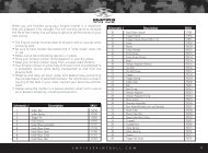
AIR VENT MANIFOLD - Claymore Paintball
AIR VENT MANIFOLD - Claymore Paintball
AIR VENT MANIFOLD - Claymore Paintball

You also want an ePaper? Increase the reach of your titles
YUMPU automatically turns print PDFs into web optimized ePapers that Google loves.
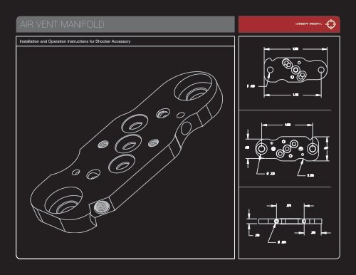
<strong>AIR</strong> <strong>VENT</strong> <strong>MANIFOLD</strong><br />
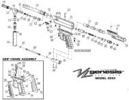
Installation and Operation Instructions for Shocker Accessory
GETTING STARTED<br />
Installing the Air Vent Manifold is of the same<br />
difficulty level as replacing the Shocker SFT’s<br />
solenoid valve. Please read through the entire<br />
set of instructions before beginning.<br />
If you are unsure about your ability to install the Air Vent Manifold yourself, contact<br />
your nearest Smart Parts authorized dealer for professional installation and tuning.<br />
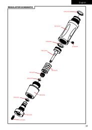
FIG. 01<br />
RECEIVER SIDE VIEW<br />
While the Air Vent Manifold looks much like the stock manifold plate, you can see the<br />
differences on close inspection. The Air Vent Manifold features a pair of very small<br />
setscrews. These two screws can be used to partially block airflow through the plate,<br />
restricting the force applied to move the bolt forward or back.<br />
Forward Flow<br />
Adjust Screw<br />
Rear Flow<br />
Adjust Screw<br />
As you look at the plate, one end is more rounded than the other, this is the front<br />
end. The adjustment screw closest to the front controls the forward, or closing rate<br />
of the bolt, while the screw towards the back controls the rearward, or opening force<br />
of the bolt. [ FIG. 01, FIG 02 ]<br />
Remove the hopper and any paintballs from the Shocker SFT before beginning.<br />
Please follow the guidelines in the Shocker maintenance manual for depressurizing<br />
your marker before disassembling your Shocker. The Shocker SFT must be degassed<br />
and unloaded before you begin. As with any other tech work, disassemble<br />
the Shocker on a clean, flat surface.<br />
FIG. 02<br />
Front<br />
Front<br />
SOLENOID SIDE VIEW<br />
Rear Flow<br />
Adjust Screw<br />
Forward Flow<br />
Adjust Screw<br />
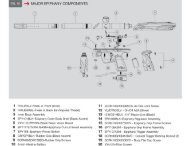
REQUIRED ITEMS FOR INSTALLATION<br />
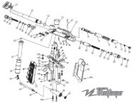
FIG. 03<br />
AVM PLACEMENT<br />
1/16” Allen Wrench · .035” Allen Wrench · SFT Air Vent Manifold [included] · (2) Exhaust Screws, (6) O-Rings<br />
800.922.2147 www.smartparts.com<br />
01
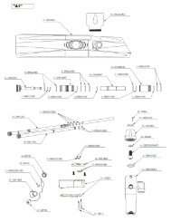
INSTALLATION INSTRUCTIONS<br />
[ PLEASE READ CAREFULLY ]<br />
01 02 03 04<br />
05<br />
06<br />
Remove the grip frame<br />
from the Shocker<br />
body. (Refer to the<br />
disassembly section in<br />
your Shocker owner’s<br />
manual–an additional<br />
hex wrench will be<br />
required.)<br />
Take a good look at<br />
the solenoid valve, and<br />
the manifold plate on<br />
which it is mounted.<br />
The Air Vent Manifold<br />
will be installed in the<br />
same position as the<br />
original manifold plate.<br />
If your Shocker SFT is<br />
equipped with a Vision<br />
Eye, carefully unplug<br />
the Vision flex strip<br />
from the upper circuit<br />
board (the circuit board<br />
mounted on the solenoid<br />
valve.)<br />
Unscrew both solenoid<br />
mounting screws using<br />
a 1/16” Allen Wrench,<br />
and gently pull the solenoid<br />
valve away from<br />
the body.<br />
Note the positions of<br />
the three round o-rings<br />
in the stock manifold<br />
plate. Insert the new<br />
o-rings in their corresponding<br />
positions on<br />
the Air Vent Manifold.<br />
Using the 1/16” Allen<br />
Wrench, remove both<br />
screws that are holding<br />
the old manifold plate<br />
to the Shocker body.<br />
07<br />
08<br />
09 10 11<br />
Note the positions of<br />
the one round and the<br />
two oblong o-rings<br />
in the stock manifold<br />
plate. Insert the new<br />
o-rings in their corresponding<br />
positions on<br />
the Air Vent Manifold.<br />
Save the old o-rings as<br />
spares.<br />
Install the new manifold<br />
plate. The oval shaped o-<br />
ring grooves will face the<br />
Shocker body. Make sure<br />
that the rounded side of<br />
the plate points towards<br />
the barrel end of the<br />
marker. Use firm pressure,<br />
but do not over-tighten<br />
the manifold plate screws.<br />
Replace solenoid and screws using the 1/16” Allen<br />
wrench. Use only a gentle tightness on these screws.<br />
DO NOT OVERTIGHTEN THE SCREWS OR YOU<br />
WILL STRIP THE <strong>MANIFOLD</strong> PLATE.<br />
Reattach the Vision flex<br />
strip with the metal contacts<br />
facing away from<br />
the Shocker SFT body.<br />
Reassemble your<br />
Shocker.<br />
Be careful not to<br />
overstress the solenoid<br />
mounting screws when<br />
aligning the body and<br />
grip frame, or to pinch<br />
the wiring harness<br />
inside the grip frame.<br />
800.922.2147 www.smartparts.com<br />
02
ADJUSTMENT THEORY<br />
The adjusters work by<br />
restricting gas flow.<br />
When you are making adjustments, screwing the forward screw in clockwise will soften<br />
the force used to close the bolt, allowing the Shocker to be more gentle on paint. If you are<br />
experiencing paint breakage in the breech or back of the barrel or simply want to reduce<br />
recoil, turn this adjuster screw in further for softer closing force. Screwing the rear screw in<br />
clockwise will soften the force applied to open the bolt after each shot.<br />
Significant reduction of the forward air flow may require a corresponding increase in the<br />
Shocker’s Dwell setting (see Shocker manual) to maintain proper velocity. Most players will<br />
want to adjust both directions about the same amount, so the recoil has an even feel–just<br />
as strong forward as back–however, the Air Vent Manifold gives you the ability to tune to<br />
what you like best. As you adjust, remember that softening the pressure is slowing bolt<br />
movement, which will ultimately reduce your maximum rate of fire–so only restrict the gas<br />
flow as much as is needed to achieve the feel you want.<br />
Thread locking compound is applied to the adjustment screws at the factory. If, after multiple<br />
adjustments the screws turn freely, you may wish to relock your final setting with a tiny<br />
drop of blue Locktite 242 or equivelant thread locking compound applied to the edge of<br />
the screw.<br />
FIG. 04<br />
FIG. 05<br />
Turn Clockwise to Decrease Flow<br />
Turn Counterclockwise to Increase Flow.<br />
800.922.2147 www.smartparts.com<br />
03
ADJUSTMENT METHODS<br />
Changing the setting of either adjustment<br />
screw does not require complete disassembly<br />
of the Shocker SFT. Follow these steps to<br />
make an adjustment.<br />
With both adjustment screws backed out all the way, the Shocker SFT will operate<br />
as with the stock plate. Turning the screws in (clockwise) will restrict gas flow.<br />
01 02 03 04 05<br />
06<br />
Remove the hopper and<br />
paint, and de-gas the<br />
marker as you did during<br />
installation.<br />
Loosen the grip frame<br />
screws enough to separate<br />
the Shocker SFT<br />
body and grip frame only<br />
far enough to expose<br />
the Air Vent Manifold<br />
(approximately three full<br />
turns)<br />
Be very careful to support<br />
both the body and<br />
grip frame so that they<br />
do not flex and strain the<br />
solenoid mount screws.<br />
Using the 0.035 inch Allen<br />
Wrench, adjust one or<br />
both of the Air Vent Manifold<br />
adjustment screws.<br />
Forward bolt movement<br />
is adjusted from the right<br />
side of the Shocker SFT<br />
[ FIG. 06 ] , rear bolt<br />
movement is adjusted<br />
from the left side of the<br />
Shocker [ FIG. 07 ]<br />
Close the grip frame<br />
and body back together,<br />
and tighten the<br />
grip frame screws.<br />
Take care not to pinch<br />
the wiring harness<br />
inside the grip frame.<br />
If necessary, remove<br />
the Shocker SFT’s<br />
grips and guide the<br />
wiring harness from<br />
below.<br />
Utilizing proper paintball<br />
safety procedures<br />
(goggles designed for<br />
paintball, a safe area,<br />
etc.) test fire the Shocker<br />
SFT, and decide if<br />
you should make further<br />
adjustments.<br />
Repeat from step 1 until<br />
you are pleased with your<br />
newly custom tuned<br />
Shocker SFT. When you<br />
have achieved your final<br />
adjustments, you may<br />
wish to use the tip of the<br />
0.035 inch Allen Wrench<br />
to apply a tiny amount of<br />
temporary thread locking<br />
compound (Blue Loctite<br />
242 or equivalent) to<br />
the edge of the adjuster<br />
screws if the factory applied<br />
thread locker has<br />
worn away.<br />
FIG. 06 FORWARD FLOW ADJUSTMENT<br />
FIG. 07<br />
REAR FLOW ADJUSTMENT<br />
800.922.2147 www.smartparts.com<br />
04